1
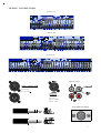
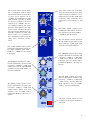
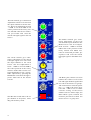
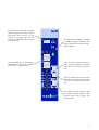
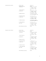
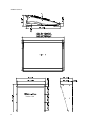
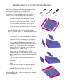
OPERATORS M A N U A L
Klark Teknik Group,
Klark Teknik Building,
Walter Nash Road,
Kidderm inster.
Worcestershire.
DY11 7HJ.
England.
Tel:+44 1562 741515
Fax:+44 1562 745371
Email:[email protected]
W ebsite: m idasconsoles.com
(359 941)
IMPORTANT SAFETY INSTRUCTIONS
The lightning flash with arrowhead symbol, within an equilateral
triangle is intended to alert the user to the presence of
uninsulated “dangerous voltage” within the product’s enclosure
that may be of sufficient magnitude to constitute a risk of electric
shock to persons.
The exclamation point within an equilateral triangle is intended
to alert the user to the presence of important operating and
maintance (servicing) instructions in the literature accompanying the appliance.
1.
2.
3.
4.
5.
Read these instructions.
Keep these instructions.
Heed all warnings.
Follow all instructions.
Do not use this apparatus near water. Do not expose this apparatus to dripping or splashing and ensure that no objects
filled with liquids, such as vases, ase placed on this apparatus.
6. Clean only with a dry cloth.
7. Do not block any of the ventilation openings. Install in accordance with the manufactures instructions.
8. Do not install near any heat sources such as radiators, heat registers, stoves, or other apparatus that produce heat.
9. Only use attachments/accessories specified by the manufacturer.
10. Refer all servicing to qualified service personnel. Servicing is required when the apparatus (including amplifiers) has
been damaged in any way, such as power-supply cord or plug is damaged, liquid has been spilled or objects have
fallen into the apparatus, the apparatus has been exposed to rain or moisture, does not o perate normally, or has been
dropped.
11. To completely disconnect mains power from this apparatus, the power supply cord must be unplugged.
For US and CANADA only:
Do not defeat the safety purpose of the grounding-type plug. A grounding type plug has two bla des and a third
grounding prong. The wide blade or the third prong are provided for your safety. When the provided plug does not
fit into your outlet, consult an electrican for replacement of the absolete outlet.
I M P O R T A N T S E R V ICE INSTRUCTIONS
CAUTION: These servicing instructions are for use by qualified personnel only. To reduce the risk of
electric shock, do not perform any servicing other than that contained in the Operating
Instructions unless you are qualified to do so. Refer all servicing to qualified service personnel.
1. Security regulations as stated in the EN 60065 (VDE 0860) and the CSA E65 - 94 have to be obeyed when
servicing the appliance.
2. Use of a mains separator transformer is mandatory during maintenance while the appliance is opened, needs to be
operated and is connected to the mains
3. Switch off the power before retrofitting any extensions, changing the mains voltage or the output voltage.
4. The minimum distance between parts carrying mains voltage and any accessible metal piece (metal enclosure),
respectively between the mains poles has to be 3 mm and needs to be minded at all times.
The minimum distance between parts carrying mains voltage and any switches or breakers that are not connected
to the mains (secondary parts) has to be 6 mm and needs to be minded at all times.
5. Replacing special components that are marked in the circuit diagram using the security symbol (Note) is only
permissible when using original parts.
6. Altering the circuitry without prior consent or advice is not legitimate.
7. Any work security regulations that are applicable at the location where the appliance is being serviced have to be
strictly obeyed. This applies also to any regulations about the work place itself.
8. All instructions concerning the handling of M O S - circuits have to be observed.
Note:
2
SAFETY COMPONENT (HAS TO BE REPLACED WITH ORIGINAL PART ONLY)
VENICE CONNECTORS
VENICE 160
VENICE 240
VENICE 320
Tape IN / OUT
Input / Output XLR
Pin 1: Ground
Pin 2: Hot
Pin 3: Cold
Lamp out
Pin 1: Chassis
Pin 2: n.c.
Pin 3: Ground
Pin 4: +12V
External Power Supply
3
ATTENTION!
The following special limitations apply to the console and must be observed in order to maintain safety and
electromagnetic compatibility performance:
POWER CONNECTION
The console should only be operated with the power supply connected to ground via its mains supply connector.
AUDIO CONNECTIONS
The console should only be operated with high quality screened twisted pair audio cables. A ll connector shells
should be of metal construction so that they provide a screen when they are plugged into the console. All JACK
connector shells should be connected to the cable screen. All XLR connectors should have pin 1 connected to the
cable screen.
ELECTRIC FIELDS
If the console is operated in an electromagnetic field that is amplitude modulated by an audio frequency signal,
the signal to noise ratio may be degraded. Degradation of up to 60dB may be experienced under extreme conditions
(3V/m, 90% m odulation).
INSTALLATION
There are a number of points to consider when installing a mixing console. Many of these points will have been
addressed before the console is even unpacked but it is worth repeating them.
POSITION
The console should be located in a convenient space commensurate with the use to which the console is being put.
Ideally a cool area is preferred not in close proxim ity to power distribution equipment or other potential sources
of interference. Provision should be made for some flat surface surrounding the console to prevent people using it
as a table top.
INTERNAL POWER SUPPLY
T he console is equipped with an internal power supply. It must be set for the appropriate line voltage and pluged
in to the mains outlet using the supplied cable.
MAINS VOLTAGE SETTING
The console is shipped with a specified mains voltage setting
(see rear panel marking). If the mains voltage is ever changed by
the mains voltage selector at the bottom of the console, the mains
fuse has to be changed as well to the rating matching the selected
voltage on the label.
ADDITIONAL EXTERNAL POWER SUPPLY FOR VENICE 240/320
The power supply should be located as far from the console as the connecting cable will allow. It should be set for
the appropriate line voltage and plugged into the mains outlet using the supplied cable. The external power-supply
overrides the internal supply after power on. The internal supply acts in this case as spare supply.
THE CONSOLE AND THE EXTERNAL POWER SUPPLY SHOULD NEVER BE OPERATED
WITH THE MAINS EARTH DISCONNECTED
Please note that the power supply contains LETHALVOLTAGES and that its rails can produce extremely
large currents which could burn out equipment and wiring if shorted. All testing and servicin g should ONLY
be carried out by qualified engineers.
4
CONTENTS
Mono Input Channel
Page 6
Stereo Input Channel
Page 10
Groups
Page 15
Effects
Page 16
Monitor
Page 17
AUXes
Page 18
Master A/B Tape In
Page 19
Talkback / Phones & Speak
Page 20
Display / Lamp / Phones
Page 21
Block Diagram s
Page 62
Specifications
Page 65
Dimensions
Page 68
Rack Mounting
Page 69
5
M IDAS VENICE
M O N O INPUT
CHANNEL
6
The Venice Mono Channel is
equipped with an XLR input,
which can be used for M ic or
Line level signals up to
+22dBu. An additional ¼ inch
jack socket, provides an input
for line level signals, which require protection against accidental 48 volt connection. The
Line input gives 20dB of permanent attenuation to the input
signal which will allow the connection of extreme high linelevel signals up to +42dBu.
The HI PASS switch connects
the the 80Hz hi-pass-filter in the
input channel signal path before
the insert point and equaliser.
The HI MID control gives continuous adjustment of boost and
cut from + 15dB to - 15dB with
a 0dB centre detent.
The LO MID control gives continuous adjustment of boost and
cut from + 15dB to - 15dB with
a 0dB centre detent.
The +48V led monitors if phantom power is assigned. The
+48V switch for each channel is
placed on the rear-panel of the
console. It connects +48V phantom power to the XLR input connector. This is suitable for a
condenser microphone or DI
box.
The GAIN control gives continuous adjustment of the input
amplifier gain from 0dB to
+60dB for the M ic input and
- 20dB to + 40dB for the Line
input.
The TREBLE control gives continuous adjustment of boost and
cut from + 15dB to - 15dB with a
0dB centre detent. The treble
equaliser acts on 12kHz with a
traditional M IDAS shelving response.
The HI M ID FREQ control gives
continuous adjustment of the frequency range that the hi mid
equaliser acts on from 400Hz to
8kHz with a 1 octave bandwith.
The LO MID FREQ control gives continuous adjustment of the
frequency range that the lo m id
equaliser acts on from 100Hz to
2kHz with a 1 octave bandwith.
The BASS control gives continuous adjustment of boost and
cut from + 15dB to - 15dB with
a 0dB centre detent. The bass
equaliser acts on 80Hz with a traditional M I D A S s h e l v i n g r esponse.
The EQ switch connects the
equaliser in the input channel signal path.
7
The FX controls give continuous
adjustment of the post fader level
sent from the input channel to the
FX busses. The level adjustment
is from + 10dB to off with 0dB
at the centre position of the rotary control.
The MON controls give continuous adjustment of the pre- fader and pre- equaliser signal sent
from the input channel to the
MON busses. The level adjustment is from + 10dB to off with
0dB at the centre position of the
rotary control.
The AUX controls give continuous adjustment of the level
sent from the input channel to the
AUX busses. The level adjustment is from + 10dB to off with
0dB at the centre position of the
rotary control.
AUX1 and 2 can be configured
globally for pre- or post-fader
operation by pressing the
PRE/POST switch on the appropriate A U X -rail in the master
section.
The PAN controls the channel
placement within the master stereo- or group mix and has a constant power law. i.e. - 3dB at the
centre position and 0dB or off at
either extreme setting.
The MUTE switch mutes the input channel at all points after the
insert send, including all auxiliary sends.
8
The SOLO switch sends the input channel signal to the PFL /
mono-and AFL / stereo busses.
If the sw itch is engaged, the
mon1/2 meters are automatically
used for solo metering.
The SIGNAL (-16dBu) / PEAK
(+16dBu) display monitors the
peak signal level of the pre fader
input channel.
The FADER gives continuous
adjustment of the input channel
level from + 10dB to off.
The 1-2 switch connects the post
fader channel signal to the group
1-2 busses via the pan control.
The 3-4 switch connects the post
fader channel signal to the group
3-4 busses via the pan control.
The MAS switch connects the
post fader channel signal to the
master stereo bus via the pan control.
9
M IDAS VENICE
STEREO INPUT
CHANNEL
10
The Venice stereo input channel is equipped with an XLR
input which can be used for M ic
or Line level signals up to
+22dBu. Two additional ¼ inch
jack sockets, provide an input
for Stereo- or Mono Line level
signals up to +28dBu. The stereo channel features the same
hi-value m icrophone pre-amp
as the mono channel. Because
the stereo input channel uses independet circuits for M ic and
Stereo Line , it is possible to
have all inputs connected at the
s a m e t i m e , w i t h o u t i n t e r f erence.
The LINE TRIM control gives
continuous adjustment of the stereo input amplifier gain from 20dB to + 20dB for the Stereo
Line input.
The HI MID control gives continuous adjustment of boost and
cut from + 15dB to - 15dB with
a 0dB centre detent. The HI M ID
equaliser acts on 3kHz with a 1.4
octaves bandwith.
The BASS control gives continuous adjustment of boost and
cut from + 15dB to - 15dB with
a 0dB centre detent. The bass
equaliser acts on 80Hz with a
traditional M IDAS shelving response.
The +48V switch for each channel is positioned at the rear panel
of the console. It connects +48 V
phantom power to the XLR input
connector. This is suitable for a
condenser m icrophone or DI
box.
The M IC GAIN control gives
continuous adjustment of the input amplifier gain from 0dB to
+ 60dB for the M ic input.
The HI PASS switch connects
the the 80Hz hi-pass-filter in the
input channel signal path right
after the m ic input amplifier.
The TREBLE control gives continuous adjustment of boost and
cut from + 15dB to - 15dB with
a 0dB centre detent. The treble
equaliser acts on 12kHz with a
traditional M IDAS shelving response.
The LO MID control gives continuous adjustment of boost and
cut from + 15dB to - 15dB with
a 0dB centre detent. The LO
M ID equaliser acts on 300Hz
with a 1.4 octaves bandwith.
The EQ switch connects the
equaliser in the input channel signal path.
11
The FX controls give continuous
adjustment of the level sent from
the input channel to the FX busses. The level adjustment is from
+ 10dB to off with 0dB at the
centre position of the rotary control. The FX controls are connected post-fader and send the
mixed left/right signal to the FX
busses.
The AUX controls give continuous adjustment of the mixed
left/right signal level sent from
the input channel to the AUX
busses. The level adjustment is
from + 10dB to off with 0dB at
the centre position of the rotary
control. AUX1 and 2 can be configured globally for pre- or postfader operation by pressing the
PRE/POST switch on the appropriate A U X -rail in the master
section.
The MUTE switch mutes the input channel at all points, including all auxiliary sends.
12
The M O N controls give continuous adjustment of the level
sent from the input channel to the
MON busses. The level adjustment is from + 10dB to off with
0dB at the centre position of the
rotary control. The M O N controls are connected pre fader, pre
equaliser and send the mixed
left/right signal to the MON busses.
The BAL (pan) control is used to
balance the relative levels of the
left and right channel signals that
are sent to the masters or groups.
The control has a constant power
law, i.e. -3dB at the centre position and + 0dB or off at either
extreme setting. If the Stereo
channel used as mono input, the
B A L A N C E (pan) controls the
channel placement within the
master stereo- or group m ix.
The SOLO switch sends the input
channel signal to the PFL/ mono
and AFL/ stereo busses. If the
switch is engaged, the mon1/2
meters are automatically used for
solo metering.
The FADER gives continuous
adjustment of the input channel
level from + 10dB to off.
The SIGNAL (-16dBu) / PEAK
(+16dBu) display monitors the
peak signal level of the pre fader
input channel.
The 1-2 switch connects the post
fader channel signal to the group
1-2 busses via the bal (pan) control.
The 3-4 switch connects the post
fader channel signal to the group
3-4 busses via the bal (pan) control.
The MAS switch connects the
post fader channel signal to the
master stereo bus via the bal
(pan) control.
13
M IDAS VENICE
M A STER SECTION
14
The PAN controls the group placement within the master stereomix and has a constant power
law i. e. -3dB at the centre position and 0dB or off at either extreme setting.
The SOLO switch sends the
group signal to the PFL / mono
and AFL / stereo busses. If the
switch is engaged the mon 1/2
meters are automatically used
for solo metering
The MAS switch connects the
post fader group signals to the
stereo master bus via the pan
control.
The SIGNAL (-16dBu) PEAK
(+16dBu) display monitors the
signal level of the group bus.
The GROUP faders give continuous adjstment of the sub group
output levels from +10dB to off.
15
The FX SEND control gives continuous adjustm e n t of the FX
send output level from +10dB to
off with 0dB at the centre position of the rotary control.
The M O N controls give continuous adjustment of the pre- fader signal sent from the FXreturn channel to the MON busses. The level adjustment is from
+ 10dB to off with 0dB at the
centre position of the rotary control.
The 1-2 switch connects the post
fader FX- return left signal to the
group 1 bus and right signal to
the group 2 bus.
The 3-4 switch connects the post
fader FX- return left signal to the
group 3 bus and right signal to
the group 4 bus.
The M A S switch connects the
post fader FX- return stereo signal to the stereo master bus.
The MUTE switch mutes the FXreturn at all pointes.
The SOLO switch sends the FXreturn signal to the PFL / mono
and AFL / stereo busses. If the
switch is engaged the mon 1/2
meters are automatically used
for solo metering
The FADER gives continous adjustment of the FX- return level
from +10dB to off.
16
T h e M U T E s w itch mutes the
monitor send output signal.
The SOLO switch routes the m onitor send signal to the PFL/
mono and AFL/ stereo busses. If
the switch is engaged, the mon
1 / 2 m e t e r s a r e a u t o matically
used for solo metering.
The M O N S E N D fader gives
continuous adjustment of the
monitor send signal from +10dB
to off.
17
The global AUX PRE/POST
switch configures the aux bus
either in pre- fader (mon) or
post-fader (fx) operation. The
LEDs next to the switch provide
indication of status.
The MUTE switch mutes the aux
send output signal. It does not affect the aux return.
The AUX SEND control gives continuous adjustment of the aux send output level from +10dB to off with 0dB
at the centre position of the rotary
control.
The SOLO switch routes the aux send
signal to the PFL/ mono and AFL/
stereo busses. Whenever a solo switch
is engaged the man 1/2 display is auto matically used for solo metering.
18
The AUX RETURN control gives
continuous adjustment of the stereo
aux return level from +10dB to off
with 0dB at the centre position of the
rotary control. The aux return signals
are directly routed to the L/R master
busses.
The M O N controls give continuous adjustment of the level sent from the aux return to
the MON busses. The level adjustment is
from +10dB to off with 0dB at the centre
position of the rotary control.
The TAPE inputs provide a feed
from an unbalanced phono source to the stereo master busses or
to phones and speakers outputs.
The TAPE IN level control provides nom inal adjustment from
+20dB to off with 0dB at the centre position of the rotary control.
The MASTERS B rotary control
gives continuous adjustment of
the masters B (stereo/mono) output level from +10dB to off with
0dB at the centre position of the
rotary control.
By the STEREO/M O N O switch
the Master B outputs can be configured in two modes. In STEREO mode the master b outputs
are fed with the stereo left and
right m ix signals. In Mono mode
they are fed with the sum m ed left
and right m ix signal.
The MUTE switch mutes all signals sent to master and master b
outputs. Only the Tape In signal
to masters is not affected by the
MUTE switch.
The MAS switch connects the
TAPE IN signal to the master
L/R busses right after the master
mute switch. This allowes i. e.
background music during a
show, even when the master
m u te sw itch is engaged. The
MAS switch should be off during
recording via TAPE OUT.
The PRE/POST switch changes
the signals sent to the masters b
outputs from pre master fader to
post master fader.
The BAL control is used to balanced the relative levels of the
left and right master signals that
are sent to the masters outputs.
The control has a constant power
law, i. e. 0dB at the centre position and +3dB or off at either extreme setting .
The stereo Fader gives continous
adjustment of the left and right
m ix levels from +10dB to off.
19
The talkback LEVEL control gives continuous adjustment of the
talkback signal from +50dB to
off. The talkback input accepts a
maximum input level of +8dBu.
The non-latching M O N switch
connects the talkback mic to
mon1 and mon2 busses.
The non-latching AUX switch
connects the talkback m ic to
aux1 and aux2 pre-busses.
The PHONES level control gives continuous adjustment of the
level from +10dB to off at the
phones output a&b.
The SPEAKERS level control
gives continuous adjustment of
the signal at the speakers left and
right output from +10dB to off
with 0dB at the centre position of
the rotary control.
The SOLO control adjusts the
incom ing solo level before sending it to the headphones and
speaker outputs. The control
range is -20dB to +20dB with
0dB in centre position.
20
The non-latching GRP switch
connects the talkback m ic to all
group busses.
The non-latching M A S switch
connects the talkback m ic to left
and right master busses.
The SOURCE switch controls
whether the tape in or master signal is present at the headphones
and control room speaker outputs, if no solo button is engaged.
If a solo button is engaged the
PFL / AFL switch controls whether the mono pre fader listen or
the stereo after fader listen signal
is present at the headphones and
control room speaker outputs.
The input for a TALKBACK Microphone is provided via a 3pinfemale XLR connector. The +48V
Phantom power is permanently
connected which is suitable for
condenser m icrophones.
A convenient connection for two
12V desk lamps is provided via the
4pin-female XLR connectors. The
power rating 5W is the maximum
rating per output and may not be
exceeded.
Whenever a solo button is engaged the SOLO led turns on
and the mon 1/2 metering is
autom a tically used as solo
meter.
In pfl-mode the mon1 meter
displays the signal level in
dBu of the selected solo source at the pre- fader position.
In afl-mode the mon1 (afl-l)
and mon2 (afl-r) meters are
active and display the signal
levels in dBu in the stereo
image at the after- fader position.
The 1/4 inch jack sockets
provide stereo outputs for
two PHONES. Both outputs
are controlled via the phones
rotary control.
T h e M O N m eters display the
post fader peak signal levels of
the monitor outputs. Whenever a
solo button is engaged the meter
displays the peak signal levels of
the selected pfl or afl solo source.
The MASTER meters monitor
the peak signal levels of the m aster outputs left and right (post
fader).
21
BLOCK DIAGRAMS
Mono Channel
Stereo Channel
22
FX-send, FX-return
Aux, Groups and Talkback
23
Master, Monitor, Tape and Solo
24
MIDAS VENICE SERIES PERFORMANCE SPECIFICATIONS
Features and Specifications
Inputs (total)
Mono-Inputs (M ic/Line) with Inserts
Stereo-Line/Mono-Mic-Input Channels
Stereo-Effect-Returns (Line)
Stereo-Tape-Return (Line)
Venice 160
30
8
4/4
4
Busses
Subgroups
Aux Pre-Fader (Monitor)
Aux Post-Fader (Effects)
Aux switchable Pre/Post-Fader
Master L/R
Mono-PFL
Stereo-AFL
Venice 240
Venice 320
38
16
4/4
4
1 left/right
46
24
4/4
4
15
4
2
2
2
2
1
2
Outputs
Subgroups (with Inserts)
Aux Pre-Fader (Monitor)
Aux Post-Fader (Effects)
Aux switchable Pre/Post-Fader
Master (with Inserts)
Master B Out
(switchable Mono/Stereo, pre-post Fader)
Tape Send (Recording)
Direct Outputs (1/4 inch Jack)
Stereo-Headphones
Stereo-Speakers
4
2
2
2
impedance balanced 1/4 inch jacks
XLR (balanced)
impedance balanced 1/4 inch jacks
XLR (balanced)
2 XLR (balanced)
2 XLR (balanced)
1 Stereo (Phono)
16
24
2 Stereo-1/4 inch jack
2 impedance balanced 1/4 inch jacks
8
Size (m m /inch)
W idth
Depth
Heights
490 / 19.3“
568 / 22.4“
194 / 7.6“
698 / 27.5“
568 / 22.4“
194 / 7.6“
906 / 35.7“
568 / 22.4“
194 / 7.6“
Weight (kg/lbs)
16,4 / 36.2
21,1/ 46.5
25,8 / 56.9
Power Consumption
75W
95W
120W
Mains Voltage
110V/120V/220V/230V/240V, 50-60Hz
Additional Features
Connector for desk lamps
19“-rack-mounting- kit,
rotatable connector panel
External Power Supply (EPS 1200, not included)
yes
yes
-
Accesories
2 x 12V/5W (4-Pin XLR)
yes
yes
Dust Cover (included)
12 V Desk Lamp (not included)
Input Transformer (not included)
25
Venice Technical Specifications
Input Impedance
M ic
Line
2k Balanced
20k Balanced
Input Gain
M ic
Continuously variable from
0dB to + 60dB
Line Mono Channel
Continuously variable from
- 20dB to + 40dB
Line Stereo Channel
Continuously variable from
- 20dB to + 20dB
Line Level Inputs
0dB
Maximum Input Level
M ic
Line Level Inputs
Line Mono Channel
Line Stereo Channel
+
+
+
+
CMR at 100Hz
M ic (gain + 40dB)
Typ. 75dB
CMR at 1kHz
M ic (gain + 40dB)
Line
> 85dB
> 45dB
Frequency Response
(20 to 20kHz)
M ic to M ix
(gain + 60dB)
+ 0dB to - 1dB
Noise (20 to 20kHz)
M ic EIN ref. 150ohms
(gain + 60dB)
- 129dBu
Summing Noise
(16 channels routed
with faders down)
- 90dBu
Line to M ix Noise
(16 channels routed
at 0dB, pan centre)
- 86dBu
M ic to Insert (+ 30dB
gain, + 20dBu output)
Typ 0.0007%
M ic to M ix (+30dB
gain, + 20dBu output)
< 0.009%
Crosstalk at 1kHz
Channel to Channel
M ix to M ix
Channel to M ix
Fader Attenuation
Switch Rejection
<
<
<
>
>
Output Impedance
All Line Outputs
Headphones
75 Ohms Balanced Source
To drive 32ohms
Maximum Output Level
Master Outputs on XLR
All other Outputs on XLR
All Outputs on 1/4 inch jacks
Headphones
+
+
+
+
Nominal Signal Level
M ic
Line
- 60dBu to 0 dBu
0dBu
22dBu
22dBu
42dBu
28dBu
System Noise (20 to 20kHz)
Distortion at 1kHz
26
- 80dB
- 80dB
- 80dB
100dB
100dB
25dBu
22dBu
22dBu
22dBu/600ohms
Equaliser Mono Channel
Equaliser Stereo Channel
Hi Pass Slope
Hi Pass Frequency
Treble Gain
12dB / Oct
80Hz
Continuously variable
+ 15 dB to - 15 dB
Centre detent = 0dB
Treble Frequency
Hi Mid Gain
12k
Continuously variable
+ 15 dB to - 15 dB
Centre detent = 0dB
Hi Mid Frequency
Continuously variable
Centre from 400Hz to 8k
Hi Mid Bandwidth
1 Oct. (Q = 1.4)
Lo Mid Gain
Continuously variable
+ 15 dB to - 15 dB
Centre detent = 0dB
Lo Mid Frequency
Continuously variable
Centre from 100Hz to 2k
Lo Mid Bandwith
1 Oct. (Q = 1.4)
Bass Gain
Continuously variable
+ 15 dB to - 15 dB
Centre detent = 0dB
Bass Shelving Frequency
80Hz
Hi Pass Slope
12dB / Oct
Hi Pass Frequency
80Hz
Treble Gain
Continuously variable
+ 15 dB to - 15 dB
Centre detent = 0dB
Treble Frequency
12k
Hi Mid Gain
Continuously variable
+ 15 dB to - 15 dB
Centre detent = 0dB
Hi Mid Frequency
3k
Hi Mid Bandwidth
1.4 Oct. (Q = 1)
Lo Mid Gain
Continuously variable
+ 15 dB to - 15 dB
Centre detent = 0dB
Lo Mid Frequency
300Hz
Lo Mid Bandwidth
1.4 Oct. (Q = 1)
Bass Gain
Continuously variable
+ 15 dB to - 15 dB
Centre detent = 0dB
Bass Shelving Frequency
80Hz
27
DIMENSIONS
Venice 160
28
Modification for Venice 160 Rack Mounting
The Venice 160 comes with additonal rack mounting
brackets. For modification you need a Torx
screwdriver type T20 (fig.1) and Phillips screwdrivers
type Ph1 (fig. 2) and type Ph2 (fig.3). To modify the
Venice 160 for rack mounting follow these steps:
fig. 1
1. Disconnect the unit from mains by all means.
Remove all cables (mains, audio, lamp, etc.).
2. Loosen the 16 screws shown in fig. 4 with the
Torx screwdriver and remove the two plastic
side covers and the armrest. Keep the side
covers, the armrest and the screws for later use.
Attention: If you wish to rotate the connection
panel in addition to the rack bracket mounting
(fig. 6), perform steps 3 – 8. If not, proceed directly
to step 9.
3. Turn the unit upside down and place it carefully
on a smooth support.
4. Loosen the 8 screws fastening the cover sheet
and the connection panel on the sides of the unit
(fig. 5) with the Phillips screwdriver type Ph1.
5. Then dismount the connection panel with the 6
screws (fig. 5). Be careful not to unplug the
cable connectors by mistake. Then remove the
cover sheet via 3 further screws.
6. The cover sheet must be mounted with the
angular side up, like shown in fig. 6. The
connection panel is now mounted in such a way
that the mains socket is left upwards on the unit
(fig. 6).
7. The cover sheet and the connection panel are
fastened additionally with 8 screws on the sides
of the unit.
8. Turn the unit and place it with the control panel
upside.
9. Finally the rack brackets are fastened with the
screws contained in the mounting set (fig. 7) by
using the Phillips screwdriver type Ph2.
fig. 4
fig. 5
fig. 6
Warning: Use only screws which were loosened
during modification or such ones, which are contained
in the mounting set.
fig. 7
fig. 2
fig. 3