1
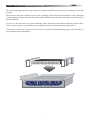
DN500
OPERATORS MANUAL
Klark Teknik Group,
Klark Teknik Building,
Walter Nash Road,
Kidderminster.
Worcestershire.
DY11 7HJ.
England.
Tel:+44 1562 741515
Fax:+44 1562 745371
Email: [email protected]
Website: www.klarkteknik.com
IMPORTANT SAFETY INSTRUCTIONS
CAUTION
RISK OF ELECTRIC SHOCK
DO NOT OPEN
WARNING: TO REDUCE THE RISK OF FIRE OR ELECTRIC SHOCK,
DO NOT EXPOSE THIS APPLIANCE TO RAIN OR MOISTURE
AVIS: RISQUÉ DE CHOC ELETRIQUE. NE PAS OUVRIR
These symbols are internationally accepted symbols that warn of potential hazards with
electrical products.
The lightning flash with arrowhead symbol, within an equilateral
triangle is intended to alert the user to the presence of uninsulated
“dangerous voltage” within the product's enclosure that may be of
sufficient magnitude to constitute a risk of electric shock to persons.
The exclamation point within an equilateral triangle is intended to alert
the user to the presence of important operating and maintenance
(servicing) instructions in the literature accompanying the appliance.
1. Read these instructions.
2. Keep these instructions.
3. Heed all warnings.
4. Follow all instructions.
5. Do not use this apparatus near water.
6. Clean only with a dry cloth.
7. Do not block any of the ventilation openings. Install in accordance with the manufacturers
instructions.
8. Do not install near any heat sources such as radiators, heat registers, stoves, or other apparatus that
produce heat.
9. Do not defeat the safety purpose of the polarized or grounding-type plug. A polarized plug has two
blades with one wider than the other. A grounding type plug has two blades and a third grounding
prong. The wide blade or third prong are provided for your safety. When the provided plug does not fit into
your outlet, consult an electrician for replacement of the obsolete outlet.
10. Protect the power cord from being walked on or pinched particularly at plugs, convenience
receptacles, and the point where they exit from the apparatus.
11. Unplug this apparatus during lightning storms or when unused for long periods of time.
12. Refer all testing to qualified personnel. Servicing is required when the apparatus is damaged in any way,
such as power-supply cord or plug is damaged, liquid has been spilled or objects have fallen into the
apparatus, the apparatus has been exposed to rain or moisture, does not operate normally, or has been dropped.
Walter Nash Road, Kidderminster, Worcestershire. DY11 7HJ. England
Tel: +44 1562 741515. Fax: +44 1562 745371
Company Registration No: 2414018
abc abc
SIGNAL PROCESSING BY DEFINITION
DESIGNED FOR A PURE PERFORMANCE
DECLARATION OF CONFORMITY
We, Klark Teknik Group (UK) PLC
of,
Klark Teknik Building, Walter Nash Road, Kidderminster, Worcestershire, DY11 7HJ
Declare that a sample of the following product:Product Type Number
DN500 Plus
Product Description
Nominal Voltage (s)
Current
Freq
115V AC
230V AC
200mA
100mA
50/60Hz
Dual Compressor /
Limiter / Expander
to which this declaration refers, is in conformity with the following directives and/or standards:Directive(s)
89/336/EEC Electromagnetic Compatibility Directive
amended by 92/31/EEC & 93/68/EEC 73/23/EEC,
Low Voltage Directive, amended by 93/68/EEC
Generic Standard Using EN55103 Limits and Methods
Class B Conducted Emissions Pavi
Class B Radiated Emissions Pavi
Fast Transient Bursts at 2kV
Static Discharge at 4kV
Electrical Stress Test
Electrical Safety
Signed:............................
Test Standard(s)
EN50081/1
EN55103
EN55103
EN61000-4-4
EN61000-4-2
EN60204
UL6500-99
EN60065:1998
E60065-00
Date: 15th September 2003
Name: Simon Harrison
Authority: Research and Development Director, Klark Teknik Group (UK) PLC
Attention!
Where applicable, the attention of the specifier, purchaser, installer or user is drawn to special limitations of use
which must be observed when these products are taken into service to maintain compliance with the above
directives. Details of these special measures and limitations to use are available on request and are available
in product manuals.
A Subsidiary of Telex communications, Inc.
l abc
Contents
Klark Teknik DN500
After you have unpacked
1
3
Introduction
5
Instrument Familiarisation
Front panel controls
Rear panel controls
7
8
Audio Connections
11
Using the DN500
Compression
Setting the Controls
Expansion
Setting the Controls
Limiting
13
14
15
17
18
19
Compression, Expansion and Limiting together
20
Application notes
Linking to the Console
Using the Side Chain
De-essing
21
22
23
Technical Specification
25
l abc
.
The
Klark Teknik DN500
l abc
Thank you for selecting the Klark Teknik DN500 Plus dual compressor / limiter / expander. The unit continues
the Klark Teknik tradition of providing superb audio performance, technical accuracy and rugged reliability.
Precautions
Do not install this unit in a location subjected to excessive heat, dust or mechanical vibration.
Voltage Selection and Power Connection
Connection is made by means of an IEC standard power socket. The rear panel text indicates the voltage range
required for satisfactory operation of the unit.
Before connecting this unit to the mains supply, ensure the fuse fitted is the correct type and rating is as
indicated on the rear panel, adjacent to the fuse holder.
Safety Warning
This unit is fitted with a standard fused IEC mains inlet: For safety reasons the earth lead should never be
disconnected.
To prevent shock or fire hazard, do not expose the unit to rain or moisture. To avoid electrical shock do not
remove covers. Refer servicing to qualified personnel only.
Attention! Cables
This product should only be used with high quality, screened twisted pair audio cables, terminated with metal
bodied 3-pin XLR connectors. Any other cable type or configuration for the audio signals may result in
degraded performance due to electromagnetic interference.
Electric Fields:
Should this product be used in an electromagnetic field that is amplitude modulated by an audio frequency
signal (20Hz to 20kHz), the signal to noise ratio may be degraded. Degradation of up to 60dB at a frequency
corresponding to the modulation signal may be experienced under extreme conditions (3V/m, 90%
modulation).
1
l abc
2
After You Have Unpacked The Unit
l abc
Save all the packing materials - they will prove valuable should it become necessary to transport or ship this
product.
Please inspect this unit carefully for any signs of damage incurred during transportation. It has undergone
stringent quality control inspection and every possible effort has been made to ensure that it left the factory in
perfect condition.
If, however, the unit shows any signs of damage, please notify the transportation company without delay.
Only you, the consignee, may institute a claim against the carrier for damage during transportation.
If necessary, contact your supplier or as a last resort, your Klark Teknik importing agent, who will fully cooperate under such circumstances.
This
Side Up
KIDDERMINSTER ENGLAND
3
l abc
4
Introduction
l abc
Compression, expansion, limiting and peak clipping are four of the most valuable techniques available to the
sound engineer. Not only can they solve many problems that can arise in day to day work, creative
possibilities exist in abundance.
The Klark Teknik DN500 Plus Dual Compressor/Limiter/Expander integrates all of these processes into a
single, compact, rack mounting unit with two channel operation. Complete dynamic control over gain is the
result, and also control over problems due to noise in the signal chain and the distortion that may be caused by
excessive peak levels.
As a compressor, the DN500 Plus can achieve almost undetectable dynamic range reduction by the use of
sophisticated automatic attack and release circuitry. Or compression can be used as an effect in its own right
with full manual control over Threshold, Ratio, Attack and Release. There is also a fully adjustable 'Knee'
control which provides an infinite range of compression styles from Hard to Soft, 'easy' compression.
As an expander, the DN500 Plus offers variable ratio expansion which can be used to increase subtly the
dynamic range of a signal, or to act as a conventional noise gate, or offer any degree of expansion in between.
To control signal peaks, a Limiter is provided on each channel totally independent of the Compressor, and
with a fully adjustable Threshold control. For situations where absolute control over peaks is necessary, a
Peak clipper can be switched in, the threshold of which tracks the Limiter.
The DN500 Plus has light indicators for every switched audio function, and also has separate gain reduction
light bar graph meters for compression and expansion on each channel. There are also peak limiting light
indicators and output level light bar graph meters for each channel.
Separate side chain inputs are provided for the Compressor and Expander sections. A stereo link function is
available for operation of the Compression and Expansion functions of both channels of the unit from the
controls of channelA.
The DN500 Plus Dual Compressor/Limiter/Expander is built to Klark Teknik's high standards of design and
construction. A well thought out aesthetic presentation is also an aid to realising full dynamic control over
gain in today's complex productions.
5
l abc
6
Instrument Familiarisation: Front Panel Controls
7
6
1
8
2
15
9
3
4
5
10
11
l abc
13
12
14
17
18
16
The DN500 Plus Dual Compressor/Limiter/Expander consists of two identical channels, each with separate
Compressor, Expander and Limiter sections.
Compressor
1.
Threshold determines the level above which gain reduction (compression) will take place, variable
from +20dBu down to -30dBu. The Gain Reduction light bar graph meter indicates in decibels by how
much the signal is compressed at any instant.
2.
Ratio sets the degree of compression applied above the threshold level, variable from 1:1 to 50:1. A
ratio of 1:1 corresponds to zero compression : Signal In = Signal Out. A ratio of 10:1 indicates that
when the input signal, above the threshold, rises in level by 10dB, the output level will rise 1dB.
3.
Knee calibrated from 1 to 40, adjusts the 'hardness' or 'softness' of the compression effect. Ahard knee
means that when the input signal level rises above the threshold, it is immediately compressed at the
full ratio as set. A soft knee means that compression will start below the threshold level at a low ratio
and gradually attain the full ratio selected only at higher levels.
4.
Attack sets the time taken for compression to commence after the threshold is exceeded, from 0.05
milliseconds (50 microseconds) to 20 milliseconds.
5.
Release determines the time taken for the gain to return to normal after the signal drops below the
threshold level, adjustable from 60 milliseconds to 2 seconds.
6.
The Bypass switch selects the whole channel to be in or out of circuit.
7.
Stereo links the two channels of the DN500 Plus together, so that they are both operated from the
controls of Channel A, apart from the Limiter sections which always work individually. In stereo
mode, the unit still monitors the levels of both channels to detect when the signal is above the threshold
level (on Channel B, the Stereo switch is replaced by a 'Stereo Slave' light indicator).
8.
Comp In selects the compression effect to be in or out.
9.
ENV allows the setting of attack and release times to be automatic or manual. On Auto, the attack
time of the input signal and the amount by which it exceeds the threshold level are assessed, and
suitable Compressor attack and release values set to give an almost undetectable
reduction in signal dynamic range. On Manual, the rotary Attack and Release controls come into
operation.
7
l abc
Expander
10.
Threshold determines the level below which gain reduction will take place, variable from 20dBu
down to -40dBu. Gain reduction BELOW a threshold level constitutes dynamic range EXPANSION.
The Gain Reduction light bar graph meter indicates in decibels by how much the signal is expanded at
any instant.
11.
Ratio sets the degree of expansion applied below the threshold level, variable from 1:1 to 25:1. A
ratio of 1:1 corresponds to zero expansion : Signal In = Signal Out. Aratio of 10:1 indicates that when
the input signal, below the threshold, falls in level by 1dB, the output level will fall 10dB.
12.
Release determines the time taken for the gain to return to normal after the signal comes back above
the threshold level, adjustable from 40 milliseconds to 2 seconds.
13.
ATK (Attack) is a switched control offering either automatic signal-monitored setting of Expander
attack time or a fixed value of 2 milliseconds.
14.
Gain is the output level control for the entire channel, Compressor, Expander and Limiter. The output
level light bar graph meter indicates OUTPUT level when the channel is switched in circuit. When
the channel is bypassed, the meter indicates INPUT level.
15.
EXPIn selects the expansion effect to be in or out.
Limiter
16,
Threshold sets the level above which the signal will be limited (compressed at a high 25:1 ratio),
adjustable from 0dBu to 20dBu.
17.
Clipper In selects peak clipping. Clipping totally eliminates transient peaks, effectively acting as a
limiter with an infinity:1 ratio and an instantaneous attack time. The Clipper threshold follows the
Limiter threshold as set.
18.
Power switches mains power on or off.
8
Instrument Familiarisation: Rear Panel Controls
22
26
19
l abc
23
115/220-240V
1
2
1
3
C
2
1
2
1
3
3
2
3
US
NEUTRIK
20
21
24
NEUTRIK
NEUTRIK
NEUTRIK
25
19.
Mains is supplied via an IEC standard 3-pin connector. A compatible power cord is supplied with the
unit.
20.
The mains fuse is located in a fuse holder fitted to the rear panel. Always replace with the correct type
and rating as indicated on the unit.
21.
Voltage selector switch. This unit is switchable between two nominal supply voltages, 110V and
220V, via a slide switch. The switch MUST be set before the supply is connected. Any attempt to run
the unit from a 220V supply with the switch set to 110V is liable to result in severe damage to the unit.
Note: Units for the Japanese market do not have an accessible mains voltage selector switch and are set for 100V
operation only.
22.
Signal Input is made via a female XLR type connector.
23.
Signal Output is available on a male XLR type connector. For wiring details see page 11 of this
manual.
24.
Expander Side Chain Input is made via a ¼ inch typeAstereo jack connector.
25.
Compressor Side Chain Input is made via a ¼ inch typeAstereo jack connector.
26.
Always quote the Serial Number in any correspondence concerning the unit.
9
l abc
10
Audio Connections
l abc
Input
The input circuit is a transformerless, electronically balanced design which achieves a symmetry of better
than- 50dB from 20Hz to 10kHz.
If transformer balancing of the input is required, this must be specified at the time of order. It is not
retrofittable.
Output
The standard output is unbalanced, but balancing transformers are available and may be retrospectively
fitted. Please contact your Klark Teknik representative for more information. The output circuitry is capable
of driving a 600 ohm load at a level of +22dBu.
Input
Balanced
Unbalanced
2
1 Gnd
1
3
2
1
3
2 Hot
1 Gnd
2 Hot
3 Cold
3 Gnd
Output
Balanced
Unbalanced
1
1 Gnd
2
3
2 Hot
3 Gnd
1
2
3
1 Gnd
2 Hot
3 Cold
Pin 2 / Pin 3 Hot Operation
As standard the unit is configured for the pin 2 hot XLR wiring convention. It is possible to re-configure the
unit for pin 3 hot operation please contact your Klark Teknik service representative for details.
11
l abc
Side Chain/EXT Key Inputs
The electronically balanced Side Chain inputs are on stereo ¼ inch typeAjack sockets, configured:
TIP = HOT, RING = COLD, SLEEVE = EARTH.
Inserting a mono jack plug will automatically unbalance the input.
1/4” Stereo Jack
HOT
COLD
In
Thru
Out
GND
The sockets are internally normalled so that signal continuity is maintained when there is no jack plug
inserted. If the unit is wired to a patchbay, then normalling must be carried out at the patchbay.
Balanced Circuits
Transformer or electronically balanced connections have the benefit of Common Mode Rejection which
eliminates externally induced interference, such as mains hum etc. Balancing is especially useful when long
cable runs are used between pieces of equipment.
Transformer balanced circuits have the added advantage of being fully floating, with the earth (ground) or
screen being totally isolated from the signal. In installations where a difference in earth potential is likely to
occur, this isolation prevents earthing problems which can, in some cases, damage the equipment.
12
Using the DN500
l abc
The natural sounds of life have an extremely wide dynamic range, from the result of a falling leaf to the roar of
a jet engine on take off. The human ear has an automatic gain control which enables it to accommodate all of
these sounds from the threshold of hearing to close to the threshold of pain, a dynamic range of approximately
120 decibels.
Even the most modern audio equipment is incapable of handling the full range that the ear can cope with.
Analogue tape without noise reduction can manage almost 70 decibels dynamic range between its noise floor
and the 3% distortion point. 16 bit digital audio equipment can achieve over 90dB. Still almost 30dB less
than the ear's range.
Even if a 120dB dynamic range were possible in audio equipment, would it be desirable and useful? A
listener in a domestic setting enjoying the exhilarating effects of a 96dB Sound Pressure Level will almost
certainly be causing his neighbour a significant amount of annoyance, if not distress! At the other end of the
dynamic scale, a typical ambient noise level of at least 40dB SPL precludes the use of very quiet levels in
recorded or broadcast sound media.
Almost always, it is necessary to compress the dynamic range of natural sounds to fit them into a window
suitable both for the equipment and for comfortable listening.
Although the dynamic range of the programme material must fit into a 30 to 40dB window, there is another
factor in the equation noise. All the sounds that we want to listen to, whether natural or electronically
processed, are accompanied by a certain amount of unwanted background noise tape hiss, or the rustle of
musicians turning the pages of the score in the studio.
Even if, in the final programme, the noise level is below the ambient noise of the listening area, it may still be
heard and is therefore undesirable.
The Compressor/Limiter and the Expander are valuable tools for the control of dynamic range and reduction
of noise. Compression reduces the dynamic range of any instrument or programme source. Expansion has
the effect of subjectively reducing or eliminating background noise.
Compression and expansion have their artistic uses too. The sounds of instruments and voices can be altered.
A mix of instruments can be compressed to give a 'tighter' dynamic effect. Or a previously over-compressed
recording can have life put back into it by the subtle use of expansion.
The DN500 Plus Dual Compressor/Limiter/Expander offers in a compact unit virtually complete control over
dynamic range, for corrective and for artistic purposes.
13
Compression
l abc
One of the principal uses of compression is the control of level in vocals. Many singers train for years to
achieve the degree of breath control necessary for an even tone and expressive performance. Other vocalists
rely on an instinctive voice production technique, which may need help in the studio to maintain a consistent
level, and result in a vocal track which 'sits' correctly in the mix.
Signal Level
The level of a vocal may vary widely, and appear like the unprocessed signal in the diagram :
Threshold level
Time
Threshold level
3:1 Compression above threshold
Time
With gain make up
Time
Signal Level
Signal Level
Unprocessed signal
Diagram 1
The unprocessed signal has a large dynamic range between the highest and lowest levels. Applying
compression reduces the highest levels, reducing the dynamic range. Because the peak level of the signal is
now lower, make-up gain is added to restore the original peak level. The result is a much more controlled and
usable sound.
14
Compression: Setting The Controls
l abc
Threshold sets the level above which compression takes place. Signals below the threshold will remain
unaltered. Turning the control clockwise lowers the threshold level and allows more of the signal to be
compressed.
+10
+20
Output level (dB)
+20
+10
Input level (dB)
Input level (dB)
-20
+10
-10
Output level (dB)
Ratio is the 'strength' of compression above the threshold level. The higher the ratio, the greater the effect.
-20
+20
+10
-10
+20
-10
-10
-20
-20
12:1
2:1
Diagram 2
At a compression ratio of 2:1, the effect is mild and suitable for the subtle compression of vocals or of a
complete mix. At 12:1, compression is becoming stronger and more noticeable. Ratios between 3:1 and 15:1
are suitable for the 'compressor' sound, used as an effect in its own right. Higher ratios are used for the control
of extremely peaky signals.
The point where the slope of the Compressor curve changes is knows as the Knee. The DN500 Plus has an
adjustable knee, variable between 'Hard' and 'Soft':
Soft Knee
Hard Knee
10:1
10:1
1:1
1:1
Increasing signal level
Increasing signal level
Diagram3
15
l abc
With a soft knee, signals which only just exceed the threshold level are compressed at a low ratio, the ratio
increasing the higher the signal level.
Attack sets the time the Compressor takes to respond once the threshold has been exceeded. Attack may be
set so that the initial transient of the instrument passes through unaltered, or set to a faster value so that the
very start of the sound is compressed. Particularly with drum sounds, careful adjustment of attack time can
make the sound more 'punchy' and 'driving'.
Release time plays a very important role in compression. During periods of high signal level, gain is reduced.
When the signal level falls below the threshold, the gain will increase at a rate determined by the Release
control. If the release time is short, the gain will rise quickly. A long release time will mean that the gain will
stay at its reduced level, only recovering gradually :
Signal Envelope
Input signal
Fast release
Slow release
Diagram 4
The setting of the correct release time is a compromise. If the release time is too short, background noise can
cause effects often known as 'breathing' and 'pumping'. If the release time is too long, the signal will not be
compressed, but simply reduced in level. For effective compression, the release time must be set to as short a
value as possible before modulation of the background noise becomes too noticeable. The gain reduction bar
graph meter will show how much actual compression is going on. If it stays steady, there is little active
compression, just a steady-state reduction in level. The faster the bar graph moves up and down, the harder
the Compressor is working.
For a natural unnoticeable compression, attack and release times may be set to Auto. The signal
characteristics are continuously monitored for optimum values.
16
Expansion
l abc
Expansion may be used to increase the dynamic range of a signal : of a performance lacking life and vigour, or
of a previously over compressed recording.
Alternatively, expansion can be used to reduce noise, either subtly and undetectably, or with the harder action
of a noise gate.
Signal Level
Threshold level
Unprocessed signal
Time
Signal Level
Threshold level
2:1 Expansion below threshold
Time
Diagram 5
The unprocessed signal has a fairly narrow dynamic range between the highest and lowest levels. Expansion
makes the lower levels lower still, increasing the dynamic range.
Used as an expander, the DN500 Plus may be connected in the signal chain in exactly the same manner as
when used as a compressor.
17
Expansion:Setting the controls
l abc
Threshold sets the level below which expansion takes place. Signals above the threshold will remain
unaltered. Turning the control anticlockwise raises the threshold level and allows more of the signal to be
expanded. Alow threshold would be used to reduce noise, a higher threshold to increase the dynamic range of
a signal.
Ratio is the 'strength' of expansion below the threshold level. The higher the ratio, the greater the effect.
At an expansion ratio of 2:1, the effect is mild and suitable for subtle noise reduction or dynamic range
enhancement. At higher ratios the effect becomes harder and more like a noise gate. The light bar graph
indicates the amount of gain reduction taking place.
Attack sets the time the Expander takes to respond once the signal has passed below the threshold. This can
be done automatically, the circuitry continuously analysing the signal to determine optimum attack time. Or
it can be set to a fixed value of 2ms.
Release determines the time taken for the gain to return to normal after the signal comes back above the
threshold level. For hard gating, this may be set to a short value. Longer release times are suitable for
dynamic range enhancement or subtle noise reduction.
Gain is the output level control for the entire channel, Compressor, Expander and Limiter. The output level
light bar graph meter indicates output level when the channel is switched in circuit. When the channel is
bypassed, the meter indicates INPUT level.
18
Limiting
l abc
The Limiter acts as a last check on signal level. If the level goes over the threshold, fast acting, high ratio
compression is applied to bring it back within bounds.
If absolute control over peak levels is required, a Peak Clipper may be switched in, acting in effect as a
compressor with a ratio of infinity:1 and an instantaneous attack time :
Signal Level
Threshold level
Unprocessed signal
Time
Signal Level
Threshold level
Limiting
Time
Clipping
Time
Signal Level
Threshold level
Diagram 6
Threshold sets the level above which limiting, or slipping if selected, takes place.
19
Compression, Expansion and Limiting
l abc
The act of compressing a signal inevitably causes an increase in noise level. Compression reduces peak
levels; gain make up restores the overall level, and in the process increases the level of any background noise
that the signal contains.
Almost always, when compression is used, the Expander section of the DN500 Plus will be used also, to clean
up the signal. The Limiter/Clipper will control any unwanted peaks.
+20
Limiter Threshold
+10
Output level (dB)
The result is three-stage dynamic control over gain with three different threshold levels:
Compressor Threshold
Input level (dB)
-20
+10
-10
+20
Expander Threshold
-10
-20
Diagram 7
In the mid-range of levels, the signal is unaltered. Above the compression threshold, in this example, gain is
reduced by a ratio of 2:1. Above the limiting threshold it is reduced by 25:1. At levels below the Expander
threshold, gain is reduced by 2:1. Complete control over signal dynamics is possible.
20
Applications: Interfacing with a console
l abc
The Klark Teknik DN500 Plus Dual Compressor/Limiter/Expander is optimised for use at line level,
therefore to process the signal from a microphone, the input to the DN500 Plus has to be taken from the
console preferably from the channel insert point send. The output from the DN500 Plus comes back to
the channel insert return. By connecting the DN500 Plus at this position in the signal chain, its operation
is unaffected by the use of any of the console controls, except Input Gain.
Channel Insert Point
Send
Mic Input
Return
Output
Input
Diagram 8
An alternative is connection to the group insert point of the console.
This connection has two uses : the input from the microphone may be compressed post EQ, which offers an
alternative sound quality which may be desirable in some cases. Alternatively, several instruments may be
compressed together in the mix to achieve a 'harder' sound.
Group Insert Point
Send
Mic Input
Return
Output
Diagram9
21
Input
Applications: Side chain inputs
l abc
Each channel of the DN500 Plus has two Side Chain inputs, one for the Compressor and one for the
Expander.
In normal use, the amount of compression or expansion is related to the dynamics of the input signal. The
Side Chain allows the signal passing through the unit to be controlled by the dynamics of another separate
signal.
Connection to the Side Chain input is made via the rear panel jack sockets. See 'Audio Connections', page 12.
22
Applications: De-essing
l abc
De-essing is an important compression technique using the Side Chain. Many singers have high level
sibilants 'sss' sounds which detract from their performance. Equalising the signal will reduce the sibilants,
but also make the overall vocal sound dull.
The sibilants can be selectively removed by compressing only when there is an excessive level of high
frequencies. Here is one way to do it :
Mic Input
(Channel routed
to group)
Aux Send
Insert Send
Line In
(channel 1)
(channel 2)
Send
Return
Output
Input
Compressor side
chain input
Diagram 10
The microphone channel is routed to a group with the Compressor patched into the group insert points. The
microphone channel is also parallelled into another channel via the line input. The signal in the second
channel is equalised so that high frequencies in the sibilant range are boosted. This channel is fed via an
auxiliary output to the Compressor Side Chain input.
Now, the Compressor will react whenever there is a sibilant, reducing the gain for the duration of the sibilant
and cleaning up the vocal sound.
This technique can also be used to compensate for a 'boomy' bass, or other situations where a band of
frequencies is occasionally obtrusive.
The DN500 Plus Dual Compressor/Limiter/Expander offers a unique combination of dynamic gain control
processors. Engineers will find it a powerful tool in recording, broadcast and post-production studios, and in
sound reinforcement systems.
23
l abc
24
DN500
l abc
Technical Specifications
1.5s
1
1.5s
-5
1
20
1
20
-5
1
PUSH
PUSH
115/220-240V
1
2
1
3
C
2
1
2
1
3
3
NEUTRIK
Audio Inputs
Type
Impedance (ohms)
Balanced
Unbalanced
Two
Electronically Balanced
Side Chain Inputs
Two Compressor +
Two Expander
Electronically Balanced
Type
Impedance (ohms)
Balanced
Unbalanced
Audio Outputs
Type
Minimum Load Impedance
Source Impedance
Maximum Level
Performance
Frequency Response
(20Hz 20kHz)
Distortion (THD+N)
(@ +4dBu)
Equivalent Input Noise
(20Hz 20kHz unweighted)
NEUTRIK
20k
10k
20k
10k
Two
Unbalanced
600 ohms
<60 ohms
+21dBu
+/- 0.5dB
<0.03% @ 1kHz
-94dBu
Compressor
Threshold
Ratio
Knee
Envelope
Attack (90% capture)
Release (90% recovery)
-30dB to +20dB
1:1 to 50:1
1dB (hard) to 40dB (soft)
switchable auto (attack and release controls disabled)
0.05ms to 20ms
60ms to 2s
Expander
Threshold
Ratio
Attack
Release (90% recovery)
Output Gain
-40dB to +20dB
1:1 to 25:1
switchable auto or fixed (2mS)
40ms to 2s
-10dB to +30dB
Limiter/Clipper
Threshold
0dB to +20dB
Power Requirements
Voltage
Consumption
100 / 115 / 230 - 240V, 50/60Hz
<30VA
Termination
Audio Inputs / Outputs
Side Chain Inputs
Power
3-pin XLR
normalled ¼ inch stereo jack
3-pin IEC
25
NEUTRIK
2
3
US
NEUTRIK
l abc
Dimensions
Width
Depth
Height
482mm (19 inch)
292mm (11 ½ inch)
44.5mm (1 ¾ inch)
Weight
Nett
Shipping
4 kg
6kg
Options
Security Cover
Transformer Input / Output balancing*
* Input transformer balancing is non-retrofittable and has to be specified with order.
Options
Security cover
Transformer input*/output balancing
*Input transformer balancing is non-retrofittable and has to be specified with order.
Options Ordering Information
Parts Number
Perspex security cover
Aluminium security cover
Output balancing transformer
Input balancing transformer
SCP.........................Model No.
SCA ........................Model No.
BU37
BN37
26
Klark Teknik Group DOC02-DN500Plus 6/12/02