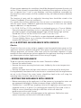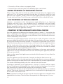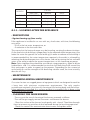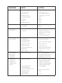
1
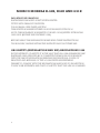
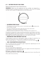
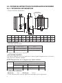
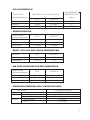
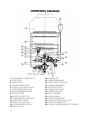
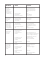
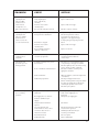
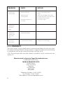
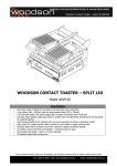
MORCO MODELS D-61B,
D-61E AND G11E
10005246
03
INDEX
A.- ENGLISH
A.1. INSTRUCTIONS FOR USERS ..........................................................................
A.2. TECHNICAL INSTRUCTIONS FOR INSTALLATION ENGINEERS .............
A.2.1. TECHNICAL INFORMATION.................................................................
A.2.2. INSTALLATION INSTRUCTIONS...........................................................
A.2.3. LOOKING AFTER THE APPLIANCE......................................................
A.2.4. SYMBOLS .................................................................................................
A.2.5. TROUBLE SHOOTING ............................................................................
A.2.6. WARRANTY..............................................................................................
5
8
8
13
17
18
18
22
B.- FRANÇAIS
B.1. INSTRUCTIONS POUR LES UTILISATEURS ..................................................
B.2. INSTRUCTIONS TECHNIQUES POUR L’INSTALLATEURS ..........................
B.2.1. DONNÉS TECHNIQUES .........................................................................
B.2.2. NORMES D’INSTALLATION ...................................................................
B.2.3. ENTRETIEN DE L'APPAREIL...................................................................
B.2.4. SYMBÔLES ...............................................................................................
B.2.5. DÉPANNAGE............................................................................................
B.2.6. GARANTIE................................................................................................
24
27
27
32
36
38
38
42
C.- NEDERLANS
C.1. INSTRUCTIES VOOR GEBRUIKERS ...............................................................
C.2. TECHNISCHE INSTRUCTIES VOOR INSTALLATIETECHNICI...................
C.2.1. TECHNISCHE INFORMATIE..................................................................
C.2.2. INSTRUCTIES VOOR DE INSTALLATIE................................................
C.2.3. ONDERHOUD VAN HET TOESTEL ............................................................
C.2.4. SYMBOLEN..............................................................................................
C.2.5. PROBLEEMOPLOSSING ........................................................................
C.2.6. GARANTIE ...............................................................................................
44
47
47
52
57
58
58
62
3
MORCO MODELS D-61B, D61E AND G11E
IMPORTANT INFORMATION
INSTANTANEOUS MULTI-POINT WATER HEATER
FITTED WITH DRAUGHT DIVERTER
FOR NORMAL OPEN FLUED SYSTEM
THIS HEATER IS MANUFACTURED IN ACCORDANCE WITH EN 26
NOTE: THIS APPLAINCE IS ADJUSTED FOR USE ON LIQUEFIED PETROLEUM
GAS ONLY (BUTANE AND PROPANE GAS)
BEFORE USING THIS APPLIANCE PLEASE READ THESE INSTRUCTIONS
THOROUGHLY, ALWAYS RETAIN THE INSTRCTIONS FOR FUTURE USE.
GAS SAFETY (INSTALLATION AND USE) REGULATIONS 1998
IN THE INTEREST OF SAFETY, IT IS THE LAW THAT ALL GAS APPLIANCES ARE
INSTALLED AND SERVICED BY A COMPETENT PERSON IN ACCORDANCE
WITH THE ABOVE REGULATIONS, BUILDING REGULATIONS, CODES OF
PRACTICE AND BYELAWS OF THE LOCAL WATER UNDERTAKING.
FAILURE TO COMPLY WITH THE REGULATIONS MAY LEAD TO PROSECTION.
IT IS IN YOUR INTERESTS AND THAT OF SAFETY THAT THE LAW IS COMPLIED
4
A.1. - INSTRUCTIONS FOR USERS
Technical instructions for use and maintenance
WARNING: Before use, this appliance must be installed and adjusted by a
competent person according the technical instructions in this manual. No attempt
must be made to adjust this appliance for use with other gases.
• LIGHTING THE PILOT
• Fully depress the control knob and turn it to the left from the ● position to the
position (pilot setting).
• The pilot should light during this operation due to the action of the
piezoelectric spark igniter or electronic ignition.
• Hold this knob in this position for about 10 seconds after the pilot has lit.
If the pilot fails to light after having activated the piezoelectric spark igniter mechanism
or electronic ignition, this means that there is air in the gas pipes. In this case, allow
plenty of time for the pipes to be cleared of air, with the gas control knob at the pilot
setting. ★ Where there are long gas pipe runs, it may take up to 3 minutes.
• PREPARING THE HEATER FOR USE
Once the pipes are free of air and the pilot is alight, wait about 10 seconds for the
safety valve mechanism to be activated, the appliance is ready for use.
Turn the control knob anti – clockwise to one of the main burner settings.
• GAS CONSUMPTION SELECTION
You can choose between two different types of operation, depending on the hot
water outlet temperature required.
Economy Setting
Turn the control knob to the position.
Use this setting only when the ambient cold water supply to the heater temperature
is high (Normally summer continental use)
Full power setting (for normal use)
Use this setting when the ambient cold water supply to the heater is low (Normally
UK or cold climate countries)
5
• WATER TEMPERATURE SELECTION
To adjust the hot water temperature, turn the selector control to the right for hotter
water and to the left for cooler water.
• Whatever the water temperature selected, it remains constant even if there are
fluctuations in the mains water pressure, (within the minimum and maximum
range), due to the action of the automatic water flow regulator.
• Never reduce the flow of hot water by using the appliance’s water inlet
stopcock. This stopcock should always be fully open.
• TURNING OFF THE WATER HEATER
From whichever position the gas control knob is in, turn it to the right to the
position. This will cut off the supply of gas to the pilot and the burner.
●
• PRECAUTIONS TO BE TAKEN AGAINST FROST AND
FREEZING CONDITIONS
If the appliance is installed in caravan holiday home, leaving the appliance undrained during freezing conditions, will result in the appliance being frost
damaged. It must be drained down in the following way:
• Turn off the mains water inlet stopcock.
• Turn temperature control knob fully anticlockwise to minimum setting.
• Turn on all hot and cold water taps.
• Open all hot and cold drain cocks on the installation. Please refer to your
caravan owners handbook for the location of all drain cocks.
• Disconnect the mains water inlet stopcock from the caravan pipework, this will
stop water refilling the pipework, if the stopcock fails due to frost damage.
• Protect drain cocks and any open ended pipe from insects or debris.
To turn the water on again, close all drain cocks, reconnect and open the mains water
inlet stopcock and turn off each hot and cold water taps as the water runs clear.
We strongly recommend a qualified & competent service engineer is employed to
do the drain down service.
MAINTENANCE RECOMMENDATIONS
The appliance must be checked for safe operation annually, regardless of frequency
of use. This refers principally to the correct combustion of the main burner and pilot.
Maintenance should only be carried out by a qualified and competent service
engineer. Please refer to section 2.3 of this manual.
6
• CHECKING FOR SAFE OPERATION
In addition to any annual service by a competent person, the user should carry out
the following checks periodically and especially after any period of disuse.
• PILOT BURNER
Look through the pilot window and check the pilot flame is blue. There should be
no yellow colour or laziness.
• MAIN BURNER
Look through the pilot window when the hot tap is open and the boiler is running.
The burner flames should be all blue with no yellow/white colour or laziness.
If you see any yellowness or laziness in the flames do not use the appliance and call
a service engineer. The burners will almost certainly be blocked by dust/fluff or
insect matter and any further use will cause sooting up leading to a dangerous
situation and expensive repair.
• OTHER INDICATIONS
• Never tamper or adjust with any pre-sealed unit.
• There is a danger of burning yourself if you touch the area in or around the
pilot window. We recommend that you avoid touching this area.
• Do not cover or use the heater for drying purposes or use the heater
compartment for storage of any goods especially flammable liquids.
• The appliance has a device to detect that combustion gases are removed
correctly via the flue. If there are any problems detected in the removal
of these gases (spillage), the device cuts off the supply of gas to the burner
N.B. Adverse weather conditions may cause this device to activate please See
section A.2.2 COMBUSTION GAS REMOVAL
To restart the appliance you must wait at least 10 minutes before
lighting the pilot light, as described earlier.
If these interruptions occur repeatedly have the heater inspected by a competent
registered gas engineer.
NEVER BLOCK ANY VENTILATION THAT HAS BEEN PURPOSELY
PROVIDED FOR THE CORRECT AND SAFE OPERATION OF THE
APPLIANCE.
7
A.2.- TECHNICAL INSTRUCTIONS FOR INSTALLATION ENGINEERS
A.2.1. TECHNICAL INFORMATION
• Shape and outer dimensions
Lower of base
G
øE
H
I.
L
B
F
Ignition window
Control knob
Temperature selector
A
WW
GAS
WW
GAS
CW
CW
J
M
C
D
A
B
C
D
E
F
G
H
I
J
L
M
310
634
230
276
110
660
115
235
464
50
456
45
D61B/D61E 266
573
190
236
90
589
97
120
350
50
344
45
G11E
• SPECIFICATIONS
• Available calorific power
MODELS
D61B - D61E
G11E
Maximum
9,4 kW (135 kcal/min.)
19,2 kW (275 kcal/min.)
Minimum
5,6 kW (81 kcal/min.)
10 kW (145 kcal/min.)
• Output in terms of a p.c.i. over 85%
• HOT WATER DELIVERY
The figures quoted are for the appliance at normal operating pressure at minimum
and maximum selector settings.
NOTE: Temperatures are in degrees rise above ambient.
SELECTOR SETTING
MODELS
D61B-D61E
OPEN
Water flow
5,4 litres/min.
T
25ºC
CLOSED
Water flow
2,7 litres/min.
T
50ºC
G11E
11 litres/min.
25ºC
5,5, litres/min.
50ºC
• OPERATING PRESSURE
• Minimum
1bar
• Maximum
10 bar
• Water inlet pressure with the appliance working at normal pressure.
8
• GAS CONSUMPTION
TIPE OF GAS
(Standarised gases)
GAS FLOWAT 15ºC and 760 mm Hg
GAS PRESSURE AT
APPLIANCE INLET
(mbar)
Butane
Propane
G11E
1,8 kg/h.
1,8 kg/h.
D61B-D61E
0,88 kg/h.
0,88 kg/h.
28-30
37
Natural
2,3 m3/h.
1,2 m3/h.
20-25
G11E
D61B-D61E
• BURNER PRESSURE
TIPE OF GAS
(Standarised gases)
Butane
27,5 mbar
29 mbar
Propane
36,3 mbar
36,9 mbar
Natural gas
16,4 mbar
19,4 mbar
• BURNT GAS FLOW AND SMOKE TEMPERATURES
MODELS
Flow g/s
Temperature
G11E
D61B-D61E
13
7,8
160ºC
137ºC
• AIR FLOW NECESSARY FOR THE COMBUSTION
TIPE OF GAS
G11E
D61B-D61E
Butane (1Kg.)
20,31 m3/h.
10,75 m3/h.
Propane (1Kg.)
20,63 m /h.
10,92 m3/h.
Natural gas (1 m3)
23,27 m3/h.
12,14 m3/h.
(Standarised gases)
3
• PIPE WORK DIAMETERS AND CONNECTION SIZES
PIPE WORK
GAS
Butane/Propane-Natural
WATER
Inlet (cold)
Outlet (hot)
Flueway
D61B and D61E
G11E
CONNECTION SIZES
10 or 15 mm.
15 mm.
15 mm.
ø 90 mm.
ø 110 mm.
9
• DESCRIPTION AND OPERATION
• These gas water heaters are equipped with:
• A stainless steel burner which can operate with Butane/Propane-Natural.
• A pilot which will operate with either Butane/Propane. Ignition is by
piezoelectric or by the battery powered electronic spark ignition.
• A fully automatic soft start ignition system which needs no adjusting. This
prevents any black smoke being given off during the main burner ignition
process.
• A thermocouple safety valve which shuts off the gas supply to both pilot and
main burner in the event of accidental flame failure.
• An inter-ignition valve which cuts off the supply of gas to the burner during the
pilot ignition process, even if there is water circulating through the appliance.
• A total shut-off valve which shuts off the supply of gas to the burner and the
pilot, even during the response time before the safety valve closes.
• A water valve which modulates the supply of gas to the burner in proportion to
the flow of water through the appliance.
• A gas economy feature which enables the supply of gas to the burner to be
reduced by up to 60%, this function can be used when the ambient
temperature of the water supply is high.
• An automatic water flow regulator to provide a constant flow rate at the tap at
varying pressures (Min supply pressure 1.0b Max supply pressure 10.0b )
• A water temperature selector.
• A heat exchanger made from pure electrolytic copper.
• A draught diverter hood.
OPERATION
Once the appliance has been turned on following the procedure given in section
A.2.2.B “Instructions for starting up the appliance” gas is supplied to the burner
whenever a hot water tap is turned on.
As water flows through the appliance a pressure differential is created within the
water control assembly. This in turn will cause the diaphragm and push rod to lift
opening the main burner gas valve
When the hot water tap is turned off, the water flow through the appliance ceases,
and the pressure differential created in the water control assembly diminishes
returning the diaphragm and push rod to the no flow position. This will allow the
main burner gas valve to close.
Whilst the appliance is in operation, even if there are pressure fluctuations in the
mains supply providing these fluctuations are within the minimum and maximum
operating pressures, the temperature of the water is maintained at all
times at the selected temperature due to the action of the “automatic water flow
regulator”
10
MORCO INSTANTANEOUS
CE 0099
GAS WATER HEATER
99AT507
Mod. Nº:
D61B
Gas Type: G-30
28mbar
G-31
37mbar Cat. I3+ 30mbar Cat. I3B/P
B11BS
Type:
Qn (hi)
11,1 kW
Qm (hi)
6,6 kW R. Fab. 20/26210
Pn
9,4 kW SERIAL Nº
Pw
10 bar
I3+
I3B/P
Cat.
Country/Pays:
GB / FR / IE / IT / ES / BE
NL
MORCO INSTANTANEOUS
CE 0099
GAS WATER HEATER
99AT507
Mod. Nº:
D61E
Gas Type: G-30
28mbar
G-31
37mbar Cat. I3+ 30mbar Cat. I3B/P
B11BS
Type:
Qn (hi)
11,1 kW
Qm (hi)
6,6 kW R. Fab. 20/26210
Pn
9,4 kW SERIAL Nº
Pw
10 bar
I3+
I3B/P
Cat.
Country/Pays:
GB / FR / IE / IT / ES / BE
NL
USE ONLY IN WELL VENTILATED ROOMS
NOT TO BE INSTALLED IN BATHROOMS
MORCO PRODUCTS LTD Morco House Riverview Road Beverley
HU17 OLD ENGLAND
USE ONLY IN WELL VENTILATED ROOMS
NOT TO BE INSTALLED IN BATHROOMS
MORCO PRODUCTS LTD Morco House Riverview Road Beverley
HU17 OLD ENGLAND
MORCO INSTANTANEOUS
CE 0099
GAS WATER HEATER
99BP819
Mod. Nº:
G11E PROP
Gas Type: G-30/G31 28-30mbar
G-30
37mbar Cat. I3+ 30mbar Cat. I3B/P
B11BS
Type:
Qn (hi)
22,6 kW
Qm (hi)
11,8 kW R. Fab. 20/26210
Pn
19,2 kW SERIAL Nº
Pw
10 bar
I3+
I3B/P
Cat.
Country/Pays:
BE / ES / FR / GB / IE / IT / PT NL
MORCO INSTANTANEOUS
CE 0099
GAS WATER HEATER
99BP819
Mod. Nº:
G11E NAT
Gas Type: G-20
20mbar
G-20/G25 20mbar Cat. I2H 25mbar Cat. I2E+
B11BS
Type:
Qn (hi)
22,6 kW
Qm (hi)
11,8 kW R. Fab. 20/26210
Pn
19,2 kW SERIAL Nº
Pw
10 bar
I2H
I2E+
Cat.
Country/Pays:
ES / GB / IE / IT / PT
BE / FR
USE ONLY IN WELL VENTILATED ROOMS
NOT TO BE INSTALLED IN BATHROOMS
MORCO PRODUCTS LTD Morco House Riverview Road Beverley
HU17 OLD ENGLAND
USE ONLY IN WELL VENTILATED ROOMS
NOT TO BE INSTALLED IN BATHROOMS
MORCO PRODUCTS LTD Morco House Riverview Road Beverley
HU17 OLD ENGLAND
MORCO INSTANTANEOUS
CE 0099
GAS WATER HEATER
99AT507
Mod. Nº:
D61B NAT
Gas Type: G-20
20mbar
G-20/G25 20mbar Cat. I2H 25mbar Cat. I2E+
B11BS
Type:
Qn (hi)
11,1 kW
Qm (hi)
6,6 kW R. Fab. 20/26210
Pn
9,4 kW SERIAL Nº
Pw
10 bar
I2H
I2E+
Cat.
Country/Pays:
ES / GB / IE / IT / PT
BE / FR
USE ONLY IN WELL VENTILATED ROOMS
NOT TO BE INSTALLED IN BATHROOMS
MORCO PRODUCTS LTD Morco House Riverview Road Beverley
HU17 OLD ENGLAND
11
1- GAS SUPPLY CONNECTION
3- GAS FILTER
4- DRAIN PLUG
5- LOWER PROTECTOR
6- WATER FLOW REGULATOR
7- WATER TEMP. SELECTOR
8- INLET PRESSURE NIPPLE
9- WATER FILTER
10- UPPER PROTECTOR
11- MAIN BURNER GAS VALVE
12- MAGNETIC VALVE
13- HI/LO GAS SETTING
14- INTER-IGNITION VALVE
15- PILOT VALVE
12
16- BURNER JET
17- MAIN BURNER BAR
18- MAIN GAS VALVE BODY
19- SPINDLE ASSEMBLY
21- PILOT INJECTOR
22- SPARK ELECTRODE
23- THERMOCOUPLE
24- PILOT BURNER
25- MAIN BURNER
26- HEAT EXCHANGER
27- DRAUGHT DIVERTER HOOD
28- PILOT SECURING NUT
29- C.P.D.S.D. (SPILAGE SAFETY DEVICE)
A.2.2. - INSTALLATION INSTRUCTIONS
• RECOMMENDATIONS
For the user
The appliance must be installed, adjusted or adapted for use with another type of
gas only by a qualified and competent person.
It is both the quality as well as the correct installation which will ensure that your
heater works properly.
For the installation engineer
A.2-2-A RELATED DOCUMENTS
The following British Standards, Codes of Practice and other Regulations must be
observed in the installation of the water heater.
The Gas Safety Regulations (Installation and Use) 1998
The Model Water Byelaws
Byelaws of the Local Water Undertaking
The Building Regulations (Permanent Buildings) England and Scotland.
BS 5482 Part 1 Installations in Permanent Dwellings
BS 5482 Part 2 Installations in Caravans and Non-Permanent Dwellings
BS 5482 Part 3 Installations in Boats
BS EN 1949 Installation of LPG System for Habitational Purposes in Leisure
Accommodation Vehicles
EN 721 Leisure Accommodation Vehicles - Ventilation Requirements
Location:
The water heater requires a plentiful supply of fresh air for correct operation. Fixed
ventilators or air inlets should not be obstructed.
Do not install the water heater in a location where incomplete combustion is
foreseeable.
IE In bathrooms or bedrooms unless specifically allowed by national legislation.
The minimum ventilation free areas are stated in this manual and must be observed.
The water heater must be fixed to a load bearing wall in a vertical plane.
The water heater should not be installed adjacent to combustible materials, either
above or at the sides or rear, if the temperature of those surfaces could otherwise
exceed 65°C based in an ambient temperature of 15°C. In such cases a heat shield
must be installed in the form of a fabrication from sheet metal mounted away from
such surfaces to allow a minimum air gap of 25 mm.
13
• COMBUSTION GAS REMOVAL
Flue: A draught diverter is fitted to the top of the water heater. The nominal flue
size is 90 mm. (D61B, D61E) and 110 mm. (G11E). In exposed situations, twinwalled flue pipe should be used. A minimum length of vertically rising flue of 600
mm. must be provided to ensure the water heaters products of combustion are
completely evacuated. If single wall flue pipe is being used which has to pass
through combustible materials, provide a metal sleeve of 115 mm. diameter which
allows an air gap of 25 mm.
The flue shall not run into chimneys for removing combustion products from solid
or liquid fuels. Flue pipes and terminals should comply with BS 715. Terminals shall
not be sited within 300 mm. of a ventilator or open window. In the U.K. full details of
flueing requirements are given in BS 5440 Part 1.
The flow rate of the combustion gases is 14 m³/h (G-30 and G-31) and 14.54 m³/h
(G-20 and G-25). The temperature of the combustion gases at the exit draught
diverter hood is 137°C (Model D61E, D61B).
The flow rate of the combustion gases is 41.4 m³/h (G-30 and G-31) and 44.4 m³/h
(G-20 and G-25). The temperature of the combustion gases at the exit draught
diverter hood is 160°C. (Model G11E).
This appliance is fitted with a safety device to monitor the removal of combustion
gases, which cuts off the supply of gas to the burner, thereby turning off the appliance.
The function of this device is to detect (thermally) if products of combustion are not
being removed to the outside air by the flue, due to adverse weather conditions
causing a down draught down the flue, blockage in the flue or problems with the
ventilation supplying the air for combustion.
This device should never be deactivated or removed, as this would compromise the
safety of the occupants in the event of flue gas spillage.
Whenever any repairs are made to this device, only original parts should be fitted.
A check should always be made to ensure that the appliance works correctly. The
procedure is as follows:
a) Turn the appliance on.
b) If air does not blow back through the flueway due to bad weather conditions
(too much wind), the control device should not stop the appliance, at least
during 30 minutes of continuous operation.
If this test is carried out satisfactorily, the appliance is in perfect operating condition.
If the appliance repeatedly turns off, this means that the combustion gases are not
being removed correctly. The problem should be resolved by taking the
appropriate steps.
• AIR SUPPLY FOR COMBUSTION
Air requirements: Reference is made to BS 5482 BS EN 1949 and EN 721 covering
ventilation requirements for permanent dwellings, caravans and boats.
Fixed ventilation should be provided to avoid draughts as far as possible without
impairing the free area of ventilation, even in adverse weather conditions. If the heater
is positioned in location which may be subjected to strong draughts i.e. close to a
window or opening then strong draughts or gusts of wind may extinguish the pilot.
14
All permanent openings for ventilation should be designed to prevent the entry of
vermin. Where screens are provided, they should not have apertures of less than 6
mm. or greater than 9 mm. in any direction, and they should be accessible for
cleaning. Fine mesh screens shall be avoided as they are liable to become blocked
with dust.
The location of vents and the method of cleaning them should be stated in the
Owners Handbook (Caravans and Boats).
As a guide, the minimum effective free area of vents is stated below in connection
with this water heater. Additional appliances burning gas in the same area would
require additional air requirements.
1. If a D61B, D61E or G11E is installed in an enclosed space in a Caravan Holiday
Home the required ventilation is that as specified in BS 5482 part 2, i.e. 10 cm²
per kilowatt input rating divided between high and low. So the high and low
should be 55.5 cm² for the D61B, D61E and 113 cm² for G11E.
2. Where a D61B or D61E is installed in an open bottomed cupboard in a
Caravan Holiday Home, i.e. in a kitchen, the ventilation requirements are as
stated in BS 5482 part 2. (EN 721).
A.2.2.B PUTTING AN APPLIANCE INTO SERVICE
Checks:
Check that the main water and gas supplies meet the specifications given on the
appliances technical specification plate. Take special care to ensure that the water
and gas pressures are correct. Also make sure that the bottle regulator is large
enough to allow sufficient gas to be supplied to the appliance, bearing in mind the
gas consumption of other appliances on the same gas supply.
• FIXING THE APPLIANCE
To do this you only need to remove the cover. Proceed as follows:
• Remove the control knobs
• Remove the screw securing the front cover, hidden by the water temperature
selector knob.
• Remove the cover from the lugs which secures it to the top of the back plate.
Having selected a location for the water heater in accordance with the requirements
set out in this Manual, the water heater should be fixed to the wall using the
mounting holes on either side of the base plate.
• PUTTING THE APPLIANCE INTO SERVICE
• Before connecting up the appliance, it will be necessary to purge the water and
gas pipework thoroughly, in order to remove filings and other debris.
• Connect the ¾ inch BSP gas coupling/ valve to the appliance, ensuring that the
supplied washer is in place. Gas jointing paste should NOT be used as this is
likely to cause a blockage to the gas inlet filter which will affect the
performance of the water heater.
• Connect the water inlet and outlet pipes to the appliance. Cold to the water
control assembly and hot to left hand side of heater.
15
• Ensure that all the washers are properly fitted.
• Ensure all gas and water joints are sufficiently tight as not to leak.
•WATER TIGHTNESS OF THE WATER CIRCUIT
Allow water to flow into the heater by slowly turning on the water supply to the
appliance. This will prevent possible damage due to hydraulic shocks on high
pressure water supplies. Purge air from the water pipes by slowly turning on all the
hot and cold water taps. Turn off the taps and check for leaks around the heater.
• GAS TIGHTNESS OF THE GAS CIRCUIT
Connect a manometer to the inlet pressure nipple (Number 8 on Operating
Diagram) and carry out a gas soundness test in accordance with the current
procedure. Gas joints down stream of the magnetic valve which cannot be tested
during soundness testing with the manometer should be checked with leak
detection fluid with the appliance running.
• STARTING UP THE APPLIANCE AND FINAL CHECKS
Start the appliance by following the directions given in section 1, “Instructions for
Users”, checking that the appliance is working correctly. Pay special attention to the
colour of the flames ensuring there is no yellowness which would indicate burner
venturis blocked by insect matter.
Check the gas operating pressures with the heater under full power at the inlet
pressure nipple located on the left hand side of the gas body valve stem (position
8 ) the pressure drop should not exceed 2.5 mb below that specified in this manual.
Check the burner pressure with the heater at full load at the test nipple located on
the left hand side of the main gas valve body below the main burner. These
pressures must at least be equal those specified in this manual in order to achieve
the desired performance specified in this manual.
Check the flue for spillage; close all doors and windows in the room containing the
appliance. If any fans are fitted within the room containing the appliance, test with
the fan or fans on full.
Light any other open flued appliances contained within the room that may affect the
flue operation.
Turn the appliance on full and run for 5 minutes to allow the flue to warm up.
Hold a smoke match in the side opening of the draught diverter using an extended
holder, making sure the end of the match is located centrally in the draught diverter.
The smoke should be pulled up the flue and not back into the room.
If spillage is detected, run the appliance for a further 10 minutes and then repeat
the test. If spillage is still detected, then check the flue for blockages, the correct
flue and terminal is fitted and the correct size of ventilation is fitted.
These gas water heaters are set in the factory for use with the gas they are intended
to burn. The gas for which each appliance is set is indicated on the packaging and
on the cover of the heater itself.
Note: The jets to be used with the type of gas for which the appliance is intended will be
supplied from the factory. Their diameters correspond to the following sizes: Ø in mm
16
ø in mm.
MODELS
GAS TYPE
BURNER
PILOT
PROP/BUTANE
0,72 (6 off)
0,19
D61B
Natural
1,35 (6 off)
0,32
G11E
PROP/BUTANE
0,72 (12 off)
0,19
G11E
Natural
1,18 (12 off)
0,32
D61B-D61E
A.2.3. - LOOKING AFTER THE APPLIANCE
• PRECAUTIONS
- Against furring up (lime scale)
If the appliance is installed in an area with very hard water, with time, the following
may occur:
- A fall in the hot water temperature, or
- A reduction in the hot water flow.
This means that the heat exchanger may be furred up, creating the above situations.
As the level of scale build up is proportional to the selected outlet temperature, (the
hotter the water the greater the scale build up) In order to reduce scale build up it
is recommended that the water temperature required at the outlet is achieved by
selecting the desired temperature at the heater, and not by mixing the hot and cold
water at the outlet to obtain the correct temperature i.e. for showering purposes.
Note: Defurring/descaling should be carried out using proprietary agent or dilute
hydrochloric acid. It is recommended to circulate the descaling fluid around the
heat exchanger in order to speed up the process. Depending on the amount of
scale build up and the strength of the descaling solution used, the time to totally
descale will vary.
• MAINTENANCE
• MINIMUM ANNUAL MAINTENANCE
Gas water heaters are rugged pieces of equipment which are designed to work for
a long time with minimum maintenance requirements. The only regular
maintenance required is the (annual) cleaning of the heating body and the burner.
If the appliance is installed in a caravan or boat it is essential this is done at the
beginning of each season.
• CLEANING THE MAIN BURNER
- To carry out the annual cleaning of the burner, proceed as follows:
- Turn off the gas supply, remove the cover and remove the burner.
- Clean the surface of the burner heads gently with a brush. Then blow through
them to remove any particles of dust loosened during the brushing operation.
- Check the venturis for contamination from insects and spiders webs.
17
• CLEANING THE HEAT EXCHANGER
To carry out the annual cleaning of the heating body, proceed as follows:
- Turn off the gas supply
- Turn off the supply of water to the appliance by turning off the appliance’s
water inlet tap.
- Turn on all the hot water taps to empty all the pipes.
- Remove the heating body and clean it by gently brushing the fins. Soot if found
should be removed by washing, and the cause of the sooting investigated.
• CLEANING THE PILOT
If the pilot light flame is yellow and the safety valve takes a long time to open, this
means that either the pilot injector or pilot burner is partially blocked.
The pilot injector may be blocked with contaminants carried within the gas, whilst
the pilot burner is more likely to be contaminated by insects (spiders / egg sacs)
N.B. No attempt should be made to clear blocked or partially blocked pilot
injectors by using wire. If blowing through the injector fails to clear the
restriction, then a new injector should be fitted.
When the pilot is working normally the flame should be a stable blue coloured cone
shape. To clean the pilot burner, proceed as follows:
- Turn off the gas supply, remove the front cover. Remove the pilot injector, by
slackening the supply pipe nut first, and unscrewing the pilot injector from the
pilot burner
- Remove the contamination from within the pilot burner using wire, and blow
through to remove any further debris.
- Replace the pilot injector, ensuring that the washers are properly fitted and test
joints with leak detection fluid.
A.2.4. SYMBOLS
The meanings of the symbols used on the appliance and on the packaging are as follows:
Cat
: Appliance category
Qn
: Nominal gas flow rate according to Hi
Qm
: Minimum gas flow rate according to Hi
Hi
: Net calorific value
A.2.5 TROUBLE SHOOTING
Majority of the problems you will come across are usually caused by either gas supply,
water supply, air supply or contamination of either!
Always carry out basic performance tests including operating pressure
tests before jumping to the troubleshooting chart.
Be sure you are getting an accurate description of the symptoms before
concluding the water heater is at fault. The charts assume a level of knowledge and
competency and are there to serve as a guide and a prompt.
18
PROBLEM
No spark.
Pilot fails to light.
Pilot is difficult to
light with spark.
CAUSE
ACTION
The piezo electric ignitor is faulty.
Replace with new one.
Electrode is fractured.
Replace with new one.
Electrode is dirty.
Clean it with bristle brush, etc.
Spark gap is too wide.
Adjust the gap to 3.2-4.0mm.
Incorrect battery polarity.
Check.
Poor earth.
Check.
Flat battery.
Check.
Spark generator faulty.
Check.
Blocked injector.
Clean using soft bristle only.
No gas supply.
Check.
The pilot injector is clogged.
Clean or replace pilot jet.
Air in gas line.
Depress the control button to
ignition position long enough to
expel all air.
Purge gas supply through hob.
Pilot ignites but
fails to stay alight.
The flame on pilot burner does
not impinge on the
thermocouple correctly.
Clean or replace pilot jet.
Re-position thermocouple.
Loose thermocouple.
Check thermocouple for tightness.
Magnetic valve is faulty.
Replace with new one.
Faulty thermocouple.
Replace with new one.
The main control button is not
fully depressed.
Press it down hard and hold that
position for about 10 seconds.
C.P.D.S.D is faulty.
Replace it.
When main burner
ignites, the pilot
flame becomes
much smaller.
Insufficient gas pressure.
Check operating pressure at
burner and inlet. Check the whole
gas supply line for blockages,
including gas filter on the heater.
Main burner does
not ignite even
though hot water
outlets have been
turned on.
Insufficient water pressure.
Check water pressure at inlet to
heater. Check for blockages in
supply line or hot pipes, taps,
shower hoses and heads. If using
a pump, check pump for faults.
Faulty diaphragm in water
control body assembly.
Renew diaphragm.
Hot and cold water pipes crossed.
Check, re-connect correctly.
Contamination in water
control assembly.
Clean.
Water filter blocked.
Clean.
19
PROBLEM
Main Burner ignites
when temp.
adjusting knob is
positioned at
“HOT” but goes out
when turned down
to “WARM” position.
CAUSE
Insufficient water pressure
Check water pressure at inlet to
heater. Check for blockages in
supply line or hot pipes and taps.
If using a pump, check pump for
faults.
Water filter is clogged.
Clean.
Faulty diaphragm.
Renew diaphragm.
Restriction in heat exchanger
Descale or replace.
Main burner fails to
shut off when hot
water taps are
closed.
Dirt on main gas valve seating.
Jammed water regulator.
Contamination in water
control assembly.
Inspect and clean.
Inspect and clean.
Clean or replace.
Main burner flames
are yellow and lazy.
NB Yellow tips on
blue flame may be
normal if appliance
is running on butane.
Partly blocked burner venturis.
(Insects and spiders).
Gas flow rate too high.
Remove main burner and clean as
necessary using stiff brush.
Check gas pressure at the heater
and adjust regulator to the correct
range.
Clean the heat exchanger.
On ignition, the
The position between pilot
burner and main burner is
not close enough.
Gas pressure (flow rate) is
insufficient.
burner makes an
unusual noise.
(Flash-back).
Heat exchanger sootted up and
dirty.
Gas supply line is too small
in diameter. (Insufficient
gas supply).
Partly blocked main burner
Injectors.
Even though temp.
adjusting knob is
turned to “HOT”
position, heated
water is not hot
enough.
20
ACTION
Gas pressure (flow rate) is
insufficient.
Gas supply line is too small
in diameter. (Insufficient
gas supply).
Partly blocked main burner
injectors.
Low water pressure.
Adjust.
Check operating pressure’s at the
burner and inlet pressure test points. Check
the whole gas supply line for blockages
including the gas filter on the heater.
Check the gas regulator.
Enlarge the gas supply pipe.
Clean them.
Check gas cylinder regulator for
faults and the supply pipe for
blockages.
Enlarge the gas supply pipe.
Clean them.
Check for restrictions. Improve
pressure at mains.
PROBLEM
CAUSE
ACTION
Even though temp.
adjusting knob is
turned to“HOT”
Position, heated
water is not hot
enough due to too
high a water flow rate.
Water regulator is faulty.
Faulty diaphragm in
water control body
assembly.
Incorrect water control
assembly fitted.
Hot and cold water pipes crossed.
Inspect and clean.
Replace with new one.
Even though temp.
adjusting knob is
turned to “WARM”
position, heated
water is too hot due
to a low water flow rate.
Water regulator is faulty.
Water pressure is insufficient.
Inspect and replace it.
Check water pressure at inlet to
heater. Check for blockages in
supply line or hot pipes and taps.
If using a pump, check pump for faults.
Clean.
Replace with correct type.
Water filter is clogged.
Incorrect water control
assembly fitted.
Heat exchanger restriction
(damage or limescale)
Replace with correct type.
Check, re-connect correctly.
Replace or descale.
Same as the above
conditions due to
long flame.
Too much volume of gas flow/
excessive gas pressure.
Check gas pressure at the heater
and adjust regulator within the
correct range.
Main burner and
pilot flame goes out
during operation.
Combustion spillage safety device
has activated.
Check flue for correct fitting, blockages
or any damage to flue pipe or terminal.
Check for spillage due to the effects of any
fans or adverse weather conditions.
Check the ventilation, referring to the
appropriate standard.
None or insufficient ventilation fitted.
Blocked ventilation
Insufficient gas pressure.
Main burner only
goes out during
operation.
Gas pressure (flow rate) is
insufficient.
Gas supply line is too small in
diameter. (Insufficient gas
supply).
Partly blocked main burner
injectors.
Low water pressure and
reduced flow rate due to other
cold water outlets in use at
same time as heater.
Water filter blocked.
Diaphragm faulty.
Unblock ventilation, (advise the importance
of ventilation).
Check operating pressure’s at the
burner and inlet pressure test points. Check
the whole gas supply line for blockages
including the gas filter on the heater.
Check the gas regulator.
Check gas cylinder regulator for
faults and the supply pipe for
blockages.
Enlarge the gas supply pipe.
Clean them.
Check water pressure at inlet with
water heater in operation.
Plumbing modifications may be
necessary to installation.
Clean or replace.
Replace diaphragm.
21
PROBLEM
Water heater
operates at taps
but not at shower.
CAUSE
ACTION
Shower hose too small or kinked.
Shower head restricted.
Replace.
Descale, remove blanking rings or
replace.
Restrict cold water supply to shower mixer.
Set shower temperature at water heater rather
than mixing cold water at mixer.
Set correctly or replace
High water pressure.
Low water pressure.
Shower mixer tap faulty or not
set correctly.
Water control
assembly leaks
from between
flanges.
Frost damage.
Replace damaged parts.
Water control
assembly leaks
at spindle, outlet
union, or inlet
union.
Frost damage or
contamination of O rings.
Clean or replace.
Soot deposits on
front cover and
smell of fumes.
Blocked burner venturi and
sooted blocked heat exchanger.
Remove burner and heat
exchanger and clean thoroughly.
A.2.6. WARRANTY
The water heater is guaranteed against manufacturing defects for one year from
first commissioning. However the guarantee is subject to proof of commissioning
in accordance with the gas safety (Installation and Use) act of
1998. The guarantee does not cover defects caused by lack of maintenance see
section 2.3.
Manufactured in Spain by Fagor Electrodomésticos.
Distributed in the U.K. by:
MORCO PRODUCTS LTD
Morco House
Riverview Road
Beverley
East Yorkshire
HU17 0LD
ENGLAND
Telephone Number: 01482 325456
Fax Number: 01482 212869
Web Address: www.morcoproducts.co.uk
22