1
FACSIMILE EQUIPMENT
SERVICE MANUAL
MODEL: FAX2800/MFC4800
© Copyright Brother 2001
All rights reserved.
No part of this publication may be reproduced in any
form or by any means without permission in writing
from the publisher.
Specifications are subject to change without notice.
PREFACE
This publication is a Service Manual covering the specifications, construction, theory of operation,
and maintenance of the Brother facsimile equipment. It includes information required for field
troubleshooting and repair--disassembly, reassembly, and lubrication--so that service personnel
will be able to understand equipment function, to rapidly repair the equipment and order any
necessary spare parts.
To perform appropriate maintenance so that the facsimile equipment is always in best condition
for the customer, the service personnel must adequately understand and apply this manual.
This manual is made up of six chapters and appendices.
CHAPTER 1
GENERAL DESCRIPTION
CHAPTER 2
INSTALLATION
CHAPTER 3
THEORY OF OPERATION
CHAPTER 4
DISASSEMBLY/REASSEMBLY AND LUBRICATION
CHAPTER 5
MAINTENANCE MODE
CHAPTER 6
ERROR INDICATION AND TROUBLESHOOTING
Appendix 1.
EEPROM Customizing Codes
Appendix 2.
Firmware Switches (WSW)
Appendix 3.
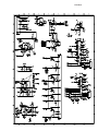
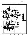
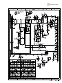
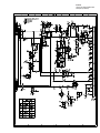
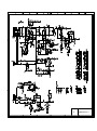
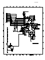
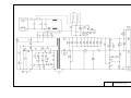
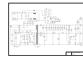
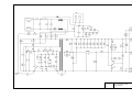
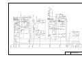
Circuit Diagrams
This manual describes the models and their versions to be destined for major countries. The specifications
and functions are subject to change depending upon each destination.
SAFETY INFORMATION
Laser Safety (110-120V Model only)
This printer is certified as a Class 1 laser product under the US Department of Health and Human
Services (DHHS) Radiation Performance Standard according to the Radiation Control for Health
and Safety Act of 1968. This means that the printer does not produce hazardous laser radiation.
Since radiation emitted inside the printer is completely confined within the protective housings and
external covers, the laser beam cannot escape from the machine during any phase of user
operation.
CDRH Regulations (110-120V Model only)
The Center for Device and Radiological Health (CDRH) of the US Food and Drug Administration
implemented regulations for laser products on August 2, 1976. These regulations apply to laser
products manufactured from August 1, 1976. Compliance is mandatory for products marketed in
the United States. The label shown below indicates compliance with the CDRH regulations and
must be attached to laser products marketed in the United States.
The label for Chinese products
MANUFACTURED:
JUNE
2001
BROTHER CORP. (ASIA) LTD.
BROTHER BUJI NAN LING FACTORY
Gold Garden Industry, Nan Ling Village, Buji,
Rong Gang, Shenzhen, China.
This product complies with FDA radiation
performance standards, 21 CFR Subchapter J.
C
CHAPTER 1
GENERAL DESCRIPTION
CHAPTER 1 GENERAL DESCRIPTION
CONTENTS
1.1
1.2
EQUIPMENT OUTLINE ...................................................................................................1-1
1.1.1
External Appearance and Weight ........................................................................1-1
1.1.2
Components .........................................................................................................1-1
SPECIFICATIONS............................................................................................................1-2
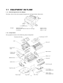
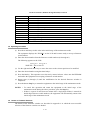
1.1 EQUIPMENT OUTLINE
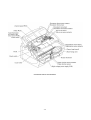
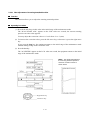
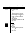
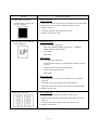
1.1.1 External Appearance and Weight
The figure below shows the equipment appearance and approximate dimensions.
(H)
243 mm
9.6"
(W)
395 mm
15.6"
(including handset)
Weight:
(D)
359 mm
14.1"
Machine proper
Machine (incl. drum unit & toner cartridge)
In package
1.1.2 Components
The equipment consists of the following major components:
1 -1
Approx. 7.5 kg
Approx. 8.7 kg
Approx. 11 kg
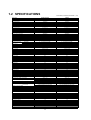
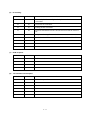
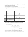
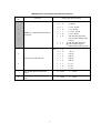
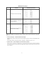
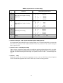
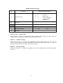
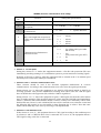
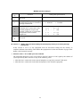
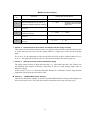
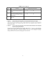
1.2 SPECIFICATIONS
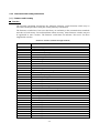
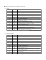
FAX2800 (FAX2850)/FAX2900 (1/2)
Model Name
GENERAL
Print Engine
Modem Speed(bps)
Transmission Speed(sec.)
ITU-T Group
Coding Method
Input/Output Width
Input/Output Length
ADF(pages)
LCD Size
LCD Backlight
Backup Clock
Memory Capacity (physical)
Optional Memory
Dimensions w/ Carton (WxDxH)
Dimensions w/o Carton (WxDxH)
Weight w/ Carton
Weight w/o Carton
Color
Operating Environment
Temperature
Humidity
Power Source
Power Consumption (Sleep/Standby/Peak)
On/Off Switch
Starter Toner
Warm Up Time
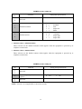
TELEPHONE
Handset
One-Touch Dial
Speed Dial
Speaker Phone
Chain Dialing
Caller ID
Call Waiting Caller ID
Distinctive Ringing
Call Manage
Hold/Mute Key
Power Failure Dialing
Speaker Volume
Ring Volume
Handset Volume
PBX Feature
Transfer Method
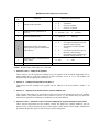
FAX
Internet FAX
Easy Receive/Fax Detect
Fax/Tel Switch
Enhanced Remote Activate
Scan Speed (sec./page, A4:Standard)
Memory Transmission
(Brother#1 Chart)
(ITU-T Chart)
Broadcasting
Auto Reduction
Out-of-Paper Reception
(Brother #1 Chart)
(ITU-T Chart)
ECM(Error Correction Mode)
Group Dial
Color FAX (Document Send/Receive)
Color FAX (Memory Send/Receive)
Memory Backup
LIST/REPORT
Activity Report/Journal Report
Transmission Verification Report
INTERFACE
External TAD Interface
Host Interface (Serial)
Host Interface (IEEE1284)
Host Interface (USB)
LAN Interface
Acceptable Media Card Slot
Analog Video Port
FAX2800 (FAX2850)
FAX2900
Laser (YL4)
Laser (YL4)
14,400(Fax)
6(Brother#1,MMR)
G3
MH/MR/MMR
5.8"-8.5"/3.5"-8.5"
5"-14"/5"-14"
up to 20
16 Characters
No
Yes (1 hour)
2MB (RAM)
N/A
519mm x 454 mm x 375 mm
395mm x 359mm x 243mm
11 Kg
7.5 Kg
Gray 1495
5 - 32.5 degrees Centigrade
20 - 80 %
120 VAC, 50/60Hz
10W/ 70W/ 940W or less
No
Yes (1,000 pages)
Approx. 12 sec
14,400(Fax)
6(Brother#1,MMR)
G3
MH/MR/MMR
5.8"-8.5"/3.5"-8.5"
5"-14"/5"-14"
up to 20
16 Characters x 1 Line
No
Yes (1 hour)
4MB (RAM)
N/A
519mm x 454 mm x 375 mm
395mm x 359mm x 243mm
11 Kg
7.5 Kg
Gray 1495
5 - 32.5 degrees Centigrade
20 - 80 %
120 VAC, 50/60Hz
10W/ 70W/ 940W or less
No
Yes (1,000 pages)
Approx. 12 sec
Yes
8
100
N/A
Yes
Yes
Yes
Yes
Yes
Yes
N/A
Yes (3 steps + OFF)
Yes (3 steps + OFF)
Yes (2 steps + OFF + Amplify)
N/A
No
Yes
8
120
N/A
Yes
Yes
Yes
Yes
Yes
Yes
N/A
Yes (3 steps + OFF)
Yes (3 steps + OFF)
Yes (2 steps + OFF + Amplify)
N/A
No
N/A
Yes
Yes
Yes
Approx. 3.5
90 Pages(MMR/Standard Resolution)
80 Pages(MMR/Standard Resolution)
Yes (158 locations)
Yes
90 Pages(MMR/Standard Resolution)
80 Pages(MMR/Standard Resolution)
Yes
Yes (6)
No / No
No / No
No
N/A
Yes
Yes
Yes
Approx. 3.5
220 Pages(MMR/Standard Resolution)
240 Pages(MMR/Standard Resolution)
Yes (178 locations)
Yes
220 Pages(MMR/Standard Resolution)
240 Pages(MMR/Standard Resolution)
Yes
Yes (6)
No / No
No / No
Yes
Yes (up to 200)
Yes
Yes (up to 200)
Yes
Yes
No
No
No
No
N/A
N/A
Yes
No
Yes
Yes
No
N/A
N/A
1 -2
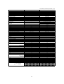
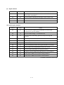
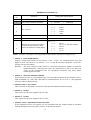
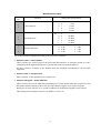
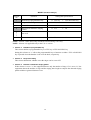
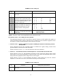
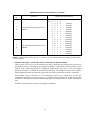
FAX2800 (FAX2850)/FAX2900 (2/2)
Model Name
PRINTER
Color/Mono
Engine Type
Resolution(dpi)
Speed(ppm)
Paper Capacity(sheets)
Output Paper Capacity(sheets)
Standard Print Language
Emulation
Resident Fonts
Fonts Disk Based
Paper Handling Size
Manual Feed Slot
Other Paper Type
Sheet Weight
(Paper Cassette)
(Manual Slot)
Printer Driver
COPY
Color/Mono
Speed(ppm)
Multi Copy(Stack)
Multi Copy(Sort)
Reduction/Enlargement(%)
Resolution(dpi)
First Copy Out Time (From Ready Mode)
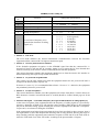
SCANNER
Color/Mono
Resolution(Optical : dpi)
Resolution(Int. : dpi)
Gray Scale
TWAIN Compliant & Operating System
PCI Scanner (Parallel/Serial)
BUNDLED SOFTWARE (For Windows)
Printer Driver
TWAIN
Viewer
Formats (Import)
Formats (Export)
Pop Up Menu
OCR
PC Fax
Remote Setup
PC Diagnostics
Others
BUNDLED SOFTWARE (For iMAC)
Printer Driver
TWAIN
Viewer
Formats (Import)
Formats (Export)
Pop Up Menu
OCR
PC Fax
Remote Setup
PC Diagnostics
Others
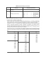
ACCESSORY
Life / Yield
Toner Starter (N/A)
Supply (TN-250)
Drum
(DR-250)
FAX2800 (FAX2850)
FAX2900
-
Mono
Laser (YL4)
600x600
up to 10
200
50
Windows GDI
No
No
No
LTR, LGL, A4, B5, A5, EXE
N/A
OHP, Envelopes, Organizer
64-105 g/m2 (17 - 28 lb)
N/A
Win95/98/98SE/Me/2000Professional/
NT4.0WS
Mono
up to 10
Yes
No
50 to 200 in 1% increments
200 x 300
Approx. 13 sec.
Mono
up to 10
Yes
No
50 to 200 in 1% increments
200 x 300
Approx. 13 sec.
No
-
No
-
-
-
No
No
No
No
No
No
No
No
-
Available download from Web
No
No
No
No
No
No
No
-
No
No
No
No
No
No
No
No
-
No
No
No
No
No
No
No
No
-
1,000 pages
2200 pages
20,000 pages: Continuous Printing
8,000 pages:1 page/job
1,000 pages
2200 pages
20,000 pages: Continuous Printing
8,000 pages:1 page/job
1 -3
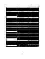
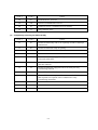
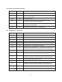
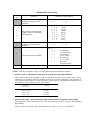
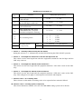
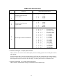
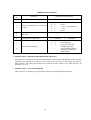
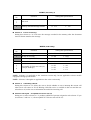
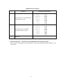
MFC4800/FAX3800 (1/2)
Model Name
GENERAL
Print Engine
Modem Speed(bps)
Transmission Speed(sec.)
ITU-T Group
Coding Method
Input/Output Width
Input/Output Length
ADF(pages)
LCD Size
LCD Backlight
Backup Clock
Memory Capacity (physical)
Optional Memory
Dimensions w/ Carton (WxDxH)
Dimensions w/o Carton (WxDxH)
Weight w/ Carton
Weight w/o Carton
Color
Operating Environment
Temperature
Humidity
Power Source
Power Consumption (Sleep/Standby/Peak)
On/Off Switch
Starter Toner
Warm Up Time
TELEPHONE
Handset
One-Touch Dial
Speed Dial
Speaker Phone
Chain Dialing
Caller ID
Call Waiting Caller ID
Distinctive Ringing
Call Manage
Hold/Mute Key
Power Failure Dialing
Speaker Volume
Ring Volume
Handset Volume
PBX Feature
Transfer Method
FAX
Internet FAX
Easy Receive/Fax Detect
Fax/Tel Switch
Enhanced Remote Activate
Scan Speed (sec./page, A4:Standard)
Memory Transmission
(Brother#1 Chart)
(ITU-T Chart)
Broadcasting
Auto Reduction
Out-of-Paper Reception
(Brother #1 Chart)
(ITU-T Chart)
ECM(Error Correction Mode)
Group Dial
Color FAX (Document Send/Receive)
Color FAX (Memory Send/Receive)
Memory Backup
LIST/REPORT
Activity Report/Journal Report
Transmission Verification Report
INTERFACE
External TAD Interface
Host Interface (Serial)
Host Interface (IEEE1284)
Host Interface (USB)
LAN Interface
Acceptable Media Card Slot
Analog Video Port
MFC4800
FAX3800
Laser (YL4)
Laser (YL4)
14,400(Fax)
6(Brother#1,MMR)
G3
MH/MR/MMR
5.8"-8.5"/3.5"-8.5"
5"-14"/5"-14"
up to 20
16 Characters x 1 Line
No
Yes (1 hour)
2MB (RAM)
N/A
519mm x 454 mm x 375 mm
395mm x 359mm x 243mm
11 Kg
7.5 Kg
Gray 1495
5 - 32.5 degrees Centigrade
20 - 80 %
120 VAC, 50/60Hz
10W/ 70W/ 940W or less
No
Yes (1,000 pages)
Approx. 12 sec
33,600(Fax)
2(Brother#1,JBIG)
Supper G3
MH/MR/MMR/JBIG
5.8"-8.5"/3.5"-8.5"
5"-14"/5"-14"
up to 20
16 Characters x 1 Line
Yes
Yes (1 hour)
8MB (RAM)
N/A
519mm x 454 mm x 375 mm
395mm x 359mm x 243mm
11 Kg
7.5 Kg
Gray 1495
5 - 32.5 degrees Centigrade
20 - 80 %
120 VAC, 50/60Hz
10W/ 70W/ 940W or less
No
Yes (1,000 pages)
Approx. 12 sec
Yes
No
100
N/A
Yes
Yes
Yes
Yes
Yes
Yes
N/A
Yes (3 steps + OFF)
Yes (3 steps + OFF)
Yes (2 steps + OFF + Amplify)
N/A
No
Yes
8
120
N/A
Yes
Yes
N/A
Yes
Yes
Yes
N/A
Yes (3 steps + OFF)
Yes (3 steps + OFF)
Yes (2 steps + OFF + Amplify)
N/A
No
N/A
Yes
Yes
Yes
Approx. 3.5
90 Pages(MMR/Standard Resolution)
80 Pages(MMR/Standard Resolution)
Yes (150 locations)
Yes
90 Pages(MMR/Standard Resolution)
80 Pages(MMR/Standard Resolution)
Yes
Yes (6)
No / No
No / No
No
N/A
Yes
Yes
Yes
Approx. 3.5
600 Pages(MMR/Standard Resolution)
400 Pages(MMR/Standard Resolution)
Yes (178 locations)
Yes
600 Pages(MMR/Standard Resolution)
400 Pages(MMR/Standard Resolution)
Yes
Yes (6)
No / No
No / No
Yes
Yes (up to 200)
Yes
Yes (up to 200)
Yes
Yes
No
Yes
Yes
No
N/A
N/A
Yes
No
Yes
Yes
No
N/A
N/A
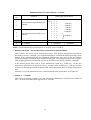
1 -4
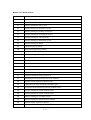
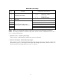
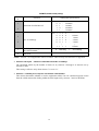
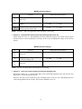
MFC4800/FAX3800 (2/2)
Model Name
PRINTER
Color/Mono
Engine Type
Resolution(dpi)
Speed(ppm)
Paper Capacity(sheets)
Output Paper Capacity(sheets)
Standard Print Language
Emulation
Resident Fonts
Fonts Disk Based
Paper Handling Size
Manual Feed Slot
Other Paper Type
Sheet Weight
(Paper Cassette)
(Manual Slot)
Printer Driver
COPY
Color/Mono
Speed(ppm)
Multi Copy(Stack)
Multi Copy(Sort)
Reduction/Enlargement(%)
Resolution(dpi)
First Copy Out Time (From Ready Mode)
SCANNER
Color/Mono
Resolution(Optical : dpi)
Resolution(Int. : dpi)
Gray Scale
TWAIN Compliant & Operating System
PCI Scanner (Parallel/Serial)
BUNDLED SOFTWARE (For Windows)
Printer Driver
TWAIN
Viewer
Formats (Import)
Formats (Export)
Pop Up Menu
OCR
PC Fax
Remote Setup
PC Diagnostics
Others
BUNDLED SOFTWARE (For iMAC)
Printer Driver
TWAIN
Viewer
Formats (Import)
Formats (Export)
Pop Up Menu
OCR
PC Fax
Remote Setup
PC Diagnostics
Others
ACCESSORY
Life / Yield
Toner Starter (N/A)
Supply (TN-250)
Drum
(DR-250)
MFC4800
FAX3800
Mono
Laser (YL4)
600x600
up to 10
200
50
Windows GDI
No
No
Yes
LTR, LGL, A4, B5, A5, EXE
N/A
OHP, Envelopes, Organizer
64-105 g/m2 (17 - 28 lb)
N/A
Win95/98/98SE/Me/2000Professional/
NT4.0WS MacOS 8.5-9.1
Mono
Laser (YL4)
600x600
up to 10
200
50
Windows GDI
No
No
No
LTR, LGL, A4, B5, A5, EXE
N/A
OHP, Envelopes, Organizer
64-105 g/m2 (17 - 28 lb)
N/A
Win95/98/98SE/Me/2000Professional/
NT4.0WS
Mono
up to 10
Yes
No
50 -- 200 in 1% increments
200 x 300
Approx. 13 sec.
Mono
up to 10
Yes
No
50 -- 200 in 1% increments
200 x 300
Approx. 13 sec.
Yes
Mono
200x400
1,200x1,200
256
Win95/98/98SE/Me/NT4.0/2000Professinal
MacOS 8.6-9.1
Parallel/USB
No
-
Yes
Yes
Yes
TIFF/BMP/PCX/DCX/BTF/BTX/MAX
TIFF/BMP/MAX
Yes
Yes
Yes (TX only)
Yes
No
Auto E-mail Printing(Win 95/98/Me only)
Available download from Web
No
No
No
No
No
No
No
-
Yes
Yes
Yes
TIFF/BMP/PCX/DCX/BTF/BTX/MAX
TIFF/BMP/MAX
No
Yes
Yes
No
No
-
No
No
No
No
No
No
No
No
-
1,000 pages
2200 pages
20,000 pages: Continuous Printing
8,000 pages:1 page/job
1,000 pages
2200 pages
20,000 pages: Continuous Printing
8,000 pages:1 page/job
1 -5
-
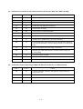
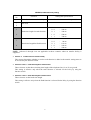
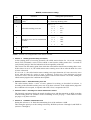
FAX-8070P/MFC-9070 (1/2)
Model Name
GENERAL
Print Engine
Modem Speed(bps)
Transmission Speed(sec.)
ITU-T Group
Coding Method
Input/Output Width
Input/Output Length
ADF(pages)
LCD Size
LCD Backlight
On-Screen Programming
Backup Clock
Memory Capacity(physical)
Memory Backup
Optional Memory
Dimensions w/ Carton (WxDxH)
Dimensions w/o Carton (WxDxH)
Weight w/ Carton
Weight w/o Carton
Color
Operating Environment Temperature
Humidity
Power Source
Power Consumption (Sleep/Standby/Peak)
On/Off Switch
Starter Toner
TELEPHONE
Handset
One-Touch Dial
Speed Dial
Speaker Phone
Chain Dialing
Caller ID
Call Waiting Caller ID
Distinctive Ringing
Hold/Mute Key
Power Failure Dialing
Speaker Volume
Ring Volume
Handset Volume
PBX Feature
Transfer Method
FAX
Internet FAX
Easy Receive/Fax Detect
Fax/Tel Switch
Enhanced Remote Activate
Quick-Scan(Memory transmission)
Memory Transmission
(Brother#1 Chart)
(ITU-T Chart)
Broadcasting
Manual Broadcasting
Auto Reduction
Out-of-Paper Reception (Brother #1 Chart)
(ITU-T Chart)
ECM(Error Correction Mode)
Color FAX (Document Send/Receive)
Color FAX (Memory Send/Receive)
LIST/REPORT
Activity Report/Journal Report
Transmission Verification Report
INTERFACE
External TAD Interface
Host Interface (Serial)
Host Interface (IEEE1284)
Host Interface (USB)
LAN Interface
Acceptable Media Card Slot
Analog Video Port
FAX-8070P
MFC-9070
Laser (YL4)
14,400(Fax)
Approx.6 (Brother#1,MMR)
G3
MH/MR/MMR
5.8"-8.5"/3.5"-8.5"
5"-14"/5"-14"
up to 20
16 Characters x 1 line
Yes
Yes
Yes (9 hours)
2 MB(RAM)
Yes ( Max. 4 days )
N/A
519mm x 454 mm x 375 mm
395mm x 359mm x 243mm
11 Kg
7.5 Kg
Gray 1495
5 - 32.5 degrees Centigrade
20 - 80 %
220-240 VAC, 50/60Hz
10W/70W/940W or less
No
No
Laser (YL4)
14,400(Fax)
Approx.6(Brother#1,MMR)
G3
MH/MR/MMR
5.8"-8.5"/3.5"-8.5"
5"-14"/5"-14"
up to 20
16 Characters x 1 line
Yes
Yes
Yes (9 hours)
8 MB(RAM)
Yes ( Max. 4 days )
N/A
519mm x 454 mm x 375 mm
395mm x 359mm x 243mm
11 Kg
7.5 Kg
Gray 1495
5 - 32.5 degrees Centigrade
20 - 80 %
220-240 VAC, 50/60Hz
10W/70W/940W or less
No
No
No
8 locations
100
N/A
Yes
N/A
N/A
Yes(UK, DEN only)
N/A
N/A
Yes (3 steps + OFF)
Yes (3 steps + OFF)
N/A
Yes
Flash/Earth for UK/Netherlands
No
No
100
N/A
Yes
N/A
N/A
Yes(UK, DEN only)
N/A
N/A
Yes (3 steps + OFF)
Yes (3 steps + OFF)
N/A
Yes
Flash/Earth for UK/Netherlands
N/A
Yes
Yes
Yes
Yes as default, Approx.3.5 sec./page (A4 standard)
90 Pages(MMR/Standard Resolution)
80 Pages(MMR/Standard Resolution)
Yes (158 locations)
Yes(50 locations )
Yes
90 Pages(MMR/Standard Resolution)
80 Pages(MMR/Standard Resolution)
Yes
No / No
No / No
N/A
Yes
Yes
Yes
Yes as default, Approx.3.5 sec./page (A4 standard)
500 Pages(MMR/Standard Resolution)
400 Pages(MMR/Standard Resolution)
Yes (150 locations)
Yes ( 50 locations )
Yes
500 Pages(MMR/Standard Resolution)
400 Pages(MMR/Standard Resolution)
Yes
No / No
No / No
Yes (up to 200)
Yes
Yes (up to 200)
Yes
Yes
No
No
No
No
N/A
N/A
Yes
No
Yes
Yes
No
N/A
N/A
1 -6
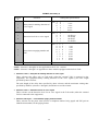
FAX-8070P/MFC-9070 (2/2)
Model Name
PRINTER
Color/Mono
Engine Type
Resolution(dpi)
Speed(ppm)
Paper Capacity(sheets)
Additional Paper Capacity(sheets)
Output Paper Capacity(sheets)
Standard Print Language
Emulation
FAX-8070P
MFC-9070
-
Resident Fonts
-
Fonts Disk Based
Paper Handling Size
Manual Feed Slot
Other Paper Type
Sheet Weight
(Paper Cassette)
(Manual Slot)
Printer Driver
-
Mono
Laser (YL4)
600x600
up to 10
200
No
50
Windows GDI
Yes(PCL5e)
Yes(Bitmap font: LetterGothic16.66, OCR-A, OCR-B,
Scaleable font; 49 fonts )
Yes
LTR, LGL, A4, B5, A5, EXE
N/A
OHP, Envelopes, Organizer
64-105 g/m2 (17 - 28 lb)
N/A
Win95/98/98SE/Me,
WinNT4.0WS/2000Professional
Mono
up to 10
Yes
No
50 to 200 in 1% increments
200 x 300
Mono
up to 10
Yes
Yes
50 to 200 in 1% increments
200 x 300
SCANNER
Color/Mono
Resolution(Optical : dpi)
Resolution(Int. : dpi)
Gray Scale
TWAIN Compliant & Operating System
-
PCI Scanner (Parallel/Serial)
-
Mono
200x400
1,200x1,200
256
Win95/98/98SE/Me,
WinNT4.0WS/2000Professional
Parallel/USB
BUNDLED SOFTWARE (For Windows)
Printer Driver
TWAIN
Viewer
Pop Up Menu
OCR
PC Fax
Remote Setup
PC Diagnostics
Others
No
No
No
No
No
No
No
Yes
-
Yes
Yes
Yes
Yes
Yes
Yes
Yes
Yes
Auto E-mail Printing(Win 95/98/Me only)
BUNDLED SOFTWARE (For iMAC)
Printer Driver
TWAIN
Viewer
Pop Up Menu
OCR
PC Fax
Remote Setup
PC Diagnostics
Others
No
No
No
No
No
No
No
Yes
-
Yes
Yes
Yes
No
Yes
No
No
No
No
TN-8000(Toner) (2,200 pages w/5% coverage )
DR-8000 ( Drum ) (20,000 pages: Continuous Printing)
DR-8000( Drum ) (8,000 pages:1 page/job)
TN-8000(Toner) (2,200 pages w/5% coverage )
DR-8000 ( Drum ) (20,000 pages: Continuous Printing)
DR-8000( Drum ) (8,000 pages:1 page/job)
COPY
Color/Mono
Speed(ppm)
Multi Copy(Stack)
Multi Copy(Sort)
Reduction/Enlargement(%)
Resolution(dpi)
ACCESSORY
Life / Yield
1 -7
CHAPTER 2
INSTALLATION
CHAPTER 2 INSTALLATION
CONTENTS
2.1
INSTALLING THE UPDATE DATA TO THE FACSIMILE MACHINE.............................2-1
2.2
SETTING ID CODES TO FACSIMILE MACHINES CONNECTED TO A SINGLE
PC VIA USB .....................................................................................................................2-3
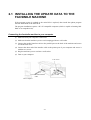
2.1 INSTALLING THE UPDATE DATA TO THE
FACSIMILE MACHINE
If the program version is updated or the main PCB is replaced, then install the update program
onto the flash ROM of the main PCB.
The program installation requires a PC/AT-compatible computer (which is capable of running MSDOS or its compatible OS).
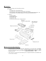
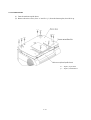
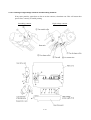
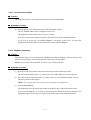
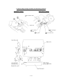
Connecting the facsimile machine to your computer
(1) Make sure that your computer is turned off.
(2) Make sure that the machine's power cord is unplugged from a wall socket.
(3) Connect the parallel interface cable to the parallel port on the back of the machine and secure
it with the lock wires.
(4) Connect the other end of the interface cable to the printer port of your computer and secure it
with the two screws.
(5) Plug the machine's power cord into a wall socket.
(6) Turn on your computer.
Lock wires
Parallel interface
cable
Host computer
2 -1
Installing the update data onto the flash ROM of the facsimile machine
NOTE: The following is an installation procedure example on a PC that is running Windows 95/98.
(1) Copy the update data and transfer utility onto the desired directory of the hard disk.
e.g., C:\UPDATE
(2) Click the Start button, point to Programs, and then click MS-DOS Prompt to open an MS-DOS
window.
(3) Type the drive letter where the update data and transfer utility are located. In the above
example, type C:\ from the command line and press the ENTER key.
Then type CD UPDATE and press the ENTER key.
(4) Check that your computer is connected with the facsimile machine correctly.
(5) To start the transfer utility transmitting the update data to the flash ROM of the facsimile
machine, type the following:
ICEN filename /b
Then press the ENTER key.
During downloading, the machine beeps intermittently.
Upon completion of the downloading, the machine beeps continuously.
NOTE: If the facsimile machine cannot return to the standby state after completion of downloading,
turn the power off and on.
2 -2
2.2 SETTING ID CODES TO FACSIMILE
MACHINES CONNECTED TO A SINGLE PC
VIA USB
Function
Brother facsimile machines are assigned ID codes (character strings) at the factory. If you replace
the main PCB of the machine, the machine will lose its assigned ID code so that it will not be
identified by the connected PC.
To connect those machines to a PC via USB, you need to assign ID codes (character strings) to
those individual machines according to the procedure given here. For models covered by this
manual, set serial numbers given to individual machines as ID codes.
Connecting each of facsimile machines to your PC
(1) Make sure that your PC is turned off.
(2) Make sure that the machine's power cord is unplugged from a wall socket.
(3) Connect the interface cable to the parallel interface port on the back of the facsimile machine
and secure it with the lock wires.
(4) Connect the other end of the interface cable to the printer port of your PC and secure it with
the two screws.
(5) Plug the machine's power cord into a wall socket.
(6) Turn on your PC.
Operating Procedure
(1) On your PC, run the ID setting utility. Follow the instructions shown on the PC's screen and
enter the 9-digit serial number (e.g., G01012345) printed on the nameplate attached to the
back of the facsimile machine as an ID code. Then press the Enter key.
The ID setting utility will transmit the ID code data from your PC to the facsimile machine
and then it will terminate.
The facsimile machine will automatically return to the standby mode.
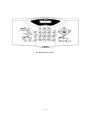
(2) To check whether the entered character string (ID code) is correct, make the machine enter the
maintenance mode (refer to Chapter 5, Section 5.1) and then press the 1 key twice.
The facsimile machine will print out a Configuration List. At the right top of the list, "SER.#:
BROXXXXXXXXX" is printed.
(3) Check that the character string entered in step (2) is printed in "XXXXXXXXX."
If it is OK, press the 9 key twice to exit from the maintenance mode.
If something other than that is printed in XXXXXXXXX, check the connection between the
PC and facsimile machine and go back to step (1).
2 -3
CHAPTER 3
THEORY OF OPERATION
CHAPTER 3 THEORY OF OPERATION
CONTENTS
3.1
OVERVIEW ......................................................................................................................3-1
3.2
MECHANISMS .................................................................................................................3-2
3.2.1
3.2.1.1
Document feeding and ejecting mechanism ................................................3-3
3.2.1.2
Scanner........................................................................................................3-3
3.2.2
Laser Printing Mechanism....................................................................................3-4
3.2.2.1
Paper pulling-in, registration, feeding, and ejecting mechanism..................3-4
3.2.2.2
Print process mechanism.............................................................................3-6
3.2.2.3
Heat-fixing mechanism ................................................................................3-7
3.2.3
3.3
Scanner Mechanism ............................................................................................3-3
Sensors and Actuators .........................................................................................3-8
CONTROL ELECTRONICS...........................................................................................3-10
3.3.1
Configuration ......................................................................................................3-10
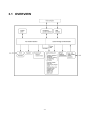
3.1 OVERVIEW
3 -1
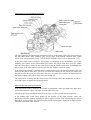
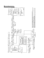
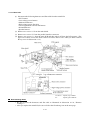
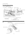
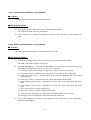
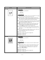
3.2 MECHANISMS
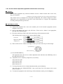
The facsimile machine is classified into the following mechanisms:
SCANNER MECHANISM
- Document feeding and ejecting mechanism
- Document scanning mechanism
LASER PRINTING MECHANISM
- Paper pulling-in, registration, feeding, and ejecting
mechanisms
- Print process mechanism (consisting of charging,
exposing, developing, transferring, and erasing
processes)
- Heat-fixing mechanism
SENSORS AND ACTUATORS
Document feeding and
ejecting mechanism
Document scanning
mechanism
SCANNER
MECHANISM
Paper ejecting mechanism
Paper pulling-in and
registration mechanism
Heat-fixing
mechanism
Print process
mechanism
LASER PRINTING MECHANISM
3 -2
With paper feeding
mechanism
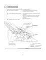
3.2.1 Scanner Mechanism
3.2.1.1
Document feeding and ejecting mechanism
This mechanism consists of the document stacker, automatic document feeder (ADF), document
ejection roller ASSY, and document sensors. (For details about the sensors, refer to Subsection
3.2.3.)
If you set documents on the document stacker with their faces down and start the scanning
operation, then the scanner motor rotates so that the ADF (which consists of the separation roller
and ADF parts) feeds those documents into the machine, starting from the bottom sheet (first page)
to the top (last page), page by page. Each document advances with the document feed roller ASSY
to the scanner, and then it is fed out of the machine with the document ejection roller ASSY.
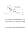
3.2.1.2
Scanner
The scanner uses a contact image sensor (CIS) unit which consists of an LED array illuminating
documents, a self-focus lens array collecting the reflected light, a CIS PCB carrying out
photoelectric conversion to output picture element data, and a cover glass on which a document
advances. When the document passes between the document pressure bar and the cover glass, it is
scanned.
3 -3
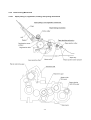
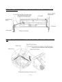
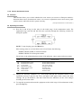
3.2.2 Laser Printing Mechanism
3.2.2.1
Paper pulling-in, registration, feeding, and ejecting mechanism
3 -4
Paper pulling-in and registration mechanism
The paper pulling-in and registration mechanism consists of the pull-in roller gear (incorporated in
the auto sheet feeder ASF), planetary gear system, paper feed solenoid, solenoid lever, clutch
release lever, and registration sensor. (For the details about the sensor, refer to Subsection 3.2.3.)
If the main motor rotates clockwise, the rotation is transmitted to the intermediate gear of the
planetary gear system. As the intermediate gear rotates, the pull-in roller drive gear also rotates
since the clutch gear is locked by the solenoid lever and the clutch release lever. Accordingly, the
pull-in roller in the ASF rotates to pull in paper into the machine, a sheet at a time.
If the paper feed solenoid is retracted and the clutch release lever is operated according to the cam
profile of the pull-in roller drive gear so as to release the clutch gear, the clutch gear rotates and
the pull-in roller drive gear does not rotate. This way, the clutch gear switches the transmission of
the motor rotation to the pull-in roller drive gear on and off.
The solenoid on/off timing and the clutch release lever timing allow this mechanism to pull in a
sheet and register it against the registration roller.
Paper feeding and ejecting mechanism
If the main motor rotates clockwise, the rotation is transmitted via the gear train to the drum drive
gear, heater roller drive gear, and paper ejection roller drive gear.
After the paper passes through the heat-fixing process, it will be ejected onto the paper tray.
If the leading edge of the paper pushes up the actuator of the paper ejection sensor, the
photosensor becomes opened, signaling the start of paper ejection. If the trailing edge has passed
through the sensor actuator, the sensor becomes closed, signaling the completion of paper ejection.
Then, the main motor stops rotation.
3 -5
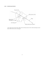
3.2.2.2
Print process mechanism
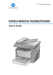
The print process unit works with laser beam, electrical charges, and toner. The graph below
shows the transition of electrical charge on the surface of the laser-sensitive drum through the five
processes: charging, exposing, developing, transferring, and erasing processes.
3 -6
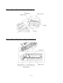
3.2.2.3
Heat-fixing mechanism
As the paper passes between the heater roller and the pressure roller in the heat-fixing unit, the
heater roller fuses the toner on the paper.
3 -7
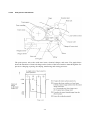
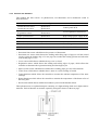
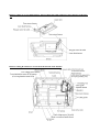
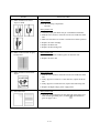
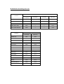
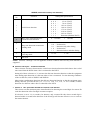
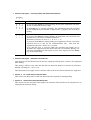
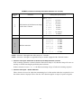
3.2.3 Sensors and Actuators
This machine has nine sensors: six photosensors, two thermistors and a mechanical switch as
described below.
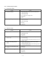
Sensor name
Type
Located on
Document front sensor
Document rear sensor
Photosensor
Photosensor
Control panel PCB
Cover sensor
Registration sensor
Photosensor
Photosensor
Cover/registration sensor PCB
Paper ejection sensor
Photosensor
High-voltage power supply PCB
Toner sensor
Photosensor
Toner sensor PCB
Toner thermistor
Thermistor
Toner sensor PCB
Heater thermistor
Thermistor
Heat-fixing unit
Hook switch
Mechanical switch
Hook switch PCB*
• Document front sensor which detects the presence of documents.
• Document rear sensor which detects the leading and trailing edges of pages to tell the control
circuitry when the leading edge of a new page has reached the starting position and when the
scan for that page is over.
• Cover sensor which detects whether the top cover is closed.
• Registration sensor which detects the leading and trailing edges of paper, which allows the
controller to determine the registration timing and check paper jam.
• Paper ejection sensor which detects whether the recording paper goes out of the machine.
• Toner sensor which detects whether there is toner or a toner cartridge is loaded.
• Toner thermistor which allows the controller to monitor the ambient temperature of the toner
cartridge.
• Heater thermistor which allows the controller to monitor the temperature of the heater roller of
the fixing unit.
• Hook switch which detects whether the handset is placed on the handset mount.
These photosensors are a photointerrupter consisting of a light-emitting diode and a light-sensitive
transistor. Each of them has an actuator separately arranged as shown on the next page.
3 -8
Location of Sensors and Actuators
3 -9
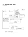
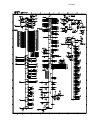
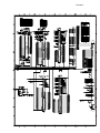
3.3 CONTROL ELECTRONICS
3.3.1 Configuration
The hardware configuration of the facsimile machine is shown below.
Configuration of Facsimile Machine
(NOTE 1) Not provided on some models.
(NOTE 2) Provided on the European, Pacific, and Asian versions.
3 -1 0
CHAPTER 4
DISASSEMBLY/REASSEMBLY AND
LUBRICATION
CHAPTER 4 DISASSEMBLY/REASSEMBLY AND LUBRICATION
CONTENTS
4.1
DISASSEMBLY/REASSEMBLY......................................................................................4-1
Safety Precautions .......................................................................................................4-1
Tightening Torque List......................................................................................................4-2
Preparation ..................................................................................................................4-3
How to Access the Object Component ........................................................................4-3
Disassembly Order Flow..............................................................................................4-4
4.1.1
Document Guide Base .........................................................................................4-5
4.1.2
Board Access Cover.............................................................................................4-5
4.1.3
Auto Sheet Feeder (ASF).....................................................................................4-6
4.1.4
Handset Mount and Control Panel ASSY...........................................................4-12
4.1.5
Panel Rear Cover and Control Panel .................................................................4-14
4.1.6
Top Cover...........................................................................................................4-17
4.1.7
CIS Unit ..............................................................................................................4-19
4.1.8
Hook Switch PCB ...............................................................................................4-20
4.1.9
Document Feed Roller ASSY, Scanner Drive Unit, and Document Ejection
Roller ASSY........................................................................................................4-21
4.1.10 Separation Roller and its Gear ...........................................................................4-23
4.1.11 Heat-fixing Unit, FU Lamp, and Paper Ejection Sensor Actuator.......................4-25
4.1.12 Laser Unit and Toner Sensor PCB.....................................................................4-27
4.1.13 Main PCB ...........................................................................................................4-28
4.1.14 Bottom Plate.......................................................................................................4-30
4.1.15 Low-voltage Power Supply PCB.........................................................................4-31
4.1.16 High-voltage Power Supply PCB........................................................................4-32
4.1.17 Duct and Fan......................................................................................................4-33
4.1.18 Top Cover Sensor Actuator................................................................................4-34
4.1.19 Power Supply Shield ..........................................................................................4-34
4.1.20 Speaker ..............................................................................................................4-35
4.1.21 Gear Drive Unit...................................................................................................4-36
4.1.22 PCB Support and NCU PCB ..............................................................................4-38
4.1.23 Side Covers R and L ..........................................................................................4-39
4.1.24 Scanner Grounding Plate ...................................................................................4-40
4.1.25 EL (Eraser Lamp) Board ....................................................................................4-41
4.1.26 Harness Routing.................................................................................................4-42
4.1.27 Cleaning of High-voltage Contacts and Grounding Contacts.............................4-46
4.2 LUBRICATION ..................................................................................................................4-47
4.1 DISASSEMBLY/REASSEMBLY
Safety Precautions
To prevent the creation of secondary problems by mishandling, observe the following precautions
during maintenance work.
(1) Unplug the power cord from the power outlet before replacing parts or units. When having
access to the power supply, be sure to unplug the power cord from the power outlet.
(2) When servicing the optical system of the laser printing unit, be careful not to place
screwdrivers or other reflective objects in the path of the laser beam. Be sure to take off any
personal accessories such as wrist watches and rings before working on the printer. A
reflected beam, though invisible, can permanently damage your eyes.
(3) If the machine has been printing, allow the heat-fixing unit sufficient time to cool down before
starting maintenance jobs. It is HOT!
(4) Be careful not to lose screws, washers, or other parts removed for parts replacement.
(5) Do not remove gears from the document feed roller ASSY or ejection roller ASSY if at all
possible. Once removed, they will become unusable and new gears will have to be put back in.
(6) When using soldering irons and other heat-generating tools, take care not to damage the resin
parts such as wires, PCBs, and covers.
(7) Before handling the PCBs, touch a metal portion of the machine to discharge static electricity;
otherwise, the electronic parts may be damaged due to the electricity charged in your body.
(8) When transporting PCBs, be sure to wrap them in conductive sheets such as aluminum foil.
(9) Be sure to reinsert self-tapping screws correctly, if removed.
(10) Tighten screws to the torque values listed on the next page.
(11) When connecting or disconnecting cable connectors, hold the connector bodies not the cables.
If the connector has a lock, always slide the connector lock to unlock it.
(12) Before reassembly, apply the specified lubricant to the specified points. (Refer to Subsection
4.2 in this chapter.)
(13) After repairs, check not only the repaired portion but also that the connectors and other related
portions function properly before operation checks.
4 -1
Tightening Torque List
Location
Screw type
Q'ty
Tightening torque
N•m (kgf•cm)
Board access cover
Taptite, bind B M4x12
2
0.98 ±0.20
(10 ±2)
Release lever
Taptite, bind B M4x10
1
0.69 ±0.20
(7 ±2)
Grounding leaf spring R
Taptite, bind B M2.6x8
1
0.39 ±0.10
(4 ±1)
Grounding leaf spring L
Taptite, bind B M2.6x8
2
0.39 ±0.10
(4 ±1)
ADF parts
Taptite, pan B M3x6
1
0.49 ±0.20
(5 ±2)
Panel rear cover
Taptite, cup B M3x8
2
0.49 ±0.20
(5 ±2)
Link stoppers
Taptite, pan B M4x6D 10
2
0.49 ±0.20
(5 ±2)
FG wire & main PCB
Taptite, cup S M3x6
1
0.69 ±0.20
(7 ±2)
CIS shield plate
Taptite, cup B M3x6
3
0.49 ±0.20
(5 ±2)
Scanner drive unit
Taptite, cup B M3x8
2
0.49 ±0.20
(5 ±2)
Scanner motor
Screw, pan (washer) M3x6DA
1
0.69 ±0.20
(7 ±2)
Heat-fixing unit
Taptite, cup B M4x16
2
0.98 ±0.20
(10 ±2)
Fixing unit upper cover
Taptite, bind B M3x12
2
0.69 ±0.20
(7 ±2)
Lock plate
Taptite, pan B M3x10
1
0.69 ±0.20
(7 ±2)
Fuse plate R
Screw, pan (washer) M2.6x6DA
1
0.39 ±0.10
(4 ±1)
Laser unit
Taptite, bind B M4x12
3
0.98 ±0.20
(10 ±2)
Main shield
Taptite, cup S M3x6
2
0.69 ±0.20
(7 ±2)
Parallel interface connector
Taptite, pan S M3x12
2
0.69 ±0.20
(7 ±2)
Main PCB
Taptite, cup S M3x6
1
0.69 ±0.20
(7 ±2)
Bottom plate
Taptite, bind B M4x12
5
0.98 ±0.20
(10 ±2)
Taptite, cup S M3x6
4
0.69 ±0.20
(7 ±2)
Low-voltage power supply PCB Taptite, cup S M3x6
(Low-voltage insulator sheet)
2
0.69 ±0.20
(7 ±2)
Grounding wire
Screw, pan (washer) M4x8DB
1
0.39 ±0.20
(4 ±2)
Power inlet support
Taptite, cup S M3x6
1
0.69 ±0.20
(7 ±2)
High-voltage power supply PCB Taptite, bind B M4x12
1
0.98 ±0.20
(10 ±2)
Duct
Taptite, bind B M4x12
2
0.98 ±0.20
(10 ±2)
Fan support
Taptite, cup B M3x8
1
0.49 ±0.20
(5 ±2)
Power supply shield
Taptite, cup S M3x6
2
0.69 ±0.20
(7 ±2)
Gear drive unit
Taptite, bind B M4x14
4
0.98 ±0.20
(10 ±2)
Main motor
Taptite, cup S M3x6
2
0.69 ±0.20
(7 ±2)
Motor support plate
Taptite, cup S M3x16
2
0.69 ±0.20
(7 ±2)
PCB support
Taptite, bind B M4x12
2
0.98 ±0.20
(10 ±2)
NCU shield
Taptite, cup S M3x6
2
0.69 ±0.20
(7 ±2)
NCU PCB
Taptite, cup S M3x6
1
0.69 ±0.20
(7 ±2)
Scanner grounding plate
Taptite, cup B M3x8
1
0.49 ±0.20
(5 ±2)
Side covers R and L
Taptite, bind B M4x12
4
0.98 ±0.20
(10 ±2)
4 -2
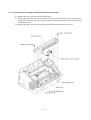
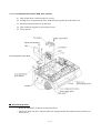
Preparation
Prior to proceeding to the disassembly procedure,
(1) Unplug
- the modular jack of the telephone line,
- the modular jack of the curled cord (and remove the handset),
- the PC interface cable (parallel cable or USB cable) if connected (Not shown below), and
- the modular jack of an external telephone set if connected (Not shown below).
(2) Remove
- the paper support,
- the document support,
- the document tray,
- the paper tray, and
- the drum unit (with the toner cartridge loaded)
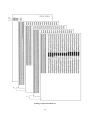
How to Access the Object Component
• On the next page is a disassembly order flow which helps you access the object components.
To remove the gear drive unit, for example, first find it on the flow and learn its number ( in
so as to access
this case). You need to remove parts numbered , , , , , , , and
the gear drive unit.
• Unless otherwise specified, the disassembled parts or components should be reassembled in the
reverse order of removal.
4 -3
Disassembly Order Flow
4 -4
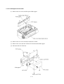
4.1.1 Document Guide Base
(1) Lift up the document guide base.
4.1.2 Board Access Cover
(1) Remove two screws.
(2) Push down the top of the board access cover to release the two latches from the main cover,
then pull it to the rear.
4 -5
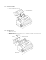
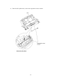
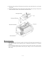
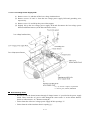
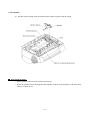
4.1.3 Auto Sheet Feeder (ASF)
(1) If the board access cover has not been removed in Subsection 4.1.2, you need to remove the
two screws with which the board access cover and ASF are fastened together to the main
cover.
(2) Open the top cover.
(3) Pull the ASF to the front and then lift it up.
4 -6
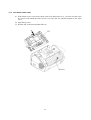
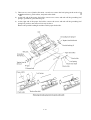
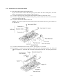
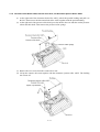
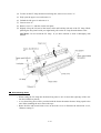
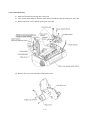
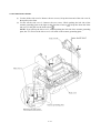
[Disassembling the ASF]
1) Unhook the release lever spring.
2) Remove screw "a" and pull out the release lever.
3) Turn the release cam to the front and pull it out to the left.
4 -7
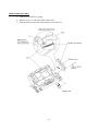
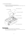
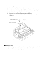
4) At the right end of the ASF, remove the screw from the grounding leaf spring R. (It is not
necessary to remove the leaf spring.) Next pull out the pawled bushing R.
At the left end of the ASF, remove the sector gear and its spring. Unlatch the pawled bushing
L to the left and then remove it from the paper pull-in roller shaft. Remove the paper pull-in
roller.
5) Push the right and left ends of the separation pad ASSY inwards and take it out. The spring
also comes off.
4 -8
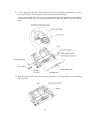
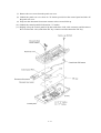
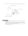
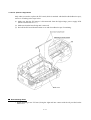
6) Turn the ASF upside down, remove the registration sensor actuator.
4 -9
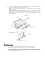
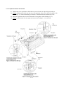
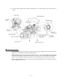
7) There are two sets of pinch roller units. At each set, remove the leaf spring (in the order of
to shown below), pinch rollers, and pinch roller shaft.
8) At the left end of the paper feed roller, remove two screws and take off the grounding leaf
spring L, pawled PF gear, and idle gear.
9) At the right end of the paper feed roller, remove the screw and take off the grounding leaf
spring R if you have not removed it in step 4) above.
Remove the pawled bushing R and take out the paper feed roller.
4 -1 0
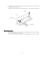
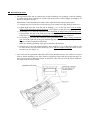
10) Press the lock arm provided at the left inside of the ASF to the rear with a screwdriver, slide
the ASF chute ASSY to the left, and take it out to the front.
NOTE: To replace only the black film attached to the chute, do not remove the ASF chute
ASSY from the ASF.
NOTE: A new chute and black film will be provided separately. When replacing the chute
ASSY, first set the chute into the ASF and then attach the black film to the chute. If you first
attach the black film to the chute and then set the ASF chute ASSY, then the black film may
be bent or wrinkled.
Reassembling Notes
• Set the paper feed roller into the ASF with the D-shaped end facing leftwards.
• Set the paper pull-in roller into the ASF with the D-shaped end facing leftwards.
• When setting the release lever back into place, turn the release cam to the rear and then set the
release lever so that the bottom end of the release lever comes in the front of the boss provided
on the ASF as illustrated on page 4-7.
4 -1 1
4.1.4 Handset Mount and Control Panel ASSY
(1) Open the control panel ASSY.
(2) Open the top cover.
(3) Unhook the three latches of the handset mount from the top cover and remove it.
4 -1 2
(4) Disconnect the panel-hook SW harness from the hook sensor PCB and take it out from the
cable guides.
(5) Push the right-hand arm of the control panel ASSY inwards with your finger and open the
control panel ASSY further. Then lift up the control panel ASSY.
Reassembling Notes
• Route the panel-hook SW harness together with the hook SW-main harness through the two
cable guides provided on the scanner drive unit, as illustrated in Subsection 4.1.26, "Harness
routing B."
• When installing the handset mount, first fit the two tabs provided at the upper section into the
top cover and then snap the handset mount into place, taking care not to let it hold down the
hook switch.
4 -1 3
4.1.5 Panel Rear Cover and Control Panel
(1) Place the control panel ASSY upside down.
If you do not need to remove the ADF parts, pinch rollers and their related parts, anti-static
brush, or document rear sensor actuator, skip to step (6).
(2) To remove the ADF parts (spring plates and separation rubber), remove the screw.
(3) To remove the pinch rollers and their related parts, press the lock arm to the rear and shift the
pinch roller shaft to the left.
(4) To replace the anti-static brush, remove it.
NOTE: Once removed, the anti-static brush will become unusable and a new part will have to
be put back in.
(5) To remove the document rear sensor actuator, pull support "c" outwards.
(6) Pull support "a" to the front to release the center tab of the document pressure bar. Next pull
either of supports "b" outwards and lift up the document pressure bar. The spring also comes
off.
4 -1 4
(7) Remove the two screws from the panel rear cover.
(8) Unhook the panel rear cover from 10 "X" latches provided on the control panel and take off
the panel rear cover.
(9) Fully turn the document front sensor actuator to the rear and lift it up.
(10) Unhook the control panel PCB from four "Y" latches.
(11) Slightly lift up the control panel PCB, then unlock the LCD cable connector and disconnect
the LCD flat cable. Next, unlock the FPC key connector and disconnect the FPC key.
4 -1 5
(12) As shown below, pull the clamp outwards to release the LCD and take out the LCD while
pulling the LCD flat cable gently.
NOTE: Do not take out the LCD except when the LCD is defective and requires replacement.
Reassembling Notes
• Before reinstalling the LCD to the control panel, wipe fingerprints or dust off the LCD surface
and control panel window with a soft cloth.
• A new LCD is covered with a protection sheet. Before installing it, remove the protection sheet.
4 -1 6
4.1.6 Top Cover
(1) Remove the board access cover if installed.
(2) Disconnect the CIS harness, hook SW-main harness, and scanner motor harness from the main
PCB.
(3) Remove the screw that secures the FG wire to the PCB support.
(4) Release the hook SW-main harness, scanner motor harness, and FG wire from the two cable
guides provided on the main cover. (See Subsection 4.1.26, "Harness routing D.")
(5) Open the top cover.
(6) At each of the right and left sides of the top cover, remove the screw from the link stopper.
Then pull the link stopper outwards and open the top cover further.
(7) Turn the top cover upright and then lift it up to the rear.
(8) Turn each link stopper to the rear and pull it out inwards.
4 -1 7
Reassembling Notes
• Before reinstalling the top cover, route the FG wire, hook SW-main harness, scanner motor
harness, and CIS harness on the underside of the top cover as illustrated in Subsection 4.1.26,
”Harness routing C."
After installing the top cover, route the FG wire and those three harnesses on the main cover as
illustrated in Subsection 4.1.26, "Harness routing D and E."
• When routing the FG wire, hook SW-main harness, and scanner motor harness through the
cable guides, be sure to first route the FG wire and then route those two harnesses. This may
prevent the FG wire from working out of the cable guides.
• When disposing of top covers, remove two leaf springs from each top cover with a flat
screwdriver to separate metallic springs from plastic covers.
4 -1 8
4.1.7 CIS Unit
(1) Turn the top cover upside down.
(2) Remove the three screws from the CIS shield plate. The FG wire and feed roller grounding
spring also come off.
(3) Disconnect the CIS harness from the CIS unit.
(4) Turn the top cover rightside up.
(5) Slightly pull up the lock arm, move the CIS unit to the left, and lift up the right edge of the
CIS unit.
(6) Remove the two CIS springs.
Reassembling Notes
• When reinstalling the CIS unit, first insert the left end under the lock arm, put the CIS unit into
the top cover, and move it to the right. After installation, wipe fingerprints or dust off the CIS
surface with a soft cloth.
• When reinstalling the CIS shield plate, secure it to the top cover together with the feed roller
grounding spring and FG wire. The FG wire should be routed as illustrated in Subsection
4.1.26, "Harness routing C."
• Route the CIS harness on the underside of the top cover as illustrated in Subsection 4.1.26,
"Harness routing C."
4 -1 9
4.1.8 Hook Switch PCB
(1) From the top cover, unhook the hook switch PCB and take it out.
(2) Take out the hook SW-main harness from the cable guides provided on the scanner drive unit.
Reassembling Notes
• Route the hook SW-main harness through the cable guides provided on the scanner drive unit
as illustrated in Subsection 4.1.26, "Harness routing B."
4 -2 0
4.1.9 Document Feed Roller ASSY, Scanner Drive Unit, and Document Ejection Roller ASSY
(1) At the right end of the document feed roller ASSY, unlock the pawled bushing and pull it to
the left. Then remove the document feed roller ASSY together with the pawled bushing.
(2) At the right end of the pressure roller shaft, press the latch to the rear and take out the pressure
rollers and their shaft. Then remove the pressure roller springs.
(3) Remove the two screws from the scanner drive unit.
(4) Lift up the scanner drive unit together with the document ejection roller ASSY. The bushing
also comes off.
4 -2 1
(5) Remove the screw from the scanner motor and take off the motor from the scanner drive unit.
Reassembling Notes
• When securing the scanner motor to the scanner drive unit, face the motor connector up as
shown above.
• Before putting the scanner drive unit into the top cover, make sure that the stopper of bushing L
("a" in Figure A given on the next page) faces up when viewed from the top. Then move
bushing L to the right to fit it in the cutout provided in the top cover.
• Before securing the scanner drive unit to the top cover with two screws, set the document
ejection roller ASSY into place.
4 -2 2
4.1.10 Separation Roller and its Gear
(1) Turn the top cover upside down. Place the top cover with its rear edge facing towards you.
(2) Slightly push down the lock arm and move the separation roller gear to the left together with
its bushing L ("a" in the illustration given below). Then take them out from the top cover.
(3) Move the separation roller to the left and take it out together with its bushing S ("b").
(4) Slightly push down the lock arm again and remove the bushing L ("c") to the left.
4 -2 3
Reassembling Notes
• The separation roller and its related parts use three bushings (two bushings L and one bushing
S). When fitting those bushings, be careful with the direction of their flanges and stoppers as
shown on the previous page.
What follows is the installation procedure of the separation roller and its related parts.
1) Turn the top cover upside down. Place the top cover with its rear edge facing towards you.
2) Lightly push down the lock arm and fit bushing L ("c") to the top cover with its flange
facing to left and with its stopper facing up. (See Figure C on the previous page.)
3) Set bushing S ("b") onto the separation roller shaft with its flange facing towards the roller.
First insert the left end of the roller shaft into bushing L ("c") and then insert the right end
to the top cover with the stopper of bushing S ("b") facing down. (See Figure B.)
4) Set bushing L ("a") onto the separation roller gear shaft with its flange facing towards the
gear. Insert the right end of the gear shaft through the cutout provided in the top cover and
engage it with the separation roller shaft.
Make sure that the separation roller gear is locked by the lock arm.
5) Turn the top cover to the normal position. Move bushing L ("a") to the right so that it will
be fitted to the cutout provided in the top cover with its stopper facing up when viewed
from the top. (See Figure A.)
• Once removed, the separation roller film will become unusable and new one will have to be put
back in. When attaching a new film, align its left and top edges with the left and top edges of
the recessed section as illustrated below. In particular, take care not to let the film override the
rear edge of the recessed section.
4 -2 4
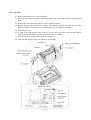
4.1.11 Heat-fixing Unit, FU Lamp, and Paper Ejection Sensor Actuator
(1) Remove the two screws from the heat-fixing unit.
(2) Lift up the heat-fixing unit and disconnect the blue and brown heater wires (of the heater
harness) from the heat-fixing unit. Then disconnect the heater thermistor harness from the EL
(eraser lamp) board.
(3) Remove the paper ejection sensor actuator from the bottom of the heat-fixing unit.
4 -2 5
(4) To take out the FU lamp from the heat-fixing unit, remove two screws "a."
(5) Fully open the upper cover and remove it.
(6) Unlatch the idle gear 16 and remove it.
(7) Loosen screw "b."
(8) Remove screw "c" and take out the lock plate.
(9) Slightly lift up the left end of the heater roller and hold the left end of the FU lamp. While
pinching the fuse plate R with your right hand, pull out the FU lamp from the heater roller.
CAUTION: Do not touch the FU lamp. If you have touched it, clean it thoroughly with
alcohol.
Reassembling Notes
• When setting the FU lamp into the heat-fixing unit, be sure to insert the right edge of the wire
into the folded fuse plate R.
• A new heat-fixing unit will be provided with the heater thermistor harness being taped to the
unit. When installing the unit, remove the tape.
• Route the blue and brown heater wires on the main cover as illustrated in Subsection 4.1.26,
"Harness routing F."
4 -2 6
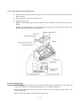
4.1.12 Laser Unit and Toner Sensor PCB
(1) Disconnect the polygon motor flat cable, toner sensor harness, and laser diode harness from
the main PCB.
(2) Remove the three screws from the laser unit.
(3) Lift up the laser unit.
NOTE: When handling the laser unit, take care not to touch the inside of the unit, glass, or
mirror.
NOTE: On the small PCB at the right side of the laser unit is a 2-pin connector which is for
the adjustment in the factory. Do not disturb it.
n Reassembling Notes
• On the underside of the laser unit, route the laser diode harness, polygon motor flat cable, and
toner sensor harness as illustrated in Subsection 4.1.26, "Harness routing G."
• Before putting the laser unit back into place, check for any toner particles, paper dust or dirt,
and clean them out.
• Make sure that the sponge is placed below the laser unit.
4 -27
4.1.13 Main PCB
(1) Disconnect the following harnesses and flat cable from the main PCB:
• NCU harness
• Low-voltage power harness
• Main motor harness
• High-voltage power flat cable
• Cover/registration sensor & fan harness
• Solenoid harness
• Speaker harness
(2) Remove two screws "a" from the main shield.
(3) Remove two screws "b" from the parallel interface connector.
(4) Remove two screws "c" from the main PCB and then take it off from the PCB support. (The
upper one of these screws has been removed to release the FG wire when you have removed
the top cover in Subsection 4.1.6.)
"a" and "c": Taptite, cup S M3x6
"b":
Taptite, pan S M3x12
Reassembling Notes
• Be sure to route the harnesses and flat cable as illustrated in Subsection 4.1.26, "Harness
routing A."
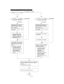
• After you replace the main PCB, be sure to follow the flowchart given on the next page.
4 -2 8
Setting up the main PCB after replacement
4 -2 9
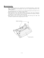
4.1.14 Bottom Plate
(1) Turn the machine upside down.
(2) Remove the nine screws (four "x" and five "y") from the bottom plate, then lift it up.
"x": Taptite, cup S M3x6
"y": Taptite, bind B M4x12
4 -3 0
4.1.15 Low-voltage Power Supply PCB
(1) Remove screw "a" and take off the low-voltage insulator sheet.
(2) Remove screws "b" and "c" from the low-voltage power supply PCB and grounding wire,
respectively.
(3) Remove screw "d" and lift up the power inlet support.
(4) Slightly lift up the low-voltage power supply PCB and disconnect the low-voltage power
harness and heater harness (of the blue and brown wires).
"a," "b," and "d": Taptite, cup S M3x6
"c": Screw, pan (washer) M4x8DB
Reassembling Notes
• Be sure to route the heater harness through U-shaped cutout "e" provided in the power supply
shield. Then, route the AC power cable through the same cutout "e" on the heater harness.
(Refer to Subsection 4.1.26, "Harness routing H."
• Fit the front tabs of the low-voltage power supply PCB in openings "f."
• Fit the front tab of the insulator sheet in opening "g."
4 -3 1
4.1.16 High-voltage Power Supply PCB
(1) Remove the screw and take off the high-voltage insulator sheet.
(2) Slightly lift up the high-voltage power supply PCB and disconnect the high-voltage power flat
cable and EL (eraser lamp) harness.
Reassembling Notes
• Fold the high-voltage power flat cable and route it as illustrated above.
• Before reinstalling the high-voltage power supply PCB, check the high-voltage contacts for any
toner particles, paper dust or dirt, and clean them out.
4 -3 2
4.1.17 Cover/Registration Sensor PCB, Duct, and Fan
(1) Take off the duct by removing the two screws.
(2) Unlatch the cover/registration sensor PCB and lift it up and out of the main cover.
(3) Disconnect the fan harness from the PCB.
(4) Take off the fan support by removing the screw.
(5) Lift up the fan.
Reassembling Notes
• Route the fan harness on the fan as illustrated above.
• Put the fan back into place with the label side facing outwards and with its harness directed as
shown above.
4 -3 3
4.1.18 Top Cover Sensor Actuator
(1) Pull up the top cover sensor actuator.
4.1.19 Power Supply Shield
(1) Remove the two screws and lift up the power supply shield.
Reassembling Notes
• When reinstalling the power supply shield, route the low-voltage power harness through the
opening and route the heater harness through U-shaped cutout "e" as shown above.
4 -3 4
4.1.20 Speaker
(1) Pull the speaker spring inwards and pull up the speaker together with the spring.
Reassembling Notes
• Put the speaker into place with its harness facing up.
• Route the speaker harness through the latch together with the solenoid harness and main motor
harness as shown above.
4 -3 5
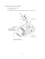
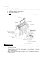
4.1.21 Gear Drive Unit
(1) Make sure that the heat-fixing unit is removed.
(2) Take out the heater harness from the cable guides provided on the top of the gear drive unit.
(3) Remove the four screws and lift up the gear drive unit.
(4) Remove the two screws and take off the main motor.
4 -3 6
(5) To take off the paper feed solenoid, solenoid lever, or clutch release lever, remove the two
screws.
Reassembling Notes
• If the friction spring in the gear drive unit slips off, fit the straight end of the spring in the
support hole of the gear drive unit as illustrated above.
• When putting the gear drive unit back into the main cover, route the solenoid harness and main
motor harness along the outside of the gear drive unit. Be sure to sandwich the grounding plate
between the contact plate and gear drive unit. See the illustration given on the previous page.
• After securing the gear drive unit, route the heater harness through the cable guides provided on
the top of the gear drive unit.
4 -3 7
4.1.22 PCB Support and NCU PCB
(1) Remove the two screws and lift up the PCB support.
(2) Remove the two screws and take off the NCU shield.
(3) Remove the screw and take off the NCU PCB from the PCB support.
(4) Disconnect the NCU harness.
4 -3 8
4.1.23 Side Covers R and L
(1) To take off the side cover R: Remove the two screws, lift up the front end of the side cover R,
then pull it to the front.
(2) To take off the side cover L: Remove the two screws. While pushing the left side of the
scanner grounding plate to the right (in the direction of arrow ), lift up the front end of the
side cover L and pull it to the front (arrow ).
NOTE: If you pull up the side cover L without pushing the left side of the scanner grounding
plate, the "X" section of the side cover L will catch on the scanner grounding plate.
4 -3 9
4.1.24 Scanner Grounding Plate
(1) Make sure that the heat-fixing unit is removed.
(2) Remove the screw from the scanner grounding plate. (If the bottom plate has not been
removed, remove screw "y" also (see page 4-30) that secures both the scanner grounding plate
and bottom plate.)
(3) Slightly lift up the scanner grounding plate and unhook the spring.
(4) You may peel off the anti-static brush from the scanner grounding plate.
NOTE: Once removed, the anti-static brush will become unusable and a new one will have to
be put back in.
Reassembling Notes
• Before attaching a new anti-static brush onto the scanner grounding plate, wipe the surface of
the attaching place with a cloth dampened with alcohol.
• When reinstalling the scanner grounding plate, fit it over the two bosses of the main cover.
4 -4 0
4.1.25 EL (Eraser Lamp) Board
Only when you need to replace the EL board (which is attached with double-sided adhesive tape),
remove it according to the steps below.
(1) Make sure that the EL harness is disconnected from the high-voltage power supply PCB.
(Refer to Subsection 4.1.16.)
(2) Make sure that the heat-fixing unit is removed.
(3) Peel off the EL board from the main cover and clear adhesive tape if remaining.
Reassembling Notes
• When attaching a new EL board, bring the right end into contact with the rib provided on the
main cover.
4 -4 1
4.1.26 Harness Routing
Harness routing A: Main PCB-related harnesses
Harness routing B: Panel-hook SW harness, hook SW-main harness, and scanner motor harness on the
main cover
4 -4 2
Harness routing C: Hook SW-main harness, scanner motor harness, FG wire, and CIS harness on the
underside of the top cover
Harness routing D: Hook SW-main harness, scanner motor harness, and FG wire on the top of the main
cover
4 -4 3
Harness routing E: CIS harness on the top of the main cover
Harness routing F: Heater harness on the top of the main cover
4 -4 4
Harness routing G: Laser diode harness, polygon motor flat cable, and toner sensor harness on the laser
unit
Harness routing H: Harnesses viewed from the bottom of the machine
4 -4 5
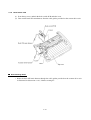
4.1.27 Cleaning of High-voltage Contacts and Grounding Contacts
If any toner particles, paper dust or dirt are on the contacts, clean them out. This will ensure that
power flows correctly to enable printing.
Grounding contacts
High-voltage contacts
4 -4 6
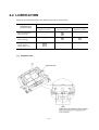
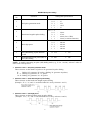
4.2 LUBRICATION
Apply the specified lubricants to the lubrication points as shown below.
Lubricant type
(Manufacturer)
Lubricant amount
Half of rice-sized pinch
of grease (3 mm3)
Molykote EM-D110
(Dow Corning)
–––––––
Molykote grease PG-662
(Dow Corning)
–––––––
Conductive grease
FLOIL GE676
(Kanto Kasei Ltd.)
[1]
Rice-sized pinch
of grease (6 mm3)
–––––––
–––––––
Separation pad
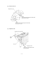
4 -4 7
Two rice-sized pinches
of grease (12 mm3)
–––––––
[2]
Scanner drive unit
[3]
Separation roller
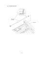
4 -4 8
[4]
Document feed roller
4 -4 9
CHAPTER 5
MAINTENANCE MODE
CHAPTER 5 MAINTENANCE MODE
CONTENTS
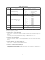
5.1
ENTRY INTO THE MAINTENANCE MODE ....................................................................5-1
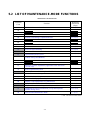
5.2
LIST OF MAINTENANCE-MODE FUNCTIONS ..............................................................5-2
5.3
DETAILED DESCRIPTION OF MAINTENANCE-MODE FUNCTIONS ..........................5-4
5.3.1
EEPROM Parameter Initialization ........................................................................5-4
5.3.2
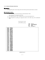
Printout of Scanning Compensation Data ............................................................5-5
5.3.3
ADF Performance Test ........................................................................................5-7
5.3.4
Test Pattern 1.......................................................................................................5-8
5.3.5
Firmware Switch Setting and Printout ..................................................................5-9
5.3.6
Operational Check of LCD .................................................................................5-12
5.3.7
Operational Check of Control Panel PCB ..........................................................5-12
5.3.8
Receiver Volume Adjustment (applicable to the American version only)...........5-14
5.3.9
Sensor Operational Check .................................................................................5-15
5.3.10 Fine Adjustment of Scanning Start/End Position ...............................................5-16
5.3.11 CIS Scanner Area Setting ..................................................................................5-17
5.3.12 EEPROM Customizing .......................................................................................5-17
5.3.13 Printout of the Equipment's Log Information ......................................................5-18
5.3.14 Display of the Equipment's Log Information.......................................................5-18
5.3.15 Equipment Error Code Indication .......................................................................5-19
5.3.16 Output of Transmission Log to the Telephone Line ...........................................5-19
5.3.17 Cancellation of the Memory Security Mode (applicable to the European
version only) .......................................................................................................5-20
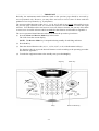
5.1 ENTRY INTO THE MAINTENANCE MODE
To make the equipment enter the maintenance mode, press the Menu, *, 2, 8, 6, and 4 keys in this
order.
Within 2 seconds
" on the
The equipment beeps for approx. one second and displays "
LCD, indicating that it is placed in the initial stage of the maintenance mode, a mode in which the
equipment is ready to accept entry from the keys.
To select one of the maintenance-mode functions listed in Section 5.2, enter the corresponding 2digit function code with the numerical keys on the control panel. (The details of each maintenancemode function are described in Section 5.3.)
NOTES: • Pressing the 9 key twice in the initial stage of the maintenance mode makes the equipment
exit from the maintenance mode, restoring it to the standby state.
• Pressing the Stop key after entering only one digit restores the equipment to the initial
stage of the maintenance mode.
• If an invalid function code is entered, the equipment resumes the initial stage of the
maintenance mode.
5 -1
5.2 LIST OF MAINTENANCE-MODE FUNCTIONS
Maintenance-mode Functions
EEPROM Parameter Initialization
Reference
Subsection
(Page)
5.3.1 (5-4)
Printout of Scanning Compensation Data
5.3.2 (5-5)
08
ADF* Performance Test
5.3.3 (5-7)
09
Test Pattern 1
5.3.4 (5-8)
10
Firmware Switch Setting
5.3.5 (5-9)
11
Printout of Firmware Switch Data
5.3.5 (5-11)
12
Operational Check of LCD
5.3.6 (5-12)
13
Operational Check of Control Panel PCB
(Check of Keys and Buttons)
5.3.7 (5-12)
16
Receiver Volume Adjustment (applicable to the American
version only)
5.3.8 (5-14)
32
Sensor Operational Check
5.3.9 (5-15)
54
Fine Adjustment of Scanning Start/End Position
5.3.10 (5-16)
55
CIS Scanner Area Setting
5.3.11 (5-17)
74
EEPROM Customizing
5.3.12 (5-17)
77
Printout of the Equipment's Log Information
5.3.13 (5-18)
80
Display of the Equipment's Log Information
5.3.14 (5-18)
82
Equipment Error Code Indication
5.3.15 (5-19)
87
Output of Transmission Log to the Telephone Line
5.3.16 (5-19)
91
EEPROM Parameter Initialization (except the telephone
number storage area)
5.3.1 (5-4)
99
Exit from the Maintenance Mode
----- (5-1)
Function
Code
01
Function
02
03
04
05
06
07
14
15
* ADF: Automatic document feeder
5 -2
- - - - - - - - - - - - - - - - - - - - - - - - - - IMPORTANT - - - - - - - - - - - - - - - - - - - - - - - - - - - - - - Basically, the maintenance-mode functions listed on the previous page should be accessed by
service personnel only. However, you may allow end users to access some of these under the
guidance of service personnel (e.g., by telephone).
The user-accessible functions (codes 10, 11, 12, 54, 82, 87 and 91) are shaded in the table given on
the previous page. Function code 10 accesses the firmware switches, each of which has eight
selectors. You should not allow end users to access all of those selectors, but you may allow them
to access user-accessible selectors which are shaded in the firmware switch tables in Appendix 2.
The service personnel should instruct end users to follow the procedure given below.
(1) Press the Menu and Receive Mode keys in this order.
The LCD clears the current display.
NOTE: The Receive Mode key is inoperable during standby for redialing and timer.
(2) Press the 0 key.
(3) Enter the desired function code (10, 11, 12, 54, 82, 87, or 91) with the numerical keys.
For function code 10, access the desired firmware switch according to the operating procedure
described in Appendix 2.
(4) To make the equipment return to the standby state, press the Stop key.
Stop key
0 key
5 -3
Menu key
Receive Mode key
5.3 DETAILED DESCRIPTION OF
MAINTENANCE-MODE FUNCTIONS
5.3.1 EEPROM Parameter Initialization
Function
The equipment initializes the parameters, user switches, and firmware switches registered in the
EEPROM, to the initial values. Entering the function code 01 initializes all of the EEPROM areas,
but entering 91 does not initialize some areas, as listed below.
Function code
01
Data item
Maintenance-mode functions
User switches
Firmware switches
Remote activation code
These will be
initialized
Activity report
Station ID data
Outside line number
Telephone function registration
One-touch dialing
Speed dialing
Group dialing
Received FAX messages
temporarily stored in the flash
memory (Not applicable to the
American version)
EEPROM customizing code
(4-digit)
91
All of these will be.
initialized
These will not be
initialized
These will not be initialized.
(Note that the first digit of the 4-digit customizing
code will be initialized to "0." If the code is 1001, for
example, it will be initialized to 0001.)
NOTE: If you replace the main PCB with one used for other facsimile equipment, carry out this
procedure and then customize the EEPROM (maintenance-mode function code 74 in Subsection
5.3.12).
Operating Procedure
(1) Press the 0 and 1 keys (or the 9 and 1 keys according to your need) in this order in the initial
stage of the maintenance mode.
The "PARAMETER INIT" will appear on the LCD.
(2) Upon completion of parameter initialization, the equipment returns to the initial stage of the
maintenance mode.
5 -4
5.3.2 Printout of Scanning Compensation Data
Function
The equipment prints out the white and black level data for scanning compensation.
Operating Procedure
Do not start this function merely after powering on the equipment but start it after carrying out a
sequence of scanning operation. Unless the equipment has carried out any scanning operation, this
function cannot print out correct scanning compensation data. This is because at the start of
scanning operation, the equipment initializes white and black level data and takes in the scanning
compensation reference data.
(1) Press the 0 and 5 keys in this order in the initial stage of the maintenance mode.
The "WHITE LEVEL 1" will appear on the LCD.
(2) The equipment prints out the scanning compensation data list containing the following:
a)
b)
c)
d)
e)
LED light intensity value (1 byte)
A/D-high value (1 byte)
Compensation data for background color (1 byte)
2-value quantization black level data (1664 bytes)
2-value quantization white level data (1664 bytes)
(3) Upon completion of recording of the compensation data list, the equipment returns to the
initial stage of the maintenance mode.
NOTE: If any data is abnormal, its code will be printed in inline style, as shown on the next page.
5 -5
a)
b)
c)
d)
e)
Scanning Compensation Data List
5 -6
5.3.3 ADF Performance Test
Function
The equipment counts the documents fed by the automatic document feeder (ADF) and displays
the count on the LCD for checking the ADF performance.
Operating Procedure
(1) Set documents. (Allowable up to the ADF capacity.)
The "DOC. READY" will appear on the LCD.
(2) Press the 0 and 8 keys in this order.
While counting the documents, the equipment feeds them in and out, displaying the current
count on the LCD as shown below.
Current count (1st page in this example)
(3) After showing the final count, the equipment beeps for one second. To return the equipment to
the initial stage of the maintenance mode, press the Stop key.
5 -7
5.3.4 Test Pattern 1
Function
This function, much like the copying function, prints out test pattern 1 to allow the service
personnel to check for record data missing or print quality.
Operating Procedure
Press the 0 and 9 keys in this order in the initial stage of the maintenance mode.
The figure below shows test pattern 1.
Test Pattern 1
5 -8
5.3.5 Firmware Switch Setting and Printout
[ A ] Firmware switch setting
Function
The facsimile equipment incorporates the following firmware switch functions which may be
activated with the procedures using the control panel keys and buttons.
The firmware switches have been set at the factory in conformity to the communications standards
and codes of each country. Do not disturb them unless necessary. Some firmware switches may not
be applicable in some versions. The firmware switch data list indicates "Not used." for those
inapplicable switches.
Firmware Switches (WSW01 through WSW46)
WSW No.
WSW01
WSW02
WSW03
WSW04
WSW05
WSW06
WSW07
WSW08
WSW09
WSW10
WSW11
WSW12
WSW13
WSW14
WSW15
WSW16
WSW17
WSW18
WSW19
WSW20
WSW21
WSW22
WSW23
WSW24
WSW25
WSW26
WSW27
WSW28
WSW29
WSW30
WSW31
WSW32
WSW33
Function
Dial pulse setting
Tone signal setting
PABX mode setting
TRANSFER facility setting
1st dial tone and busy tone detection
Pause key setting and 2nd dial tone detection
Dial tone setting 1
Dial tone setting 2
Protocol definition 1
Protocol definition 2
Busy tone setting
Signal detection condition setting
Modem setting
AUTO ANS facility setting
REDIAL facility setting
Function setting 1
Function setting 2
Function setting 3
Transmission speed setting in V. 17 mode
Overseas communications mode setting
TAD setting 1
ECM setting
Communications setting
TAD setting 2
TAD setting 3
Function setting 4
Function setting 5
Function setting 6
Function setting 7
Function setting 8
Function setting 9
Function setting 10
Function setting 11
5 -9
Firmware Switches (WSW01 through WSW46) Continued
WSW No.
WSW34
WSW35
WSW36
WSW37
WSW38
WSW39
WSW40
WSW41
WSW42
WSW43
WSW44
WSW45
WSW46
Function
Function setting 12
Function setting 13
Function setting 14
Function setting 15
Function setting 16 in V. 34 mode
Transmission speed setting in V. 34 mode
Function setting 17 in V. 34 mode
CCD fluorescent lamp and modem attenuator in V. 34 mode
Function setting 18
Function setting 19
Speeding up scanning-1
Speeding up scanning-2
Monitor of PC ON/OFF state
n Operating Procedure
(1) Press the 1 and 0 keys in this order in the initial stage of the maintenance mode.
The equipment displays the "WSW00" on the LCD and becomes ready to accept a firmware
switch number.
(2) Enter the desired number from the firmware switch numbers (01 through 46).
The following appears on the LCD:
Selector No. 1 Selector No. 8
↓
↓
WSWXX = 0 0 0 0 0 0 0 0
(3) Use the right and left arrow keys to move the cursor to the selector position to be modified.
(4) Enter the desired number using the 0 and 1 keys.
(5) Press the Set key. This operation saves the newly entered selector values onto the EEPROM
and readies the equipment for accepting a firmware switch number.
(6) Repeat steps (2) through (5) until the modification for the desired firmware switches is
completed.
(7) Press the Set or Stop key to return the equipment to the initial stage of the maintenance mode.
NOTES: • To cancel this operation and return the equipment to the initial stage of the
maintenance mode during the above procedure, press the Stop key.
• If there is a pause of more than one minute after a single-digit number is entered for
double-digit firmware switch numbers, the equipment will automatically return to the
initial stage of the maintenance mode.
n
Details of Firmware Switches
The details of the firmware switches are described in Appendix 2 in which the user-accessible
selectors of the firmware switches are shaded.
5 -1 0
[ B ] Printout of firmware switch data
Function
The equipment prints out the setting items and contents specified by the firmware switches.
Operating Procedure
(1) Press the 1 key twice in the initial stage of the maintenance mode.
The "PRINTING" will appear on the LCD.
(2) The equipment prints out the configuration list as shown in the figure below.
(3) Upon completion of printing, the equipment returns to the initial stage of the maintenance
mode.
Configuration List
5 -1 1
5.3.6 Operational Check of LCD
Function
This function allows you to check whether the LCD on the control panel works normally.
Operating Procedure
(1) Press the 1 and 2 keys in this
order in the initial stage of the
maintenance mode.
The LCD shows
(2) Press the Fax Start key. Each
time you press the Fax Start
key, the LCD cycles through
the displays shown at right.
(3) Press the Stop key in any process of the above display cycle. The equipment beeps for one
second and returns to the initial stage of the maintenance mode.
5.3.7 Operational Check of Control Panel PCB
Function
This function allows you to check the control panel PCB for normal operation.
Operating Procedure
(1) Press the 1 and 3 keys in this order in the initial stage of the maintenance mode.
The "00
" will appear on the LCD.
(2) Press the keys and buttons in the order designated in the illustration shown below.
The LCD shows the corresponding number in decimal notation each time a key or button is
pressed. Check that the displayed number is correct by referring to the illustration below.
If a key or button is pressed out of order, the equipment beeps and displays the "INVALID
OPERATE" on the LCD. To return to the status ready to accept key & button entry for
operational check, press the Stop key.
(3) After the last number key or button is pressed, the equipment beeps and returns to the initial
stage of the maintenance mode.
To terminate this operation, press the Stop key. The equipment returns to the initial stage of
the maintenance mode.
5 -1 2
Key & Button Entry Order
5 -1 3
5.3.8 Receiver Volume Adjustment (applicable to the American version only)
Function
The facsimile equipment may switch the handset receiver's volume between three levels--Low,
High, and Amplify*.
(*Amplify level: Extra-high volume for users who are deaf or hard of hearing.)
The volume at Low or Amplify level is fixed and not adjustable. The volume at High level will be
influenced by the characteristics of the FET on the main PCB, so it requires fine adjustment
according to the procedure given below.
Operating Procedure
(1) Connect the telephone line cord to the modular jack of the facsimile equipment and the
telephone wall socket.
(2) Pick up the handset and listen to the dial tone. If the receiver volume is not appropriate,
proceed to the following steps:
(3) Press the 1 and 6 keys in this order in the initial stage of the maintenance mode.
The LCD shows the current receiver volume (default: High).
Low level
High level (default)
Amplify level
(4) If the current receiver volume is not High, use the up or down arrow key to choose High.
Up arrow key
Down arrow key
(5) Press the Fax Start key.
The equipment enters the receiver volume adjustment mode and shows the PWM duty ratio at
the right end of the LCD.
(6) Adjust the receiver volume by using the 1, 3, 4, or 6 key.
1 key: Decrease 10H
3 key: Increase 10H
4 key: Decrease 1H
6 key: Increase 1H
(7) To escape from the receiver volume adjustment mode, press the Set key.
The LCD shows the "PWM SETTING." One second later, the LCD returns to the screen
shown in step (3).
(8) To return the equipment to the initial stage of the maintenance mode, press the Stop key.
5 -1 4
5.3.9 Sensor Operational Check
n Function
This function allows you to check whether the seven sensors (six sensors on European models)-document front sensor, document rear sensor, cover sensor, registration sensor, toner sensor, paper
ejection sensor, and hook switch*--operate correctly.
(*European models have no hook switch.)
n Operating Procedure
(1) Press the 3 and 2 keys in this order in the initial stage of the maintenance mode. The
equipment beeps 1100 Hz and 400 Hz tones cyclically through the following volumes for
testing the speaker.
NOTE: To stop beeping, press the Menu key.
If the sensing status are as listed below, the LCD will show the following:
"DFDRCVRGPO TNHK on American models
"DFDRCVRGPO TN on European models
Given below is the relationship between the LCD indication, sensor names and sensor status.
LCD
DF
DR
CV
RG
PO
TN
HK
Sensors
Sensing status
Document front sensor
Document rear sensor
Cover sensor
Registration sensor
Paper ejection sensor
Toner sensor
Hook switch*
No document detected.
No document detected.
Top cover closed.
No paper detected.
No paper jam.
Toner detected.
On-hook state.
(2) Change the detecting conditions (e.g., insert paper through the document sensors or the
registration sensor(s), open the top cover, jam paper at the paper outlet, remove the toner
cartridge, lift up the handset*, and then check that the indication on the LCD changes
according to the sensor states.
(3) To stop this operation and return the equipment to the initial stage of the maintenance mode,
press the Stop key.
5 -1 5
5.3.10 Fine Adjustment of Scanning Start/End Position
Function
This function allows you to adjust the scanning start/end position.
Operating Procedure
(1) Press the 5 and 4 keys in this order in the initial stage of the maintenance mode.
The "SCAN START ADJ." appears on the LCD. After two seconds, the current scanning
position correction value appears.
You may adjust the correction value to 11 levels from +5 to -5 (mm).
(2) To increase the correction value, press the left arrow key; to decrease it, press the right arrow
key.
If you press the Stop key, the equipment returns to the initial stage of the maintenance mode
without making change of the correction value.
(3) Press the Set key.
The "ACCEPTED" appears on the LCD. After one second, the equipment returns to the initial
stage of the maintenance mode.
NOTE: The relationship between
the scanning start/end positions
and their correction values is
shown below.
Right arrow key
Left arrow key
5 -1 6
5.3.11 CIS Scanner Area Setting
Function
The equipment sets the CIS scanner area and stores it into the EEPROM.
Operating Procedure
(1) Press the 5 key twice in the initial stage of the maintenance mode.
The "SCANNER AREA SET" will appear on the LCD.
The equipment checks and sets the area to be scanned.
If no error is noted, the equipment returns to the initial stage of the maintenance mode.
If any error is noted, the "SCANNER ERROR" will appear on the LCD. To return the
equipment to the initial stage of the maintenance mode, press the Stop key.
5.3.12 EEPROM Customizing
Function
This function allows you to customize the EEPROM according to language, function settings, and
firmware switch settings. The customizing codes list is given in Appendix 1.
NOTE: If you replace the main PCB, be sure to carry out this procedure.
Operating Procedure
(1) Press the 7 and 4 keys in this order in the initial stage of the maintenance mode.
The current customizing code (e.g., 9101 in the case of MFC4800 USA version) appears.
(2) Enter the desired customizing code (e.g., 0002 in the case of FAX2800 Canadian version).
The newly entered code appears.
NOTE: If a wrong 4-digit code is entered, the equipment will malfunction.
(3) Press the Fax Start key.
The equipment saves the setting and returns to the initial stage of the maintenance mode.
If you press the Stop key or no keys are pressed for one minute in the above procedure, the
equipment stops the procedure and returns to the initial stage of the maintenance mode.
5 -1 7
5.3.13 Printout of the Equipment's Log Information
Function
The equipment may print out the its log information.
Operating Procedure
(1) Press the 7 key twice in the initial stage of the maintenance mode.
The equipment prints out its log information.
(2) Upon completion of printing, the equipment returns to the initial stage of the maintenance
mode.
5.3.14 Display of the Equipment's Log Information
Function
The equipment may display the its log information on the LCD.
Operating Procedure
(1) Press the 8 and 0 keys in this order in the initial stage of the maintenance mode.
The USB serial number appears on the LCD.
(2) Press the Fax Start key. Each time the Fax Start key is pressed, one of the following log
information items appears on the LCD in the order given below.
1) Jam count (in hex.), indicating how many times a paper jam has been occurred
2) Page count (in hex.), indicating how many pages the current drum has been printed
3) Total page count (in hex.), indicating how many pages the equipment has been printed
since produced
4) Drum count (in hex.), indicating how many times the drum has been rotated
5) Drum change count (in hex.), indicating how many times drum replacement has been
made
6) Toner change count (in hex.), indicating how many times toner replacement has been
made
7) Error code of the most recent machine error
8) Error code of the most recent communications error
9) ADF jam count, indicating how many times a document jam has been occurred
10) ADF page count, indicating how many documents have been fed
(3) To stop this operation and return to the equipment to the initial stage of the maintenance
mode, press the Stop key.
5 -1 8
5.3.15 Equipment Error Code Indication
Function
This function displays an error code of the last error on the LCD.
Operating Procedure
(1) Press the 8 and 2 keys in this order in the initial stage of the maintenance mode.
The LCD shows the "MACHINE ERROR X X."
(2) To stop this operation and return the equipment to the initial stage of the maintenance mode,
press the Stop key.
5.3.16 Output of Transmission Log to the Telephone Line
Function
This function outputs the transmission log (that the equipment has stored about the latest
transmission) to the telephone line. It allows the service personnel to receive the transmission log
of the user's equipment at a remote location and use it for analyzing problems arising in the user's
equipment.
Operating Procedure
(1) If the user's equipment has a transmission-related problem, call the user's equipment at a
remote location from your equipment.
(2) If the line is connected, have the user perform the following:
1) Press the Menu, Receive Mode, and 0 keys in this order.
2)
Press the 8 and 7 keys.
The above operation makes the user's equipment send CNG to your equipment for sending the
transmission log.
(3) If you hear the CNG sent from the user's equipment, press the Fax Start key of your
equipment.
Your equipment will start to receive the transmission log from the user's equipment.
5 -1 9
5.3.17 Cancellation of the Memory Security Mode (applicable to the European version only)
Function
This procedure can cancel the memory security mode. Use this procedure if the user forgets his/her
password entered when setting the memory security mode so as not to exit from the memory
security mode.
NOTE: Carrying out this procedure will lose passwords previously entered but retain FAX
messages received in the memory security mode.
Operating Procedure
(1) When the SECURE MODE is displayed on the LCD, hold down the Menu key and press the #
key. Within two seconds, start to press the 2, 7, 9, 0, and 0 keys.
The memory security mode will be canceled and the equipment returns to the calendar clock
screen.
5 -2 0
CHAPTER 6
ERROR INDICATION AND
TROUBLESHOOTING
CHAPTER 6 ERROR INDICATION AND TROUBLESHOOTING
CONTENTS
6.1
ERROR INDICATION.......................................................................................................6-1
6.1.1
6.1.2
6.2
Equipment Errors .................................................................................................6-1
[1]
Error messages on the LCD ........................................................................6-1
[2]
Error codes shown in the "MACHINE ERROR X X " message...................6-5
Communications Errors........................................................................................6-7
TROUBLESHOOTING ...................................................................................................6-17
6.2.1
Introduction.........................................................................................................6-17
6.2.2
Precautions ........................................................................................................6-17
6.2.3
Checking prior to Troubleshooting .....................................................................6-17
6.2.4
Troubleshooting Procedures ..............................................................................6-19
[1]
Control panel related..................................................................................6-19
[2]
Telephone related ......................................................................................6-19
[3]
Communications related ............................................................................6-20
[4]
Paper/document feeding related................................................................6-20
[5]
Print-image related.....................................................................................6-21
Location of High-voltage Contacts and Grounding Contacts ...............................6-28
6.1 ERROR INDICATION
To help the user or the service personnel promptly locate the cause of a problem (if any), the
facsimile equipment incorporates the self-diagnostic functions which display error messages for
equipment errors and communications errors.
For the communications errors, the equipment also prints out the transmission verification report
and the communications list.
6.1.1 Equipment Errors
If an equipment error occurs, the facsimile equipment emits an audible alarm (continuous beeping)
for approximately 4 seconds and shows the error message on the LCD. For the error messages, see
[ 1 ] below.
To display detailed error information, use the maintenance-mode function code 82 described in
Chapter 5, Subsection 5.3.15 (that is, make the equipment enter the maintenance mode and then
press the 8 and 2 keys). Following the MACHINE ERROR, one of the error codes listed in [ 2 ]
will appear on the LCD.
[1]
Error messages on the LCD
Messages on the LCD
Probable Cause
CHANGE DRUM SOON
The service life of the drum unit will expire soon. This message
appears for one minute.
(You can turn this message indication on or off by the
maintenance-mode function code 10, WSW31, selector 8. Refer
to Appendix 2.)
CHECK DOCUMENT
Document jam
Remove document, then
press STOP KEY.
(1) The document length exceeds the limitation (400 or 90 cm)
registered by firmware switch WSW16. (Refer to Appendix
2.)
(Both the document front and rear sensors stay ON after the
document has been fed by the registered length.)
(These messages appear
alternately.)
(2) The document rear sensor detects no trailing edge of a
document after the document has been fed by 400 cm.
(The document rear sensor stays ON even after the
document has been fed when the document front and rear
sensors were OFF and ON, respectively.)
6 -1
Messages on the LCD
Probable Cause
CHECK DOCUMENT
n Document loading error
Remove document, then
press STOP KEY.
(1) The document rear sensor detects no leading edge of a
document within 10 seconds from the start of document
loading operation.
(The document rear sensor stays OFF even after the
document has been fed when the document front sensor was
ON.)
(These messages appear
alternately.)
(2) The loaded document is too short.
(Since the document is shorter than the distance between the
document front and rear sensors, the document front sensor
is turned OFF before the document rear sensor is turned
ON.)
CHECK DRUM UNIT
No drum unit is loaded.
Open cover, then reinstall
drum unit.
(These messages appear
alternately.)
CHECK PAPER
Reload paper by using lever,
then press FAX START.
Even after paper pick-up operation, the registration sensor does
not detect paper.
(These messages appear
alternately.)
CHECK PAPER SIZE
Reload correct paper, then
press FAX START.
(These messages appear
alternately.)
CLEAN UP SCANNER
The registration sensor detects that paper shorter than the
specified length has been fed.
(This message appears only when a received message is
printed.)
In the scanning compensation data list printed by the maintenance-mode function code 05, less than fifty percent of the
white level data is faulty.
(This message may appear only in the maintenance mode.)
COOLING DOWN
WAIT FOR A WHILE
(These messages appear
alternately.)
The controller, which monitors the internal resistance of toner
thermistor, has detected that the toner temperature exceeded the
specified level. If the temperature exceeds the preset level,
recording is no longer possible.
If the toner temperature drops, the equipment will be
automatically recovered from the error state.
6 -2
Messages on the LCD
COVER OPEN
Probable Cause
The cover sensor detects that the top cover is not closed.
PLS CLOSE COVER
(These messages appear
alternately.)
MACHINE ERROR XX
Unplug machine, then call
Brother.
"XX" indicates an error code. Refer to [ 2 ] on pages 6-5 and
6-6.
(These messages appear
alternately.)
PAPER JAM
Paper jam
Open cover, then remove
jammed paper.
(1) The registration sensor detects no paper within the
specified time length after the start of paper pulling-in.
(These messages appear
alternately.)
(2) The registration sensor has been ON for less than the
specified time length (paper of approx. 3.15" long) or for
more than the specified time length (paper of approx. 16"
long).
(3) When the equipment is switched on or the top cover is
opened and then closed, the registration sensor or paper
ejection sensor is ON.
(4) The paper ejection sensor sticks to ON.
(5) The paper ejection sensor does not come ON within the
specified time length after the registration sensor has come
ON.
(6) The paper ejection sensor is kept ON after the specified
time length although the registration sensor has come ON.
PLS OPEN COVER
To display the relating detailed error code, use maintenancemode function code 82. (Refer to Chapter 5, Subsection 5.3.15.)
If this message appears, open and close the top cover. The
message may disappear if opening/closing the top cover
removes the error. If the error persists, the "MACHINE ERROR
XX" will appear.
SCANNER ERROR
In the scanning compensation data list printed by the
maintenance-mode function code 05, fifty percent or more of
the white level data is faulty.
(This message may appear only in the maintenance mode.)
6 -3
Messages on the LCD
TONER EMPTY
Open cover, then replace
new toner cartridge.
Probable Cause
The toner sensor has detected that there is no toner in the
cartridge or that no toner cartridge is loaded. If this message
appears, recording is no longer possible.
(These messages appear
alternately.)
TONER LOW
The toner sensor has detected that there is not enough toner.
If only an alarm beep is heard without any message on the LCD when the equipment is powered up,
the ROM or RAM will be defective.
6 -4
[2]
Error codes shown in the "MACHINE ERROR X X " message
Error Code
XX
(Hex.)
Error factor
( 71
Polygon motor does not synchronize with the reference clock. )
( 72
Cannot detect Beam Detect signal. )
( 73
No toner cartridge loaded. )
( 74
Toner empty. )
( 75
In-casing temperature error. )
( 76
Heater harness disconnected or broken. )
( 77
Heater thermistor short circuit.)
( 78
Heater thermistor harness disconnected or broken. )
( 79
Toner thermistor harness disconnected or broken. )
( 80
Paper size setting error. )
( 82
Paper feeding error. )
( 83
Paper jam. The registration sensor remains ON.)
( 84
Paper jam. The paper ejection sensor remains ON. )
( 88
Paper jam. Even after the registration sensor has gone OFF, the paper
ejection sensor still stays OFF.)
( A1
Top cover opened. )
( A2
Document too long to scan. )
( A3
Document not detected by the document rear sensor. )
( A4
50% or more faulty of white level data. )
( A7
One-line feeding timeout error. )
( A8
One-line scanning timeout error. )
( A9
Abnormal scanning reference voltage. )
( AC
Less than 50% faulty of white level data. )
Error codes in parentheses do not appear in the "MACHINE ERROR X X", since those errors are
displayed as messages described in "[ 1 ] Error messages on the LCD." In the maintenance mode
(Function code 82), those error codes may be displayed.
6 -5
Error Code
XX
(Hex.)
Error factor
( B9
Light emission intensity error of the LED array. )
( D5
The MODEM fails to complete the command transmission sequence. )
( E4
Out of recording paper. )
E6
Write error in EEPROM.
( E8
Data scanning error during transmission. )
( EA
Document removed in phase B.)
( F5
EOL not found in page memory transmission mode. )
( F6
PC interface error. )
Error codes in parentheses do not appear in the "MACHINE ERROR X X", since those errors are
displayed as messages described in "[ 1 ] Error messages on the LCD." In the maintenance mode
(Function code 82), those error codes may be displayed.
6 -6
6.1.2 Communications Errors
If a communications error occurs, the facsimile equipment
emits an audible alarm (intermittent beeping) for approximately 4 seconds,
displays the corresponding error message, and
prints out the transmission verification report if the equipment is in sending operation.
6 -7
Definition of Error Codes on the Communications List
(1)
Calling
Code 1
Code 2
Causes
10
08
Wrong number called.
10
20
Retrieval file error.
10
21
Image data entry error.
11
01
No dial tone detected before start of dialing.
11
02
Busy tone detected before dialing.
11
03
2nd dial tone not detected.
11
05
No loop current detected.*
11
06
Busy tone detected after dialing or called.
11
07
No response from the remote station in sending.
11
10
No tone detected after dialing.
17
07
No response from the calling station in receiving.
1A
01
Calling impossible due to memory full.
*Available in German versions only.
(2)
Command reception
Code 1
Code 2
Causes
20
01
Unable to detect a flag field.
20
02
Carrier was OFF for 200 ms or longer.
20
03
Abort detected ("1" in succession for 7 bits or more).
20
04
Overrun detected.
20
05
A frame for 3 seconds or more received.
20
06
CRC error in answerback.
20
07
Undefined command received.
20
08
Invalid command received.
20
09
Command ignored once for document setting or for dumping-out
at turn-around transmission.
20
0A
T5 timeout error
20
0B
CRP received.
6 -8
(3)
Code 1
Code 2
Causes
20
0C
EOR and NULL received.
20
0D
Effective command not received.
20
10
Unable to reserve a command receiver memory.
20
11
Image data file error.
Compatibility [checking the NSF and DIS]
Code 1
Code 2
Causes
32
01
Remote terminal only with V.29 capability in 2400 or 4800 bps
transmission.
32
02
Remote terminal not ready for polling.
32
10
Remote terminal not equipped with password function or its
password switch OFF.
32
11
Remote terminal not equipped with or not ready for confidential
mail box function.
32
12
Remote terminal not equipped with or not ready for relay
broadcasting function.
32
13
No confidential mail in the remote terminal.
32
14
The available memory space of the remote terminal is less than
that required for reception of the confidential or relay
broadcasting instruction.
6 -9
(4)
(5)
Instructions received from the remote terminal [checking the NSC, DTC, NSS, and DCS]
Code 1
Code 2
Causes
40
02
Illegal coding system requested.
40
03
Illegal recording width requested.
40
05
ECM requested although not allowed.
40
06
Polled while not ready.
40
07
No document to send when polled.
40
10
Nation code or manufacturer code not coincident.
40
11
Unregistered group code entered for relay broadcasting function,
or the specified number of broadcasting subscribers exceeding the
limit.
40
12
Retrieval attempted when not ready for retrieval.
40
13
Polled by any other manufacturers' terminal while waiting for
secure polling.
40
17
Invalid resolution selected.
Command reception [checking the NSF and DIS after transmission of NSS and DCS]
Code 1
Code 2
50
01
Causes
Vertical resolution capability changed after compensation of
background color.
6 -1 0
(6)
(7)
ID checking
Code 1
Code 2
63
01
Password plus "lower 4 digits of telephone number" not
coincident.
63
02
Password not coincident.
63
03
Polling ID not coincident.
63
04
Entered confidential mail box ID uncoincident with the mail box
ID.
63
05
Relay broadcasting ID not coincident.
63
06
Entered retrieval ID uncoincident with that of the mail box ID.
DCN reception
Code 1
Code 2
74
(8)
Causes
Causes
DCN received.
TCF transmission/reception
Code 1
Code 2
80
01
Causes
Fallback impossible.
6 -1 1
(9)
Signal isolation
Code 1
Code 2
Causes
90
01
Unable to detect video signals and commands within 6 seconds
after CFR is transmitted.
90
02
Received PPS containing invalid page count or block count.
(10) Video signal reception
Code 1
Code 2
Causes
A0
03
Error correction sequence not terminated even at the final
transmission speed for fallback.
A0
11
Receive buffer empty. (5-second time-out)
A0
12
Receive buffer full during operation except receiving into
memory.
A0
13
Decoding error continued on 500 lines.
A0
14
Decoding error continued for 10 seconds.
A0
15
Timeout: Five seconds or more for one-line transmission.
A0
16
RTC not found and carrier OFF signal detected for 6 seconds.
A0
17
RTC found but no command detected for 60 seconds.
A0
18
Receive buffer full during receiving into memory.
A0
19
Unable to obtain compressed image data to be sent in phase C.
A8
01
RTN, PIN, or ERR received at the calling terminal.*
A9
01
RTN, PIN, or ERR received at the called terminal.*
* Available in German versions only
6 -1 2
(11) General communications-related
Code 1
Code 2
Causes
B0
02
Unable to receive the next-page data.
B0
03
Unable to receive polling even during turn-around transmission
due to call reservation.
B0
04
PC interface error.
BF
01
Transmission canceled by pressing the Stop key (before
completion of the G3 FAX negotiation).
BF
02
Transmission canceled by pressing the Stop key (after completion
of the G3 FAX negotiation).
BF
03
Transmission canceled due to a scanning error.
(12) Transmission in V. 34 mode
Code 1
Code 2
Causes
C0
01
No common modulation mode or failed to poll.
C0
02
Unable to detect JM.
C0
03
Unable to detect CM.
C0
04
Unable to detect CJ.
C0
10
Cannot finish V. 34 negotiation or training.
C0
11
Modem error detected during V. 34 negotiation or training. (For
modem error details, refer to the table given on the next page.)
C0
20
Modem error detected during sending of commands. (For modem
error details, refer to the table given on the next page.)
C0
21
Modem error detected during receiving of commands. (For
modem error details, refer to the table given on the next page.)
C0
22
Control channel connection time-out.
C0
30
Modem error detected during sending of video signals. (For
modem error details, refer to the table given on the next page.)
C0
31
Modem error detected during receiving of video signals. (For
modem error details, refer to the table given on the next page.)
6 -1 3
Modem error details (Code 3)
Code 3
Causes
21
Timeout waiting for INFO0.
22
Checksum error in INFO0.
23
Timeout waiting for tone A or B.
24
Timeout waiting for first phase reverse.
25
Timeout waiting for probing cut-off tone.
26
Timeout waiting for second phase reverse.
27
Timeout waiting for end of probing.
28
Timeout waiting for third phase reverse.
29
Timeout waiting for INFO1.
2A
Checksum error in INFO1.
2B
Tone detected preceding INFO0.
2C
Unexpected INFO0 detected.
31
Timeout waiting for turning off the receive control channel.
91
Error occurred in the first CC train.
92
Timeout waiting for PPh.
93
Tone A/B detected in the CC retrain.
94
Timeout waiting for ALT.
95
ACh found.
96
FED turned off during reception of CC data.
97
Timeout waiting for turning off the CC.
A1
Retraining forced for problems not fixed in phase 2.
B0
Problem with S-sequence of HDX-resync.
B1
FED turned off in the S-sequence of HDX-resync.
B2
S-sequence finished before prediction in HDX-resync.
B3
Timeout waiting for S-Sbar in HDX-resync.
B4
Timeout waiting for S-Sbar in HDX-resync.
B5
Timeout waiting for S in HDX-resync.
B6
Timeout waiting for synchronization with PP.
C0
Problem with S-sequence in phase 3.
C1
FED turned off in the S-sequence in phase 3.
6 -1 4
Code 3
Causes
C2
S-sequence finished before prediction in phase 3.
C3
Timeout waiting for S-Sbar in phase 3.
C4
Timeout waiting for S-Sbar in phase 3.
C5
Timeout waiting for S in phase 3.
C7
Training after TRN failure.
D0
Problem with S-sequence in phase 4.
D1
FED turned off in S-sequence in phase 4.
D2
S-sequence finished before prediction in phase 4.
D3
Timeout waiting for S-Sbar in phase 4.
D4
Timeout waiting for S-Sbar in phase 4.
D5
Timeout waiting for S in phase 4.
D6
Timeout waiting for MP.
D8
Timeout waiting for E.
DA
Timed out in re-negotiation of the transmitter rate.
DB
Timed out in the transmitter MPh.
E2
Retraining detected in phase 2.
E3
Retraining detected in phase 3.
E4
Retraining detected in phase 4.
FE
DTR turned off during retraining.
FF
Tx set-abort flag.
71
Did not write onto the first mapping frame.
(13) Maintenance mode
Code 1
Code 2
Causes
E0
01
Failed to detect 1300 Hz signal in burn-in operation.
E0
02
Failed to detect PB signals in burn-in operation.
E0
03
Failed to detect commands from the RS-232C in burn-in
operation.
6 -1 5
(14) Equipment error
Code 1
Code 2
Causes
FF
00
Burn-in operation canceled by pressing the Stop key.
FF
FF
Unrecoverable MODEM error.
6 -1 6
6.2 TROUBLESHOOTING
6.2.1 Introduction
This section gives the service personnel some of the troubleshooting procedures to be followed if
an error or malfunction occurs with the facsimile equipment. It is impossible to anticipate all of the
possible problems which may occur in future and determine the troubleshooting procedures, so this
section covers some sample problems. However, those samples will help service personnel
pinpoint and repair other defective elements if he/she analyzes and examines them well.
6.2.2 Precautions
Be sure to observe the following to prevent the secondary troubles from happening:
(1) Always unplug the AC power cord from the outlet when removing the covers and PCBs,
adjusting the mechanisms, or conducting continuity testing with a circuit tester.
(2) When disconnecting the connectors, do not pull the lead wires but hold the connector
housings.
(3)
Before handling the PCBs, touch a metal portion of the machine to discharge static
electricity charged in your body.
When repairing the PCBs, handle them with extra care.
After repairing the defective section, be sure to check again if the repaired section works correctly.
Also record the troubleshooting procedure so that it would be of use for future trouble occurrence.
6.2.3 Checking prior to Troubleshooting
Prior to proceeding to the troubleshooting procedures given in Subsection 6.2.4, make the
following initial checks:
Environmental conditions
Check that:
(1) The machine is placed on a flat, firm surface.
(2) The machine is used in a clean environment at or near normal room temperature (10°C to
32.5°C) with normal relative humidity (20 to 80%).
(3) The machine is not subjected to rapid change of the ambient temperature. (Moving the
machine from a cold place to warm place will cause condensation inside the machine. If it
takes place, leave the machine in the warm place for approx. two hours before turning on the
power.) Powering on the machine with dew condensation will result in damaged electronic
devices.
(4) The machine is not exposed to direct sunlight or harmful gases.
6 -1 7
Power requirements
Check that:
(1) The power supply specified on the rating plate located on the bottom of the machine is used.
The supply voltage stays within the rating ±10%.
(2) Each voltage level on AC input lines and DC lines is correct.
(3) All cables and harnesses are firmly connected.
(4) None of the fuses are blown.
Recording paper
Check that:
(1) A recommended type of recording paper is used.
(2) The recording paper is not dampened.
6 -1 8
6.2.4 Troubleshooting Procedures
[1]
Control panel related
Trouble
(1) LCD shows nothing.
(2) Control panel inoperative.
[2]
Check:
Panel-main harness between the main PCB and the
control panel PCB
Control panel PCB
Low-voltage power supply PCB
Main PCB
LCD
Panel-main harness between the main PCB and the
control panel PCB
Control panel PCB
FPC key
Main PCB
Telephone related
Trouble
(1) No phone call can be made.
(2) Speed dialing or one-touch dialing
will not work.
Check:
FPC key
Control panel PCB
NCU PCB
Main PCB
Ordinary dialing function (other than the speed and
one-touch dialing)
If it works normally, check the main PCB; if not, refer
to item (1) above.
(3) Speaker silent during on-hook
dialing.
Ordinary dialing function (other than the on-hook
dialing with the hook key)
If it works normally, proceed to the following checks; if
not, refer to item (1) above.
(4) Dial does not switch between tone
and pulse.
Main PCB
NCU PCB
(5) Telephone does not ring.
Speaker
NCU PCB
Main PCB
6 -1 9
[3]
Communications related
Trouble
(1) No tone is transmitted.
[4]
Check:
Main PCB
NCU PCB
Paper/document feeding related
Trouble
(1) Neither "COPY: PRESS COPY"
nor "FAX: NO. & START"
message appears although
documents are set.
(2) Document not fed.
(3) Document double feeding
(4) Recording paper not fed.
(5) Recording paper double feeding
Check:
Sensors by using the maintenance-mode function code
32. (Refer to Chapter 5, Subsection 5.3.9.)
Document front sensor actuator and document rear
sensor actuator
Main PCB
ADF and its related sections
Scanner motor and its harness
Document feed roller and its related gears
Main PCB
ADF parts
Nip-related parts
ASF
Drum unit
Heat-fixing unit
Drive gear ASSY
Main PCB
Separation pad on the ASF
6 -2 0
[5]
Print-image related
If the received or sent image has any problem, first make a copy with the facsimile equipment.
If the copied image is normal, the problem may be due to the remote terminal; if it is abnormal,
proceed to the following checks:
Trouble
(1) Completely blank
Action to be taken
At the scanner
Check the following components:
- CIS harness
- Main PCB
- CIS unit
At the printer side
(2) All black
Clean the high-voltage contacts for the developer roller on the
drum unit, main cover, and high-voltage power supply PCB.
(Contacts in the illustration given on page 6-28)
Clean the grounding contacts on the drum unit, main cover, and
in the illustration
high-voltage power supply PCB. (Contacts
given on page 6-28)
Check that the grounding plate is sandwiched between the
contact plate and gear drive unit. (Refer to Chapter 4, Subsection
4.1.21, page 4-36.)
Replace the toner cartridge.
Replace the drum unit.
Check the connection of the laser flat cable on the main PCB.
Replace the main PCB.
Replace the laser unit.
Replace the high-voltage power supply PCB.
At the scanner
Check the following components:
- CIS harness
- CIS unit
- Main PCB
At the printer side
Clean the high-voltage contacts for the grid and charger on the
drum unit, main cover, and high-voltage power supply PCB.
(Contacts and in the illustration given on page 6-28)
Clean the charger (corona wires) itself.
Check the connection of the laser flat cable on the main PCB.
Replace the drum unit.
Replace the high-voltage power supply PCB.
Replace the main PCB.
6 -2 1
Trouble
(3) Light
Action to be taken
At the scanner
Check the following components:
- CIS unit
- Main PCB
At the printer side
l Replace the toner cartridge with a new one and print 4 to 5 pages.
If the problem persists, proceed to the next step.
l Remove the toner cartridge and start printing. If printing takes
place, clean the toner sensors (LED and light-receiver), check the
sensor harnesses, and then replace the toner sensor PCBs.
l Clean the high-voltage contacts for the transfer roller on the drum
unit, main cover, and high-voltage power supply PCB. (Contacts
in the illustration given on page 6-28)
l Clean the high-voltage contacts for the developer roller on the
drum unit, main cover, and high-voltage power supply PCB.
(Contacts in the illustration given on page 6-28)
l Clean the grounding contacts on the drum unit, gear drive unit,
in the illustration given on
and main cover. (Contacts and
page 6-28)
l Check the connection of the high-voltage power flat cable on the
main PCB and high-voltage power supply PCB.
l Replace the drum unit.
l Replace the high-voltage power supply PCB.
l Replace the main PCB.
l Replace the laser unit.
(4) Dark
At the scanner
Check the following components:
- CIS unit
- Main PCB
At the printer side
l Slide the wire cleaner to clean the corona wire inside the drum
unit.
l Clean the high-voltage contacts for the grid and charger on the
drum unit, main cover, and high-voltage power supply PCB.
(Contacts and in the illustration given on page 6-28)
l Replace the toner cartridge.
l Replace the drum unit.
l Replace the high-voltage power supply PCB.
l Replace the main PCB.
6 -2 2
Trouble
(5) Black and blurred vertical
stripes or band
Action to be taken
At the scanner
Check the following components:
- CIS unit
At the printer side
(6) Black vertical streaks on gray
background
(7) Black and blurred horizontal
stripes
(8) Horizontal lines
Clean the paper path which may be contaminated with toner.
Slide the wire cleaner to clean the corona wire inside the drum
unit.
Make sure that the wire cleaner is returned to its home position.
Replace the toner cartridge.
Replace the drum unit.
Replace the heat-fixing unit.
At the printer side
Clean the laser beam window (glass) on the laser unit.
Replace the laser unit.
At the printer side
Slide the wire cleaner to clean the corona wire inside the drum
unit.
If they appear at 94-mm or 17-mm intervals, replace the drum
unit.
If they appear at 54-mm intervals, replace the heat-fixing unit.
Replace the high-voltage power supply PCB.
At the printer side
Check the connection between the right end of the paper feed
roller and the grounding wire. (Contact in the illustration
given on page 6-28.)
6 -2 3
Trouble
(9) White vertical streaks
Action to be taken
At the scanner
Check the following components:
- CIS unit
At the printer side
l Clean the laser beam window on the laser unit.
l Replace the toner cartridge.
l Replace the drum unit.
(10) White horizontal stripes
At the printer side
l Replace the drum unit.
(11) Dropout, white spots, or
hollow print
At the printer side
l Check the connection of the high-voltage power flat cable on the
main PCB and high-voltage power supply PCB.
l Replace the toner cartridge.
l Gently wipe off the surface of the photo-sensitive drum with a
cotton swab.
l Replace the drum unit.
l Replace the high-voltage power supply PCB.
6 -2 4
Trouble
(12) Faulty image registration
(Leading edge of image starts
too late on paper)
(13) Image distortion or improper
image alignment
Action to be taken
At the printer side
Instruct the user not to load paper exceeding the limit in the ASF.
Instruct the user to use the recommended types of paper.
Replace the ASF.
Check the position of the registration sensor.
Replace the gear drive unit.
In communications
Check the following components:
- Error code displayed. (Refer to Section 6.1, "ERROR
INDICATION" in this chapter.)
- NCU PCB
- Main PCB
At the scanner
Check the following components:
- Document take-in roller, separation roller, and their related
sections
- Document feed roller and its related gears
- Scanner motor and its harness
- Main PCB
At the printer side
(14) Blurred at either side
Check that the laser unit is secured with the screws without
looseness.
Check the connection of the polygon motor harness.
Check the connection of the laser flat cable on the main PCB.
Replace the laser unit.
At the printer side
Check that the equipment is placed on a flat surface.
Shake the toner cartridge horizontally. If the problem persists,
replace it.
Clean the laser beam window (glass) on the laser unit.
Replace the laser unit.
6 -2 5
Trouble
(15) Dirt back of paper
(16) Poor fixing
(17) Ghost
(18) Black spots
(19) Light rain
Action to be taken
At the printer side
Clean the pressure roller in the heat-fixing unit. Replace the heatfixing unit.
Replace the drum unit.
Replace the high-voltage power supply PCB.
At the printer side
Instruct the user to use paper of the recommended weight (less
than 36 lb./m2).
Clean the toner sensors (LED and light-receiver).
Replace the toner cartridge.
Replace the drum unit.
Check the fitting of the heater thermistor. Replace the heat-fixing
unit.
Replace the low-voltage power supply PCB.
At the printer side
Instruct the user to use paper of the recommended weight (less
than 36 lb./m2).
Replace the drum unit.
Replace the high-voltage power supply PCB.
At the printer side
Gently wipe off the surface of the photo-sensitive drum with a
cotton swab.
Replace the drum unit.
Replace the heat-fixing unit.
Replace the high-voltage power supply PCB.
At the printer side
Replace the drum unit.
Replace the high-voltage power supply PCB.
6 -2 6
Trouble
(20) Fading (black to white)
(21) Gray background
(22) Toner specks
Action to be taken
At the printer side
Replace the toner cartridge.
Replace the high-voltage power supply PCB.
At the printer side
Instruct the user to use paper of the recommended weight (less
than 36 lb./m2).
Clean the toner sensors (LED and light-receiver).
Check the toner sensor harnesses.
Replace the toner cartridge.
Replace the drum unit.
Replace the high-voltage power supply PCB.
At the printer side
Instruct the user to use paper of the recommended weight (less
than 36 lb./m2).
Replace the toner cartridge.
Replace the drum unit.
6 -2 7
Location of High-voltage Contacts and Grounding Contacts
Grounding Contacts
High-voltage Contacts
For transfer roller
Drum unit
For cleaner
roller
For grid
6 -2 8
For developer
roller
For corona wire
FAX2800/MFC4800
Appendix 1. EEPROM Customizing Codes
EEPROM CUSTOMIZING CODES
This function allows you to customize the EEPROM according to language, function settings, and
firmware switch settings.
Operating Procedure
(1) To make the equipment enter the maintenance mode, press the Menu, *, 2, 8, 6, and 4 keys in
this order.
Within 2 seconds
The equipment beeps for approx. one second and displays "
LCD.
" on the
(2) Press the 7 and 4 keys in this order in the initial stage of the maintenance mode.
The current customizing code (e.g., 9101 in the case of MFC4800 U.S.A. version) appears.
(3) Enter the desired customizing code (e.g., 0002 in the case of FAX2800 Canadian version).
The newly entered code appears.
NOTE: If a wrong 4-digit code is entered, the equipment will malfunction.
(4) Press the Fax Start key.
The equipment saves the setting and returns to the initial stage of the maintenance mode.
If you press the Stop key or no keys are pressed for one minute in the above procedure, the
equipment stops the procedure and returns to the initial stage of the maintenance mode.
EEPROM Customizing Codes List
Model
Versions
FAX2800
(FAX2850)
FAX2900
FAX3800
MFC4800
U.S.A.
9001
9201
9001
9101
CANADA
0002
0202
0002
0102
AUSTRALIA
0006
---
---
0106
NEW ZEALAND
0027
---
---
0127
ASIA (SINGAPORE)
0040
---
---
0140
Model
Versions
FAX8070P
MFC9070
GERMANY
0003
0103
U.K.
0004
0104
FRANCE
0005
0105
NORWAY
0007
0107
BELGIUM
8008
8108
NETHERLANDS
0009
0109
SWITZERLAND
0010
0110
IRELAND
0011
0111
FINLAND
0012
0112
DENMARK
0013
0113
AUSTRIA
0014
0114
SPAIN
0015
0115
ITALY
0016
0116
SOUTH AFRICA
0024
0124
SWEDEN
0026
0126
FAX2800/MFC4800
Appendix 2. Firmware Switches (WSW)
WSW No.
WSW01
WSW02
WSW03
WSW04
WSW05
WSW06
WSW07
WSW08
WSW09
WSW10
WSW11
WSW12
WSW13
WSW14
WSW15
WSW16
WSW17
WSW18
WSW19
WSW20
WSW21
WSW22
WSW23
WSW24
WSW25
WSW26
WSW27
WSW28
WSW29
WSW30
WSW31
WSW32
WSW33
WSW34
WSW35
WSW36
WSW37
WSW38
WSW39
WSW40
WSW41
WSW42
WSW43
WSW44
WSW45
WSW46
Function
Dial pulse setting
Tone signal setting
PABX mode setting
TRANSFER facility setting
1st dial tone and busy tone detection
Pause key setting and 2nd dial tone detection
Dial tone setting 1
Dial tone setting 2
Protocol definition 1
Protocol definition 2
Busy tone setting
Signal detection condition setting
Modem setting
AUTO ANS facility setting
REDIAL facility setting
Function setting 1
Function setting 2
Function setting 3
Transmission speed setting in V. 17 mode
Overseas communications mode setting
TAD setting 1
ECM setting
Communications setting
TAD setting 2
TAD setting 3
Function setting 4
Function setting 5
Function setting 6
Function setting 7
Function setting 8
Function setting 9
Function setting 10
Function setting 11
Function setting 12
Function setting 13
Function setting 14
Function setting 15
Function setting 16 in V. 34 mode
Transmission speed setting in V. 34 mode
Function setting 17 in V. 34 mode
CCD fluorescent lamp and modem attenuator in V. 34 mode
Function setting 18
Function setting 19
Speeding up scanning-1
Speeding up scanning-2
Monitor of PC ON/OFF state
1
Reference Page
2
3
4
6
7
9
11
12
13
14
15
16
17
18
19
20
21
22
23
24
25
25
26
27
28
29
30
31
32
32
33
34
34
35
35
36
37
38
39
40
41
42
42
43
44
45
WSW01 (Dial pulse setting)
Selector
No.
Function
Setting and Specifications
Dial pulse generation mode
No. 1
0
0
1
1
2
0
1
0
1
:
:
:
:
N
N+1
10-N
N
Break time length in pulse dialing
No. 3
0
0
1
1
4
0
1
0
1
:
:
:
:
60 ms
67 ms
40 ms (for 16 PPS)
64 ms (at 106-ms intervals)
Inter-digit pause
No. 5
0
0
1
1
6
0
1
0
1
:
:
:
:
800 ms
850 ms
950 ms
600 ms
1
2
3
4
5
6
7
Switching between pulse (DP) and
tone (PB) dialing, by the function
switch
0: Yes
1:
No
8
Default dialing mode, pulse (DP) or
tone (PB) dialing
0: PB
1:
DP
NOTE: In models supporting no pulse (DP) dialing mode (e.g., U.S.A. version), selector 7 takes no
effect even if it may be set.
Selectors 1 and 2: Dial pulse generation mode
These selectors set the number of pulses to be generated in pulse dialing.
N:
Dialing "N" generates "N" pulses. (Dialing "0" generates 10 pulses.)
N + 1: Dialing "N" generates "N + 1" pulses.
10 - N: Dialing "N" generates "10 - N" pulses.
Selectors 3 and 4: Break time length in pulse dialing
These selectors set the break time length in pulse dialing.
(Example: If "1," "2," and "3" are dialed when N is set by selectors 1 and 2.)
Selectors 5 and 6: Inter-digit pause
These selectors set the inter-digit pause in pulse dialing.
(Example: If "1," "2," and "3" are dialed when N is set by selectors 1 and 2.)
2
Selector 7:
Switching between pulse (DP) and tone (PB) dialing, by the function switch
This selector determines whether or not the dialing mode may be switched between the pulse (DP)
and tone (PB) dialing by using the function switch.
Selector 8:
Default dialing mode, pulse (DP) or tone (PB) dialing
This selector sets the default dialing mode (pulse dialing or tone dialing) which may be changed by
the function switch. If the user switches it with the function switch when selector 7 is set to "0,"
the setting specified by this selector will also be switched automatically.
WSW02 (Tone signal setting)
Selector
No.
Function
Setting and Specifications
Tone signal transmission time
length
No. 1
0
0
1
1
2
0
1
0
1
:
:
:
:
70 ms
80 ms
90 ms
100 ms
Min. pause in tone dialing
No. 3
0
0
1
1
4
0
1
0
1
:
:
:
:
70 ms
80 ms
90 ms
140 ms
0
0
0
0
:
:
:
:
0 dB
0 dB
0 dB
0 dB
1
2
3
4
5
|
8
Attenuator for pseudo ring
backtone to the line (selectable in
the range of 0-15 dB)
Selectors 1 through 4:
1:
1:
1:
1:
8 dB
4 dB
2 dB
1 dB
Tone signal transmission time length and Min. pause in tone dialing
These selectors set the tone signal transmission time length and minimum pause in tone dialing.
(Example: If "1," "2," "3," "4," and "5" are dialed.)
Selectors 5 through 8:
Attenuator for pseudo ring backtone to the line
These selectors are used to adjust the sound level of beep generated as a ring backtone in the F/T
mode or as a signal during remote control operation or at the start of ICM recording.
Setting two or more selectors to "1" produces addition of attenuation assigned to each selector.
3
WSW03 (PABX* mode setting)
Selector
No.
1
2
|
4
5
Function
Setting and Specifications
CNG detection when sharing a
modular wall socket with a
telephone
0: A
No. 2
0
0
0
0
1
1
1
1
Min. detection time length of
PABX* dial tone, required for
starting dialing
CNG detection when sharing a
modular wall socket with a
telephone
3
0
0
1
1
0
0
1
1
1: B
4
0
1
0
1
0
1
0
1
:
:
:
:
:
:
:
:
0: A
1: B
No. 6 7
0 0
:
0 1
:
1 0
:
1 1
:
6
Dial tone detection in PABX*
7
8
50 ms
210 ms
500 ms
800 ms
900 ms
1.5 sec.
2.0 sec.
2.5 sec.
No detection
(3.5 sec. WAIT)
No detection
(5 sec. WAIT)
No detection
(7 sec. WAIT)
Detection
(Frequency only)
Not used.
* PABX: Private automatic branch exchange
NOTE: Selectors 2 through 4, 6 and 7 are not applicable where no PABX is installed.
Selectors 1 and 5: CNG detection when sharing a modular wall socket with a telephone
These selectors determine whether or not the equipment detects a CNG signal when a line is
connected to a telephone sharing a modular wall socket with the equipment. Upon detection of
CNG signals by the number of cycles specified by these selectors, the equipment interprets CNG
as an effective signal and then starts FAX reception.
Selector
No. 1 No. 5
0 (A)
0 (A)
1 (B)
1 (B)
0 (A)
1 (B)
0 (A)
1 (B)
Selectors 2 through 4:
Cycle
0.5 cycle
1.0 cycle
1.5 cycles
2.0 cycles
Min. detection time length of PABX dial tone, required for starting dialing
Upon detection of the PABX dial tone for the time length set by these selectors, the equipment
starts dialing.
These selectors are effective only when both selectors 6 and 7 are set to "1" (Detection).
4
Selectors 6 and 7: Dial tone detection in PABX
These selectors activate or deactivate the dial tone detection function which detects a dial tone
when a line is connected to the PABX.
Setting both of these selectors to "1" activates the dial tone detection function so that the
equipment starts dialing upon detection of a dial tone when a line is connected.
Other setting combinations deactivate the dial tone detection function so that the equipment starts
dialing after the specified WAIT (3.5, 5.0, or 7.0 sec.) without detection of a dial tone when a line
is connected.
5
WSW04 (TRANSFER facility setting)
Selector
No.
1
2
|
4
Function
Setting and Specifications
Earth function in transfer facility
0: Provided
1:
Not provided
Not used.
Earth time length for earth function
No. 5
0
0
1
1
6
0
1
0
1
:
:
:
:
200 ms
300 ms
500 ms
700 ms
Break time length for flash function
No. 7
0
0
1
1
8
0
1
0
1
:
:
:
:
80 ms
110 ms
250 ms
500 ms
5
6
7
8
NOTE: Selectors 5 through 8 are not applicable in those countries where no transfer facility is
supported.
Selector 1:
Earth function in transfer facility
This selector determines whether or not the earth function is added to the transfer setting menu to
be accessed by the function switch.
Selectors 5 and 6: Earth time length for earth function
These selectors set the short-circuiting time length of the telephone line (La or Lb) to ground.
This setting is effective only when the earth function is selected for the R key by using the
function switch.
Selectors 7 and 8: Break time length for flash function
These selectors set the break time length.
This setting is effective only when the flash function is selected for the R key by using the function
switch.
6
WSW05 (1st dial tone and busy tone detection)
Selector
No.
Function
Setting and Specifications
No. 1
0
0
0
0
1
1
1
1
1
|
1st dial tone detection
3
4
Max. pause time allowable for
remote ID code detection
No. 5
0
0
1
1
Busy tone detection in automatic
sending mode
6
Busy tone detection in automatic
receiving mode
8
Not used.
3
0
1
0
1
0
1
0
1
:
:
:
:
:
:
:
:
0 : 2 seconds
5
7
2
0
0
1
1
0
0
1
1
6
0
1
0
1
:
:
:
:
3.5 sec. WAIT
7.0 sec. WAIT
10.5 sec. WAIT
14.0 sec. WAIT
17.5 sec. WAIT
21.0 sec. WAIT
24.5 sec. WAIT
Detection (Without WAIT)
1: 1 second
No detection
Detection only after dialing
No detection
Detection before and after dialing
0 : Yes
1: No
NOTE: Selectors 5 through 7 are not applicable in those countries where no busy tone detection is
supported.
Selectors 1 through 3:
1st dial tone detection
These selectors activate or deactivate the 1st dial tone detection function which detects the 1st dial
tone issued from the PSTN when a line is connected to the PSTN.
Setting all of these selectors to "1" activates the dial tone detection function so that the equipment
starts dialing upon detection of a dial tone when a line is connected. For the detecting conditions
of the 1st dial tone, refer to WSW07 and WSW08.
Other setting combinations deactivate the dial tone detection function so that the equipment starts
dialing after the specified WAIT (3.5, 7.0, 10.5, 14.0, 17.5, 21.0, or 24.5 seconds) without
detection of a dial tone when a line is connected to the PSTN.
Selector 4:
Max. pause time allowable for remote ID code detection
This selector sets the maximum pause time allowable for detecting the second digit of a remote ID
code after detection of the first digit in remote reception.
If selector 4 is set to "0" (2 seconds), for instance, only a remote ID code whose second digit is
detected within 2 seconds after detection of the first digit will become effective so as to activate
the remote function.
7
Selectors 5 and 6:
Busy tone detection in automatic sending mode
These selectors determine whether or not the equipment automatically disconnects a line upon
detection of a busy tone in automatic sending mode.
Setting selector 6 to "0" ignores a busy tone so that the equipment does not disconnect the line.
Setting selectors 5 and 6 to "0" and "1," respectively, makes the equipment detect a busy tone only
after dialing and disconnect the line.
Setting both of selectors 5 and 6 to "1" makes the equipment detect a busy tone before and after
dialing and then disconnect the line.
Selector 7:
Busy tone detection in automatic receiving mode
This selector determines whether or not the equipment automatically disconnects a line upon
detection of a busy tone in automatic receiving mode.
8
WSW06 (Pause key setting and 2nd dial tone detection)
Selector
No.
Function
Setting and Specifications
1
|
Pause key setting and 2nd dial tone
detection
No. 1
0
0
0
0
1
1
2
0
0
1
1
0
1
3
0
1
0
1
0
0
:
:
:
:
:
:
1 0 1
1 1 1
:
:
3
No. 4
0
0
0
0
1
1
1
1
4
|
Detection of 2nd dial tone
6
5
0
0
1
1
0
0
1
1
6
0
1
0
1
0
1
0
1
:
:
:
:
:
:
:
:
No pause
3.5 sec. WAIT
7 sec. WAIT
10.5 sec. WAIT
14 sec. WAIT
2nd dial tone detection
only in pulse dialing (DP)
system
2nd dial tone detection
both in DP and pushbutton (PB) dialing system
50 ms
210 ms
500 ms
800 ms
900 ms
1.5 sec.
2.0 sec.
2.5 sec.
7
No. of 2nd dial tone detection
times
0: Once
1: Twice
8
2nd dial tone interrupt detecting
time
0: 30 ms
1: 50 ms
9
Selectors 1 through 3:
Pause key setting and 2nd dial tone detection
Selectors
1 2 3
0
0
0
No WAIT is inserted even if the Pause key is pressed.
0
0
0
1
0
1
1
0
1
0
1
0
If you press the Pause key during dialing, the facsimile equipment will insert
WAIT as defined in the above table.
If the Pause key is pressed repeatedly, the equipment inserts the specified
WAIT multiplied by the number of depressions. It applies also in hook-up
dialing.
1
1
1
0
1
1
1
0
1
When these selectors are set to "1, 0, 1":
If you press the Pause key during dialing, the equipment will wait for the 2nd
dial tone to be sent via the communications line.
When these selectors are set to "1, 1, 0" or "1, 1, 1":
If you press the Pause key during dialing, the equipment will first wait for the
2nd dial tone to be sent via the communications line. After that, the
equipment will insert a WAIT of 3.5 seconds.
If no 2nd dial tone is received within the specified time length (set by
WSW08), the equipment will disconnect the line if in automatic dialing, or it
will start transmitting the dial signal if given after depression of the Pause
key in hook-up dialing.
Selectors 4 through 6:
Detection of 2nd dial tone
Upon detection of the 2nd dial tone for the time length specified by these selectors, the equipment
starts dialing.
This setting is effective only when the 2nd dial tone detection function is activated by selectors 1
through 3 (Setting 101, 110, or 111).
This function does not apply in those countries where no dial tone detection function is supported.
Selector 7:
No. of 2nd dial tone detection times
This selector sets the number of dial tone detection times required for starting dialing.
Selector 8:
2nd dial tone interrupt detecting time
This selector sets the allowable time length of an interrupt which should not be interpreted as an
interrupt in the 2nd tone dialing.
10
WSW07 (Dial tone setting 1)
Selector
No.
Function
Setting and Specifications
No. 1
0
0
1
1
2
3
Frequency band range
Line current detection
4
|
6
2nd dial tone detection level
(Z = 600 Ω)
7
1st dial tone interrupt detecting
time
8
Not used.
2
0
1
X
:
:
:
0: No
No. 4
0
0
0
0
1
1
1
1
5
0
0
1
1
0
0
1
1
6
0
1
0
1
0
1
0
1
0: 30 ms
Narrows by 10 Hz
Initial value
Widens by 10 Hz
1: Yes
:
:
:
:
:
:
:
:
-21 dBm
-24 dBm
-27 dBm
-30 dBm
-33 dBm
-36 dBm
-39 dBm
-42 dBm
1: 50 ms
NOTE: Selectors 1 through 7 are not applicable in those countries where no dial tone or line current
detection is supported, e.g., U.S.A.
Selectors 1 and 2: Frequency band range
These selectors set the frequency band for the 1st dial tone and the busy tone (before dialing) to be
detected.
This setting is effective only when selectors 1 through 3 of WSW05 are set to "1,1,1."
Selector 3:
Line current detection
This selector determines whether or not the equipment should detect a line current before starting
dialing.
Selectors 4 through 6:
2nd dial tone detection level
These selectors set the detection level of the 2nd dial tone.
Selector 7:
1st dial tone interrupt detecting time
This selector sets the allowable time length of an interrupt which should not be interpreted as an
interrupt in the 1st dial tone dialing.
11
WSW08 (Dial tone setting 2)
Selector
No.
1
|
3
4
5
6
|
8
Function
Setting and Specifications
1st dial tone detection time length
No. 1
0
0
0
0
1
1
1
1
2
0
0
1
1
0
0
1
1
Time-out length for 1st and 2nd
dial tone detection
No. 4
0
0
1
1
5
0
1
0
1
Detection level of 1st dial tone and
busy tone before dialing
No. 6
0
0
0
0
1
1
1
1
7
0
0
1
1
0
0
1
1
3
0
1
0
1
0
1
0
1
8
0
1
0
1
0
1
0
1
:
:
:
:
:
:
:
:
50 ms
210 ms
500 ms
800 ms
900 ms
1.5 sec.
2.0 sec.
2.5 sec.
:
:
:
:
10 sec.
20 sec.
15 sec.
30 sec.
:
:
:
:
:
:
:
:
-21 dBm
-24 dBm
-27 dBm
-30 dBm
-33 dBm
-36 dBm
-39 dBm
-42 dBm
NOTE: The WSW08 is not applicable in those countries where no dial tone detection is supported,
e.g., U.S.A.
Selectors 1 through 3:
1st dial tone detection time length
Upon detection of the 1st dial tone for the time length set by these selectors, the equipment starts
dialing.
This setting is effective only when selectors 1 through 3 of WSW05 are set to "1,1,1."
Selectors 4 and 5: Time-out length for 1st and 2nd dial tone detection
These selectors set the time-out length for the 1st and 2nd dial tone detection so that the equipment
waits dial tone input for the specified time length and disconnects itself from the line when no dial
tone is inputted.
12
WSW09 (Protocol definition 1)
Selector
No.
Function
Setting and Specifications
1
Frame length selection
0: 256 octets
1: 64 octets
2
Use of non-standard commands
0: Allowed
1: Prohibited
No. 3
0
0
1
1
3
No. of retries
4
4
0
1
0
1
:
:
:
:
4 times
3 times
2 times
1 time
5
T5 timer
0: 300 sec.
1:
60 sec.
6
T1 timer
0: 35 sec.
1:
40 sec.
7
8
Elapsed time for time-out control
for no response from the called
station in automatic sending mode
No. 7 8
0 0
:
0 1
1 0
1 1
:
:
:
60 sec.
(55 sec. for US and Canada)
140 sec.
90 sec.
35 sec.
NOTE: Selectors 1 through 6 are not applicable in those models which do not support ECM.
Selector 1:
Frame length selection
Usually a single frame consists of 256 octets (1 octet = 8 bits). For communications lines with
higher bit error rate, however, set selector 1 to "1" so that the facsimile equipment can divide a
message into 64-octet frames.
Remarks:
The error correction mode (ECM) is a facsimile transmission manner in which the
equipment divides a message into frames for transmission so that if any data error
occurs on the transmission line, the equipment retransmits only those frames
containing the error data.
Selector 2:
Use of non-standard commands
If this selector is set to "0," the equipment may use non-standard commands (the machine’s nativemode commands, e.g., NSF, NSC, and NSS) for communications. If it is set to "1," the equipment
will use standard commands only.
Selectors 3 and 4: No. of retries
These selectors set the number of retries in each specified modem transmission speed.
Selector 5:
T5 timer
This selector sets the time length for the T5 timer.
Selector 6:
T1 timer
This selector sets the time length for the T1 timer.
Selectors 7 and 8: Elapsed time for time-out control
If the equipment receives no response (no G3 command) from the called terminal in automatic
sending during the time set by these selectors, it disconnects the line.
13
WSW10 (Protocol definition 2)
Selector
No.
Setting and Specifications
1
Switching of DPS, following the
CML ON/OFF
0: No
1: Yes
2
Time length from transmission of
the last dial digit to CML ON
0: 100 ms
1: 50 ms
3
Time length from CML ON to
CNG transmission
0: 2 sec.
1: 4 sec.
4
Time length from CML ON to
CED transmission (except for
facsimile-to-telephone switching)
0: 0.5 sec.
1: 2 sec.
5
6
7
8
Function
No. 5
0
0
1
1
No. of training retries
Encoding system
(Compression)
Selector 1:
6
0
1
0
1
:
:
:
:
1 time
2 times
3 times
4 times
MR
0: Allowed
1: Not allowed
MMR
0: Allowed
1: Not allowed
Switching of DPS, following the CML ON/OFF
Setting this selector to "1" automatically switches DPS following the CML ON/OFF operation.
Selector 2:
Time length from transmission of the last dial digit to CML ON
This selector sets the time length from when the equipment transmits the last dial digit until the
CML relay comes on.
Selector 3:
Time length from CML ON to CNG transmission
This selector sets the time length until the equipment transmits a CNG after it turns on the CML
relay.
Selector 4:
Time length from CML ON to CED transmission
This selector sets the time length until the equipment transmits a CED after it turns on the CML
relay. This setting does not apply to switching between facsimile and telephone.
Selectors 5 and 6: No. of training retries
These selectors set the number of training retries to be repeated before automatic fallback.
Selectors 7 and 8: Encoding system (Compression)
This selector determines whether or not use of the MR/MMR coding system will be allowed.
14
WSW11 (Busy tone setting)
Selector
No.
1
2
3
Function
Setting and Specifications
No. 1
0
0
1
Frequency band range
: Narrows by 10 Hz
: Initial value
: Widens by 10 Hz
Not used.
4
1: 400-600/400-600 ms
5
6
2
0
1
x
1: 175-440/175-440 ms
ON/OFF time length ranges
(More than one setting allowed)
1: 100-1000/17-660 ms
7
1: 110-410/320-550 ms
8
1: 100-660/100-660 ms
NOTE: WSW11 is not applicable in those countries where no busy tone detection is supported.
NOTE: The setting of WSW11 is effective only when selectors 5 and 6 of WSW05 are set to "0, 1"
or "1, 1" (Busy tone detection).
Selectors 1 and 2: Frequency band range
These selectors set the frequency band for busy tone to be detected.
Selectors 4 through 8:
ON/OFF time length ranges
These selectors set the ON and OFF time length ranges for busy tone to be detected. If more than
one selector is set to "1," the ranges become wider. For example, if selectors 4 and 5 are set to "1,"
the ON and OFF time length ranges are from 175 to 600 ms.
15
WSW12 (Signal detection condition setting)
Selector
No.
Function
Setting and Specifications
Min. OFF time length of calling
signal (Ci)
No. 1
0
0
1
1
2
0
1
0
1
:
:
:
:
1500 ms
500 ms
700 ms
900 ms
Max. OFF time length of calling
signal (Ci)
No. 3
0
0
1
1
4
0
1
0
1
:
:
:
:
6 sec.
7 sec.
9 sec.
11 sec.
Detecting time setting
No. 5
0
0
1
1
6
0
1
0
1
:
:
:
:
800 ms
200 ms
250 ms
150 ms
1
2
3
4
5
6
7
Delay
8
Not used.
Selectors 1 through 4:
0:
Yes
1:
No
Min. and max. OFF time length of calling signal (Ci)
If the equipment detects the OFF state of calling signal (Ci) for a time length which is greater than
the value set by selectors 1 and 2 and less than the value set by selectors 3 and 4, then it interprets
the Ci signal as OFF.
Selectors 5 and 6: Detecting time setting
These selectors set the time length required to make the equipment acknowledge itself to be called.
That is, if the equipment continuously detects calling signals with the frequency set by selectors 1
through 4 of WSW14 during the time length set by these selectors 5 and 6, it acknowledges the
call.
Selector 7:
Delay
Setting this selector to "0" allows the equipment to insert a 900 ms WAIT after acknowledgment
of the call until the equipment turns on the CML relay to start receiving operation.
16
WSW13 (Modem setting)
Selector
No.
1
2
3
4
Function
Setting and Specifications
Cable equalizer
No. 1
0
0
1
1
2
0
1
0
1
:
:
:
:
0 km
1.8 km
3.6 km
5.6 km
Reception level
No. 3
0
0
1
1
4
0
1
0
1
:
:
:
:
-43 dBm
-47 dBm
-49 dBm
-51 dBm
0:
0:
0:
0:
5
|
Modem attenuator
8
0 dB
0 dB
0 dB
0 dB
1:
1:
1:
1:
8 dB
4 dB
2 dB
1 dB
The modem should be adjusted according to the user's line conditions.
Selectors 1 and 2: Cable equalizer
These selectors are used to improve the pass-band characteristics of analogue signals on a line.
(Attenuation in the high-band frequency is greater than in the low-band frequency.)
Set these selectors according to the distance from the telephone switchboard to the facsimile
equipment.
Selectors 3 and 4: Reception level
These selectors set the optimum receive signal level.
Selectors 5 through 8:
Modem attenuator
These selectors are used to adjust the transmitting level of the modem when the reception level at
the remote station is improper due to line loss. This function applies to G3 protocol signals.
Setting two or more selectors to "1" produces addition of attenuation assigned to each selector.
This setting will be limited if selector 8 of WSW23 is set to "0."
17
WSW14 (AUTO ANS facility setting)
Selector
No.
Function
Setting and Specifications
Frequency band selection
(Lower limit)
No. 1
0
0
1
1
2
0
1
0
1
:
:
:
:
13 Hz
15 Hz
23 Hz
20 Hz
Frequency band selection
(Upper limit)
No. 3
0
0
1
1
4
0
1
0
1
:
:
:
:
30 Hz
55 Hz
70 Hz
200 Hz
No.
6
0
0
0
0
1
1
1
1
0
0
0
0
1
1
1
1
7
0
0
1
1
0
0
1
1
0
0
1
1
0
0
1
1
8
0
1
0
1
0
1
0
1
0
1
0
1
0
1
0
1
1
2
3
4
5
|
No. of rings in AUTO ANS mode
8
Selectors 1 through 4:
5
0
0
0
0
0
0
0
0
1
1
1
1
1
1
1
1
:
:
:
:
:
:
:
:
:
:
:
:
:
:
:
:
Fixed to once
Fixed to 2 times
Fixed to 3 times
Fixed to 4 times
1 to 2 times
1 to 3 times
1 to 4 times
1 to 5 times
2 to 3 times
2 to 4 times
2 to 5 times
2 to 6 times
1 to 10 times
2 to 10 times
3 to 5 times
4 to 10 times
Frequency band selection
These selectors are used to select the frequency band of calling signals for activating the AUTO
ANS facility.
In the French versions, if the user sets the PBX to OFF from the control panel, the setting made by
selectors 1 and 2 will take no effect and the frequency's lower limit will be fixed to 32 Hz. (Even if
the setting made by these selectors does not apply, it will be printed on the configuration list.)
Selectors 5 through 8:
No. of rings in AUTO ANS mode
These selectors set the number of rings to initiate the AUTO ANS facility.
18
WSW15 (REDIAL facility setting)
Selector
No.
Function
Setting and Specifications
1
Selection of redial interval
2
3
|
No. of redialings
6
No. 1
0
0
1
1
2
0
1
0
1
:
:
:
:
5 minutes
1 minute
2 minutes
3 minutes
No. 3
0
0
0
0
4
0
0
0
0
5
0
0
1
1
6
0
1
0
1
:
:
:
:
1
1
1
1
:
|
7
Redialing for no response sent from
the called terminal
8
Not used.
0:
Redialing
1:
16 times
1 times
2 times
3 times
|
15 times
No redialing
NOTE: Selector 7 is not applicable in those countries where no busy tone detection is supported.
Selectors 1 through 6:
Selection of redial interval and No. of redialings
The equipment redials by the number of times set by selectors 3 through 6 at intervals set by
selectors 1 and 2.
This setting is effective only when selector 7 is set to "0."
Selectors 7: Redialing for no response sent from the called terminal
This selector determines whether or not the equipment redials if no G3 command response comes
from the called station after dialing within the time length set by selectors 7 and 8 of WSW09.
19
WSW16 (Function setting 1)
Selector
No.
Function
Setting and Specifications
1
Not used.
2
CCITT superfine recommendation
3
|
6
Not used.
7
8
0: OFF
1: ON
Max. document length limitation
0: 400 cm
1: 90 cm
Stop key pressed during reception
0: Not functional
1: Functional
Selector 2:
CCITT superfine recommendation
If this selector is set to "1," the equipment communicates in CCITT recommended superfine mode
(15.4 lines/mm). If it is set to "0," it communicates in native superfine mode.
Selector 7:
Max. document length limitation
This selector is used to select the maximum length of a document to be sent.
Selector 8:
Stop key pressed during reception
If this selector is set to "1," pressing the Stop key can stop the current receiving operation. The
received data will be lost.
20
WSW17 (Function setting 2)
Selector
No.
1
2
Function
Setting and Specifications
No. 1
0
0
1
Off-hook alarm
3
4
Not used.
5
Calendar clock type
6
Not used.
7
Non-ring reception
8
Not used.
2
0
1
X
:
:
:
No alarm
Always valid
Valid except when
'call reservation'
is selected.
0:
U.S.A. type
1: European type
0:
OFF
1: ON
Selectors 1 and 2: Off-hook alarm
These selectors activate or deactivate the alarm function which sounds an alarm when the
communication is completed with the handset being off the hook.
Selector 5:
Calendar clock type
If this selector is set to "0" (USA), the MM/DD/YY hh:mm format applies; if it is set to "1"
(Europe), the DD/MM/YY hh:mm format applies: DD is the day, MM is the month, YY is the last
two digits of the year, hh is the hour, and mm is the minute.
Selector 7:
Non-ring reception
Setting this selector to "1" makes the equipment receive calls without ringer sound if the ring delay
is set to 0.
21
WSW18 (Function setting 3)
Selector
No.
1
2
3
4
5
6
Function
Setting and Specifications
Not used.
Detection enabled time for CNG and
no tone
3
0
1
0
1
:
:
:
:
40 sec.
0 sec. (No detection)
5 sec.
80 sec.
Not used.
Registration of station ID
0:
No. 7
0
1
7
Tone sound monitoring
1
8
No. 2
0
0
1
1
Permitted
8
X :
0 :
1
:
1:
Prohibited
No monitoring
Up to phase B at the
calling station only
All transmission phases
both at the calling and
called stations
Selectors 2 and 3: Detection enabled time for CNG and no tone
After the line is connected via the external telephone or by picking up the handset of the facsimile
equipment, the equipment can detect a CNG signal or no tone for the time length specified by
these selectors. The setting specified by these selectors becomes effective only when selector 8 of
WSW20 is set to "1."
Selectors 7 and 8: Tone sound monitoring
These selectors set monitoring specifications of the tone sound inputted from the line.
22
WSW19 (Transmission speed setting in V. 17 mode)
Selector
No.
Function
Setting and Specifications
No. 1
No. 4
0
0
0
0
1
1
1
1
2
5
0
0
1
1
0
0
1
1
3
6
0
1
0
1
0
1
0
1
1
|
3
First transmission speed choice for
fallback
4
|
6
Last transmission speed choice for
fallback
7
V. 34 mode
0: Permitted
1: Prohibited
8
V. 17 mode
0: Permitted
1: Prohibited
:
:
:
:
:
:
:
:
2,400 bps
4,800 bps
7,200 bps
9,600 bps
12,000 bps
14,400 bps
NOTE: For the transmission speed setting in V.34 mode, refer to WSW39.
Selectors 1 through 6:
First and last choices of transmission speed for fallback
These selectors are used to set the modem speed range. With the first transmission speed choice
specified by selectors 1 through 3, the equipment attempts to establish the transmission link via the
modem. If the establishment fails, the equipment automatically steps down to the next highest
speed and attempts to establish the transmission link again. The equipment repeats this sequence
while stepping down the transmission speed to the last choice specified by selectors 4 through 6.
If the modem always falls back to a low transmission speed (e.g., 4,800 bps), set the first
transmission speed choice to the lower one (e.g., modify it from 12,000 bps to 7,200 bps) in order
to deactivate the high-speed modem function and reduce the training time for shorter transmission
time.
Generally, to save the transmission time, set the last transmission speed choice to a higher one.
Selector 7:
V. 34 mode
This selector determines whether or not the equipment communicates with the remote station in
the V. 34 mode when that station supports the V. 34 mode.
23
WSW20 (Overseas communications mode setting)
Selector
No.
Function
Setting and Specifications
1
EP* tone prefix
0: OFF
1: ON
2
Overseas communications mode
(Reception)
0: 2100 Hz
1: 1100 Hz
3
Overseas communications mode
(Transmission)
0: OFF
1: Ignores DIS once.
4
5
No. 4
0
Min. time length from reception of
CFR to start of transmission of video
0
signals
1
1
5
0
1
0
1
No. 6 7
0 0
6
7
Chattering noise elimination at
detection of CNG
0 1
1 0
1 1
8
CNG detection on/off
0: OFF
:
:
:
:
100 ms
200 ms
300 ms
400 ms
: Yes (When CNG goes either
ON or OFF)
: Yes
(Only when CNG goes OFF)
: No
: No
1: ON
* EP: Echo protection
Selector 1:
EP tone prefix
Setting this selector to "1" makes the equipment transmit a 1700 Hz echo protection (EP) tone
immediately preceding training in V.29 modulation system to prevent omission of training signals.
Prefixing an EP tone is effective when the equipment fails to transmit at the V.29 modem speed
and always has to fall back to 4800 bps transmission.
Selectors 2 and 3: Overseas communications mode
These selectors should be used if the facsimile equipment malfunctions in overseas
communications. According to the communications error state, select the signal specifications.
Setting selector 2 to "1" allows the equipment to use 1100 Hz CED signal instead of 2100 Hz in
receiving operation. This prevents malfunctions resulting from echoes, since the 1100 Hz signal
does not disable the echo suppressor (ES) while the 2100 Hz signal does.
Setting selector 3 to "1" allows the equipment to ignore a DIS signal sent from the called station
once in sending operation. This operation suppresses echoes since the first DIS signal immediately
follows a 2100 Hz CED (which disables the ES) so that it is likely to be affected by echoes in the
disabled ES state. However, such a disabled ES state will be removed soon so that the second and
the following DIS signals are not susceptible to data distortion due to echoes. Note that some
models when called may cause error by receiving a self-outputted DIS.
Selectors 8: CNG detection on/off
If this selector is set to "1," the equipment detects a CNG signal according to the condition preset
by selectors 2 and 3 of WSW18 after a line is connected. If it is set to "0," the equipment detects a
CNG signal as long as the line is connected.
24
WSW21 (TAD setting 1)
Selector
No.
1
|
7
8
Function
Setting and Specifications
Not used.
Erasure of message stored in the
memory after the message transfer
Selector 8:
0: Yes
1:
No
Erasure of message
Setting this selector to "0" will erase the message recorded in the memory after the document
retrieval feature transfers the message.
WSW22 (ECM setting)
Selector
No.
1
Function
Setting and Specifications
ECM* in sending
0: ON
1: OFF
2
ECM* in receiving
0: ON
1: OFF
3
Call Waiting Caller ID
0: ON
1: OFF
4
Not used.
0:
0:
0:
0:
1:
1:
1:
1:
5
|
8
Acceptable TCF bit error rate (%)
(Only at 4800 bps)
0%
0%
0%
0%
8%
4%
2%
1%
* ECM: Error correction mode
NOTE: Selector 3 is applicable to the American version only, but not applicable to those models
equipped with high-speed modem.
NOTE: Selectors 5 through 8 are applicable to the Asian version only.
Selector 3:
Call Waiting Caller ID
Setting this selector to "0" allows the user to decide whether or not to interrupt the current call
when a new call comes in. If Call Waiting Caller ID service is available in the area and the user
subscribes to it, he/she can see information about his/her incoming call.
Selectors 5 through 8:
Acceptable TCF bit error rate (%)
Setting two or more selectors to "1" produces addition of percent assigned to each selector. If you
set selectors 7 and 8 to "1," the acceptable TCF bit error rate will be 3%.
25
WSW23 (Communications setting)
Selector
No.
1
Function
Setting and Specifications
Starting point of training check
(TCF)
0: From the head of a series of zeros
1: From any arbitrary point
Allowable training error rate
No. 2
0
0
1
1
3
0
1
0
1
:
:
:
:
0%
0.5%
1%
2%
Decoding error rate for transmission
of RTN
No. 4
0
0
1
1
5
0
1
0
1
:
:
:
:
16%
14%
10%
8%
2
3
4
5
6
7
Not used.
8
Limitation of attenuation level
0: Yes
1: No
NOTE: Selector 8 is not applicable to the French versions.
Selector 1:
Starting point of training check (TCF)
At the training phase of receiving operation, the called station detects for 1.0 second a training
check (TCF) command, a series of zeros which is sent from the calling station for 1.5 seconds to
verify training and give the first indication of the acceptability of the line.
This selector sets the starting point from which the called station should start counting those zeros.
If this selector is set to "0," the called station starts counting zeros 100 ms after the head of a series
of zeros is detected.
If it is set to "1," the called station starts counting zeros upon detection of 10-ms successive zeros
50 ms after the head of a series of zeros is detected. In this case, if the detection of 10-ms
successive zeros is too late, the data counting period will become less than 1.0 second, making the
called station judge the line condition unacceptable.
Selectors 2 and 3: Allowable training error rate
The called station checks a series of zeros gathered in training (as described in Selector 1)
according to the allowable training error rate set by these selectors. If the called station judges the
line condition to be accepted, it responds with CFR; if not, it responds with FTT.
Selectors 4 and 5: Decoding error rate for transmission of RTN
The facsimile equipment checks the actual decoding errors and then transmits an RTN according
to the decoding error rate (Number of lines containing an error per page ÷ Total number of lines
per page) set by these selectors.
Selector 8:
Limitation of attenuation level
Setting this selector to "0" limits the transmitting level of the modem to 10 dB.
This setting has priority over the settings selected by WSW02 (selectors 5 through 8) and WSW13
(selectors 5 through 8).
26
WSW24 (TAD setting 2)
Selector
No.
1
2
3
4
5
|
8
Function
Setting and Specifications
Not used.
Time length from CML ON to start
of pseudo ring backtone
transmission
Attenuator for playback of ICM/
OGM to the line
(Selectable from the range of 0-15
dB)
No. 3
0
0
1
1
0:
0:
0:
0:
4
0
1
0
1
:
:
:
:
4 sec.
3 sec.
2 sec.
1 sec.
0 dB
0 dB
0 dB
0 dB
1:
1:
1:
1:
8 dB
4 dB
2 dB
1 dB
Selectors 3 and 4: Time length from CML ON to start of pseudo ring backtone transmission
These selectors set the length of time from CML-ON up to the start of pseudo ring backtone
transmission.
In those versions which have an OGM facility, the settings made by these selectors also apply to
the length of time from CML-ON up to the start of OGM transmission.
Selectors 5 through 8:
Attenuator for playback of ICM/OGM to the line
Setting two or more selectors to "1" produces addition of attenuation assigned to each selector.
This setting will not be limited by selector 8 of WSW23.
27
WSW25 (TAD setting 3)
Selector
No.
1
2
3
4
Function
Setting and Specifications
Delay time for starting detection of
voice signal
No. 1
0
0
1
1
2
0
1
0
1
:
:
:
:
0 sec.
8 sec.
16 sec.
24 sec.
Detection level for no voice signal
No. 3
0
0
1
1
4
0
1
0
1
:
:
:
:
-43 dB (A)
-46 dB (B)
-49 dB (C)
-51 dB (D)
Pause between paging number and
PIN
No. 5
0
0
0
0
1
1
1
1
5
|
7
8
6
0
0
1
1
0
0
1
1
7
0
1
0
1
0
1
0
1
:
:
:
:
:
:
:
:
2 sec.
4 sec.
6 sec.
8 sec.
10 sec.
12 sec.
14 sec.
16 sec.
Not used.
NOTE: Selectors 1 through 4 are not applicable to the U.S.A. versions.
NOTE: Selectors 5 through 7 are applicable to those models equipped with a built-in TAD.
Selectors 1 and 2: Delay time for starting detection of voice signal
These selectors take effect only in TAD mode (when the external TAD is connected to the
equipment). The equipment delays starting detection of the voice signal by the time length
specified by these selectors.
The total length of the delay time specified by these selectors and the maximum waiting time
specified by WSW21 (selectors 1 through 5) should not exceed 40 seconds.
Selectors 3 and 4: Detection level for no voice signal
These selectors set the detection level for no voice signal in the TAD mode (when the external
TAD is connected to the equipment).
Selectors 5 through 7:
Pause between paging number and PIN
These selectors set the pause time between a telephone number being paged and PIN (private
identification number) for the paging feature.
28
WSW26 (Function setting 4)
Selector
No.
1
2
3
Function
Setting and Specifications
Not used.
Dialing during document reading into
the temporary memory in in-memory
message transmission
No. of CNG cycles to be detected
5
(when the line is connected via the
external telephone except in the
external TAD mode or via the builtin telephone of the facsimile
equipment)
6
|
8
Not used.
4
Selector 3:
0: Disabled
No. 4
0
0
1
1
5
0
1
0
1
:
:
:
:
1: Enabled
0.5
1
1.5
2
(A)
(B)
(C)
(D)
Dialing during document reading into the temporary memory in in-memory message
transmission
If this selector is set to "0," the equipment waits for document reading into the memory to
complete and then starts dialing. This enables the equipment to list the total number of pages in the
header of the facsimile message.
Selectors 4 and 5: No. of CNG cycles to be detected
The equipment interprets a CNG as an effective signal if it detects a CNG signal by the number of
cycles specified by these selectors in any of the following cases:
• when the line is connected via the external telephone except in the external TAD mode.
• when the line is connected via the built-in telephone of the facsimile equipment.
29
WSW27 (Function setting 5)
Selector
No.
Function
Setting and Specifications
1
Definition of programmable key
0: TEL key
1: TEL/POLLING key
2
Ringer OFF setting
0: Yes
1: No
3
Not used.
4
Detection of distinctive ringing
pattern
0: Yes
1: No
5
|
7
Not used.
8
Toner save mode
0: Yes
1: No
NOTE: Selector 1 takes effect only in models/versions having a TEL key.
NOTE: Selector 4 is applicable only to the U.S.A. version.
Selector 1:
Definition of programmable key
This selector defines a programmable key as a TEL key or TEL/POLLING key.
Setting this selector to "1" allows the programmable key to function as either a TEL or POLLING
key if pressed when the handset is off or on the hook, respectively.
Selector 2:
Ringer OFF setting
This selector determines whether or not the ringer can be set to OFF.
Selector 4:
Detection of distinctive ringing pattern
If this selector is set to "1," the equipment detects only the number of rings; if it is set to "0," the
equipment detects the number of rings and the ringing time length to compare the detected ringing
pattern with the registered distinctive one.
30
WSW28 (Function setting 6)
Selector
No.
Function
Setting and Specifications
Transmission level of DTMF highband frequency signal
No. 1
0
0
0
0
1
1
1
1
2
0
0
1
1
0
0
1
1
3
0
1
0
1
0
1
0
1
:
:
:
:
:
:
:
:
0 dB
+1 dB
+2 dB
+3 dB
0 dB
-1 dB
-2 dB
-3 dB
Transmission level of DTMF
low-band frequency signal
No. 4
0
0
0
0
1
1
1
1
5
0
0
1
1
0
0
1
1
6
0
1
0
1
0
1
0
1
:
:
:
:
:
:
:
:
0 dB
+1 dB
+2 dB
+3 dB
0 dB
-1 dB
-2 dB
-3 dB
1
|
3
4
|
6
7
8
Not used.
Selectors 1 through 6:
Transmission level of DTMF high-/low-band frequency signal
These selectors are intended for the manufacturer who tests the equipment for the Standard. Never
access them.
31
WSW29 (Function setting 7)
Selector
No.
1
|
6
Function
Setting and Specifications
Not used.
7
Impedance switching control in pulse
dialing
0: OFF
1: ON
8
Beep when the memory area for the
activity report becomes full
0: No
1: Yes
NOTE: Selectors 7 and 8 are applicable to the European version only.
Selector 8:
Beep when the memory area for the activity report becomes full
If this selector is set to "1," the equipment will beep when the memory area for the activity report
becomes full (as well as displaying a message on the LCD, prompting the output of the activity
report).
WSW30 (Function setting 8)
Selector
No.
1
|
3
Function
Setting and Specifications
Not used.
4
Duty cycle control of pulsed current
for the heat-fixing unit
5
|
8
Not used.
0: OFF
1: ON
NOTE: Selector 4 is applicable to the European version only.
Selector 4:
Duty cycle control of pulsed current for the heat-fixing unit
Setting this selector to "1" activates the duty cycle control that suppresses the rush current. The
duty cycle is 10-ms ON and 20-ms OFF.
However, the duty cycle control may emit switching noise to the AC line. Depending upon the
codes and regulations in the country, this selector should be set to "0."
32
WSW31 (Function setting 9)
Selector
No.
1
Function
Setting and Specifications
Not used.
2
Default reduction rate for failure of
automatic reduction during recording
3
4
Not used.
5
Minimum short-OFF duration in
distinctive ringing
6
7
Not used.
8
"CHANGE DRUM SOON"
message
Selector 2:
0: 100%
1: Reduction rate specified
according to the current
paper size
0: 130 ms
1: 90 ms
0: Yes
1: No
Default reduction rate for failure of automatic reduction during recording
This selector sets the default reduction rate to be applied if the automatic reduction function fails
to record one-page data sent from the calling station in a single page of the current recording
paper.
If it is set to "0," the equipment records one-page data at full size (100%) without reduction; if it is
set to "1," the equipment records it at the size specified according to the current paper size.
Selector 5:
Minimum short-OFF duration in distinctive ringing
The ringer pattern consists of short and long rings, e.g., short-short-long rings. This selector sets
the minimum OFF duration following a short ring in order to avoid missing ringer tones in
distinctive ringing.
If this selector is set to "1," when the short-OFF duration is a minimum of 90 ms long, then the
equipment will interpret the short-OFF as OFF.
Selector 8:
"CHANGE DRUM SOON" message
This selector determines whether or not the "CHANGE DRUM SOON" message should appear on
the LCD when the service life of the laser-sensitive drum in the laser unit will expire soon.
33
WSW32 (Function setting 10)
Selector
No.
1
|
4
5
6
7
8
Function
Setting and Specifications
Not used.
Default resolution
No. 5
0
0
1
1
6
0
1
0
1
:
:
:
:
Standard
Fine
Super fine
Photo
Default contrast
No. 7
0
1
1
8
X :
0 :
1 :
Automatic
Super light
Super dark
Selectors 5 and 6: Default resolution
These selectors set the default resolution which applies when the equipment is powered up or
completes a transaction.
Selectors 7 and 8: Default contrast
These selectors set the default contrast which applies when the equipment is powered up or
completes a transaction.
WSW33 (Function setting 11)
Selector
No.
1
|
5
Function
Setting and Specifications
Not used.
6
Report output of polled transmission
requests
7
8
Not used.
0: Yes
NOTE: Selector 6 is not applicable to American versions.
34
1:
No
WSW34 (Function setting 12)
Selector
No.
1
|
3
4
5
6
7
8
Function
Setting and Specifications
Not used.
No. of CNG cycles to be detected
No. 4
0
(when the line is connected via the
0
facsimile equipment in the F/T mode
1
or via the external telephone in the
1
external TAD mode)
5
0
1
0
1
No. 6
0
0
1
1
7
0
1
0
1
Number of DTMF tone signals for
inhibiting the detection of CNG
during external TAD operation
CNG detection when the external
telephone is connected with a line in
TAD mode
:
:
:
:
:
:
:
:
0.5
1
1.5
2
(A)
(B)
(C)
(D)
3
2
1
OFF
0: Only when the
equipment detects
itself being called
1: Always
NOTE: Selectors 4 and 5 are not applicable to the American version.
Selectors 4 and 5: No. of CNG cycles to be detected
The equipment interprets a CNG as an effective signal if it detects a CNG signal by the number of
cycles specified by these selectors when the line is connected via the facsimile equipment in the
F/T mode or via the external telephone in the external TAD mode.
Selectors 6 and 7: Number of DTMF tone signals for inhibiting the detection of CNG during external
TAD operation
If the equipment receives this specified number of DTMF tone signals during external TAD
operation, then it will not detect CNG afterwards.
If these selectors are set to "1, 1," the CNG detection will not be inhibited.
Selector 8:
CNG detection when the external telephone is connected with a line in TAD mode
If this selector is set to "0," the equipment will detect a CNG signal only when it detects itself
being called. If the external telephone is connected with a line before the equipment detects itself
being called, the equipment will no longer detect a CNG signal.
If this selector is set to "1," the equipment will detect a CNG signal every time the external
telephone is connected with a line, even without detecting itself being called.
WSW35 (Function setting 13)
Selector
No.
1
|
8
Function
Setting and Specifications
Not used.
35
WSW36 (Function setting 14)
Selector
No.
1
Function
Setting and Specifications
0: ON
1: OFF
2
ECP* mode
Recovery from inactive PC interface
0: Disabled
1: Enabled
3
PC power-off recognition time
0: Normal
1: Long
4
Not used.
5
Escape from phase C
0: Yes
1: No
6
|
8
No. 6
0
0
0
0
1
1
1
1
Lower limit of frequency to be
ignored after detection of calling
signals (Ci)
7
0
0
1
1
0
0
1
1
8
0
1
0
1
0
1
0
1
:
:
:
:
:
:
:
:
0 (Not ignored)
4 (448 Hz)
8 (244 Hz)
12 (162 Hz)
16 (122 Hz)
20 (97 Hz)
24 (81 Hz)
28 (69 Hz)
*ECP (Enhanced Capabilities Port)
Selector 1:
ECP mode
The ECP mode enhances the normal bidirectional communications between the facsimile
equipment and the connected PC for higher transmission speed.
Selector 2:
Recovery from inactive PC interface
If the facsimile equipment recognizes via the STROBE signal line that the connected PC is
powered off, then it will turn the PC interface output Low to protect the PC from hazards that
could be caused by weak electric current accidentally flown from the equipment.
This selector determines whether the equipment should recover from the inactive PC interface to
normal interfacing state upon receipt of data from the PC.
Selector 3:
PC power-off recognition time
This selector sets the time length from when the equipment detects the PC powered off until it
recognizes the detected state as power-off.
If selector 2 is set to "0," it is recommended that selector 3 be set to "1": otherwise, the equipment
may mistakenly detect PC powered off.
Selector 5:
Escape from phase C
This selector determines whether or not the equipment will escape from phase C when it detects an
RTC (Return to Control) in non-ECM mode or an RCP (Return to Control Partial page) in ECM
mode.
Selectors 6 through 8:
Lower limit of frequency to be ignored after detection of calling signals (Ci)
At the start of reception, if the equipment detects the frequency of calling signals (Ci) specified by
selectors 1 through 4 of WSW14, it will start the ringer sounding. When doing so, the equipment
may fail to detect the calling signals normally due to noises superimposed at the time of reception.
To prevent it, use selectors 6 through 8 of WSW36.
If the equipment detects higher frequencies than the lower limit specified by these selectors, then it
will regard them as noise and interpret that detecting state as being normal, allowing the ringer to
keep sounding (until the equipment starts automatic reception of FAX data if in the FAX mode or
enters the TAD mode if set in the TEL mode, according to the preset number of ringers).
36
WSW37 (Function setting 15)
Selector
No.
Function
1
Printout of the stored image data of
an unsent document onto the error
report
0: No
1:
Yes
2
Erasure of the stored image data of
an unsent document at the time of
the subsequent in-memory message
transmission
0: No
1:
Yes
3
|
8
Not used.
Selector 1:
Setting and Specifications
Printout of the stored image data of an unsent document onto an error report
This selector determines whether or not the 1st-page image data of a document will be printed out
onto the error report if the document image data stored in the temporary memory cannot be
transmitted normally.
Selector 2:
Erasure of the stored image data of an unsent document at the time of the subsequent
in-memory message transmission
If in-memory message transmission fails repeatedly when selector 1 is set to "1," the temporary
memory will be occupied with image data. Setting selector 2 to "1" will automatically erase the
stored 1st-page image data of an unsent document at the time of the subsequent in-memory
message transmission only when recording paper or toner runs out.
37
WSW38 (Function setting 16 in V. 34 mode)
Selector
No.
Function
Setting and Specifications
No. 1
0
1
1
2
X : Automatic
0 : Fixed to 4 points
1 : Fixed to 16 points
1
2
Setting of the equalizer
3
Sending level of guard tone at
phase 2
0: Normal - 7 db
1:
4
Stepping down the transmission
speed at fallback each
0: 2400 bps
4800 bps
5
6
No. 5
0
6
0
0
1
1
0
1
1
Automatic control of modem's
EQM gain for proper transmission
speed choice
7
Redialing when a communications
error occurs
8
Not used.
1:
Normal
: For higher transmission speed
than the current setting
: No change from the current
setting
: For lower transmission speed
than the current setting
: For further lower transmission
than the setting made by 1, 0
0: ON
1:
OFF
NOTE: WSW38 takes effect only in V. 34 mode.
Selectors 1 and 2: Setting of the equalizer
These selectors set the equalizer's training level to be applied if the facsimile equipment fails to
send training due to weak line connection. If these selectors are set to "0, X," the modem will
automatically set the appropriate training level.
Selector 3:
Sending level of guard tone at phase 2
This selector sets the sending level of guard tone for 1800 Hz to be sent at Phase 2 in the V. 34
mode.
Selector 4:
Stepping down the transmission speed at fallback each
This selector determines how much the modem steps down the transmission speed at fallback
when called by the remote station. If this selector is set to "1," the modem may step down the
transmission speed from 33600 bps to 28800 bps by one-time fallback.
Selectors 5 and 6: Automatic control of modem's EQM gain for proper transmission speed choice
These selectors determine how the modem controls the EQM (Eye Quality Monitor) gain for
proper choice of the transmission speed, which applies if the modem selects higher transmission
speed than the possible speed so that it always repeats falling back.
38
WSW39 (Transmission speed setting in V. 34 mode)
Selector
No.
Function
Setting and Specifications
1
|
4
First transmission speed choice for
fallback
5
|
8
Last transmission speed choice for
fallback
No. 1
No. 5
0
0
0
0
0
0
0
0
1
1
1
1
1
1
1
1
2
6
0
0
0
0
1
1
1
1
0
0
0
0
1
1
1
1
3
7
0
0
1
1
0
0
1
1
0
0
1
1
0
0
1
1
4
8
0
1
0
1
0
1
0
1
0
1
0
1
0
1
0
1
:
:
:
:
:
:
:
:
:
:
:
:
:
:
:
:
2400 bps
4800 bps
7200 bps
9600 bps
12000 bps
14400 bps
16800 bps
19200 bps
21600 bps
24000 bps
26400 bps
28800 bps
31200 bps
33600 bps
33600 bps
33600 bps
NOTE: WSW39 takes effect only in V. 34 mode. For the transmission speed setting in other modes,
refer to WSW19.
Selectors 1 through 8:
First and last choices of transmission speed for fallback
These selectors are used to set the modem speed range. With the first transmission speed choice
specified by selectors 1 through 4, the equipment attempts to establish the transmission link via the
modem. If the establishment fails, the equipment automatically steps down to the next highest
speed and attempts to establish the transmission link again. The equipment repeats this sequence
while stepping down the transmission speed to the last choice specified by selectors 5 through 8.
If the modem always falls back to a low transmission speed (e.g., 24,000 bps), set the first
transmission speed choice to the lower one (e.g., modify it from 31,200 bps to 26,400 bps) in order
to deactivate the high-speed modem function and reduce the training time for shorter transmission
time.
WSW39 will be limited by selectors 3 through 8 of WSW40.
39
WSW40 (Function setting 17 in V. 34 mode)
Selector
No.
1
2
3
|
8
Function
Setting and Specifications
Not used.
No. 3
No. 4
No. 5
No. 6
No. 7
No. 8
Masking of symbol rate(s)
Not masking
Masking
0
0
0
0
0
1
1
1
1
1
3429 symbols/sec
3200 symbols/sec
3000 symbols/sec
2800 symbols/sec
Not used.
2400 symbols/sec
NOTE: WSW40 takes effect only in V. 34 mode.
Selectors 3 and 8: Masking of symbol rate(s)
These selectors allow you to limit the transmission speed range in V. 34 mode by masking the
desired symbol rate(s). Transmission speeds assigned to the symbol rates are listed below. The
setting made by these selectors will limit the setting made by selectors 1 through 4 of WSW39.
If selector 3 is set to "1" to mask the 3429 symbols/second when the first transmission speed
choice is 33600 bps (specified by selectors 1 through 4 of WSW39), for example, then the
allowable maximum transmission speed will be limited to 31200 bps. If selector 8 is set to "1" to
mask the 2400 symbols/second when the first transmission speed choice is 33600 bps, then the
allowable maximum transmission speed remains 33600 bps.
If selector 8 is set to "1" to mask the 2400 symbols/second when the first transmission speed
choice is 21600 bps (specified by selectors 1 through 4 of WSW39), then the allowable maximum
transmission speed remains 21600 bps but the minimum transmission speed will be limited to 4800
bps.
Symbol rate
2400
2800
Transmission speed
(bps)
2400
4800
7200
9600
12000
14400
16800
19200
21600
4800
7200
9600
12000
14400
16800
19200
21600
24000
26400
Symbol rate
3000
3200
40
Transmission speed
(bps)
4800
7200
9600
12000
14400
16800
19200
21600
24000
26400
28800
4800
7200
9600
12000
14400
16800
19200
21600
24000
26400
28800
31200
Symbol rate
3429
Transmission speed
(bps)
4800
7200
9600
12000
14400
16800
19200
21600
24000
28800
31200
33600
WSW41 (CCD fluorescent lamp and modem attenuator in V. 34 mode)
Selector
No.
Function
Setting and Specifications
1
|
3
ON-duration of the fluorescent lamp
built in the CCD unit
4
Not used.
5
|
8
Modem attenuator
No. 1
0
0
0
0
1
1
1
1
2
0
0
1
1
0
0
1
1
3
0
1
0
1
0
1
0
1
No. 5
0
0
0
0
0
6
0
0
0
0
1
7
0
0
1
1
0
:
:
:
:
:
:
:
:
16 hours
24 hours
12 hours
8 hours
4 hours
2 hours
10 minutes
0 minute
8
0
1
0
1
0
:
:
:
:
:
1 1 1 1
:
|
-10 dBm
-11 dBm
-12 dBm
-13 dBm
-14 dBm
|
-25 dBm
NOTE: Selectors 5 through 8 take effect only in V. 34 mode.
NOTE: Selectors 1 through 3 are applicable only to models equipped with a flat-bed scanner.
Selectors 1 through 3: ON-duration of the fluorescent lamp built in the CCD unit
If the scanning operation is started when the fluorescent lamp is off, then the lamp will come on
and stay on for the time length specified by these selectors.
If these selectors are set to "1, 1, 1," the fluorescent lamp will go off after the scanning sequence.
Selectors 5 through 8:
Modem attenuator
These selectors are used to adjust the transmitting level of the modem when the reception level at
the remote station is improper due to line loss. This function applies to super G3 protocol signals.
41
WSW42 (Function setting 18)
Selector
No.
1
Function
Setting and Specifications
Incoming mail server POP*1
2
0:
OFF
1:
ON
2
Incoming mail server SMTP*
0:
OFF
1:
ON
3
Internet-FAX forward function
0:
OFF
1:
ON
0:
Disabled
1:
Enabled
3
4
JBIG* coding system
5
|
8
Not used.
*1 POP: Post Office Protocol
*2 SMTP: Simple Mail Transfer Protocol
*3 JBIG: Joint Bi-level Image Group
NOTE: Selectors 1 through 3 are applicable to those models equipped with LAN interface.
Selector 3: Internet-FAX forward function
If this selector is set to "ON," the machine may forward a FAX message received through Internet
to other remote G3 facsimile equipment.
WSW43 (Function setting 19)
Selector
No.
1
2
3
4
5
6
|
8
Function
Setting and Specifications
Not used.
Wait time for PCFax reception
(Class 2) and FPTS command
transmission
No. 2
0
0
1
1
3
0
1
0
1
:
:
:
:
50 ms
100 ms
150 ms
0 ms
Detection time of 2100 Hz CED or
ANSam
No. 4
0
0
1
1
5
0
1
0
1
:
:
:
:
200 ms
300 ms
400 ms
500 ms
Not used.
42
WSW44 (Speeding up scanning-1)
Selector
No.
1
|
5
Function
Setting and Specifications
Not used.
No. 6 7 8
0 0 0 :
6
|
8
0
0
0
1
1
1
1
Effective time length of the white
level compensation data obtained
beforehand
0
1
1
0
0
1
1
1
0
1
0
1
0
1
:
:
:
:
:
:
:
Obtained compensation data
ineffective
1 min.
3 min.
5 min.
10 min.
15 min.
20 min.
30 min.
NOTE: WSW44 is applicable only to models equipped with a flat-bed scanner.
Selectors 6 through 8: Effective time length of the white level compensation data obtained
beforehand
If you set documents in the ADF and the document front sensor detects them or if you open the
document tray ASSY and the document tray open sensor detects the open state, then the controller
will make correction of the reference voltage to be applied to white level compensation for
document scanning before the Copy button is pressed.
These selectors determine how long compensation data obtained beforehand will keep effective.
43
WSW45 (Speeding up scanning-2)
Selector
No.
1
|
3
Function
Setting and Specifications
Delay time from when documents
are set until the ADF starts drawing
them in
No. 1
0
0
0
0
1
1
1
1
2
0
0
1
1
0
0
1
1
3
0
1
0
1
0
1
0
1
:
:
:
:
:
:
:
:
No. 4 5 6
0 0 0 :
4
|
6
Periodical correction intervals of
the reference voltage to be applied
to white level compensation for
document scanning, during standby
7
8
Not used.
0
0
0
1
1
1
1
0
1
1
0
0
1
1
1
0
1
0
1
0
1
:
:
:
:
:
:
:
No automatic drawing-in
1 sec.
2 sec.
3 sec.
4 sec.
5 sec.
6 sec.
7 sec.
No correction of reference
voltage during standby
10 sec.
30 sec.
1 min.
3 min.
5 min.
10 min.
30 min.
NOTE: WSW45 is applicable only to models equipped with a flat-bed scanner.
Selectors 1 through 3: Delay time from when documents are set until the ADF starts drawing them in
These selectors determine how long the ADF will delay automatic drawing-in of documents (to the
scanning standby position) after you set them in the ADF, as well as determining whether or not
the ADF automatically draws in documents.
Selectors 4 through 6: Periodical correction intervals of the reference voltage applied to white level
compensation for document scanning, during standby
These selectors set the correction intervals (in seconds) of the reference voltage to be applied to
white level compensation for document scanning during standby, as well as determining whether
or not the controller makes the reference voltage correction during standby. (Conventionally, the
correction has been made immediately before the start of actual scanning)
This function takes effect in copying. Making the correction during standby may shorten the
preparation time for copying.
NOTE: Do not access these selectors.
44
WSW46 (Monitor of PC ON/OFF state)
Selector
No.
Function
Setting and Specifications
1
2
Monitoring the PC ON/OFF state
3
|
8
Not used.
No. 1
0
0
1
1
2
0
1
0
1
:
:
:
:
Selectors 1 and 2: Monitoring the PC ON/OFF state
For the related functions, refer to WSW36, selectors 2 and 3.
45
Disabled
Monitor SELECT IN
Monitor STROBE
Monitor both SELECT IN and
STROBE
FAX2800/MFC4800
Appendix 3. Circuit Diagrams
A. Main PCB
B. Network Control Unit (NCU) PCB
C. Control Panel PCB
D. Power Supply PCBs
NOTE: Terms in circuit diagrams
: Ceramic capacitor
: Chemical capacitor
A. Main PCB (1/5)
A. Main PCB (2/5)
A. Main PCB (3/5)
A. Main PCB (4/5)
A. Main PCB (5/5)
B. NCU PCB
(U.S.A., Canada)
B. NCU PCB
(U.K., Norway, Netherlands, Finland, Denmark,
Sweden)
B. NCU PCB
(Germany, France, Belgium, Switzerland, Ireland,
Austria, Spain, Italy, South Africa)
B
NCU PCB (Asia/Oceania) 1/2
ASSY
ADRS.
ZNR1
SP2
CR2
Q5
D3
JW15
JW29
JW31
JW43
PC1
R4
JW6;JW11
ZD1;ZD2
R1
R2
R9
R11
R12
R13
R22
C1
C10
C11
C12
C13
CN3
CN5
CN4
Q2
R7
R8;R30
R14
R32;R36
R34;R35
R37
C8
C9;C19
C20;C21
C24
JW35;JW38;L5;L6;L7;L8
D4;D5
JW28
#2
R33
C18
JW9;JW34;JW39
Q3
R10
R17
JW2;JW3
NCU B53K479 ASSY
OCE
NAME
ENC121D07A
1/16W 0
SH-124DZ
DTC123EK
1SS120
JW(10)
JW (5)
Not Assy
Not Assy
Not Assy
JW (5)
Not Assy
Not Assy
Not Assy
JW (5)
1/16W 1% 2.7K
1/16W 1% 1.10K
CERAMIC 16C224B
1/16W 1% 3.9K
1/16W 20K
ALUM-ELEC 50B10-1
CERAMIC 50C563B
Not Assy
CERAMIC 50C562B
RESISTOR 0
MODULAR 4-4P
B6B-PH
B12B-PH
2SC5395
1/16W 680
1/16W 1% 270K
1/16W 1% 1.6K
1/16W 1K
1/16W 1% 13K
1/16W 150
ALUM-ELEC 16B100
CERAMIC 50C391B
CERAMIC 25C104B
CERAMIC 50C101B
JW (5)
1SS120
JW (5)
Not Assy
Not Assy
Not Assy
Not Assy
Not Assy
1/16W 0
Not Assy
Not Assy
B
NCU B53K479 ASSY
ASA
NAME
Not Assy
Not Assy
Not Assy
Not Assy
Not Assy
Not Assy
Not Assy
JW (5)
1/16W 0
TLP521-1G
1/4W 20
JW (5)
MTJ5.1B
1/4W 22K
1/4W 22K
1/16W 1% 4.7K
1/16W 1% 910
1/16W 1% 2K
1/16W 1% 9.1K
Not Assy
ALUM-ELEC 16B100
Not Assy
CERAMIC 50C103B
Not Assy
CERAMIC 16C224B
MODULAR 4-4P
B6B-PH
B12B-PH
2SC5395
1/16W 680
1/16W 1% 100K
1/16W 1% 1K
1/16W 1K
1/16W 1% 20K
1/16W 150
ALUM-ELEC 16B100
CERAMIC 50C821B
CERAMIC 25C104B
CERAMIC 50C101B
JW (5)
Not Assy
Not Assy
TC7S66F
1/16 1% 1.3K
CERAMIC 25C104
JW (5)
2SK208
1/16W 1% 1K
1/16W 1% 680
JW (5)
NCU PCB (Asia/Oceania) 2/2
C. Control Panel PCB
D
Power Supply PCB (100-120V)
Low-voltage power supply
D
Power Supply PCB (200-240V)
Low-voltage power supply
(Europe)
D
Power Supply PCB (200-240V)
Low-voltage power supply
(Asia, Oceania)
D
Power Supply PCB
High-voltage power supply
June ’01
SM-FAX002
8X5601
Printed in Japan