1
13. Circulator Sizing
13.1 Circulator capacity as a function of flow rate:
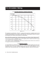
Figure 13.1
The hydraulic specification in Fig 13.1 represent the pressure (available head for the
central heating system) as a function of the flow rate. The pressure loss due to the internal piping in the boiler has already been substracted.
When determining proper piping of the heating system, verify that the internal boiler circulator
will overcome the head loss of the system at the designed flow rate using the graph above.
If the internal circulator is adequate, direct system piping can be utilized. See section 4 page
12 for suggested direct supply/return piping.
If the internal circulator is inadequate, a secondary circulator must be utilized. See sections 14
for suggested primary/secondary piping.
13.2 Expansion vessels:
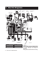
The height difference between the C.h. PRV (19 on page 11) and the highest point in the system may be 23 ft at most. For greater differences, increase the pre-load pressure in the C.h.
expansion vessel (17 on page 11) and the system when cold, by 0.1 bar for additional 3.3 ft. For
systems with volumes greater than 154l, an additional expansion vessel must be provided.
30 RIVA PLUS COMBI MANUAL