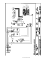
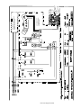
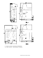
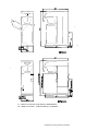
1
COFFEE MAKER
M-Series
TYPE: M200, M202, MT200, MT200V
Installation and Operation Manual
m e t os
t
m e
S/N:
Rev.: 2.2
8.5.2008
Rev. 2.2
Dear Customer,
Congratulations on deciding to choose a Metos appliance for your kitchen activities. You
made an excellent choice. We will do our best to make you a satisfied Metos customer
like thousands of customers we have around the world.
Please read this manual carefully. You will learn correct, safe and efficient working methods in order to get the best possible benefit from the appliance. The instructions and hints
in this manual will give you a quick and easy start, and you will soon note how nice it is
to use the Metos equipment.
All rights are reserved for technical changes.
You will find the main technical data on the rating plate fixed to the equipment. When you
need service or technical help, please let us know the serial number shown on the rating
plate. This will make it easier to provide you with correct service.
For your convenience, space is provided below for you to record your local Metos service
contact information.
METOS TEAM
Metos service phone number:...............................................................................................
Contact person:....................................................................................................................
1
8.5.2008
2
Rev. 2.2
8.5.2008
Rev.
1. General .......................................................................................................... 1
1.1 Symbols used in the manual .......................................................................................... 1
1.2 Symbols used on the appliance ...................................................................................... 1
1.3 Checking the relation of the appliance and the manual ................................................. 1
2. Safety instructions ........................................................................................ 2
2.1 General ..........................................................................................................................
2.1.1 Instructions for use .................................................................................................
2.1.2 Installation .............................................................................................................
2.1.3 Usage .....................................................................................................................
2.1.4 Maintenance and troubleshooting ..........................................................................
2.2 Safeguards .....................................................................................................................
2.2.1 Dry-boil protection (14) .........................................................................................
2.2.2 On/off switch (1) ....................................................................................................
2.2.3 Start/stop button (5.5) ............................................................................................
2.2.4 Jug detector (9) ......................................................................................................
2.2.5 Overflow safeguard ................................................................................................
2.3 Appliances and the environment ...................................................................................
2.3.1 The packing material .............................................................................................
2.3.2 Discarding the appliance ........................................................................................
2
2
2
2
3
3
3
3
4
4
4
4
4
4
3. Functional description .................................................................................. 5
3.1 Use of the appliance ......................................................................................................
3.1.1 Other use ................................................................................................................
3.2 Construction ..................................................................................................................
3.3 Control panel .................................................................................................................
3.3.1 Display ...................................................................................................................
3.3.2 Descale indication light .........................................................................................
3.3.3 Brewing process indicator light .............................................................................
3.3.4 Sound signals .........................................................................................................
3.3.5 Selection button .....................................................................................................
3.3.6 Start/stop button .....................................................................................................
5
5
6
7
7
8
8
8
9
9
4. Operation instructions ............................................................................... 10
4.1 First time use ...............................................................................................................
4.1.1 Daily use ..............................................................................................................
4.2 Operation procedures ...................................................................................................
4.2.1 Making coffee ......................................................................................................
4.2.2 Making tea ...........................................................................................................
4.2.3 Settings .................................................................................................................
4.3 Cleaning of the appliance and accessories ..................................................................
10
11
12
12
12
13
15
1
8.5.2008
4.3.1 Removing coffee deposits from glass jug and filter ............................................
4.3.2 Removing coffee deposits from thermos jug .......................................................
4.3.3 Descaling .............................................................................................................
4.3.4 Switching-off the descale indicator light .............................................................
Rev.
16
16
16
17
5. Installation ................................................................................................... 18
5.1 General ........................................................................................................................
5.1.1 Unpacking ............................................................................................................
5.2 Installation ...................................................................................................................
5.2.1 Preparation for positioning the appliance ............................................................
5.2.2 Electrical connections ..........................................................................................
5.2.3 Connection to the water mains .............................................................................
5.2.4 Water drainage .....................................................................................................
5.2.5 Height setting model MT200V ............................................................................
5.2.6 Setting the descale indicator ................................................................................
5.2.7 Resetting the descale indicator light ....................................................................
18
18
18
18
19
19
19
20
21
21
6. Troubleshooting .......................................................................................... 22
7. Spare parts .................................................................................................. 23
7.1 Voltage codes .............................................................................................................. 25
7.2 Product codes ............................................................................................................... 25
8. Technical specifications .............................................................................. 35
2
8.5.2008
Rev. 2.2
General
1. General
Carefully read the instructions in this manual as they contain important information regarding proper, efficient and safe installation, use and maintenance of the appliance.
Keep this manual in a safe place for eventual use by other operators of the appliance.
The installation of this appliance must be carried out in accordance with the manufacturer’s instructions and following local regulations. The connection of the appliance to the
electric and water supply must be carried out by qualified persons only.
Persons using this appliance should be specifically trained in its operation.
Switch off the appliance in case of failure or malfunction. The periodical function checks
requested in the manual must be carried out according to the instructions. Have the appliance serviced by a technically qualified person authorized by the manufacturer and using
original spare parts.
Not complying with the above may put the safety of the appliance in danger.
1.1
Symbols used in the manual
This symbol informs about a situation where a safety risk might be at hand. Given instructions are mandatory in order to prevent injury.
This symbol informs about the right way to perform in order to prevent bad results, appliance damages or hazardous situations.
This symbol informs about recommendations and hints that help to get the best performance out of the appliance.
1.2
Symbols used on the appliance
This symbol on a part informs about electrical terminals behind the part. The removal of
the part must be carried out by qualified persons only.
1.3
Checking the relation of the appliance and the manual
The rating plate of the appliance indicates the serial number of the appliance. If the manuals are missing, it is possible to order new ones from the manufacturer or the local representative. When ordering new manuals it is essential to quote the serial number shown
on the rating plate.
1
8.5.2008
Rev. 2.2
Safety instructions
2. Safety instructions
2.1
General
This appliance meets the mandatory safety regulations. Inexpert use can result in personal
injury and material damage. The following warnings and safety instructions must be observed before using the coffee maker.
2.1.1
Instructions for use
Read these instructions for use carefully, before using this appliance. This will protect
your safety and prevent damage being caused to the appliance. Perform the various actions in the order given. Always keep this manual in the vicinity of the appliance.
2.1.2
Installation
•
•
•
•
•
•
•
•
•
2.1.3
Usage
•
•
•
•
•
2
Place the appliance at buffet height and on a firm, level base, in such a way that it
can be connected to the water and power supply.
Connect the appliance to an earthed wall socket.
Position the appliance in such a way that no damage can be caused if it leaks.
Do not tilt the appliance, always position and move the appliance upright.
The coffee maker is fitted with an overflow device that discharges at the bottom of
the appliance - take this into account when positioning the appliance.
Water always remains in the heating system: for this reason the appliance must not
be placed in an area where the temperature can fall below freezing point.
When installing the appliance, always observe the local rules and use approved
materials and parts.
The ‘Installation’ chapter must again be followed when repositioning the appliance.
Connect the appliance to the cold water mains.
Inspect the appliance before using it and check it for damage.
Never submerge or spray the appliance.
Do not press the buttons with a sharp object.
Protect the controls against dirt and grease.
It is advisable to take the plug out of the socket and close the water tap if the appliance will not be used for longer periods of time.
8.5.2008
Rev. 2.2
Safety instructions
2.1.4
Maintenance and troubleshooting
•
•
•
•
•
•
•
•
•
Observe the descaling intervals indicated by the descaling indicator light.
Overdue maintenance to the heating system can result in high repair costs and annulment of the guarantee.
Always follow the manufacturer’s instructions when using the descaling agent.
Do not leave the appliance unattended when maintenance is being performed.
When descaling the appliance, it is advisable to wear safety glasses and protective
gloves.
Flush the appliance at least twice after descaling it.
Wash your hands thoroughly after descaling the appliance.
Always have repairs carried out by a qualified service engineer.
The plug must be taken out of the socket if the appliance has to be opened for
cleaning or repairs.
The manufacturer cannot be held liable for losses caused as a result of failure to observe
these safety instructions.
2.2
Safeguards
The appliance is fitted with the following safeguards:
2.2.1
Dry-boil protection (14)
This application is equipped with a dry-boil protection. This protection triggers if the
heating element overheats owing to a fault. Once the fault has been resolved, the dry-boil
protection can be reset at the back of the appliance. The most common cause of the dryboil protection being triggered is not descaling the heating system in time.
If the heating system does not switch back on, proceed as follows:
•
•
•
Allow the appliance to cool down.
Unscrew the protective cap, which can be found on the back of the appliance.
Press the button which is now visible and firmly screw the protective cap back on.
If the dry-boil protection triggers owing to increased scale deposits, descale the appliance.
Consult your dealer if the fault was caused by a problem other than the dry-boil protection
being triggered.
2.2.2
On/off switch (1)
The on/off switch is used to switch the appliance on and off. Remember that the appliance
can still be live after switching it off! For this reason you should always remove the plug
from the socket to render the appliance voltage-free.
3
8.5.2008
Rev. 2.2
Safety instructions
2.2.3
Start/stop button (5.5)
The coffee making process can be interrupted at any point using the Start/stop button located on the control panel.
2.2.4
Jug detector (9)
This appliance is fitted with a jug detector that operates the leak stop under the filter. This
jug detector also ensures that the appliance only makes coffee if there is a jug under the
filter. If the jug is removed during the coffee brewing process, the process will be interrupted and the leak stop in the filter will prevent coffee dripping on the hot plate.
2.2.5
Overflow safeguard
The amount of water required is regulated and monitored by flow and level sensors. If one
of the two sensors detects an irregularity, the appliance switches off and both indicator
lights will flicker.
2.3
2.3.1
Appliances and the environment
The packing material
Your new coffee maker has been carefully packaged to protect it against damage.
The packing is not harmful to the environment and consists of the following materials:
•
•
2.3.2
corrugated cardboard
filler elements made of polyurethane foam <PUR> covered with a polythene film
(>PE-HD<). The waste processing plant in your municipality will be pleased to inform you about where you can dispose of the materials.
Discarding the appliance
No appliance lasts forever. When the time comes to discard your appliance it will usually
be possible to return it to your dealer. If this is not the case, ask your municipal council
about the alternatives for recycling the materials. All plastic parts have been given standard codes. The parts of the appliance such as the printed circuit board and accompanying
parts form electrical and electronic waste. The metal body is made of stainless steel and
can be completely dismantled.
4
8.5.2008
Rev. 2.2
Functional description
3. Functional description
3.1
Use of the appliance
The sole use of this appliance is to make coffee and/or tea, and to warm water.
3.1.1
Other use
The use of the appliance for other purposes is not permitted and may be hazardous. The
manufacturer cannot be held liable for losses caused by using the appliance for purposes
other than those indicated here or by incorrect use.
5
8.5.2008
Functional description
3.2
Construction
m et os
t
m e
6
Rev. 2.2
8.5.2008
Rev. 2.2
Functional description
The most important parts (see pic.):
1.
2.
3.
4.
5.
6.
7.
8.
9.
10.
11.
12.
13.
14.
15.
Appliance on/off switch and bottom hot plate
On/off switch for top hot plate
Basket filter with leak stop device
Basket filter paper
Control panel (see below for details)
Top hot plate
Glass jug/thermos flask
Descaling opening
Jug detector
Bottom hot plate
Type plate
Water drain
Connection cable with plug
Overheating protection
Water connection
Control panel:
•
•
•
•
•
3.3
5.1 Display
5.2 Descale indicator light
5.3 Brewing process indicator light
5.4 Selection button
5.5 Start/stop button
Control panel
Never press the buttons with a sharp object.
Protect the controls against dirt and grease.
3.3.1
Display
The display shows the selected amount of coffee, in terms of cups or litres. While the coffee is being made the display alternately shows the selected amount and the amount of
coffee that has already been made.
7
8.5.2008
Rev. 2.2
Functional description
3.3.2
Descale indication light
The red indicator light will light up if the appliance needs to be descaled. The appliance
will continue to work so that it can be descaled when it is not being used.
3.3.3
Brewing process indicator light
The green indicator light lights up when the coffee passes through the system. At the end
of the coffee making process a signal sounds three times and the green indicator light goes
out. The indicator light flickers if the jug is temporarily removed during the coffee making
process. A signal will also sound indicating that the coffee making process has temporarily stopped.
3.3.4
Sound signals
Sounds three times at the end of the coffee making process. Sounds once if the jug is removed during the coffee making process. A long signal sounds when the appliance is
switched on.
8
8.5.2008
Rev. 2.2
Functional description
3.3.5
Selection button
The selection button is used to reduce the amount of coffee set in the display. When the
lowest value is reached the display returns to the maximum amount.
3.3.6
Start/stop button
The start/stop button is used to start and (emergency) stop the coffee making process.
9
8.5.2008
Rev. 2.2
Operation instructions
4. Operation instructions
4.1
First time use
Ensure that the mains lead does not come into contact with the hot plates (if present).
When used for the first time the appliance works according to the standard factory settings. The various settings can be altered by authorised personell. See chapter ‘Settings’.
•
•
•
•
•
•
•
•
•
•
10
Connect the water connection hose (supplied) to the swivel nut on the back of the
appliance and to manually-operated aeration tap. NB! Only cold water. Open the
water tap and check the connection for leaks.
Slide an empty basket filter (3) into the appliance and place an empty jug (with lid)
underneath it. NB! For the MT200 model leave the lid of the thermos jug with
pump open, and leave the riser tube in the jug. Adjust the height of the MT200V
model before positioning it.
Check if all on/off switches (1+2, if present) are at position 0.
Put the plug in the socket.
Switch on the appliance by setting the on/off switch (1) to the I position, the indicator lights (5.2) and (5.3) will light up and an audible signal will sound. The display (5.1) will then show the preset standard number of cups.
Press the start/stop button and the internal reservoir will fill up. Press the start/stop
button again if water has not started flowing after three minutes.
The green indicator light (5.3) will now light up until the appliance has finished
making the coffee.
When the appliance has finished making the coffee a signal will sound after about
1.5 minutes and the green indicator light (5.3) will go out.
Follow the above steps again for the other coffee making section if the model has
a double coffee making system (M202).
The appliance is ready for use when the jug has been emptied.
8.5.2008
Rev. 2.2
Operation instructions
4.1.1
Daily use
Leak stop
This appliance is fitted with a leak stop that ensures that no coffee drips out of the filter
when you:
•
•
take away the jug after making coffee.
take the filter out of the appliance after making coffee to empty it.
The leak stop can only work if the jug detector is pressed in sufficiently by the jug. If you
use a coffee jug with a narrow neck the jug detector will not be pressed in sufficiently and
the appliance will not start.
Coffee quantity
Basic instructions for brewing coffee:
•
•
•
Use fine ore medium ground coffee.
Keep the jugs and the basket filter clean.
Use only clean and cold water, rich in oxygen
The amount of coffee can be measured using the coffee measuring cup supplied and generally amounts from 35 to 50 grams per litre. Before you start using the applience you
should make an objective flavour test in order to establish the right amount of coffee and
water needed. The adjoining list gives guide lines for the ground coffee amount needed
using different jug sizes.
Jug
Glass jug
Thermos jug
Thermos jug with pump
Thermos container
Content
Coffee
1.8 litres
100-125 grams
1.8 litres
100-125 grams
2.2 litres
100-150 grams
2.4 litres
150-180 grams
11
8.5.2008
Rev. 2.2
Operation instructions
4.2
4.2.1
Operation procedures
Making coffee
•
•
•
•
•
•
•
Place a sheet of basket filter paper containing the desired amount of coffee (fast
filter type) in the basket filter. See the table above for the amount of coffee required. A level coffee measure is approximately 80 grams.
Slide the basket filter (1) into the appliance.
Then place the jug, with the lid on it, under the filter. With the MT200 model, open
the lid of the thermos jug with pump and leave the riser tube in the jug.
Switch on the appliance using the on/off switch (1). The lamp in the switch will go
on and the lower hot plate will switch on.
Select the desired amount in the display (5.1) using the selection button (5.4).
Press the start/stop button, the green indicator light (5.3) will switch on and the appliance will start making coffee. While the appliance is making coffee the display
(5.1) will alternately show the selected quantity and the amount of coffee that has
already been made.
Once the coffee brewing process has been completed the green indicator light (5.3)
will go out and an audible signal will sound three times, indicating that the coffee
is ready. Once the filter has been cleaned you can immediately resume making coffee.
Warning! Do not remove the jug untill the indicator light has gone out and the audiable signal has been given.
•
•
4.2.2
Pour out the coffee or place the jug on the top hot plate (8) (except for the MT models). The top hot plate is switched on separately using on/off switch (2). Always
switch off the extra hot plate when it is not being used.
After cleaning the basket filter the appliance can immediately be used to make the
next serving of coffee.
Making tea
This appliance can of course also be used to make tea using tea bags.
•
•
•
12
Basic rule: never use a basket filter or a (thermos) jug that has already been used
to make coffee. The coffee remnants will adversely affect the flavour of the tea.
To make tea you should therefore always use a separate glass jug/thermos jug and
basket filter that have not been used to brew coffee!
Place the tea bags in the basket filter without using a paper filter of place/hang
them in the jug. Tea is made using the same method as for brewing coffee, but
without using paper filters or coffee.
8.5.2008
Rev. 2.2
Operation instructions
4.2.3
Settings
The jug will overflow if the set coffee quantity is too high.
The manufacturer is unable to accept any liability for the consequences of altered settings.
Setting of the amount of coffee
Both the M and the MT models are supplied as standard set to make coffee using 1,8 litres
of water (14 cups). If this is too much or too little, or if you are using an MT model in
combination with a thermos jug with a greater capacity, you can adjust the quantity as follows:
•
•
•
•
Press the selection button (5.4) and hold it in, and then press the start/stop button
(5.5) once. A number will appear in the display.
Release both buttons. The display will show the set value. The standard setting is
20 (1.8 l. / 14 cups).
Press the selection button (5.4) to increase the amount. Each increase in the display
puts approximately 4 ml more water in the jug. Use the table beside. To reduce the
quantity: go through the table until it restarts after 50. The range runs from
0,1,2,3,4 ..... 50.
Now wait for 6 seconds. The selected quantity is now saved.
13
8.5.2008
Operation instructions
14
Rev. 2.2
8.5.2008
Rev. 2.2
Operation instructions
Setting of the display to show cups or litres
The appliance is factory set to display the number of cups. If you want the display to show
litres, you can adjust it as follows:
•
•
•
•
Press the selection button (5.4) and hold it in, the press the start/stop button (5.5)
once. A number will appear in the display.
Release both the buttons and then press the start/stop button once again.
A “C” (Cups) will appear in the display. Change the “C” to an “L” with the selection button.
Now wait for 6 seconds. The adjustment has now been saved.
Setting the prewet function
This appliance can make coffee using two methods:
•
•
Continue-brew (“Cb”) (factory setting); The coffee making process begins immediately and will pour hot water over the ground coffee without a waiting time.
Prewet-brew (“Pb”); part of the hot water is first poured onto the ground coffee.
This causes the coffee to rise so that the smells and flavours are released. The coffee making process then begins.
If you want to set the appliance to Prewet brew, this setting can be changed as follows:
•
•
•
•
4.3
Press the selection button (5.4) and hold it in. Then press the start/stop button once.
A number will appear in the display.
Release both buttons and then press the start/stop button twice. “Cb” (Continuebrew) will appear in the display.
Use the selection button to change “Cb” into “Pb” (Prewet brew).
Now wait for 6 seconds. The adjustment has now been saved.
Cleaning of the appliance and accessories
The appliance must not be submerged or sprayed.
•
•
•
•
•
Clean the outside of the appliance with a clean, damp cloth, if necessary using mild
(non-abrasive) cleaning agent.
Do not use an abrasive, as this will leave scratches and dull patches.
The glass jugs and the basket filter can be washed normally and rinsed clean.
Please note, however, that it is inadvisable to clean the basket filter in an industrial
dish washer as its lightness may cause it to float and sustain damage.
The thermos jug, thermos jug with pump and the filter can be rinsed with hot water.
The coffee deposit in the coffee jugs and the filter can be cleaned with coffee fur
remover.
15
8.5.2008
Rev. 2.2
Operation instructions
4.3.1
Removing coffee deposits from glass jug and filter
•
•
•
•
4.3.2
Removing coffee deposits from thermos jug
•
•
•
•
4.3.3
Fill a tray with approx. 5 litres of warm water and dissolve a sachet (10 gr) of coffee fur remover in it.
Place the parts you want to clean in this solution and leave them to soak for 15 to
30 minutes.
Then rinse them several times with hot water, and repeat when necessary.
Sprinkle the powder on to heavily soiled parts and clean them with a wet brush.
Dissolve a quantity of coffee fur remover in warm water: use approx. 2 grams per
litre.
Fill the thermos jug with this solution.
Leave the solution to soak for 15 to 30 minutes. Pump the solution out of the pump
thermos, turn the tap of the thermos cistern on.
Brush the inner jug clean carefully and rinse well with hot water. Clean the tap and
measuring glass of the thermos cistern with a narrow bottle brush.
Descaling
Stay close to the appliance when performing maintenance. It is advisable to wear safety
glasses and protective gloves when descaling the appliance. Flush the appliance at least
two times after descaling it. Wash your hands thoroughly after descaling the appliance.
Observe the descaling intervals indicated by the descale indicator light. Overdue maintenance to the heating system can result in high repair costs and annulment of the guarantee.
Scale deposits are left in the heating system when the appliance is used. The amount of
scaling depends on the hardness of the water being used. The appliance is fitted with a
descale indicator light (5.2), which lights up when the heating system has processed a certain quantity of water and has to be descaled. The appliance continues to work so that it
can be descaled when it is not being used.
•
•
•
•
•
•
•
•
•
16
Before descaling the appliance, carefully read the instructions for use of the scale
remover.
Slide an empty sheet of basket filter paper into the basket filter and place an empty
jug under it.
Remove the cap (8) and place the funnel (supplied) into the descaling opening.
Dissolve one 50 gram sachet of scale remover in 0.5 litre of warm water (approx.
60-70ºC).
Carefully pour half of the solution into the descaling opening (8) using the funnel.
Switch on the appliance using the switch (1). Select 2 cups using the selection button (5.4) and press the start/stop button (5.5). The solution will now run through
the heating system and discharge into the jug.
Wait until the ‘coffee ready’ signal sounds. The solution will now react with the
deposits in the heating system.
After the waiting time, repeat points 5 and 6.
Wash away the solution in the jug once the filter has finished dripping.
8.5.2008
Rev. 2.2
Operation instructions
•
•
•
•
4.3.4
Remove the funnel and replace the cap.
After descaling the appliance, flush the system by following the coffee brewing
procedure twice but without using filter paper or coffee. Remember to empty the
jug in the meantime.
Switch off the appliance and thoroughly clean the basket filter and the jug.
The appliance is now ready for use.
Switching-off the descale indicator light
•
•
Press the programme button (5.4) for 6 seconds; the descale indicator light (5.2)
will go out.
The control system resumes registering the number of brewing processes.
17
8.5.2008
Rev. 2.2
Installation
5. Installation
5.1
5.1.1
General
Unpacking
The machine has been carefully packed to prevent damage being caused to your new coffee maker. Remove the packing carefully without using sharp objects. Check if the appliance is complete. The appliance is delivered with the following accessories:
Glass jug
Basket filter
Filter paper (25 pcs.)
Coffee measuring cup
Water measuring cup
Funnel
Water connection hose
Manual
M 200
M 202
MT 200
MT 200V
2
1
1
1
1
1
1
4
2
1
1
1
1
1
1
1
1
1
1
1
1
1
1
1
1
1
1
1
Please contact your dealer if any parts are missing or damaged.
5.2
5.2.1
Installation
Preparation for positioning the appliance
Water always remains in the heating system: for this reason the appliance must not be
placed in an area where the temperature can fall below freezing point.
•
•
•
•
•
18
Position the appliance at buffet height on a firm, level base that can bear the weight
of the appliance when it is filled.
Position the appliance level and in such a way that it cannot cause any damage if
it leaks.
The water supply pipe (G3/4” pipe 15 mm) and the power connection must be located within a half metre of the appliance.
The owner must have these installation-technical preparations performed by qualified engineers in accordance with general and local regulations.
The service engineer may only connect the appliance to the prepared connections.
8.5.2008
Rev. 2.2
Installation
5.2.2
Electrical connections
Supply voltages and frequencies can differ between countries. Check if the appliance is
suitable for connection to the local power mains. Check if the details on the type plate correspond. Connect the appliance to an earthed wall socket.
5.2.3
Connection to the water mains
Connect the appliance using the water hose to an easily accessible cold water tap that can
be quickly closed if problems arise.
5.2.4
Water drainage
If the reservoir is overfilled owing to a defect, the excess water will be discharged via the
water drain at the bottom of the appliance. Make allowance for this when positioning the
appliance.
19
8.5.2008
Rev. 2.2
Installation
5.2.5
Height setting model MT200V
The MT200V model is in height adjustable. Follow the steps below to optimally set the
appliance to the height of the thermos flask being used.
•
•
•
•
•
•
•
20
Slide the basket filter (1) into the appliance.
Grasp the top part of the appliance and turn the adjustment button (2) a half-turn
anti clockwise.
Lift the top part of the appliance upwards.
Place the thermos jug you intend to use at the base of the appliance.
Now slowly allow the top section to go down until the marking line (3) on the column is level with the top side of the thermos jug. (This column height adjustment
must be done with the top open if the appliance is used in combination with a thermos jug with a pump).
Tighten the adjustment button (clockwise).
After repositioning, check if the thermos jug properly presses in the jug detector
handle (4) (the green indicator light (5.3) must not blink when a coffee making
process begins).
8.5.2008
Rev. 2.2
Installation
5.2.6
Setting the descale indicator
Scale deposits are left in the heating system when the appliance is used. The amount of
scaling depends on the hardness of the water being used. The appliance is fitted with a
descale light (5.2), which lights up when the heating system has processed a certain quantity of water and has to be descaled. The appliance continues to work so that it can be descaled when it is not being used.
Water
hardness
If you are unaware of the hardness of your mains water, you are advised to contact your
local water supply company.
Set the appliance to your water hardness as follows, using the table above as a guideline.
•
•
•
•
5.2.7
Switch off the appliance (1).
Hold in the programme button (5.4) and switch the appliance back on.
Press the programme button (5.4) until the right indicator light (5.2/5.3) lights up.
(E.g. only the red lamp should light up for hard water. The water in the area is hard,
over 12 ºD ).
Wait for 6 seconds. The water hardness has now been set.
Resetting the descale indicator light
After the descaling procedure (see chapter ‘Descaling’) hold in the programme button for
6 seconds. The descaling indicator light will now go out.
21
8.5.2008
Rev. 2.2
Troubleshooting
6. Troubleshooting
Have all repairs to the electrical system performed by a qualified service technician.
If your appliance is not functioning correctly, use the troubleshooting guide below to see
whether you can resolve the problem yourself. If not, please contact your dealer.
Symptom
Possible cause
Action
The appliance is not working and the
lamps in the switch are not lighting up
The brewing process indicator light is
flickering, no water is getting into the
filter.
The fuse in the fuse box has been triggered, the group is too loaded heavily.
The jug indicator is not registering a
jug. There is no jug under the filter, the
wrong coffee jug is being used or the
height adjustment of the MT200V
model is incorrect.
The dry-boil protection has been triggered.
Replace the fuse or reset it. Connect
the appliance to a separate group.
Position a jug, use the correct jug or readjust the height of the appliance.
The scaling deposits in the heating system exceed the set limit.
The appliance has not yet been reset.
Descale the appliance.
The brewing process indicator light is
on, but no water is getting into the filter.
The descale indicator light has come
on.
The descale indicator light remains on
after descaling the appliance.
Steam coming from the filter.
Coffee is dripping out of the filter
when there is no jug under it.
The coffee is too strong.
The coffee is too weak.
The coffee is not hot enough
The jug is too full or is overflowing.
Not enough coffee is getting into the
jug.
E1 (filling time error).
An E2, 3, 4, 5, 6 appears in the display
and both indication lights flicker.
22
The appliance was not descaled when
indicated by the descaling indicator
light or the wrong water setting has
been applied.
The leak stop valve on the outlet of the
filter is soiled or damaged.
Too much coffee has been placed in
the filter.
Not enough coffee has been placed in
the filter.
The water distributor is soiled, so that
the coffee is not being completely
drenched.
There is no lid on the jug
The set quantity is too high.
The set quantity is too low.
Appliance fills too slowly, the water
supply is blocked.
The control unit is reporting a defect
that can only be resolved by a service
technician.
Reset the dry-boil protection.
Press the programme button for 6 seconds. The light will go out.
Descale the appliance.
Clean the filter and check the leak stop
valve for damage.
Reduce the amount of coffee.
Increase the amount of coffee.
Unscrew the water distributor and
clean it.
Use the lid.
Lower the quntity.
Increase the quantity.
Check the water supply. Fully open the
tap. Increase the water pressure.
Switch the appliance on and off. The
error report will disappear.
Contact dealer or service technician.
8.5.2008
Rev. 2.2
Spare parts
7. Spare parts
General parts M200 ............................. 27
General parts M202 ............................. 29
General parts MT200........................... 31
General parts MT200V ........................ 33
23
8.5.2008
Spare parts
24
Rev. 2.2
8.5.2008
Rev. 2.2
Spare parts
Voltage code
Voltage
A
3/N/PE∼400/230V 50Hz
B
∼250V 16A 50Hz
C
3/N/PE∼380/220V 50Hz
D
3/PE∼200V 50-60Hz
F
2/PE 220−240V 50Hz
G
3/N/PE∼415/240V 50Hz
H
3/PE∼230V 50Hz
I
3/PE∼220V 60Hz
J
3/PE∼380 50Hz
K
3/PE∼400V 50Hz
L
3/PE∼415V 50Hz
M
3/PE∼440V 60Hz
N
3/PE∼460V 60Hz
O
3/PE∼480V 60Hz
P
1/N/PE~220-240V 50Hz
R
2/PE~220-230V 60Hz
S
3/N/PE∼400/230V 50Hz
T
3/PE∼230V 60Hz
Product code
7.1
Voltage codes
7.2
Product codes
Full name
Model codes
Type codes
M200
M200
M202
M202
MT200
MT200
MT200V
MT200V
Accessory codes
25
26
280
60
330
30
190
90
310
180
320
170
m200e.cgm
300
110+120
20
100
200
70
240
150
340
270
140
290
40
250
130
230
210
50
80
10
260
220+160
350
360
276
273
Spare parts
8.5.2008
Rev. 2.2
8.5.2008
Rev. 2.2
Spare parts
ID
Code
Type
Description
MODULE:General parts M200
10
02180
M200
Switch 1P, orange
20
02267
M200
RC-network
30
02571
M200
Cable strain relief
40
02887
M200
Pc board M200
50
02889
M200
Pc board M200 keyboard
60
02929
M200
Dry-boil protection
70
02930
M200
Level sensor M
80
02938
M200
O-ring 92.75x2.62 EPDM
90
02947
M200
Solenoid M200 220-240V 50-60Hz
100
02949
M200
Flowmeter
110
02970
M200
Safety plate element
120
02971
M200
Safety plate
130
05035
M200
Metal screw
140
05131
M200
Faston tab
150
05328
M200
Wire protector clip
160
05361
M200
Nut
170
05380
M200
Wire protector clip
180
07155
M200
Tube clamp
190
07248
M200
Tube clamp
200
07936
M200
Water reservoir
210
07937
M200
Basket filter guide, left
220
07939
M200
Spraying tank
230
07940
M200
Water distributor
240
07941
M200
Foot
250
07945
M200
Pc board fixing box
260
07950
M200
Basket filter guide, right
270
08088
M200
Plug for base plate
273
08630
M200
Jug
276
08970
M200
Lid
280
12706
M200
Element 2100W 230V M
290
12780
M200
Hot plate self-regulating
300
35014
M200
Tube silicone
310
35036
M200
Tube silicone
320
35038
M200
Tube silicone
330
35057
M200
Tube silicone
340
99231
M200
Jug detector
350
99233
M200
Leak stop flap
360
12207
M201
Filter funnel
27
28
670
460
730
580
430
560
m202e.cgm
500+510
690
700
720
410
490
570
710
590
470
420
540
740
660
530
680
440
640
520
620
600
450
480
400
650
610+550
750
760
667
663
Spare parts
8.5.2008
Rev. 2.2
8.5.2008
Rev. 2.2
Spare parts
ID
Code
Type
Description
MODULE:General parts M202
400
02180
M202
Switch 1P, orange
410
02267
M202
RC-network
420
02571
M202
Cable strain relief
430
02702
M202
Solenoid double 220-240V 50-60
440
02887
M202
Pc board M200
450
02889
M202
Pc board M200 keyboard
460
02929
M202
Dry-boil protection
470
02930
M202
Level sensor M
480
02938
M202
O-ring 92.75x2.62 EPDM
490
02949
M202
Flowmeter
500
02970
M202
Safety plate element
510
02971
M202
Safety plate
520
05035
M202
Metal screw
530
05131
M202
Faston tab
540
05328
M202
Wire protector clip
550
05361
M202
Nut
560
05380
M202
Wire protector clip
570
07155
M202
Tube clamp
580
07248
M202
Tube clamp
590
07936
M202
Water reservoir
600
07937
M202
Basket filter guide, left
610
07939
M202
Spraying tank
620
07940
M202
Water distributor
630
07941
M202
Foot
640
07945
M202
Pc board fixing box
650
07950
M202
Basket filter guide, right
660
08088
M202
Plug for base plate
663
08630
M202
Jug
667
08970
M202
Lid
670
12707
M202
Element 1600W 230V M
680
12780
M202
Hot plate self-regulating
690
35014
M202
Tube silicone
700
35036
M202
Tube silicone
710
35038
M202
Tube silicone
720
35043
M202
Tube silicone
730
35057
M202
Tube silicone
740
99231
M202
Jug detector
750
99233
M202
Leak stop flap
760
12207
M203
Filter funnel
29
30
1060
850
1100
965
880
820
mt200e.cgm
1070
900+910
1080
830
1030
960
1090
810
890
970
860
950
1010
930
1110
1050
1020
800
920
1000
980
840
870
1040
990+940
1120
Spare parts
8.5.2008
Rev. 2.2
8.5.2008
Rev. 2.2
Spare parts
ID
Code
Type
Description
MODULE:General parts MT200
800
02180
MT200
Switch 1P, orange
810
02267
MT200
RC-network
820
02571
MT200
Cable strain relief
830
02887
MT200
Pc board M200
840
02889
MT200
Pc board M200 keyboard
850
02929
MT200
Dry-boil protection
860
02930
MT200
Level sensor M
870
02938
MT200
O-ring 92.75x2.62 EPDM
880
02947
MT200
Solenoid M200 220-240V 50-60Hz
890
02949
MT200
Flowmeter
900
02970
MT200
Safety plate element
910
02971
MT200
Safety plate
920
05035
MT200
Metal screw
930
05328
MT200
Wire protector clip
940
05361
MT200
Nut
950
05380
MT200
Wire protector clip
960
07155
MT200
Tube clamp
965
07248
MT200
Tube clamp
970
07936
MT200
Water reservoir
980
07937
MT200
Basket filter guide, left
990
07939
MT200
Spraying tank
1000
07940
MT200
Water distributor
1010
07941
MT200
Foot
1020
07943
MT200
Switch holder
1030
07945
MT200
Pc board fixing box
1040
07950
MT200
Basket filter guide, right
1050
08088
MT200
Plug for base plate
1060
12706
MT200
Element 2100W 230V M
1070
35029
MT200
Tube silicone
1080
35037
MT200
Tube silicone
1090
35038
MT200
Tube silicone
1100
35058
MT200
Tube silicone
1110
99231
MT200
Jug detector
1120
99233
MT200
Leak stop flap
31
1230
1420
32
1460
1250
1500
1280
1350
1480
1210
1260
mt200ve.cgm
1470
1300+1310
1290
1490
1510
1440
1450
1360
1320
1390
1240
1270
1430
1380+1330
1520
1530
1220
1400
1410
1200
Spare parts
8.5.2008
Rev. 2.2
8.5.2008
Rev. 2.2
Spare parts
ID
Code
Type
Description
MODULE:General parts MT200V
1200
02180
MT200V
Switch 1P, orange
1210
02267
MT200V
RC-network
1220
02571
MT200V
Cable strain relief
1230
02887
MT200V
Pc board M200
1240
02889
MT200V
Pc board M200 keyboard
1250
02929
MT200V
Dry-boil protection
1260
02930
MT200V
Level sensor M
1270
02938
MT200V
O-ring 92.75x2.62 EPDM
1280
02947
MT200V
Solenoid M200 220-240V 50-60Hz
1290
02949
MT200V
Flowmeter
1300
02970
MT200V
Safety plate element
1310
02971
MT200V
Safety plate
1320
05035
MT200V
Metal screw
1330
05361
MT200V
Nut
1340
05380
MT200V
Wire protector clip
1350
07248
MT200V
Tube clamp
1360
07936
MT200V
Water reservoir
1370
07937
MT200V
Basket filter guide, left
1380
07939
MT200V
Spraying tank
1390
07940
MT200V
Water distributor
1400
07941
MT200V
Foot
1410
07943
MT200V
Switch holder
1420
07945
MT200V
Pc board fixing box
1430
07950
MT200V
Basket filter guide, right
1440
08088
MT200V
Plug for base plate
1450
08306
MT200V
Knobb star
1460
12706
MT200V
Element 2100W 230V M
1470
35014
MT200V
Tube silicone
1480
35028
MT200V
Tube silicone
1490
35034
MT200V
Tube silicone
1500
35057
MT200V
Tube silicone
1510
99231
MT200V
Jug detector
1520
99233
MT200V
Leak stop flap
1530
12207
MT200V
Filter funnel
33
8.5.2008
Spare parts
34
Rev. 2.2
8.5.2008
Rev. 2.2
Technical specifications
8.
Technical specifications
Electrical diagram M200
Electrical diagram M202
Electrical diagram MT200
Electrical diagram MT200v
Installation drawing M200, M202
Installation drawing MT200, MT200V
35
Electrical diagram M200
blå. sininen.
brun. ruskea
gul. keltainen.
grön. vihreä.
grå, harmaa.
orange. oranssi
purpur. purppura
röd. punainen
pink. vaaleanpunainen
vit. valkoinen
svart. musta
Electrical diagram M202
Circuit diagram left
Kretsschema vänster
Piirikaavio vasen
Circuit diagram right, see left
Kretsschema höger, titta på vänster
Piirikaavio oikea, katso vasen
blå. sininen.
brun. ruskea
gul. keltainen.
grön. vihreä.
grå, harmaa.
orange. oranssi
purpur. purppura
röd. punainen
pink. vaaleanpunainen
vit. valkoinen
svart. musta
Electrical diagram MT200
blå. sininen.
brun. ruskea
gul. keltainen.
grön. vihreä.
grå, harmaa.
orange. oranssi
purpur. purppura
röd. punainen
pink. vaaleanpunainen
vit. valkoinen
svart. musta
Electrical diagram MT200v
blå. sininen.
brun. ruskea
gul. keltainen.
grön. vihreä.
grå, harmaa.
orange. oranssi
purpur. purppura
röd. punainen
pink. vaaleanpunainen
vit. valkoinen
svart. musta
E = Electric connection / Elanslutning / Sähköliitäntä
W = Water connection / Vattenanslutning / Vesiliitäntä
Installation drawing M200, M202
E = Electric connection / Elanslutning / Sähköliitäntä
W = Water connection / Vattenanslutning / Vesiliitäntä
Installation drawing MT200, MT200V
8.5.2008
Technical specifications
Item
Type
Specification
Buffer stock coffee
M200
3.6 l. / 28 cups
Buffer stock coffee
M202
7.2 l. / 56 cups
Hourly coffee capacity
M200,MT200,MT200V
18 l. / 144 cups
Hourly coffee capacity
M202
28 l. / 224 cups
Jug filling time
M200
approx. 6 min.
Jug filling time
M202
approx. 8 min.
Jug filling time
MT200,MT200V
approx. 7.5 min./ 2.2 l.
Coffee amount
M200,M202,MT200,MT200V
1 - 3 l.
Supply voltage
M200,M202,MT200,MT200V
220-240V
Frequency
M200,M202,MT200,MT200V
50-60Hz
Total output
M200
2250W
Total output
M202
3500W
Total output
MT200,MT200V
2100W
Filter paper
M200,M202,MT200,MT200V
90 / 250
Min. water pressure
M200,M202,MT200,MT200V
0.02 Mpa (0.2 bar)
Max. water pressure
M200,M202,MT200,MT200V
1 Mpa (10 bar)
Empty weight
M200,MT200
6.6 kg
Empty weight
M202
11 kg
Empty weight
MT200V
8 kg
Transport dimensions (LxWxH)
M200
600x275x520 mm
Transport dimensions (LxWxH)
M202
600x450x520 mm
Transport dimensions (LxWxH)
MT200,MT200V
445x275x665 mm
42
Rev. 2.2