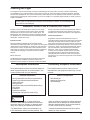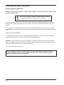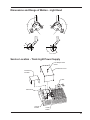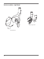
1
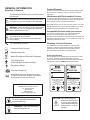
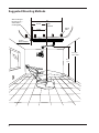
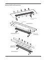
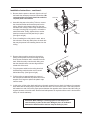
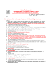
TL 500 Track Light
Owner’s Manual
Marus
11727 Fruehauf Drive
Charlotte, NC 28273 USA
Technical Support: 800-304-5332
FAX: 888-861-9366
Warranty
All of our products sold to and installed by dealers are guaranteed to be free from defects in workmanship
and materials for five years from date of purchase. Upholstery is warranted for a period of one year from
the date of purchase. During that period, we will replace any defective part at no charge. We WILL NOT
be responsible for dealer or service company labor charges or shipping charges to the factory.
This guarantee does not cover normal wear, stains, cuts or scratches of upholstery or surface finishes or
parts sold to OEM customers.
Staining, discoloration or deterioration of the equipment caused by disinfectant solutions is not covered
under the warranty.
We will pay the return freight charges from the factory to the dealer. This guarantee does not cover damage resulting from improper installation, misuse or accidents incurred in shipping and handling.
All claims against the freight carrier must be initiated at the time the damaged items are received. The
claim is the responsibility of the customer.
We are constantly striving to improve our products. We reserve the right to make modifications without
the need for prior notification and are not obliged to modify previously manufactured items.
Fiber optic system note: Units equipped with the optional fiber optic system are covered under the five
year warranty, although the bulbs are items not covered under warranty and must be purchased.
It is the user’s responsibility to read and understand the contents of this manual. This
manual contains important information relative to hazards to personnel and property if
this equipment is not installed, used and/or maintained as instructed.
11727 Fruehauf Drive
Charlotte, NC 28273 USA
Technical Support: 800-304-5332
FAX: 888-861-9366
92353 • Rev. 5 • 02/12
Table of Contents
General Information and Warnings.......................................................................................................2
Definition of Symbols......................................................................................................................2
Product Disposal............................................................................................................................2
Interference with Electromedical Devices.......................................................................................2
Incompatible Devices and/or Accessories......................................................................................2
Obtaining Technical Literature........................................................................................................2
Safety Notes.........................................................................................................................................3
Storage Conditions.........................................................................................................................3
Technical Specifications for the Dental Light........................................................................................4
Technical Description — Light........................................................................................................4
Electrical Specifications..................................................................................................................4
Light Specifications.........................................................................................................................4
Replacement Parts for Dental Lights..............................................................................................4
Safety Markings..............................................................................................................................4
Device Classification......................................................................................................................4
Overview / Replacement Parts.............................................................................................................5
Suggested Mounting Methods..............................................................................................................6
Suggestions for Suspended Ceiling.....................................................................................................7
Mounting Parallel and Perpendicular..............................................................................................9
Electrical Requirements.....................................................................................................................10
Installation Instructions.......................................................................................................................10
Adjusting the Light-head’s Horizontal Rotation...................................................................................13
Adjusting the Light-head’s Vertical Rotation.......................................................................................13
Adjusting the Light-head’s Third Axis Rotation..................................................................................14
Focusing the Light..............................................................................................................................14
Turning the Light On and Off..............................................................................................................14
Replacing the Bulb.............................................................................................................................15
Adjusting the Auto-Switch(Optional)...................................................................................................16
Flex Arm Adjustment..........................................................................................................................16
Vertical..........................................................................................................................................16
Horizontal.....................................................................................................................................16
Cleaning the Light..............................................................................................................................17
WARNINGS, DISINFECTING & STERILIZATION - LIGHTS.......................................................17
Unacceptable Disinfectants..........................................................................................................17
Conditionally Acceptable Disinfectants*.......................................................................................17
Cleaning Reflector and Cover......................................................................................................18
Dimensions and Range of Motion - TL 500 Track Light.....................................................................19
Dimensions and Range of Motion - Light Head..................................................................................21
Service Location - Track Light Power Supply.....................................................................................21
Service Location - Light Head............................................................................................................22
Electrical Schematics.........................................................................................................................23
Electromagnetic Compatibility............................................................................................................25
Checklist.............................................................................................................................................29
1
GENERAL INFORMATION
Definition of Symbols
The following symbols may be used throughout
this manual:
CAUTION. Failure to carefully follow the described
procedure may result in damage to the equipment.
WARNING. Failure to carefully follow the described
procedure may result in damage to the equipment
and/or operator/patient injury.
Risk of electrical shock present.
Ensure power is disconnected before attempting
this procedure.
AC (Alternating Current)
Protective Earth (Ground)
Product Disposal
Contact your local authorized dealer for proper disposal of the
device to ensure compliance with your local environmental
regulations.
Interference with Electromedical Devices
To guarantee the operational safety of electromedical devices, it
is recommended that the operation of mobile radio telephones
in the medical practice or hospital be prohibited.
Strong EMI sources such as electro surgery units or x-ray units
may affect performance. If performance problems occur, move
the light to another electrical circuit or physical location.
Incompatible Devices and/or Accessories
For reasons of product safety, only original manufacturer
devices & accessories approved for this product, or
accessories from third parties which have been released by the
manufacturer may be used. It is the user’s risk when using nonreleased accessories are used.
Obtaining Technical Literature
The manufacturer will make available on request circuit
diagrams, component parts lists, descriptions, calibration
instructions or other information that will assist technical
personnel to repair and replace serviceable items.
Manufacturing date
Waste Electrical and Electronic Equipment
Type B Equipment
(Protected against electrical shock)
Product Identification
This dental light can be identified by its product label, located
on product. This label states the light model and serial
number, electrical specifications, manufacture date and safety
classification. Note the SAMPLE labels shown below.
Dangerous Voltage
Marus
Electrical Testing Lab
Identification mark that indicates the product
complies with the health & safety requirements
as published by European Directives.
WARNING: This product is intended
for use by trained dental/medical
professionals only.
WARNING: This product must be
disinfected before use.
2
Dental Light
11727 Fruehauf Drive
Charlotte, NC 28273 USA
MN
SN
115 VAC, 60HZ, 1.09A
IEC Type B, Class 1, IPX4
Operation Mode: Intermittent
Conforms to:
EN60601-1-2,UL60601-1
Certified to:
CAN/CSA - C22.2 NO.601.1
59768
Dental Light
230 VAC, 50HZ, 0.6A
IEC Type B, Class 1, IPX4
92163 • Rev.5 • 02/12
Medical Device and QA Services
76, Stockport Road
WA15 7SN
United Kingdom
e-mail: [email protected]
MN
SN
92162• Rev.5 •02/12
Authorized European Representative:
Marus
11727 Fruehauf Drive
Charlotte, NC 28273 USA
Operation Mode: Intermittent
Conforms to:
EN60601-1-2,UL60601-1
Certified to:
CAN/CSA - C22.2 NO.601.1
59768
CAUTION: Only authorized service technicians should attempt
to service this equipment.
Use of other than authorized
technicians will void the
warranty.
SAFETY NOTES
The pre-installation must be performed according to the requirements in our ‘Pre-installation Instructions’.
As manufacturers of electro-medical products we can assume responsibility for safety-related performance of
the equipment only if maintenance, repair and modifications are carried out only by us or agencies we have
authorized for this purpose, and if components affecting safe operation of the unit that may be needed are
replaced with original parts.
We suggest that you request a certificate showing the nature and extent of the work performed, from those
who carry out such work, and specify that the certificate show any changes in rated parameters or working
ranges, as well as the date, the name of the firm and a signature.
Storage Conditions:
-55°C to +50°C
10% to 90% Relative Humidity
WARNING: Rotational stops are
designed for a maximum force limit of
30 lbs. If rotational stops are broken
immediately take the equipment out of
use and have the equipment serviced.
Operation of damaged equipment
could result in injury to the operator
and/or patient.
WARNING: Failure to install set
screws & roll pin per Installation
Instructions could result in injury or
damage to equipment.
WARNING: The light is not to be used
in rooms where an explosion hazard
exists.
WARNING: Power cords and their
associated parts cannot be substituted
without increase risk of electric shock
or fire. Use manufacturer-approved
replacement parts only! Power
cords must be installed by qualified
personnel. Make sure all service
loops, strain reliefs, and cord guards
are in place and that line, neutral
and ground wires are secured.
CAUTION: Only authorized service technicians should attempt to service
this equipment. Use of other than
authorized technicians will void the
warranty.
WARNING: Failure to disinfect the
dental operating light between patients
could expose user/patient to cross
contamination and bio-burden/biocontamination.
WARNING: No modification of this
equipment is allowed.
CAUTION! Use a licensed electrician
for all wiring.
WARNING: To avoid risk of electric
shock, this equipment must be
connected only to supply mains with
protective earth.
WARNING: To avoid risk of burn injuries
do not touch the light reflector during
operation.
WARNING: To avoid risk of injury, avoid
contact with sharp edges on dental
lights.
WARNING: To avoid risk of injury, avoid
contact with sharp edges on dental
lights.
3
Technical Specifications for the Dental Light
Technical Description — Light
The dental light is used for illuminating the oral
cavity during the performance of dental procedures.
The position and direction of the light can be adjusted
as needed by the dentist. The light source is a halogen
bulb designed to operate on low voltage. It has two
intensity settings. The low voltage is supplied through a
transformer which is located at the top of the light pole
or in the junction box.
Patent Pending for DCI Equipment Light Head
Replacement Parts for Dental Lights
The following represents a condensed list of
replacement parts that may be consumed during
normal use. See your dealer for a more comprehensive list of components.
PART #
DESCRIPTION
70-22186���������������� REFLECTOR, GLASS
70-20289���������������� LIGHT SHIELD
70-30441���������������� REPLACEMENT BULB
70-014R304������������ FUSE, 4 AMP, 3 AG (115V)
70-014R303������������ FUSE, 2 AMP, 3 AG (230V)
Safety Markings
The following warning label may be located
on or near the light’s transformer enclosure:
Electrical Specifications
Volts Dental light: 115 VAC
230 VAC
Cycles
60 HZ
50 HZ
Amps
1.09 A ~
0.6 A ~
Replacement fuses for unit light
(located in panel near transformer):
115V: 4 AMP, 3 AG (P/N 70-014R304)
230V: 2 AMP, 3 AG (P/N 70-014R303)
IEC Medical Device Classification
Classification:
1
Type:
B
Operation Mode:
Intermittent
Splash Protection:
IPX4
Light Specifications
Halogen Lamp: 24 Volts, 100 Watts
Input Voltage: 110V/220 V, 60/50 Hz
Output Voltage: High 23V, Low 21V
Color Temperature: 4500 Degrees Kelvin
Light Intensity (Lux): High 25,000, Low 18,500
4
Focal Distance: 27 in.
Illumination Area: 3 in. x 8 in. at Focal Distance
Approx. Weight: 9.09 kg. (20 lbs.)
Device Classification
The dental light is classified as
Class 1 device under rule FDA
CFR 21, Class I device under
Health Canada guidelines, and a
Class I device under rule 11 of the
MDD 93/42/EEC of Annex IX.
Overview / Replacement Parts
Trolley Assembly
52R304
Serial / Model
Number
Bushing Retainer
52R255
Front End Cap
52R110
Set Screw
022R006
Reflector Shield
20289
Yoke Pivot Cap
20317
Reflector
22186
Bulb
30441
Congratulations on your purchase of the MARUS Track Light! You have chosen a product that will provide
years of reliable, trouble-free service.
This manual contains instructions for installing, maintaining, and operating the TL 500 model Track light. Following these instructions will ensure smooth operation and a long life for your equipment.
The TL 500 Track Light features include:
• A sleek asepsis design that promotes simple, thorough cleaning.
• Ergonomic handles that reduce stress on wrists and hands.
• A light head that includes a third-axis positional adjustment for precise alignment with the oral cavity.
• Single-button shield removal and an easy to replace bulb that reduces costly service calls.
• Smooth and quiet gliding track movement with optional trolley brake.
• An optional, adjustable auto-switch that automatically turns the light on when the flex arm is lowered.
5
Suggested Mounting Methods
Stub out wiring at
this point (1-1/4”)
access hole in
mounting pallet
64”
35-1/2”
33-5/8”
Chair
Centerline
Ceiling
joists
42” min.
Recommended
8‘-0” min.
12’-0” max.
6‘-3”
+/-3”
6
Suggestions for Suspended Ceiling
CEILING JOISTS
16” ON CENTER
MINIMUM SIZE 3/4”
PLYWOOD PANEL
77-5/8” x 10” WIDE
BE SURE TO BRACE
STRUCTURE IN BOTH
DIRECTIONS
PRE-ASSEMBLED
FROM FACTORY
LAG BOLTS (NOT INCLUDED)
LONG ENOUGH TO GO AT LEAST
3/4” INTO PLYWOOD PANEL
7
Suggestions for Suspended Ceiling - continued...
PREFORMED
BRACKETS
SUSPENDED
CEILING
PALLET
TRACK
1-1/2” DIA.
HOLE
1-1/2” x 3/4” x 1/8” CHANNELS
PREFORMED AND BOLTED TO
PLYWOOD PALLET
PLYWOOD PALLET
77-5/8”
10”
8
Mounting Parallel and Perpendicular
Mounting perpendicular
to ceiling joist
LAG SCREWS
3/4” PLYWOOD PALLET
TO BRIDGE CEILING JOIST
Mounting parallel to ceiling joist
on existing construction
ALIGN 1-1/2” DIA.
HOLE WITH HOLE
LOCATED IN TRACK
16”
16”
16”
16”
BRIDGE BETWEEN
CEILING JOIST AT
INTERVALS TO ACCEPT
MOUNTING SCREWS
Mounting parallel to ceiling
joist on new construction
9
Electrical Requirements
The 115VAC/230VAC service line for
the track light should be evaluated
and installed by a licensed electrician in accordance with local electrical codes.
We recommend that a wall switch be
installed in the power supply to facilitate servicing and protect the light
transformer in the event of power
surges while the light is not in use
(i.e., electrical storms).
Installation Instructions
*We recommend installation to be
performed by a qualified technician.
1. After the required support
structure is in place, remove
the track from its shipping
container. Remove the plastic
end cap from each end of the
track, remove the transformer
cover and remove the side trim
panels. The side trim panels
are removed by pulling straight
outward after the end caps are
removed. (See figure below).
2. Use 5/16” lag bolts (not included) of a length that will
penetrate at least 3/4” into
solid wood to attach the pallet
to the ceiling or support structure. Holes can be drilled and
countersunk in other locations
along the edges of the pallet, if
required, to align with existing
ceiling joists or support structure. Be sure that the heads
of the lag bolts do extend
past the surface of the pallet.
The side trim extrusions will
not fit unless the heads are
flush.
10
CAUTION: The ceiling or support structure and hardware used must be capable of supporting 200 lbs. dead
weight.
Installation Instructions - continued...
3. Be sure that the power to the track light circuit is off
and make the necessary electrical connections. We
recommend that a licensed electrician make the
required power connections.
Set Screw
4. Assemble the post to the trolley. To do so, remove
the electrical bracket and insert the post into the
trolley, slide the coiled power cable into the post
and insert the cross pin. After being certain that the
cross pin is resting fully in its groove, re-install the
electrical bracket. Finally, tighten the two socket
head set screws to hold the post firmly in place.
(See figure at right).
Set Screw
Cross Pin
5. Prior to installing the trolley onto the track, take a
few minutes to clean any debris from the track rails
that may be present from installing the track on the
ceiling.
6. Remove the two trolley stops from the track by
pulling off the plastic cover and turning the stop
stud counter-clockwise until it unscrews from the
track. Slide the trolley onto the track being sure
that the wheels that are concave align with the
raised side of the track.
7.
Plug the power cable into the trolley electrical
bracket being certain that the cord is curved
behind the trolley. (See figure at right).
8.
Roll the trolley to approximately the center of
the track and re-install the stop studs removed in
step #6. Don’t forget to replace the plastic caps
onto the studs.
9.
At this point, roll the trolley back and forth on the track several times to check for freedom of movement.
Also check that the trolley stays in place and does not drift to one end of the track. If the trolley tends to
drift toward one end of the track, place spacers between the opposite end of the track and the ceiling or
support structure to level the track. Recheck and add spacers as required until the track is level and the
trolley will remain stationary.
CAUTION: When adding or removing spacers, take steps to secure the trolley in place on the track. Wedge a piece of cardboard
between the wheels and the track to keep the trolley in place.
11
Installation Instructions - continued...
10. Re-install the side trim extrusions, transformer cover, and end caps removed in step #1.
11. Place the locking tab retaining collar on the post just above the locking tab slot and lightly tighten the set
screw. CAUTION: OVERTIGHTENING THE SETSCREW WILL MAR THE PAINTED SURFACE.
13. The rotational stop screw is preinstalled from the factory, but may
be necessary to change position
according to whether the operator is right or left handed. THIS
SCREW MUST BE USED IN
EITHER ONE OF THE TWO LOCATIONS. MALFUNCTION AND/
OR DAMAGE MAY RESULT TO
THE LIGHT IF THIS SCREW IS
REMOVED ENTIRELY.
14. Grease the light adapter and the
inside of the bottom of the post.
Have an assistant hold the light
assembly with the adapter near
the bottom of the post. Plug the
short male cord into the female
coiled cord firmly being certain
that this plug makes a tight connection so as not to become
disconnected in the future. (See
figure at right).
Retaining Collar
Setscrews
Locking Tab
Rotation Stop
Screw - Right
Hand Position
Power Plugs
Light Adapter
Optional Placement
for Left Handed
Position
15. Slide the light adapter into the bottom of the post until it bottoms. Look into the slot to be sure the stop
screw is not within the confines of the slot. Now place the locking tab into the slot in the side of the post.
The locking tab fits flush into the ceiling post. Now loosen the setscrew and the locking tab retaining collar
and lower it over the slot. Align the collar with the bottom of the post and tighten the setscrew firmly. The
assistant supporting the light can now release it. (See figure above).
16. This completes the installation of the TL 500 Track Light Assembly. Turn on the light and check for proper
operation and balance. The light head is fully assembled and functionally tested prior to leaving the factory. Should adjustments need to be made, please refer to the Adjustments section of this manual.
12
Adjusting the Light-head’s Horizontal Rotation
1. Remove the plug located at the rear of the pivot housing.
Plug
2. Insert a 3/32” hex wrench into the tension screw. Tighten
or loosen the tension screw in small increments, testing the movement as you go, until the desired tension is
achieved.
3. Reinstall the plug.
Adjusting the Light-head’s Vertical Rotation
To correct a stiff or loose movement:
Avoid pinching this wire
1. Remove the yoke end-caps on both
sides of the yoke assembly by gripping the lip of the end-cap cover and
pulling straight out.
Yoke end cap
2. Using the special tool provided, tighten or loosen the adjustment screws
on both sides of the yoke as needed
to achieve the desired friction.
3. Make the adjustments in small increments, checking the result after
each. Match the adjustment on each
side to achieve even friction.
Pivot
adjustment
screw
Caution! While making adjustments, avoid
pinching the wire that runs through the yoke
assembly. A short circuit can cause serious
damage to the light.
13
Adjusting the Light-head’s Third Axis Rotation
1. Using a 5/64” hex wrench, remove the
back cover of the pivot housing.
Back cover
2. Using the special tool provided, tighten
or loosen the pivot nut in small increments until the desired level is set.
3. Reinstall the cover.
Pivot nut
Focusing the Light
The light’s focus should be checked whenever
a bulb is replaced.
1. Point the light directly at a flat surface, such
as a wall or a sheet of cardboard, positioning the bulb shield 27 inches away.
2.Turn the light on.
3.Using the knob at the back of the light,
adjust the focus to obtain the sharpest light
pattern.
Focus adjustment knob
Turning the Light On and Off
The light head has a three-position switch: up is
“high”, down is “low”, and middle is “off”.
The optional auto switch automatically turns on the
light when it is lowered for use and off when it is
lifted clear of the patient.
The three position switch must be in either the
“High” or “Low” position for the optional auto-switch
to turn on the light.
14
On/off and
intensity
switch
Replacing the Bulb
For maximum reliability and
optimum performance, use
replacement bulb no. 70-30441.
Bulb
Shield
Warning! Do not attempt
to remove a bulb until it
has been allowed to cool
for at least two minutes.
The bulb is a two-prong push-in type.
To replace a bulb:
1. Open the shield by pressing the release button and swinging the shield
open.
2. After waiting for it to cool, grasp the
old bulb by the base and pull straight
outward. A gentle rocking motion will
help work the bulb loose.
3. Grasp the new bulb by the base, align
the pins with the matching holes, and
press the bulb firmly into place.
Caution! Do not to touch the glass
portion of the bulb. Oils from the
skin can cause the bulb to fail. If
you touch a bulb or reflector, wipe
it clean with denatured alcohol
before turning on the light.
4. Wipe the glass portion of the bulb
clean with denatured alcohol.
5. Close the shield by depressing the
shield release button while swinging it
shut until the latch is engaged.
6. Check the light’s focus and adjust as
required.
15
Adjusting the Auto-Switch(Optional)
Contact turns light off
Range of
adjustment
The Switch assembly is clipped onto the light arm
tension rod. To change the position at which the light
activates:
Tension rod
Auto switch
1. To adjust the position at which the auto switch
activates, simply slide the switch bracket towards
or away from the switch bracket until the desired
position is attained.
Slide actuator bracket
forward or backward
for adjustment
Line up brackets
edge to alignment
mark
Flex Arm Adjustment
Vertical
1. Remove the two socket head screws using
a 5/64 hex wrench.
2. Remove the flex arm cover.
3. Using a 1/2” wrench, adjust the tension bolt
until desired tension is set. Turn clockwise
for more tension; turn counter-clockwise for
less tension.
4. Replace cover and end caps.
Horizontal
If flex arm sways from side to side and will not
hold a steady position.
1. Make certain that the vertical mounting post
and track are level. Use spacing washers to
adjust as necessary.
16
Tension
Bolt
Cleaning the Light
The equipment can be cleaned with a solution of mild detergent and warm water. A variety of surface disinfectants
are available for use in dental treatment rooms. Some of these can cause discoloration of painted, plated or anodized
surfaces with repeated use. This can be minimized by careful adherence to the disinfectant manufacturer’s instructions
and by frequent washing with soap and water. If you use an iodophor, it is especially important that you follow up with an
iodophor neutralizer.
IMPORTANT: Do not use powdered cleansers, scouring pads on abrasive scrubbers or any of the
painted, plastic or metal surfaces of this light. To remove dried-on material, use a soft bristled brush
and a solution of mild detergent.
WARNINGS, DISINFECTING & STERILIZATION - LIGHTS
Infection control in the dental office continues to be a high
priority for our customers and end users. OSHA, the ADA
and the CDC are also involved in this complex issue. The
Manufacturer will not attempt to specify the required intervals
for disinfection nor can it recommend the overall best surface
disinfectant. Please refer to the:
barriers should be used and changed between patients.
The barrier technique will ensure maximum long term
durability of the surfaces and finishes of the equipment.
Chemical Disinfection
Regardless of the chemical disinfectant used, it is
imperative that the equipment be thoroughly washed with
mild soap and warm water at least once per day. This
Recommendations published by the American Dental
wash down will minimize the harmful effects of chemical
Association for further information. The question is often asked, disinfectant residues being allowed to accumulate on the
“What should I use to disinfect my dental unit, chair and light?” equipment. When using chemical disinfectants, always
This question is more complex than it seems because of the
pay strict attention to the manufacturer’s disinfectant
wide variety of products on the market as well as formulations directions. When using concentrated disinfectants,
of the products changing to meet the needs of increased
measure the concentrate carefully and mix according
asepsis.
to package directions. Disinfectant solutions that are
relatively harmless to surfaces at their recommended
Barrier Technique
strengths can be corrosive at higher than recommended
dilution ratios.
The Manufacturer strongly advocates the barrier technique
be used whenever possible to preserve the finish and
appearance of the equipment. Wherever possible disposable
Infection Control
Unacceptable Disinfectants
These disinfectants will harm the surface finishes of
dental equipment and are not recommended. Use
of these products will void your warranty.
Chemical Composition
Strong Phenols/Phenol Alcohol combinations
Sodium Hypochlorite/Household Bleach
Sodium Bromide
Strong Alcohol
Household Cleaners (Dental Equipment Only)
Citric Acids
Iodophors**
Ammonium Chloride
Accelerated Hydrogen Peroxide (0.5%)
Conditionally Acceptable Disinfectants*
These disinfectants have been found to be the
least harmful to the equipment surfaces by our test
methods.
Chemical Composition
Phthalaldehyde
Quaternary Ammonium
Glutaraldehyde
CAUTION
Only disinfect by wiping, no spray disinfection.
Please be aware that the manufacturer expressly
rejects any claims for warranty or damages when
using other cleaning and disinfections solutions.
make no warranty expressed or implied that these
disinfectants will not damage the surface finishes.
Damage and discoloration of the surface finishes
are not covered under the warranty.
*The Manufacturer makes no representation as
to the disinfectant efficacy of these products. We
**Iodophor-based disinfectants will cause yellow
staining on many surfaces.
17
Cleaning the Light, Continued
Cleaning Reflector and Cover
NOTE: Use only denatured alcohol to clean the glass reflector. Use only mild soap and water to clean
the plastic reflector cover.
Do not use any solvents, abrasives, abrasive cloths or cleaners,
as they may damage the coated surface of the reflector.
Be sure the electrical supply is turned off and the light is cool before attempting any cleaning or polishing.
Remove the bulb shield, cover and bulb for full access to the reflector. (See “Bulb Replacement” for bulb
removal).
Use a clean, soft** facial tissue dampened with denatured alcohol and gently wipe the surface of the reflector and the bulb. The plastic reflector cover may be gently washed with soap and water and dried using a soft
towel.
Cleaning Painted Surfaces
The painted surfaces of your light can be cleaned by simply wiping with a damp cloth. No other protective
coating is required to preserve the permanent luster of the painted surface.
CAUTION: Placing aluminum foil over the lamp handles for barrier asepsis will cause permanent discoloration of the handles. We recommend covers specifically manufactured for this purpose. Discoloration of the
handles caused by the above is not covered under warranty.
**We recommend Puffs facial tissues.
NOTE: The plastic reflector cover must always be in place when light is used because it will
catch bulb particles in the rare event a bulb should break; also, it will keep abrasive material
away from the coated surface of the reflector.
18
Dimensions and Range of Motion - TL 500 Track Light
79”
58.25”
14.75”
10.5”
28.75”
288°
54°
19
Dimensions and Range of Motion -TL 500 Track Light
270°
12” - 39”*
15°
16.5”
42°
*DIMENSION VARIES DEPENDING
UPON CEILING HEIGHT. SEE DCI
EQUIPMENT CATALOG FOR CHART
REGARDING TRACK LIGHT SUSPENSION
TUBE LENGTHS.
20
Dimensions and Range of Motion - Light Head
120°
120°
40°
140°
Service Location - Track Light Power Supply
6-32 Phillips Head
Screw
Transformer Cover
Transformer
Insulator
Fuses
Transformer
Ground
Location
Power
Switch
21
Service Location - Light Head
ON/OFF Toggle Switch
Bulb Replacement
22
Electrical Schematics
1
BLACK
2
3
4
RED
WHITE
GREEN
INTENSITY
SWITCH
1 2
3 4
CONNECTOR
PIN LOCATION
RED
GRN
BLK
WHT
1
2
3
RED
GRN
BLK
WHT
RED
GRN
BLK
WHT
WHT
WHT
WHT
BLK
ARM SWITCH
LAMP
DENTAL LIGHT
1
BLACK
2
3
4
WHITE
GREEN
RED
1 2
3 4
CONNECTOR
PIN LOCATION
4 AMP FUSE W/HOLDER
TRANSFORMER
1
BLACK
2
3
4
WHITE
YELLOW
RED
115V
0V
1 2
BRN
BLU
GRN/YEL
230V
RED
YEL
BLK
WHT
GRN/YEL
RED
GRN
BLK
WHT
3 4
CONNECTOR
PIN LOCATION
115V POWER
SUPPLY
TL 500 Track Light Electrical Schematic - 115V
23
Electrical Schematics, Continued
1
BLACK
2
3
4
RED
WHITE
GREEN
1 2
INTENSITY
SWITCH
3 4
1
2
3
CONNECTOR
PIN LOCATION
RED
GRN
BLK
WHT
RED
GRN
BLK
WHT
RED
GRN
BLK
WHT
WHT
WHT
WHT
BLK
ARM SWITCH
LAMP
DENTAL LIGHT
WHITE
GREEN
RED
1 2
3 4
2 AMP FUSE W/HOLDER (2 PLACES)
CONNECTOR
PIN LOCATION
TRANSFORMER
RED
GRN
BLK
WHT
230V
RED
YEL/GRN
BLK
WHT
1
BLACK
2
3
4
WHITE
GREEN
RED
BRN
115V
0V
1 2
BLU
GRN/YEL
BLACK
2
3
4
GRN/YEL
1
3 4
CONNECTOR
PIN LOCATION
TL 500 Track Light Electrical Schematic - 230V
24
230V POWER
SUPPLY
ELECTROMAGNETIC COMPATIBILITY
MEDICAL ELECTRICAL EQUIPMENT ELECTROMAGNETIC COMPATIBILITY
(Instructions for use)
ELECTROMAGNETIC COMPATIBILITY
Electrical medical devices are subject to special EMC safety measurements and as a result the equipment
must be installed according to the installation instruction manual.
PORTABLE ELECTRONIC DEVICES
Portable and mobile high frequency electronic communications equipment may interfere with electronic
medical devices.
STATIC SENSITIVE DEVICES
Where labeled this equipment contains static sensitive devices that require special precautions when handling.
At a minimum a grounded wrist strap that is connected to ground stud should be worn to reduce the possibility
of damage to the light.
MEDICAL ELECTRICAL EQUIPMENT
ELECTROMAGNETIC COMPATIBILITY
(TECHNICAL DESCRIPTION)
ATTENTION
OBSERVE PRECAUTIONS
FOR HANDLING
ELECTROSTATIC
SENSITIVE DEVICES
ELECTROMAGNETIC COMPATIBILITY testing has been done for this product.
ACCESSORY USE
Using accessory devices not specified by the manufacturer for use with their equipment may result in an
increase of electromagnetic emissions and/or a decrease in electromagnetic immunity of the system. Do not
use any accessories not authorized or approved by the manufacturer.
INTERFERENCE FROM OTHER EQUIPMENT
If other equipment is used adjacent to or stacked with this equipment the system must be observed to verify
normal operation.
25
ELECTROMAGNETIC COMPATIBILITY
Guidance and manufacturer‘s declaration-electromagnetic immunity
This product is intended for use in the electromagnetic environment specified below.
The customer or the user of this product should ensure that it is used in such an
environment.
IMMUNITY TEST
IEC60601 TEST LEVEL
COMPLIANCE LEVEL
ELECTROMAGNETIC
ENVIRONMENT GUIDANCE
ELECTROSTATIC DISCHARGE (ESD) IEC 61000-4-2
61000-4-2
+/-6 kV contact
+/-8 kV air
ELECTRICAL FAST
TRANSIENT/BURST
IEC 61000-4-4
+/-2 kV for power supply lines +/-2 kV for power supply lines
+/-1 kV for input/output lines
Not applicable, No I/O lines
Mains power quality should be
that of typical commercial or
hospital environment.
SURGE IEC 61000-4-5
+/-1 kV differential mode
+/-2 kV common mode
+/-1 kV differential mode
+/-2 kV common mode
Mains power quality should be
that of typical commercial or
hospital environment.
VOLTAGE DIPS, SHORT
INTERRUPTIONS AND VOLTAGE VARIATIONS ON POWER
SUPPLY INPUT LINES
IEC 61000-4-11
<5% UT
(>95% dip in UT) for 0.5 cycle
<5% UT
(>95% dip in UT) for 0.5 cycle
40% UT
(60% dip in UT) for 5 cycles
40% UT
(60% dip in UT) for 5 cycles
70% UT
(30% dip in UT) for 25 cycles
70% UT
(30% dip in UT) for 25 cycles
<5% UT
(>95% dip in UT) for 5
seconds
<5% UT
(>95% dip in UT) for 5 seconds
Mains power quality should
be that of typical commercial
or hospital environment. If
the user requires continued
operation during power mains
interruptions, it is recommended
that the product be powered by
an uninterrupted power supply or
battery.
3 A/m
3 A/m
POWER FREQUENCY (50/60
HZ) MAGNETIC FIELD IEC
61000-4-8
+/-6 kV contact
+/-8 kV air
Floors should be wood, concrete
or ceramic tile. If floors are
covered with synthetic material
the relative humidity should be
at least 30%. Where labeled,
a ground strap (connected to
ground lug) should be worn
to reduce the possibility of
damaged to the unit when
servicing.
Power frequency magnetic fields
should be at levels characteristic
of a typical location in a
typical commercial or hospital
environment.
UT is the AC. mains voltage prior to application of the test level.
26
ELECTROMAGNETIC COMPATIBILITY
Guidance and manufacturer's declaration-electromagnetic immunity
This product is intended for use in the electromagnetic environment specified below. The customer or the
user of this product should assure that it is used in such an environment.
Immunity Test
IEC60601 Test Level
Compliance Level
ELECTROMAGNETIC ENVIRONMENT
GUIDANCE
Portable and mobile RF communications
equipment should be used no closer to
any part of the product, including cables,
than the recommended separation distance
calculated from the equation applicable to
the frequency of the transmitter.
Conducted RF
IEC 61000-4-6
3 Vrms
150 kHz to 80 MHz
3 Vrms
Radiated RF
IEC 61000-4-3
3 V/m
80 kHz to 2.5 MHz
3 V/m
d= 1.2 √¯ P 80 MHz 800 MHz
d= 2.3 √¯ P 800 MHz 2.5 GHz
Where P is the maximum output power
rating of the transmitter in watts (W)
according to the transmitter manufacturer
and d is the recommended separation
distance in meters (m).
Field strengths from fixed RF transmitters,
as determined by an electromagnetic
site survey, (a) should be less than the
compliance level in
each frequency range. (b)
Interference may occur in the vicinity of
equipment marked with the following symbol:
NOTE 1: At 80 MHz to 800 MHz, the higher frequency range applies.
NOTE 2: These guidelines may not apply in all situations. Electromagnetic propagation is affected by absorption and reflection
from structures objects and people.
a) Field strengths from fixed transmitters, such as base stations for radio (cellular/cordless) telephones and land mobile radios,
amateur radio, AM and FM radio broadcast and TV broadcast cannot be predicted theoretically with accuracy. To assess
the electromagnetic environment due to fixed RF transmitters, an electromagnetic site survey should be considered. If the
measured field strength in the location in which the product is used exceeds the applicable RF compliance level above, the
product should be observed to verify normal operation. If abnormal performance is observed, additional measures may be
necessary, such as re-orienting or relocating the product.
b) Over the frequency range 150 kHz to 80 MHz, field strengths should be less than 3/Vm.
27
ELECTROMAGNETIC COMPATIBILITY
Guidance and manufacturer‘s declaration-electromagnetic emissions
This product is intended for use in the electromagnetic environment specified below.
The customer or the user should assure that it is used in such an environment.
Emissions Test
Compliance
Electromagnetic Environment guidance
RF emissions
CISPR-11
Group 1
This product uses RF energy only for its internal
function. Therefore, the emissions are very low and
are not likely to cause any interference in nearby
electronic equipment.
RF emissions
CISPR-11
Class B
This product is suitable for use in all establishments,
other than domestic establishments and those directly
connected to the public low voltage power supply network
that supplies buildings used for domestic purposes.
Harmonic Emissions
IEC 61000-3-2
Class A
Voltage Fluctuations / flicker
Emissions
IEC 61000-3-3
Complies
Guidance and manufacturer’s declaration-electromagnetic emissions
This product is intended for use in the electromagnetic environment specified below. The
customer or the user should assure that it is used in such an environment.
Emissions Test
RF emissions
CISPR-11
RF emissions
CISPR-11
Harmonic Emissions
IEC 61000-3-2
Voltage Fluctuations/ Flicker
Emissions
IEC 61000-3-3
28
Compliance
Group 1
Class B
Class A
Complies
Electromagnetic Environment guidance
This product uses RF energy only for its internal
function. Therefore, emissions are very low and
are not likely to cause any interference in nearby
electronic equipment.
This product is suitable for use in all
establishments, other than domestic
establishments and those directly connected to
the public low voltage power supply network that
supplies buildings used for domestic purposes.
CHECKLIST
Verify the following after installation or servicing of the light:
All manuals are present.
All labels are present and legible.
No mechanical damage on new installations.
The arm is balanced and the friction adjustment is adjusted so that the light has no noticeable drift in the upper and lower positions.
If ceiling mount or track mount, check the column at the tripod, trolley and arm adapter that
the roll pin is installed to prevent the column from unscrewing. Check all set screws.
The light can be moved and positioned freely without any drifting.
The light is connected to the appropriate power source.
Dispose of all light parts and internal components per applicable codes, regulations
and directives.
The dimmer switch works on all available settings (low, medium, and/or high).
29
Purchase Information
Write in the model and serial numbers below for all applicable equipment such as the chair, unit
light and unit control head.
MODEL:_____________________________
DATE PURCHASED:___________________
SERIAL NUMBER:____________________
DATE INSTALLED:____________________
MODEL:_____________________________
DEALER NAME AND ADDRESS:
SERIAL NUMBER:____________________
MODEL:_____________________________
SERIAL NUMBER:____________________
_____________________________
_____________________________
_____________________________
_____________________________
_____________________________
Notes / Service History
________________________________________________________________
________________________________________________________________
________________________________________________________________
________________________________________________________________
________________________________________________________________
________________________________________________________________
________________________________________________________________
________________________________________________________________
________________________________________________________________
________________________________________________________________
________________________________________________________________
________________________________________________________________
________________________________________________________________
________________________________________________________________
________________________________________________________________
________________________________________________________________
________________________________________________________________
________________________________________________________________
________________________________________________________________
________________________________________________________________
________________________________________________________________
33
11727 Fruehauf Drive
Charlotte, NC 28273 USA
Technical Support: 800-304-5332
FAX: 888-861-9366
92353 • Rev. 5 • 02/12