1
TM
PP3000
POS PRINTER
MANUAL
Rev.B
TM
WARRANTY AND EXCEPTIONS
Federal Communications Commission Radio Frequency Interference
Statement
This equipment has been tested and found to comply with the limits for a Class A digital device, pursuant
to Part 15 of the FCC Rules. These limits are designed to provide reasonable protection against harmful
interference when the equipment is operated in a commercial environment. This equipment generates,
uses, and can radiate radio frequency energy and, if not installed and used in accordance with the
instruction manual, may cause harmful interference to radio communications. Operation of this equipment
in a residential area is likely to cause harmful interference in which case the user will be required to
correct the interference at his own expense.
For compliance with Federal Noise Interference Standard, this equipment requires a shielded cable.
This statement will be applied only for the printers marketed in U.S.A.
CE manufacturer
Declaration of Conformity
(EC Council Directive 89/336/EEC of 3 May 1989)
This product has been designed and manufactured in accordance with the International Standards
EN50081-1/01.92 and EN50082-1/01.92 following the provisions of the Electro Magnetic Compatibility
Directive of the European Communities as of May 1989
Warranty Limits
Warranty will terminate automatically when the machine is opened by any person other than the
authorized technicians. The user should consult his/her dealer for the problem happened. Warranty voids
if the user does not follow the instructions in application of this merchandise. The manufacturer is by no
means responsible for any damage or hazard caused by improper application.
About This Manual
This manual is aimed to assist the user to utilize the PP3000 series which is a series of POS
printers delicately designed to work with either serial or parallel interface connection. This manual covers
both operational and technical aspects. This manual is revised to cover also the Epson emulation
commands and some frequently asked questions.
The manufacturer of the PP3000 series heartily apologizes to the user for reserving the right to
change or to modify this manual without notice due to the rapid and constant progress and improvement
on science and technology. The user may always obtain the most up to date information through our web
site: http://www.posiflex.com.tw .
© Copyright Mustek Corp. 1997
All rights are strictly reserved. No part of this documentation may be reproduced, stored in a
retrieval system, or transmitted in any form or by any means, electronic, mechanical, photocopying, or
otherwise, without the prior written consent of Mustek Corp. the publisher of this documentation.
The following terms used in this publication are trademarks or service marks of Mustek Corp.
the publisher of this documentation: POSiFLEX; Mustek; PP3000 POS printer; POSiFLEX PST system.
Other company, product and service names may be trademarks or service marks of others.
TM
CHAP. 1
GENER…
CHAP. 2
INSTA…
CHAP. 3
OPERA…
CHAP. 4
TECHN…
CHAP. 5
MAIN …
CHAP. 6
MAINT…
CHAP. 7
CONTR…
APP. A
STAR …
APP. B
FONT …
APP. C
Q&A…
TM
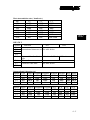
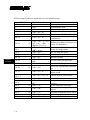
Table of Contents
GENERAL DESCRIPTION · · · · · · · · · · · · · · · · · · · 1
- 1
OVERVIEW · · · · · · · · · · · · · · · · · · · · · · · · · · · · 1 - 1
MODEL NUMBERS · · · · · · · · · · · · · · · · · · · · · · · · 1 - 1
FEATURES · · · · · · · · · · · · · · · · · · · · · · · · · · · · 1 - 2
INSTALLATION · · · · · · · · · · · · · · · · · · · · · · · · · ·
2 - 1
UNPACKING CONTENTS · · · · · · · · · · · · · · · · · · · · 2 - 1
BASIC MOUNTING · · · · · · · · · · · · · · · · · · · · · · · · 2 - 1
FOR POSiFLEX PST POS SYSTEM · · · · · · · · · · · · · 2 - 1
FOR OTHER SYSTEM · · · · · · · · · · · · · · · · · · · 2 - 3
CABLE CONNECTIONS · · · · · · · · · · · · · · · · · · 2 - 3
LOADING RIBBON CARTRIDGE · · · · · · · · · · · · · · · · 2 - 4
LOADING PAPER · · · · · · · · · · · · · · · · · · · · · · · · 2 - 6
REMOVING THE ROLL PAPER · · · · · · · · · · · · · · 2 - 8
OPERATION GUIDE · · · · · · · · · · · · · · · · · · · · · · · 3
- 1
FRONT PANEL · · · · · · · · · · · · · · · · · · · · · · · · · · 3 - 1
SELF PRINT TEST · · · · · · · · · · · · · · · · · · · · · · · · 3 - 2
HEXADECIMAL DUMP MODE · · · · · · · · · · · · · · · · · 3 - 4
CLEAR PRINT BUFFER · · · · · · · · · · · · · · · · · · · · · 3 - 4
MICRO FEED · · · · · · · · · · · · · · · · · · · · · · · · · · · 3 - 4
VALIDATION PRINTING · · · · · · · · · · · · · · · · · · · · 3 - 4
i
TM
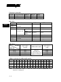
OPERATION METHOD · · · · · · · · · · · · · · · · · · · 3 - 5
PRINTING FORMAT · · · · · · · · · · · · · · · · · · · · 3 - 6
DATA FORMAT · · · · · · · · · · · · · · · · · · · · · · 3 - 6
PAPER FORMAT · · · · · · · · · · · · · · · · · · · · · · 3 - 6
THER CONSIDERATIONS · · · · · · · · · · · · · · · · · 3 - 6
PERIPHERAL UNIT DRIVE CIRCUIT · · · · · · · · · · · · · · 3 - 7
TECHNICAL BACKGROUND
················ 4 - 1
BLOCK DIAGRAM · · · · · · · · · · · · · · · · · · · · · · · · 4 - 1
CIRCUITRY LAYOUT & CONNECTORS · · · · · · · · · · · · 4 - 2
JUMPERS & SWITCHES · · · · · · · · · · · · · · · · · · · · · 4 - 4
JUMPER SETTING · · · · · · · · · · · · · · · · · · · · · 4 - 4
SERIAL INTERFACE SWITCH · · · · · · · · · · · · · · · 4 - 4
PARALLEL INTERFACE SWITCH · · · · · · · · · · · · · 4 - 7
DATA STRUCTURE IN SERIAL INTERFACE · · · · · · · · · · 4 - 9
DTR MODE · · · · · · · · · · · · · · · · · · · · · · · · · 4 - 9
STATUS · · · · · · · · · · · · · · · · · · · · · · · 4 - 9
PAPER OUT · · · · · · · · · · · · · · · · · · · · · 4 - 9
MECHANICAL ERROR · · · · · · · · · · · · · · · · 4 - 10
FRAMING ERROR · · · · · · · · · · · · · · · · · · 4 - 10
CASH DRAWER OPEN DETECTION SWITCH · · · · · 4 - 10
X-ON/X-OFF MODE · · · · · · · · · · · · · · · · · · · · 4 - 10
STATUS · · · · · · · · · · · · · · · · · · · · · · · 4 - 11
PAPER OUT · · · · · · · · · · · · · · · · · · · · · 4 - 11
MECHANICAL ERROR · · · · · · · · · · · · · · · · 4 - 11
FRAMING ERROR · · · · · · · · · · · · · · · · · · 4 - 12
CASH DRAWER OPEN DETECTION SWITCH · · · · · 4 - 12
STX-ETX MODE · · · · · · · · · · · · · · · · · · · · · · 4 - 12
ii
TM
MAIN SPECIFICATION · · · · · · · · · · · · · · · · · · · · ·
5 - 1
INTERFACE · · · · · · · · · · · · · · · · · · · · · · · · · · · 5 - 1
PARALLEL INTERFACE · · · · · · · · · · · · · · · · · · 5 - 1
SERIAL INTERFACE · · · · · · · · · · · · · · · · · · · · 5 - 3
PERIPHERAL UNIT DRIVE · · · · · · · · · · · · · · · · 5 - 3
POWER SUPPLY · · · · · · · · · · · · · · · · · · · · · · · · · 5 - 4
OPTION LIST · · · · · · · · · · · · · · · · · · · · · · · · · · · 5 - 4
FONT MATRICES · · · · · · · · · · · · · · · · · · · · · · · · 5 - 4
COMMANDS · · · · · · · · · · · · · · · · · · · · · · · · · · · 5 - 6
FRICTION TYPE · · · · · · · · · · · · · · · · · · · · · · 5 - 6
SPROCKET TYPE · · · · · · · · · · · · · · · · · · · · · 5 - 6
EXTERNAL DIMENSIONS · · · · · · · · · · · · · · · · · · · · 5 - 6
FRICTION TYPE · · · · · · · · · · · · · · · · · · · · · · 5 - 6
SPROCKET TYPE · · · · · · · · · · · · · · · · · · · · · 5 - 6
WEIGHT · · · · · · · · · · · · · · · · · · · · · · · · · · · · · 5 - 6
FRICTION TYPE · · · · · · · · · · · · · · · · · · · · · · 5 - 6
OPERATING ENVIRONMENT · · · · · · · · · · · · · · · · · · 5 - 6
TEMPERATURE · · · · · · · · · · · · · · · · · · · · · · 5 - 6
HUMIDITY · · · · · · · · · · · · · · · · · · · · · · · · · 5 - 6
STORAGE ENVIRONMENT · · · · · · · · · · · · · · · · · · · 5 - 6
TEMPERATURE · · · · · · · · · · · · · · · · · · · · · · 5 - 6
HUMIDITY · · · · · · · · · · · · · · · · · · · · · · · · · 5 - 6
iii
TM
MAINTENANCE · · · · · · · · · · · · · · · · · · · · · · · · · ·
6 - 1
CLEANING · · · · · · · · · · · · · · · · · · · · · · · · · · · · 6 - 1
PAPER JAM · · · · · · · · · · · · · · · · · · · · · · · · · · · 6 - 1
TROUBLE SHOOTING · · · · · · · · · · · · · · · · · · · · · · 6 - 2
CONTROL CODES · · · · · · · · · · · · · · · · · · · · · · · · 7
- 1
STAR COMPATIBLE MODE · · · · · · · · · · · · · · · · · · · 7 - 1
CONTROL CODES FOR CHARACTER SETTING · · · · · · 7 - 1
CONTROL CODES FOR LINE SPACING · · · · · · · · · · 7 - 2
CONTROL CODES FOR PAGE LAYOUT · · · · · · · · · · 7 - 2
CONTROL CODES FOR GRAPHICS PRINTING · · · · · · · 7 - 3
CONTROL CODES FOR DOWNLOAD CHARACTERS · · · 7 - 3
CONTROL CODES FOR PERIPHERAL UNITS · · · · · · · 7 - 4
OTHER CONTROL CODES · · · · · · · · · · · · · · · · · 7 - 4
EPSON EMULATION MODE · · · · · · · · · · · · · · · · · · · 7 - 4
BASIC REFERENCE · · · · · · · · · · · · · · · · · · · · 7 - 4
HARDWARE MODIFICATION REQUIRED · · · · · · · · · 7 - 4
REFERENCE EPSON MODELS EMULATED · · · · · · · · 7 - 5
CHARACTER SIZE/FONT MATRICES · · · · · · · · · · · 7 - 5
UNSUPPORTED CONTROL CODES · · · · · · · · · · · · 7 - 5
SUPPORTED CONTROL CODES · · · · · · · · · · · · · · 7 - 5
iv
TM
APPENDIX A
STAR COMPATIBLE MODE COMMAND DETAIL · · A
- 1
APPENDIX B
FONT TABLES
··························B - 1
U.S.A. & EUROPE · · · · · · · · · · · · · · · · · · · · · · · · · B - 1
IBM CHARACTER SET #1 · · · · · · · · · · · · · · · · · · · · B - 3
IBM CHARACTER SET #2 · · · · · · · · · · · · · · · · · · · · B - 5
JAPAN · · · · · · · · · · · · · · · · · · · · · · · · · · · · · · B - 7
INTERNATIONAL CHARACTER SET · · · · · · · · · · · · · · B - 9
APPENDIX C
Q&A
v
································· C - 1
TM
CHAP. 1
GENER…
GENERAL DESCRIPTION
OVERVIEW
The PP3000 series POS printer is a stream-lined low profile 40 column 9
pin dot matrix printer designed to fit the PST system perfectly well and also for
other POS printing applications. This printer utilizes a mechanism supplied from
Star Micronics Co., LTD., and is compatible to the SP312 printers of Star
Micronics in every aspects (with validation print). An optional version of this
printer to simulate the EPSON command set is also available.
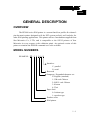
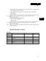
MODEL NUMBERS
EXAMPLE: PP - 3 0 0 0 S
Interface:
C: parallel
S: serial
Reserved
Language / Expanded character set:
0: English (standard)
1: GB-code Chinese
2: BIG-5 code Chinese
3: Korean
4: Thai
Paper feed:
0: friction type
1: sprocket type
Product series
POS printer
1-1
TM
CHAP. 1
GENER…
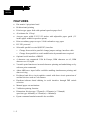
FEATURES
•
Dot matrix 9 pin printer head
•
Bi-directional printing
•
Friction type paper feed with optional sprocket paper feed
•
40 columns for 15.4cpi
•
Accepts paper width 2.25/3/3.25 inches with adjustable paper guide (3.5
inches paper width for sprocket option)
•
Print on ordinary paper or up to 3-fold carbonless copy paper
•
DC 24V powered
•
Selectable parallel or serial (RS232C) interface
∗
Change from serial to parallel: change jumper settings; interface cable.
∗
Change from parallel to serial: modification by manufacturer required.
•
Optional serial interface of RS422
•
4 character sets supported: USA & Europe, IBM character set #1, IBM
character set #2, Japan
•
Versatile print function as inverted character printing and underlining set by
software print commands
•
About 4KB max. input buffer available enabling simultaneous printing and
data receiving
•
Peripheral unit drive circuit enables control with short circuit protection of
external devices such as Cash Drawer
•
Hardware/software hand shaking in serial interface through DIP switch
selection
•
Manual paper cut mechanism
•
Validation printing function
•
Dimension: friction type: 273mm(l) x 125mm(w) x 174mm(h)
sprocket type: 400mm(l) x 155mm(w) x 180mm(h)
•
Epson command emulation model also available
1-2
TM
CHAP. 2
INSTA…
INSTALLATION
UNPACKING CONTENTS
•
•
•
•
•
•
•
•
•
•
•
•
The printer
Test ribbon cartridge
Roll paper shaft
Spacer for 3” paper roll (2 ea.)
Spacer for 2.25” paper roll (2 ea.)
E -ring (2 ea.)
Test paper roll
Springy hook plate (mounted)
Rear hook
Screws to hold springy hook plate (mounted) and rear hook
Manual
Power adapter with power cord (option)
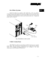
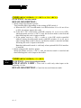
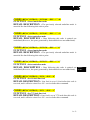
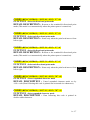
BASIC MOUNTING
For POSiFLEX PST POS System
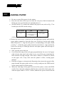
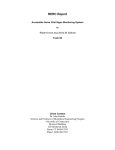
First install the springy hook plate and rear hook onto the metal bottom
plate of the POS printer. Unscrew and re-install the springy hook plate in the
way that the two springy hooks come out of the front edge of the metal bottom
plate (they were pointing inward when shipped). Install the rear hook with its
middle hook lock into the metal bottom plate first and screw the rear hook to the
metal bottom plate (ref. Fig. 1). Connect the power cable and the printer cable
(CCBLA-191 for serial interfaced printer or CCBLA-192 for parallel interfaced
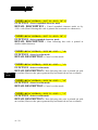
printer) in the way illustrated in the section of “CABLE CONNECTIONS”. Push
open the battery cover of PST system and pass the cables through the opening
beside the battery cover on the PST POS system and close the battery cover
2-1
TM
CHAP. 2
INSTA…
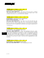
again. (ref. Fig. 2, the example uses parallel interface) Aim the rear hook to the
rectangular opening on the printer platform and push the printer down and
forward till the two springy hooks click into the openings between the
programmable keyboard and the printer platform in PST system. Consolidate the
cables and connect them to the appropriate ports inside the back cover of PST
system.
Hook lock on
rear hook
Openings for
hooks
L3 L4
L2
L1
L0 LP
Rear hook
Springy hooks
Springy hook plate
Fig. 1 Mounting printer to PST
Battery over
Routing cables
through this opening
Power cable
Printer cable
(serial or parallel)
Fig. 2 Cable routing in PST application
2-2
TM
CHAP. 2
INSTA…
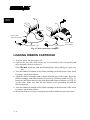
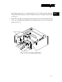
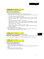
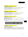
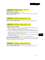
For Other System
Install the printer on a stand or table which has a flat, even surface.
Connect the power cord supplied for the power adapter (ref. Fig. 3) which varies
according to destination region to a power outlet which is not used for any other
electrical noise generating devices such as an electrical motor, etc.. Connect the
printer cable as required.
Power
adapter
Printer cable
(serial or parallel)
Fig. 3 Installation to other system
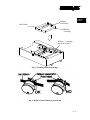
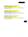
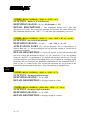
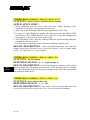
Cable Connections
The PP3000 can either be powered by the PST system or by a separate
power adapter. The serial interface and parallel interface apply different interface
cables. The following drawings demonstrate two examples of the cable
connections to the POS printer PP3000 series.
2-3
TM
CHAP. 2
INSTA…
25PF
Power cable
from PST system
9PM
9PF
25PM
Parallel interface cable
Serial interface
cable
Power cable
from adapter
Fig. 4 Cable connection examples
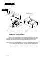
LOADING RIBBON CARTRIDGE
• Turn the power for the printer off.
• Squeeze the two side walls of the top cover inward at the rear portion and
raise and pull it back to remove it.
Note: Do not touch the print head immediately after printing as it gets very
hot.
• Turn the ribbon feed knob of the ribbon cartridge in the direction of the arrow
to remove slack in the ribbon.
• Align the ribbon cartridge guide with the notched part of the frame. Insert the
ribbon cartridge from that position till you hear a locking sound (ref. Fig. 5).
Insert the ink ribbon between the print head and ribbon separator (ref. Fig. 6).
At this time, make sure that the ink ribbon is not protruding beyond the
ribbon separator.
• Turn the ribbon feed knob of the ribbon cartridge in the direction of the arrow
to remove slack in the ribbon.
• Mount the front cover by reversing the procedure outlined in previous steps.
2-4
TM
CHAP. 2
INSTA…
Ribbon
feed knob
Ink ribbon
Ribbon
cartridge
Ribbon cartridge
inserted in place
Fig. 5 Loading ribbon cartridge
Fig. 6 Detail of ink ribbon at print head
2-5
TM
CHAP. 2
INSTA…
LOADING PAPER
•
•
•
Be sure to turn off the power for the printer.
Press the two sides of the top cover near the rear part a little bit inward and
lift the top cover up from the rear end and remove it.
Set DIP switch 2-5 to match the width of the paper to use (refer to Fig. 17 on
board layout for DIP switch setting).
DIP switch
ON
OFF
3.25 inches
2-5
3.0 inches
2.25 inches
(All the switches in the DIP switch array are factory preset to ON)
• Release the lock levers of both the left and right paper guides and push the
paper guides outward to show the three sets of grooves on the paper guide
shaft. Insert the E - rings into the grooves corresponding to the paper width
(ref. Fig. 7 ). Push the paper guides inward to touch the E - rings and fix the
lock levers leaving a 0.5mm gap between each paper guide and each edge of
the paper to feed.
• Now, turn the power back on.
• Cut off the front edge of the roll paper perpendicularly. In case of roll paper
with its front edge stuck with a label or so, cut off the part containing the
label and then cut edge straight. If the label’s adhesive is allowed to remain
on the paper roll, it may stick onto the printer’s rollers, causing paper
misfeed.
• Hold the roll paper as shown in the illustration, then insert the top end of the
paper beneath the paper guide as far as it will go and press the FEED switch
on the control panel to feed the paper.
• When the front edge of the paper feeds out of the printer, release the FEED
switch. Next, insert the roll paper shaft into the center hole of the paper roll,
when the paper width is 2.25 or 3 inches, add the two spacers from each end
2-6
TM
•
(the thinner spacer for 3” and the thicker for 2.25” both with the flat side
facing inward) and put the whole assembly onto the roll paper shaft holder
(ref. Fig. 8).
Insert the top edge of the paper into the paper cut slot, then mount the top
cover by reversing the procedure for removing the top cover in previous
steps (ref. Fig. 9).
Lock lever (right)
2.25"
3.0"
3.25"
Paper guide (left)
Fig. 7 Grooves on paper guide shaft
2-7
CHAP. 2
INSTA…
TM
CHAP. 2
INSTA…
(3
.0
"
SP
AC
(2
ER
.2
5"
)
SP
AC
ER
)
Fig. 8 Putting spacer to roll paper shaft
Insert paper through
the paper cut slot
behind the tear bar
Fig. 9 Finish paper loading
Removing The Roll Paper
Remove the top cover then cut off the paper near the rear of the paper
guide and press the FEED switch to feed out the paper remaining in the unit.
When the paper runs out, a buzzer will sound 4 times per cycle for 2 cycles.
Note 1. Remove the paper remaining in the printer by pressing the FEED switch
(If you remove the paper by hand, the paper could be wrinkled or slip
and cause a paper jam).
2. When the paper end mark appears on the paper, replace the roll paper
before it runs out.
2-8
TM
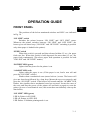
OPERATION GUIDE
FRONT PANEL
CHAP. 3
OPERA…
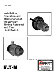
The positions of the below mentioned switches and LED’s are indicated
in Fig. 10.
“ON LINE” switch
Switches the printer between “ON LINE” and “OFF LINE” status.
Whenever the printer switches between “ON LINE” and “OFF LINE”, the
buzzer gives one short beep (“ON LINE” and “OFF LINE” switching is possible
only when paper is loaded in the printer).
“FEED” switch
When this switch is pressed and then released within 0.5 sec., the paper
feeds one line. When this switch is held depressed for more than 0.5 sec., the
paper feeds continuously (The above paper feed operation is possible for both
“ON LINE” and “OFF LINE” modes).
“POWER” LED (green)
Lights when the power for the printer is on.
“ALARM” LED (red)
Lights when the paper is out. (If the paper is out, load a new roll and
press the “ON LINE” switch.)
Flashes when a mechanical error (motor lock etc.) occurs. The buzzer will
give one short beep followed by a long beep. Mount the top cover properly and
press the “ON LINE” switch. If the buzzer still sounds and the “ALARM” LED
flashes, this signifies that a mechanical error has occurred. Locate the cause of
the error and turn the power of the printer off and back on again to reset the
printer (In case of a mechanical error, this restart does not definitely clear up the
data buffer).
“ON LINE” LED (green)
LED lit: Printer is ON LINE
LED off: Printer is OFF LINE
LED flashes: Validation printing mode is set.
3-1
TM
When all LEDs light up simultaneously and the buzzer sounds
continuously, a CPU error has occurred. In case of a CPU error, turn off the
power then turn it on again. When turning off the power, the data will be
cleared.
CHAP. 3
OPERA…
Power LED
(Green)
On-line LED
(Green)
On-line
switch
Feed
switch
Alarm LED
(Red)
Power
On-off
switch
Fig. 10 Locations of switches and LED’s
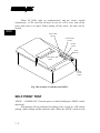
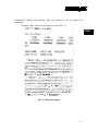
SELF PRINT TEST
“FEED” + “POWER ON” (Turn the power on while holding the “FEED” switch
depressed)
Self-printing will be performed according to the version no., DIP switch
settings, mode settings and the character order. When the “FEED” switch is held
3-2
TM
continuously during self printing, only the characters will be printed out
repeatedly.
A sample of the output of self print is given in Fig. 11.
CHAP. 3
OPERA…
Fig. 11 Self print sample
3-3
TM
HEXADECIMAL DUMP MODE
CHAP. 3
OPERA…
“ON LINE” + “POWER ON” (Turn the power on while holding the “ON LINE”
switch depressed)
Each of the signals sent from the computer to the printer will be printed
out in hexadecimal code. This function allows you to check if a control code
sent to the printer by the program being used is correct or not. The buzzer will
sound once to indicate the printer is in hexadecimal dump mode. After the
program has been run, the last line buffer should be flushed by pressing the “ON
LINE” switch. To turn off the mode, it is necessary to turn off the printer
completely.
CLEAR PRINT BUFFER
“FEED” + “ON LINE” + “POWER ON” (Turn the power on while holding both
the “FEED” and “ON LINE” switches depressed)
This operation clears the printer buffer (The buzzer gives two short
beeps). When the printer power is shut off, the data content could degenerate
and become unusable. For this reason, when the printer power is turned off and
there are some left-over in the data buffer or if there is any scramble up in data
receiving, perform the above operation to clear the data in the data buffer. Note
that the data in the buffer can also be cleared by control code <CAN>.
MICRO FEED
“ON LINE” + “FEED” (Press the “FEED” switch while holding the “ON LINE”
switch depressed when the printer is “OFF LINE”)
As a result of this mode, the paper will feed in very small increments.
VALIDATION PRINTING
This printer can print one line of validation printing as described below.
3-4
TM
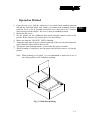
Operation Method
1. Open the top cover, pull the adjust lever one notch from standard position
toward the operation panel side. When you cannot find standard position,
push the lever as far as possible toward the rear, then pull it by 2 notches
after having pressed it down. The lever is now in standard position.
2. Mount the top cover.
3. Set the printer for the validation print mode through control codes to the
printer. In this instance, the buzzer gives two short beeps.
4. Make sure that the “ON LINE” LED is flashing.
5. Align the right edge of paper with the right end of the tear bar then insert the
paper from the top in front of the tear bar.
6. The printer starts printing about 1 second after the paper is loaded.
7. When printing is completed, pull the paper upward and remove it from the
printer.
Note: When printing a roll paper, it is recommended to adjust the lever at
the same position as for validation printing.
Fig. 12 Validation printing
3-5
CHAP. 3
OPERA…
TM
Printing Format
CHAP. 3
OPERA…
Prints one line in 7 x 9 font normal printing.
32 columns (from the 5th to the 36th column)
Even if the setting for paper width is changed by the DIP switch, the 32-column
format will not change.
Data Format
<GS> data <LF>
Paper Format
Fig. 13 Dimensional limits of Validation print
Other Considerations
• The FEED and ON LINE switches will not operate normally during
validation printing.
• When the printer receives an immediate execution command for peripheral
units during validation printing, it executes the command when the validation
print mode is canceled.
• Modes in effect before the validation printing (such as emphasized printing,
inverted printing, expanded printing and underlining) are invalid during
validation printing. But these become valid again after validation printing.
3-6
TM
• Data received before a <GS> code is printed out when the printer receives the
<GS> code.
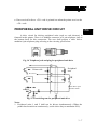
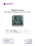
PERIPHERAL UNIT DRIVE CIRCUIT
CHAP. 3
OPERA…
A drive circuit for driving peripheral units (such as cash drawers) is
featured in this printer. There is a modular connector of 6 pin telephone jack at
the bottom back for this connection. The user shall prepare a cable with a
modular 6 pin telephone plug referring to the circuitry given below.
Fig. 14 Telephone jack and plug for peripheral unit drive
Printer side
Peripheral
unit
DC source
Cash drawer open
detection switch
Fig. 15 Circuit diagram for peripheral unit drive
Notes:
1. Peripheral units 1 and 2 shall not be driven simultaneously (When the
printer has been driven continuously, set the drive duty to maximum 20%).
3-7
TM
CHAP. 3
OPERA…
2. The status of the cash drawer open detection switch is interpreted as bit 7 of
the printer status data (Refer to Data Structure in Serial Interface).
3. Recommended resistance values of coils L1 and L2 are minimum 10Ω.
4. The pin assignment of this connector is compatible to Star SP-312 and SP320 series.
5. The cable CCBLA-180 is used for this connector to connect to POSiFLEX
cash drawer CR3100 or CR3200.
3-8
TM
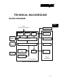
TECHNICAL BACKGROUND
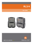
BLOCK DIAGRAM
CHAP. 4
TECHN…
Data
(from host computer)
Parallel
interface
Control
panel
board
Serial
interface
Driver
Print head
Gate array
Carriage motor
CPU
Detectors
Paper
out
detector
24 VDC
5 VDC
Peripheral unit
EPROM
32KB
Driver
RAM 8KB
Control board
Paper feed
motor
Printer
mechanism
Fig. 16 Circuit block diagram
4-1
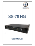
TM
CIRCUITRY LAYOUT & CONNECTORS
CN3
CN2
U1
CN1
U2
U5
JP1 JP2
SP232ACP
1
3
U3
TMP90C041AF
JP3 JP4
EDG
3
CN4
U6
1
CHAP. 4
TECHN…
8
7
6
5
4
CN5
3
2
SW1
ON
1
1
2
5
6
JP5
JP8
JP6
JP10
M27C512
CN6
U8
JP12
3
EDG
8
1
7
JP7
JP9
JP11
JP13
6
CN7
5
CN9
4
3
2
SW2
CN8
ON
1
EDG
8
B303 6DAHG
7
6
U11
5
4
3
SW3
2
ON
1
EDG
4
1
3
JP14
3
CN11
2
ON
1
SW4
JP15
U16
PST-PRT001A-TJ
CN10
BZ1
BAT1
Fig. 17 Board layout
CN1 : Reserved
CN2 : Control panel connector
This CN2 connector connects the control panel board through cable CCBLA189.
CN3 : Power switch connector
This CN3 is connected to cable CCBLA-188 to connect to the printer power
switch.
CN4 : Serial interface connector
This connector is used to connect the host computer by RS-232C or RS-422A.
The MAX232A has to be installed in U3 to use RS-232 interface and MC3451
4-2
TM
has to be installed in U2 to use RS-422A interface. The details are described in
the table below.
U3
U2
RS-232C
Install MAX232A NOT installed
RS-422A
NOT installed
Install MC3451
The cable used in RS-232C application is CCBLA-191 (a DB 9 male to DB 9
female cable).
CHAP. 4
TECHN…
CN5 : Reserved
CN6 : Peripheral drive connector
This connector uses cable CCBLA-180 to drive peripheral unit such as cash
drawer.
CN7 : Paper detector connector
This connector uses cable CCBLA-190 to detect whether paper is set or
out .When the paper is out, the buzzer will sound and the alarm LED will be
flashing to remind the user.
CN8 : Printer control connector
This connector is connected to printer mechanism through a nineteen pin flexcable, to drive the carriage motor.
CN9 : Printer power input connector
This is the power input connector, and the input voltage is 24V DC.
CN10 : Parallel interface connector
This connector uses cable CCBLA-077-2 (DB 25 male to DB 25 female cable)
to connect to the host computer by parallel interface or CCBLA-192 to connect
to parallel port (LPT 1) of POSiFLEX PST system.
CN11 : Print head drive connector
This connector connects to printer mechanism through a fourteen pin flex-cable
to drive the mechanism printer head.
BZ1 : Printer buzzer
The printer buzzer will sound when printers error occurs.
4-3
TM
U6&U8 : Font and BIOS socket
This socket is used to install BIOS and character font. Each type of printer
requires different BIOS and character font. For example, the BIOS for friction
type mechanism and the BIOS for sprocket type mechanism are different.
JUMPERS & SWITCHES
CHAP. 4
TECHN…
Jumper Setting (Interface Select)
INTERFACE
JP3 JP4
JP6-JP13
JP14
JP15
OPEN
1-2 SHORT 1-2 SHORT SHORT
SERIAL PORT
PARALLEL PORT 2-3 SHORT 2-3 SHORT 2-3 SHORT OPEN
When using either interface, the connector of the other interface must be
disconnected. DIP SW3 and DIP SW4 have to be turned off when parallel
interface is used.
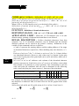
Serial Interface Switch
DIP - SW1
Switch
Function
1-1
Data transmission
1-2
Rate (baud rate )
1-3
1-4
Not used
1-5
Hand shake
1-6
Data bit
1-7
Parity check
1-8
Parity selection
4-4
ON
OFF
See next table
DTR mode
8-bit data
No parity check
Odd parity
X-ON/X-OFF mode
7-bit data
Parity check
Even parity
TM
Data transmission rate ( baud rate )
bps
1-1
1-2
150
OFF
OFF
300
OFF
OFF
600
OFF
ON
1200
OFF
ON
2400
ON
OFF
4800
ON
OFF
9600
ON
ON
1-3
OFF
ON
OFF
ON
OFF
ON
ON/ OFF
CHAP. 4
TECHN…
DIP-SW 2
Switch
Function
ON
OFF
2-1
2-2
International character set See table below
2-3
2-4
2-5
Paper width for friction 3.0 inch or 3.25 inch 2.25 inch
type
2-6
Not used
2-7
Character code table
See table below
2-8
International character set
Switch USA France Germany England Denmark Sweden Italy Spain
2-1
ON
ON
ON
ON
OFF
OFF OFF OFF
2-2
ON
ON
OFF
OFF
ON
ON
OFF OFF
2-3
ON
OFF
ON
OFF
ON
OFF
ON OFF
2-4
ON
ON
ON
ON
ON
ON
ON ON
Switch Japan Norway DenmarkII Croatian N.A.
2-1
ON
ON
ON
ON
OFF
2-2
ON
ON
OFF
OFF
ON
2-3
ON
OFF
ON
OFF
ON
2-4
OFF
OFF
OFF
OFF
OFF
N.A.
OFF
ON
OFF
OFF
N.A.
OFF
OFF
ON
OFF
N.A.
OFF
OFF
OFF
OFF
4-5
TM
Character code table
Switch U.S.A. & Europe
2-7
ON
2-8
ON
CHAP. 4
TECHN…
DIP-SW3
Switch
3-1
3-2
3-3
3-4
IBM #1
ON
OFF
IBM #2
OFF
ON
Function
ON
Not used
Control code CR
When turning DC1,DC3
the power on. mode
Addressable
mode
Setting the paper feed length
Setting the buffer size
Not used
Paper out detection function
3-5
3-6
3-7
3-8
Japan
OFF
OFF
OFF
Invalid
Select
Valid
Deselect
Deselect
Select
1/6 - inch
4 K-bytes
1/8 - inch
256 bytes
Valid
Invalid
DIP-SW 4
MODE
DIP SW
4-1
4-2
4-3
4-4
DC1, DC3
invalid
Addressable mode
DC1, DC3
valid
ON
ON
ON
ON
Refer to
next table for
switch setting and
address selection
OFF
OFF
OFF
OFF
Address selection for addressable mode:
SW #1 #2 #3 #4 #5 #6 #7 #8 #9
4 - 1 OFF ON OFF ON OFF ON OFF ON OFF
4 - 2 ON OFF OFF ON ON OFF OFF ON ON
4 - 3 ON ON ON OFF OFF OFF OFF ON ON
4 - 4 ON ON ON ON ON ON ON OFF OFF
Note: The addressable mode is valid only when an
interface is mounted.
4-6
#10 #11 #12 #13 #14
ON OFF ON OFF ON
OFF OFF ON ON OFF
ON ON OFF OFF OFF
OFF OFF OFF OFF OFF
optional RS-422A serial
TM
a) When DIP SW4-1 through 4-4 are all ON (DC1/DC3 invalid mode)
DC1 and DC3 codes are invalid.
b) When DIP SW4-1 through 4-4 are OFF (DC1/DC3 valid mode)
DC1: Select
DC3: Deselect
When the printer receives the DC3 code, it throws away data until it
receives the DC1 code. (all the data between the DC3 and DC1 code)
DTR is always ready.
c) Other settings (addressable mode)
DC1 n: selects n (address)
DC3: Deselect
When the printer receives the DC3 code, it throws away data until it
receives the DC1 n code (with the n matching the printer’s own address).
DTR is always ready.
Note : DIP sw1-4 select the select/deselect state for the printer when the power
is first switched on.
Parallel Interface Switch
DIP-SW1
Switch
1-1
1-2
1-3
1-4
1-5
1-6
1-7
1-8
Function
Not used
Control code CR
Not used
Setting the paper feed length
Setting the buffer size
Not used
Paper out detection function
ON
OFF
Invalid
Valid
1/6 - inch
4 K-bytes
1/8 - inch
256 bytes
Valid
Invalid
4-7
CHAP. 4
TECHN…
TM
CHAP. 4
TECHN…
DIP-SW 2
Switch
Function
2-1
2-2
International character set
2-3
2-4
2-5
Not used
2-6
2-7
Character code table
2-8
ON
OFF
See table below
See table below
International character set
Switch USA France Germany England Denmark Sweden
2-1
ON
ON
ON
ON
OFF
OFF
2-2
ON
ON
OFF
OFF
ON
ON
2-3
ON
OFF
ON
OFF
ON
OFF
2-4
ON
ON
ON
ON
ON
ON
Switch Japan Norway DenmarkII Croatian
2-1
ON
ON
ON
ON
2-2
ON
ON
OFF
OFF
2-3
ON
OFF
ON
OFF
2-4
OFF OFF
OFF
OFF
Character code table
Switch U.S.A. & Europe IBM #1
2-7
ON
ON
2-8
ON
OFF
4-8
IBM #2
OFF
ON
N.A.
OFF
ON
ON
OFF
N.A.
OFF
ON
OFF
OFF
Japan
OFF
OFF
Italy
OFF
OFF
ON
ON
N.A.
OFF
OFF
ON
OFF
Spain
OFF
OFF
OFF
ON
N.A.
OFF
OFF
OFF
OFF
TM
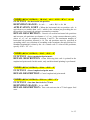
DATA STRUCTURE IN SERIAL INTERFACE
DTR Mode
This mode is accessed when the DIP switch 1-5 is ON. Signals are
controlled using the DTR line as BUSY flag. If a printer errors do not occur after
the power is turned on, the DTR signal line changes to “SPACE”. When the host
computer confirms that the DTR signal line is set to “SPACE”, the host
computer sends the data text via the RXD signal line to the printer. Also, the
printer will set the DTR signal line to “MARK” when the empty space in the
data buffer is below 256 bytes. After the host computer detects that the DTR
signal line is at “MARK”, transmission of the data text is stopped. In this
instance, data can still be received up until the data buffer becomes completely
full. When the empty space in the data buffer is increased following printing
(when the data in the data buffer is reduced to 256 bytes or less), the printer sets
the DTR signal line to “SPACE”.
Status
Bit position
b0
b1
b2
b3
b4
b5
b6
b7
Definition
Vertical parity error
Framing error
Mechanical error
Paper empty
Constantly set at “0”
Buffer empty
Buffer overflow
Cash drawer open detection
switch high level
Level
1:error
1:error
1:error
1:empty
0
1:empty
1:overflow
switch is set to ON
Paper out
When the “paper out” detector senses the end of the paper, the printer
stops printing after printing a maximum of two lines or on feeding the paper.
Immediately after a “paper out” condition is detected, the printer sets to “OFF
LINE” and the DTR changes to “MARK”. To reset the printer after a “paper
4-9
CHAP. 4
TECHN…
TM
out”, load paper into the printer and press the “ON LINE” switch to set the
printer to “ON LINE”.
Mechanical error
CHAP. 4
TECHN…
Mechanical errors are detected when the motor locks or else and the unit
will not print. Immediately after a mechanical error occurs, the printer sets the
DTR to “MARK” and then sets the printer to “OFF LINE”. To cancel a
mechanical error, close the front cover properly and press the “ON LINE”
switch. If the buzzer sounds and the “ALARM” LED flashes at this time, then
locate the cause of the error and turn the power for the printer off and back on
again to reset the printer.
Framing error
A framing error occurs when “SPACE” is detected at the stop bit. When a
framing error or a vertical parity error occurs for the data which is received, the
printer prints out a “?” mark to indicate that the error occurred.
Cash drawer open detection switch
When pin 6 of the peripheral unit drive circuit connector is set “HIGH”,
status bit 7 becomes “1”.
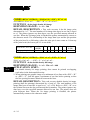
X-ON/X-OFF Mode
This mode is accessed when the DIP switch 1-5 is OFF. If printer errors
do not occur after the power is turned on, the printer outputs an X-ON (DC1 by
control code; 11H by hexadecimal data) signal on the TXD signal line of the
printer which sends it to the host computer. When the host computer receives the
X-ON signal, the host computer transmits the data to the RXD signal line of the
printer. If data text is not sent from the host computer (even after transmitting
the X-ON signal to the host computer), the printer outputs an X-ON signal at 3
second intervals until the printer receives data. The printer starts outputting an
X-OFF (DC3, 13H) signal when the empty space in the buffer reduces below
256 bytes. When the host computer receives the X-OFF signal, it halts output of
data (however, the printer can continue receiving data until the buffer becomes
4 - 10
TM
completely full). Output of the X-ON signal is resumed when the data in the
buffer is printed out and drops to below 256 bytes.
Status
Bit position
b0
b1
b2
b3
b4
b5
b6
b7
Definition
Vertical parity error
Framing error
Mechanical error
Paper empty
Constantly set at “0”
Buffer empty
Buffer overflow
Cash drawer open detection
switch high level
Level
1:error
1:error
1:error
1:empty
0
1:empty
1:overflow
CHAP. 4
TECHN…
switch is set to ON
Paper out
When the “paper out” detector senses the end of the paper, the printer
stops printing after printing a maximum of two more lines or on feeding the
paper. The printer will set the DTR to “MARK” and set the printer to OFF LINE
five seconds after a “paper out” condition is detected. To reset the printer after a
“paper out”, load a new roll of paper into the printer and press the ON LINE
switch to set the printer ON LINE.
Mechanical error
Mechanical error occurs when the motor locks or else and printing stops.
After the error occurs, the printer outputs an X-OFF signal and stops printing.
The printer sets the DTR signal to “MARK” and sets to “OFF LINE” five
seconds after a mechanical error occurs. To reset the printer after a mechanical
error occurs, close the top cover properly and press the “ON LINE” switch. If a
buzzer sounds and the “ALARM” LED flashes at this point, locate the cause of
the error and turn the power off and then back on to reset the printer.
4 - 11
TM
Framing error
A framing error occurs when “SPACE” is detected at the stop bit. When a
framing error or a vertical parity error occurs for the data which is received, the
printer prints out a “?” mark to indicate that the error occurred.
Cash drawer open detection switch
CHAP. 4
TECHN…
When pin 6 of the peripheral unit drive circuit connector is set at
“HIGH”, status bit 7 becomes “1”.
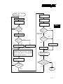
STX-ETX Mode
This mode is accessed from whichever DTR mode or X-ON/X-OFF
mode. To set this mode, the data buffer must be empty. The host computer sends
an “ENQ” code to the printer and acknowledges the printer status. Then, the host
computer checks if the printer buffer is empty. After the host computer detects
that the buffer is empty, a STX code and data are transmitted. After 1 block of
data is transmitted, the host computer sends an ENQ code to the printer and then
receives the printer status and check byte (horizontal parity for the printer). At
this point, the host computer performs a status and horizontal parity check.
When the host computer determines that there was no error, it transmits an ETX
code which serves as end text code. After the printer receives the ETX code, data
in the data buffer is printed out. If an error occurs, a CAN code is transmitted by
the host computer (In this instance, the data which was previously sent to the
buffer is cleared, thus, the host computer must retransmit the same data to the
printer). A flowchart of this operation is illustrated as the following on next
page.
4 - 12
TM
Starts the
ETX mode
STXSends
signal
Sends ENQ
Receives
byte
NO
an
Receives
signal
status
ENQ
status
Receives a check
byte
Is the
data buffer
empty ?
Is the
status an
error?
Horizontal
NO
parity check
YES
Sends STX signal
Is it
odd parity
check?
Check byte
= test byte?
NO
YES
NO
YES
YES
Set test byte FFH
CHAP. 4
TECHN…
Sends CAN
Set test byte 00H
Sends ETX
Acquires the exclusive OR of the
content of the test byte and the
data to send, then it is used as the
content of the test byte
Transmits the data to
the printer
NO
Is this
the last data in
a block ?
YES
Ends the STX ETX mode
Is there a
NO
data block in the STXETX mode?
YES
RET
4 - 13
TM
CHAP. 4
TECHN…
4 - 14
TM
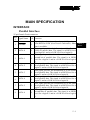
MAIN SPECIFICATION
INTERFACE
Parallel Interface
25 pin Female D-sub connector
Pin
Signal Name I/O Function
#
Signals when data is ready to be read. Signal goes
1 STROBE
I from HIGH to LOW (for at least 0.5 microsec.) when
data is available.
This signal provides the information of the first bit
2 DATA 0
I (LSB) of parallel data. The signal is at HIGH level
for a logical 1 and at a LOW level for a logical 0.
This signal provides the information of d1 the
second bit of parallel data. The signal is at HIGH
3 DATA 1
I
level for a logical 1 and at a LOW level for a logical
0.
This signal provides the information of d2 the third
4 DATA 2
I bit of parallel data. The signal is at HIGH level for a
logical 1 and at a LOW level for a logical 0.
This signal provides the information of d3 the fourth
5 DATA 3
I bit of parallel data. The signal is at HIGH level for a
logical 1 and at a LOW level for a logical 0.
This signal provides the information of d4 the fifth
6 DATA 4
I bit of parallel data. The signal is at HIGH level for a
logical 1 and at a LOW level for a logical 0.
This signal provides the information of d5 the sixth
7 DATA 5
I bit of parallel data. The signal is at HIGH level for a
logical 1 and at a LOW level for a logical 0.
This signal provides the information of d6 the
seventh bits of parallel data. The signal is at HIGH
8 DATA 6
I
level for a logical 1 and at a LOW level for a logical
0.
5-1
CHAP. 5
MAIN …
TM
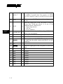
9
CHAP. 5
MAIN …
DATA 7
I
10 ACK
O
11 BUSY
O
12 PAPER END
O
13 SELECTED
O
This signal provides the information of d7 the eighth
bit (MSB) of parallel data. The signal is at HIGH
level for a logical 1 and at a LOW level for a logical
0.
A 9 microsecond LOW pulse to acknowledge receipt
of data.
When this signal goes LOW, the printer is ready to
accept data. When the printer is in one of the
conditions below, HIGH is set:
1. Data being entered
2. Off line
3. Error condition
This signal is normally LOW. It will go HIGH if the
printer runs out of paper.
This signal is HIGH when the printer is on-line.
14 N/C
15 ERROR
O
This signal is normally HIGH. This signal goes LOW
to signal that the printer cannot print due to an error
condition
16 N/C
18 GND
When this signal goes LOW, the printer is selected to
work.
Ground
19 GND
Ground
20 GND
Ground
21 GND
Ground
22 GND
Ground
23 GND
Ground
24 GND
Ground
25 GND
Ground
17 SLCTIN
5-2
I
TM
Serial Interface
9 pin Female D-sub connector
Pin Signal Name I/O Function
#
1 DCD
O Data carrier detect
2
TXD
O
Transmit data
3
RXD
I
Receive data
4
N.C.
5
GND
6
RTS
7
N.C.
8
DTR
9
N.C.
O
O
Ground
Request to send. This is always “SPACE” when the
printer is turned on.
Data terminal ready. This signal changes to
PACE” when the printer is ready to receive data.
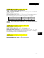
Peripheral Unit Drive
6 pin telephone jack
Pin Signal Name
#
I/O Function
1
Chassis GND
2
L1 Drive
O
3
SW Sense
I
4
+24 V DC
O
5
L2 Drive
O
6
GND
O
To connect the shield of cable between printer and
the peripheral device
Supplies a low trigger pulse to drive the circuitry L1
with a diode protection. This shall not be driven
together with L2 at the time.
To connect through diode and resistor to +24VDC
to detect the status of cash drawer open detection
switch.
Connected to +24VDC supplied by the printer.
Supplies a low trigger pulse to drive the circuitry L1
with a diode protection. This shall not be driven
together with L2 at the time.
5-3
CHAP. 5
MAIN …
TM
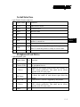
POWER SUPPLY
PIN ASSIGNMENT OF 3 PIN JACK:
PIN
DEFINITION
1
+24 V
2
GND
3
N.C.
CASE
CHASSIS GND
CASE
2
1
3
CHAP. 5
MAIN …
Fig. 18 Pin layout of power plug
HIMPORTANT: To unplug this connector, one should pull the outer sleeve of
the power plug instead of pulling the power cable itself. This connector is
equipped with a lock mechanism, pulling the cable itself without unlocking by
pulling the sleeve will cause certain damage to the connector.
OPTION LIST
• Inked ribbon cartridge
• Paper roll
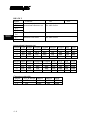
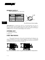
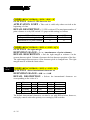
FONT MATRICES
The printed format of the fonts used is determined by the character size
which is defaulted as 15 CPI yet can be changed to 12 CPI or 8 CPI through
command received by the printer. The font format and dimension definition of
each character size is given in Fig.19 and Fig. 20.
A
A
E
E
C
C
D
F
B
D
F
B
Fig. 19 Font format for 15 CPI Fig. 20 Font format for 12 CPI and 8 CPI
5-4
TM
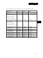
The specifications for each character size are listed in the following table:
Character size
15 CPI
12 CPI
8 CPI
Font type
7 x 9 half dot 5 x 9 full dot 5 x 9 pulse 3 full dot
For 3.25” and 3.0” paper:
Max # of columns
40
33
22
Total # of dots / row
200
198
132
65.0 mm
64.8 mm
Print area (horizontally) 65.7 mm
CHAP. 5
MAIN …
For 2.25” paper:
Max # of columns
28
23
15
Total # of dots / row
140
138
90
45.2 mm
44.1 mm
Print area (horizontally) 45.9 mm
A – dot diameter
0.30 mm
0.30 mm
0.30 mm
B – dot spacing (H)
0.330 mm
0.330 mm
0.495 mm
C – dot spacing (V)
0.353 mm
0.353 mm
0.353 mm
D – character size (H)
1.29 mm
1.62 mm
2.28 mm
E – character size (V)
2.42 mm
2.42 mm
2.42 mm
F – column spacing
1.65 mm
1.98 mm
2.97 mm
5-5
TM
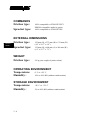
COMMANDS
Friction type:
Sprocket type:
CHAP. 5
MAIN …
100% compatible to STAR SP312FV
EPSON compatible model is option.
100% compatible to STAR SP322S
EXTERNAL DIMENSIONS
Friction type:
125 mm (H) x 273 mm (D) x 174 mm (W)
(4.9” x 10.7” x 6.9”)
Sprocket type:
WEIGHT
Friction type:
155 mm (H) x 400 mm (L) x 180 mm (W)
(6.1” x 15.7” x 7.1”)
2.4 kg (net weight of printer alone).
OPERATING ENVIRONMENT
Temperature:
0° C to +50° C
Humidity :
10% to 90% RH (without condensation)
STORAGE ENVIRONMENT
Temperature:
-20° C to +70° C
Humidity :
5% to 90% RH (without condensation)
5-6
TM
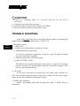
MAINTENANCE
CAUTION:
Do not open the top cover and touch the print head immediately after
printing, because the print head may be very hot.
CLEANING
• To clean the dust, paper particles, or dirt on and in the printer:
Use a vacuum cleaner to clean thoroughly.
Remove any pieces of paper from the paper path.
• To wipe off stains:
Use a clean soft dry cloth to wipe off stains.
If the stains can not be wiped off using the dry cloth, use a neutral
detergent.
CAUTION:
To avoid damaging the printer, do not use benzene, benzine, alcohol, thinner,
trichloroethylene, or ketone-based solvents on the printer’s plastic and
rubber components.
PAPER JAM
•
•
•
•
•
Turn off the printer.
Open the top cover after the print head cools down.
Cut the paper roll from the paper guide with a pair of scissors.
Turn the printer power back to on.
Press the FEED switch to forward the paper out of the paper guide. Engage
mechanical help like tweezers or manual pull if necessary.
6-1
CHAP. 6
MAINT…
TM
CAUTION:
Remove the remaining paper in a forward direction. Do not pull it
backwards.
• Clean the paper path when necessary.
• Reload the paper as instructed in “INSTALLATION”.
• Press the on-line switch to get the printer ready.
TROUBLE SHOOTING
If any of the following errors is detected while the printer is operating, the
printer halts and ERROR signal turns to “LOW” level.
CHAP. 6
MAINT…
1. Mechanical errors
• Motor lock
• Defective of timing detector (signal not issued)
• Abnormal home position check
To reset the emergency suspension, rectify the cause of trouble & adopt
one of the following 2 methods.
• Turn the printer power off and on again.
• Push “ON LINE” switch.
The RAM is not cleared immediately when power is turned OFF. Printing
resumes from the line being printed when the mechanism stopped if the
error is corrected immediately.
2. CPU error
If CPU goes erratic due to external noise, the printer halts, treating it as
CPU error. Normal operation can be resumed by turning ON the power supply
again, but the data contained in RAM gets cleared.
3. RAM Check Function
Before self printing and when clearing the buffer, a RAM check is
performed.
6-2
TM
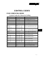
CONTROL CODES
STAR COMPATIBLE MODE
Control Codes for Character Setting
Control Codes
ESC R “n”
ESC 6
ESC 7
ESC M
ESC P
ESC :
SO
ESC W 1
ESC W <1>
DC4
ESC W 0
ESC W <0>
ESC E
ESC F
ESC - 1
ESC - <1>
ESC - 0
ESC - <0>
ESC _ 1
ESC _ <1>
ESC _ 0
ESC _ <0>
ESC 4
ESC 5
SI
DC2
Hex Codes
<1B> <52> “n”
<1B> <36>
<1B> <37>
<1B> <4D>
<1B> <50>
<1B> <3A>
<0E>
<1B> <57> <31>
<1B> <57> <01>
<14>
<1B> <57> <30>
<1B> <57> <00>
<1B> <45>
<1B> <46>
<1B> <2D> <31>
<1B> <2D> <01>
<1B> <2D> <30>
<1B> <2D> <00>
<1B> <5F> <31>
<1B> <5F> <01>
<1B> <5F> <30>
<1B> <5F> <00>
<1B> <34>
<1B> <35>
<0F>
<12>
Function
Select international character set
Select IBM character set #2
Select IBM character set #1
Select 15 CPI character size
Select 12 CPI character size
Select 8 CPI character size
Select expanded character mode
Cancel expanded character mode
Select emphasized print mode
Cancel emphasized print mode
Select underline mode
Cancel underline mode
Select overline mode
Cancel overline mode
Select highlighted print mode
Cancel highlighted print mode
Select inverted print mode
Cancel inverted print mode
7-1
CHAP. 7
CONTR…
TM
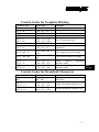
Control Codes for Line Spacing
Control Codes
LF
CR
ESC z 1
ESC z <1>
ESC 0
ESC a “n”
Hex Codes
<0A>
<0D>
<1B> <7A> <31>
<1B> <7A> <01>
<1B> <30>
<1B> <61> “n”
Function
Line feed
Line feed (same as LF)
Set 1/6 inch line feed
Set 1/8 inch line feed
Feed paper n lines
Control Codes for Page Layout
Control Codes
FF
ESC C “n”
ESC C <0> “n”
CHAP. 7
CONTR…
VT
ESC B “n1…nk”
<0>
ESC N “n”
ESC O
ESC I “n”
ESC Q “n”
HT
ESC D “n1” “n2”
7-2
Hex Codes
<0C>
<1B> <43> “n”
<1B> <43> <00>
“n”
<0B>
<1B> <42>
“n1…nk” <00>
<1B> <4E> “n”
<1B> <4F>
<1B> <6C> “n”
<1B> <51> “n”
<09>
<1B> <44> “n1”
“n2”
Function
Page feed (form feed)
Set page length at n lines
Set page length at n inches
Execute vertical tab
Set vertical tab positions
Set bottom margin
Cancel bottom margin
Set left margin
Set right margin
Execute horizontal tab
Set horizontal tab positions
TM
Control Codes for Graphics Printing
Control Codes
ESC 1
ESC A “n”
ESC 2
ESC J “n”
ESC z 0
ESC z <0>
ESC y “n”
Hex Codes
<1B> <31>
<1B> <41> “n”
<1B> <32>
<1B> <4A> “n”
<1B> <7A> <30>
<1B> <7A> <00>
<1B> <79> “n”
ESC 3 “n”
<1B> <33> “n”
ESC K “n1” <0>
ESC L “n1” “n2”
ESC h 1
ESC h <1>
ESC h 0
ESC h <0>
<1B> <4B> “n1”
<00>
<1B> <4C> “n1”
“n2”
<1B> <68> <31>
<1B> <68> <01>
<1B> <68> <30>
<1B> <68> <00>
Function
Set 7/72 inch line feed
Define n/72 inch line feed
Set n/72 inch line feed
One time line feed of n/72 inch
Set 1/12 inch line feed
Set n/144 inch line feed
Set n/216 inch line
simulation
feed
8 dot single density bit image
8 dot double density bit image
Select
vertical
character mode
Cancel
vertical
character mode
expanded
expanded
Control Codes for Download Characters
Control Codes
Hex Codes
ESC & <0> “n1” <1B> <26> <00>
“n1” “n2”
“n2”
ESC % 1
<1B> <25> <31>
ESC % <1>
<1B> <25> <01>
ESC % 0
<1B> <25> <30>
ESC % <0>
<1B> <25> <00>
Function
Definition
characters
of
down
load
Enable download character set
Disable download character set
7-3
CHAP. 7
CONTR…
TM
Control Codes for Peripheral Units
Control Codes
Hex Codes
ESC BEL “n1” “n2” <1B> <07> “n1”
“n2”
BEL
<07>
FS
<1C>
EM
SUB
<19>
<1A>
Function
Adjust drive pulse width
peripheral unit 1
Deferred drive command
peripheral unit 1
Immediate drive command
peripheral unit 1
Immediate drive command
peripheral unit 2
for
for
for
for
Other Control Codes
CHAP. 7
CONTR…
Control Codes
RS
CAN
DC3
DC1
ESC U 1
ESC U <1>
ESC U 0
ESC U <0>
ESC @
GS “data” LF
ENQ
STX
ETX
Hex Codes
<1E>
<18>
<13>
<11>
<1B> <55> <31>
<1B> <55> <01>
<1B> <55> <30>
<1B> <55> <00>
<1B> <40>
<1D> “data” <0A>
<05>
<02>
<03>
Function
Sound buzzer
Cancel print data in buffer
Select deselect mode
Set select mode
Select uni-directional print mode
Select bi-directional print mode
Initialize printer
Select validation printing of data
Enquiry
Enter STX-ETX mode
Terminate STX-ETX mode
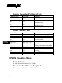
EPSON Emulation Mode
Basic Reference
PP-3000 Series Mini Printer User’s Guide.
Hardware Modification Required
Refer to page 4 - 2 Fig. 17, the BIOS at U8 should be changed.
7-4
TM
Reference Epson Models Emulated
EPSON TM-300 series.
Character Size/Font Matrices
Refer to page 5 - 4, the 8 CPI character size (5 x 9 pulse 3 full dot mode)
is not applicable for EPSON emulation.
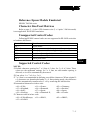
Unsupported Control Codes:
Following EPSON control codes are not supported in PP-300E series due
to hardware difference:
Control Codes
ESC <
ESC c 3
ESC c 4
ESC i
ESC m
ESC r
Function
Return home
Select paper sensor(s) for “paper-out” output signal
Select paper sensor(s) to stop printing
Partial cut (leave 1 point)
Partial cut (leave 3 points)
Select print color
CHAP. 7
CONTR…
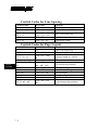
Supported Control Codes:
NOTES:
• Default character spacing for 7 x 9 font is 3 dots, for 5 x 9 is 2 dots. These
values are the minimum settings. In 5 x 9 font, no odd number spacing is
allowed, or it will be automatically decreased.
‚ Font select: 1⇒ 7 x 9; 0⇒ 5 x 9.
ƒ 7 x 9 font is recommended in defining user-define characters. When original 9
x 9 characters are downloaded under 5 x 9 font printing mode, the characters
will be automatically transferred to 5 x 9 by removing the half-dot bits.
„ Internatioal character n in hex code:
<00>⇒USA,
<01>⇒France,
<02>⇒Germany,
<03>⇒England,
<04>⇒Denmark,
<05>⇒Sweden,
<06>⇒Italy,
<07>⇒Spain,
<08>⇒Japan,
<09>⇒Norway,
<0A>⇒Denmark II,
<0B>⇒Croatia.
… Character table n in hex code:
<00>⇒USA&Europe, <01>⇒IBM 1,
<02>⇒IBM 2,
<03>⇒JAPAN.
7-5
TM
†These control codes are applicable in serial interface only.
Control Codes
HT
LF
CR
ESC SP
ESC !
•
‚
ESC %
ESC &
<1B> <25> “n”
ƒ
ESC *
ESC 2
ESC 3
ESC @
CHAP. 7
CONTR…
ESC D
ESC J
ESC R
„
ESC U
…
ESC {
7-6
<1B> <52>
<1B> <63> <35> “n”
ESC p
ESC u
ESC v
ESC =
<1B> <26> “y” “c1”
“c2” [<x> <d1> …
<d(yxx)>]c2-c1+1
<1B> <2A> “m” “nL”
“nH” [<d>]k
<1B> <32>
<1B> <33> “n”
<1B> <40>
<1B> <44> [<n>]k
<00>
<1B> <4A> “n”
<1B> <55> “n”
ESC c 5
ESC d
ESC t
Hex Codes
<09>
<0A>
<0D>
<1B> <20> “n”
<1B> <21> “n”
†
†
†
Function
Horizontal tab
Print and line feed
Print and carriage return
Set right side character spacing
Set printer mode (Font select)
Set/cancel
the
user-defined
character set
Define user-defined character set
(max. 10 characters)
Select bit image mode
Set 1/6 inch line space
Set line spacing
Initialize printer
Set horizontal tab positions
Print and feed paper
Select an international character
set
Turn uni-directional printing
mode on/off
Enable/disable panel button
<1B> <64> “n”
Print and feed n lines
pulse
(peripheral
<1B> <70> “m” “t1” Generate
device)
“t2”
<1B> <74>
Select character code table
Turn upside-down printing mode
<1B> <7B>
on/off
<1B> <73>
Transmit peripheral device status
<1B> <76>
Transmit paper sensor status
Select peripheral device
<1B> <3D> “n”
TM
APPENDIX A
STAR COMPATIBLE MODE COMMAND DETAIL
(All commands are listed in hexadecimal code sequence)
CODES (HEX/CONTROL) : 02 / <STX>
FUNCTION : Enter STX-ETX mode
APPLICATION LIMIT : This code is valid when using serial interface
printer. When IBM character set #2 is selected by character code, the code
<ETX> does not exist (In this instance, select another code).
DETAIL DESCRIPTION : STX-ETX mode is set.
CODES (HEX/CONTROL) : 03 / <ETX>
FUNCTION : Terminate STX-ETX mode
APPLICATION LIMIT : This code is valid when using serial interface
printer. When IBM character set #2 is selected by character code, the code
<ETX> does not exist (In this instance, select another code).
DETAIL DESCRIPTION : Terminates the STX-ETX mode and prints
out the text data.
CODES (HEX/CONTROL) : 05 / <ENQ>
FUNCTION : Enquiry
APPLICATION LIMIT : This code is valid when using serial interface
printer. When IBM character set #2 is selected by character code, the code
<ENQ> does not exist (In this instance, select another code).
DETAIL DESCRIPTION : Causes printer to transmit status byte (not in
STX-ETX mode). When this code is received after receiving text data in the
STX-ETX mode, the printer transmits the status and check byte.
A-1
APP. A
STAR …
TM
CODES (HEX/CONTROL) : 07 / <BEL>
FUNCTION : Deferred drive command for peripheral unit 1
DETAIL DESCRIPTION : Execute drive pulse for peripheral unit 1
when this code is processed (deferred).
CODES (HEX/CONTROL) : 09 / <HT>
FUNCTION : Execute horizontal tab.
APPLICATION LIMIT : When no horizontal tab position is set, this
code is ignored.
DETAIL DESCRIPTION : The print position skips to the next
horizontal tab position in same line. However, underline and overline do not
take place in the spaces between characters set with the horizontal tab function.
CODES (HEX/CONTROL) : 0A / <LF>
FUNCTION : Line feed
DETAIL DESCRIPTION : Data in the line buffer is printed out and one
line is fed. If data does not exist before this code is received, the printer only
feeds one line.
APP. A
STAR …
CODES (HEX/CONTROL) : 0B / <VT>
FUNCTION : Execute vertical tab.
APPLICATION LIMIT : When no vertical tab is set, line feed is not
performed.
DETAIL DESCRIPTION : Prints data before this command as <LF>
does and feeds the paper to the next vertical tab set position. If the current line is
at or below the last vertical tab set position, the paper feeds to the top of the next
page.
A-2
TM
CODES (HEX/CONTROL) : 0C / <FF>
FUNCTION : Page feed (form feed)
DETAIL DESCRIPTION : After data in the line buffer is printed out,
feeds the paper to the top of the next page.
CODES (HEX/CONTROL) : 0D / <CR>
FUNCTION : Line feed (Same as LF)
APPLICATION LIMIT : When DIP SW 1-3 of parallel interfaced
printer or DIP SW 3 - 3 of serial interfaced printer is set to ON, this code
becomes invalid (which is the default).
DETAIL DESCRIPTION : Functions the same as an LF code.
CODES (HEX/CONTROL) : 0E / <SO>
FUNCTION : Select expanded character mode
DETAIL DESCRIPTION : Data following this code is printed in
double-width characters.
CODES (HEX/CONTROL) : 0F / <SI>
FUNCTION : Select inverted print mode
APPLICATION LIMIT : This code is valid only when input at the
beginning of a line, thus, normal and inverted characters cannot be mixed in the
same line.
DETAIL DESCRIPTION : Data following this code is printed out in
inverted characters (up side down and right to left).
A-3
APP. A
STAR …
TM
CODES (HEX/CONTROL) : 11 / <DC1> or 11 n / <DC1> n
FUNCTION : Set select mode
DETAIL DESCRIPTION :
1. When using serial interface printer
This function differs depending on the setting of DIP switch 4.
a) When the DC1, DC3 invalid mode is set DIP switches 4-1 to 4-4 are all set
to ON), the printer ignores this code.
b) In the DC1, DC3 valid mode (with DIP switches 4-1 to 4-4 set to OFF),
when the printer receives a <DC1> code, the deselect mode is canceled and
data following this code is input to buffer.
c) If the printer receives a <DC1> n code (n is the DIP switch controlled
address) during the addressable mode (with DIP switches 4-1 to 4-4 set to
other settings than a) and b) above), the deselect mode is canceled and data
following this code is input to the buffer.
Note that addressable mode is valid only when optional RS-422A interface
is installed.
2. When using parallel interface printer
When the printer receives a <DC1> code, the deselect mode is canceled and
data following this code is input to the buffer.
APP. A
STAR …
CODES (HEX/CONTROL) : 12 / <DC2>
FUNCTION : Cancel inverted print mode
APPLICATION LIMIT : This code is valid only when input at the
beginning of a line.
DETAIL DESCRIPTION : Cancel the inverted character mode.
A-4
TM
CODES (HEX/CONTROL) : 13 / <DC3>
FUNCTION : Set deselect mode
DETAIL DESCRIPTION :
1. When using serial interface printer
This function differs depending on the setting of DIP switch 4.
a) When the DC1, DC3 invalid mode is set (DIP switches 4-1 to 4-4 are all
set to ON), the printer ignores this code.
b) In the DC1, DC3 valid mode (with DIP switches 4-1 to 4-4 set to OFF),
data following this code is ignored when the printer receives a<DC3>
code.
The deselect mode is canceled by <DC1> code.
c) If the printer receives a <DC3> code during an addressable mode (with
DIP switches 4-1 to 4-4 set to settings other than a) and b) above), the data
following this code is ignored.
Deselect mode can be canceled by a <DC1> n code.
Note that addressable mode is valid only when the RS-422A interface
option is installed.
2. When using parallel interface printer
Data following this code is ignored when the printer receives a <DC3> code.
The deselect mode is canceled by <DC1> code.
CODES (HEX/CONTROL) : 14 / <DC4>
FUNCTION : Cancel expanded character mode
DETAIL DESCRIPTION : Cancel expanded character mode set by
<SO> code (Data following this code is printed out in normal size characters).
CODES (HEX/CONTROL) : 18 / <CAN>
FUNCTION : Cancel print data in buffer
DETAIL DESCRIPTION :
1. When using serial interface printer
Clears the data buffer and the line buffer
Clears the data buffer in the STX-ETX mode, and terminates the STX-ETX
mode.
2. When using parallel interface printer
Clears the data buffer and the line buffer
A-5
APP. A
STAR …
TM
CODES (HEX/CONTROL) : 19 / <EM>
FUNCTION : Immediate drive command for peripheral unit 2
APPLICATION LIMIT : Peripheral units 1 and 2 cannot be driven
simultaneously.
DETAIL DESCRIPTION : Drives peripheral unit 2. Pulse width is fixed
at 200ms with a fixed delay time of 200ms. Same as <SUB>.
CODES (HEX/CONTROL) : 1A / <SUB>
FUNCTION : Immediate drive command for peripheral unit 2
APPLICATION LIMIT : Peripheral units 1 and 2 cannot be driven
simultaneously.
DETAIL DESCRIPTION : Drives peripheral unit 2. Pulse width is fixed
at 200ms with a fixed delay time of 200ms.
CODES (HEX/CONTROL) : 1B 07 n1 n2 / <ESC> <BEL> n1 n2
FUNCTION : Adjust drive pulse width for peripheral unit 1
DEFINITION RANGE : 1 ≤ n1 ≤ 127, 1 ≤ n2 ≤ 127
APPLICATION LIMIT : Adjustment is not necessary for standard cash
APP. A
STAR …
drawers in the U.S.A. market.
DETAIL DESCRIPTION : Adjusts drive pulse width for peripheral
device #1 requiring other than standard 200 ms pulse time and recovery time.
Energizing time = 10 x n1 ms
Recovery time = 10 x n2 ms
Executed by <BEL> or <FS> code.
Printing and paper feed are prohibited throughout the energizing and recovery
time.
CODES (HEX/CONTROL) : 1B 25 00 / <ESC> “%” <0>
FUNCTION : Disable download character set
DETAIL DESCRIPTION : Disable the selected download character set
and selects the built-in character set. When the power for the printer is initially
turned on, the built-in character set is selected.
A-6
TM
CODES (HEX/CONTROL) : 1B 25 01 / <ESC> “%” <1>
FUNCTION : Enable download character set
DETAIL DESCRIPTION : Enable the download character set.
Download characters defined by the <ESC> “&” <0> code cannot be printed
until enabled by this command.
CODES (HEX/CONTROL) : 1B 25 30 / <ESC> “%” “0”
FUNCTION : Disable download character set
DETAIL DESCRIPTION : Disable the selected download character set
and selects the built-in character set. When the power for the printer is initially
turned on, the built-in character set is selected.
CODES (HEX/CONTROL) : 1B 25 31 / <ESC> “%” “1”
FUNCTION : Enable download character set
DETAIL DESCRIPTION : Enable the download character set.
Download characters defined by the <ESC> “&” <0> code cannot be printed
until enabled by this command.
APP. A
STAR …
A-7
TM
CODES (HEX/CONTROL) : 1B 26 00 n1 n2 / <ESC> “&” <0> n1 n2
When 15 CPI character size is set (default setting), the detail of the code is :
1B 26 00 n1 n2 [m0 m1 m2 m3 m4 m5 m6 m7](n2-n1+1) / <ESC> “&” <0> n1 n2
[m0 m1 m2 m3 m4 m5 m6 m7](n2-n1+1)
When 8 CPI or 12 CPI character size is set, the detail of the code is :
1B 26 00 n1 n2 [m0 m1 m2 m3 m4 m5](n2-n1+1) / <ESC> “&” <0> n1 n2 [m0 m1
m2 m3 m4 m5](n2-n1+1)
FUNCTION : Definition of download characters
DEFINITION RANGE : 21H ≤ n1 ≤ n2 ≤ 7FH, m0 = 00H or 80H
APPLICATION LIMIT : When the 15 CPI character size is set (the
APP. A
STAR …
default setting), printing of adjacent horizontal dots is not allowed.
DETAIL DESCRIPTION : Defines download characters from host
computer. Up to 10 download characters can be defined and the defined
character patterns can be stored in the printer’s memory. Definitions of the
variables in the command code are as follows:
n1 and n2 represent the starting address and the ending address of the range
of download characters respectively. When defining only one character, n1 =
n2.
Each set of m0 to m7 (for 7 x 9 fonts) or m0 to m5 (for 5 x 9 fonts) defines
one download character. However, only either top 8 or bottom 8 print pins
out of total 9 print pins of the print head can be used. m0 defines which set of
pins to be used.
m1 to m7 or m1 to m5 indicates each column of the download character
pattern consecutively. Each bit in m1 to m7 or m1 to m5 defines a dot within
that column to be printed (in vertical position). The relationship of each bit
with each print pin combined with m0 can be illustrated in the following
table, where the print pin # starts count at 1 from top of the print head:
bit # of m1 to m7 or m1 to m5
8 (MSB) 7 6 5 4 3 2 1 (LSB)
engage print pin # (when m0 = 00h)
2
3 4 5 6 7 8
9
engage print pin # (when m0 = 80h)
1
2 3 4 5 6 7
8
For example, the following hexadecimal codes received under 12 CPI will define
the characters at addresses A0h, A1h and A2h to be like the graphs below when
selected:
1B 26 00 A0 A2 80 F8 A8 FF A8 F8 80 46 49 51 61 43 00 31 06 F8 06 31
A0:
A-8
A1:
A2:
TM
CODES (HEX/CONTROL) : 1B 2D 00 / <ESC> “-” <0>
FUNCTION : Cancel underline mode
DETAIL DESCRIPTION : The previously selected underline mode is
canceled for data following this code to print.
CODES (HEX/CONTROL) : 1B 2D 01 / <ESC> “-” <1>
FUNCTION : Select underline mode
DETAIL DESCRIPTION : Data following this code is printed out
underlined (However, the space generated by horizontal tab are not underlined).
CODES (HEX/CONTROL) : 1B 2D 30 / <ESC> “-” “0”
FUNCTION : Cancel underline mode
DETAIL DESCRIPTION : The previously selected underline mode is
canceled for data following this code to print.
CODES (HEX/CONTROL) : 1B 2D 31 / <ESC> “-” “1”
FUNCTION : Select underline mode
DETAIL DESCRIPTION : Data following this code is printed out
underlined (However, the space generated by horizontal tab are not underlined).
CODES (HEX/CONTROL) : 1B 30 / <ESC> “0”
FUNCTION : Set 1/8 inch line feed
DETAIL DESCRIPTION : Line feed is set at 1/8 inch after this code is
received, and is effective since first <LF> received after this command.
CODES (HEX/CONTROL) : 1B 31 / <ESC> “1”
FUNCTION : Set 7/72 inch line feed
DETAIL DESCRIPTION : Line feed is set at 7/72 inch after this code is
received, and is effective since first <LF> received after this command.
A-9
APP. A
STAR …
TM
CODES (HEX/CONTROL) : 1B 32 / <ESC> “2”
FUNCTION : Set n/72 inch line feed
DETAIL DESCRIPTION : This code sets the line feed at a defined
value with the last <ESC> “A” previously described or the default value 12, and
is effective since first <LF> received after this command.
CODES (HEX/CONTROL) : 1B 33 n / <ESC> “3” n
FUNCTION : Set n/216 inch line feed simulation
DEFINITION RANGE : 1 ≤ n ≤ 255
DETAIL DESCRIPTION : Line feed is set at n/216 inch after this code
is received, and is effective since first <LF> received after this command.
However, since the actual mechanical precision is 1/144 inch for line spacing,
the actual line feed is accomplished by simulation with integral multiplication of
1/144 inch step.
CODES (HEX/CONTROL) : 1B 34 / <ESC> “4”
FUNCTION : Select highlighted print mode
DETAIL DESCRIPTION : Prints with highlighted characters (white
APP. A
STAR …
letter on dark background). If an underline, overline or inverted print command
is input while the highlighted print mode is in effect, the highlighted mode will
be canceled and the newly input command will be executed. If a highlighted
print command is received while the underline, overline or inverted print mode
is in effect, the previously set mode is canceled and the highlighted print mode
will be set.
CODES (HEX/CONTROL) : 1B 35 / <ESC> “5”
FUNCTION : Cancel highlighted print mode
DETAIL DESCRIPTION : Cancel highlighted print mode.
A - 10
TM
CODES (HEX/CONTROL) : 1B 36 / <ESC> “6”
FUNCTION : Select IBM character set #2
APPLICATION LIMIT : This code is only valid when the character
code table set by DIP switches 2-7 and 2-8 is IBM character set #1 or #2.
DETAIL DESCRIPTION : Selects IBM character set #2.
CODES (HEX/CONTROL) : 1B 37 / <ESC> “7”
FUNCTION : Select IBM character set #1
APPLICATION LIMIT : This code is only valid when the character
code table set by DIP switches 2-7 and 2-8 is IBM character set #1 or #2.
DETAIL DESCRIPTION : Selects IBM character set #1.
CODES (HEX/CONTROL) : 1B 3A / <ESC> “:”
FUNCTION : Select 8 CPI character size
APPLICATION LIMIT : This code is valid only when received at the
beginning of a line.
DETAIL DESCRIPTION : 8 CPI character size is selected. The
maximum number of print columns is set by DIP switch (paper width setting) 25 as follows:
DIP sw 2-5
Paper width setting (inch)
Maximum no. of print columns
ON
3.25/3.0
22
OFF
2.25
15
CODES (HEX/CONTROL) : 1B 40 / <ESC> “@”
FUNCTION : Initialize printer
DETAIL DESCRIPTION : Cancels the various conditions set after the
power was turned on and resets the printer to the initial settings in effect when
the power is turned on. In this instance, contents of the line buffer and the data
buffer are not cleared, and the peripheral unit drive pulse width are not changed.
A - 11
APP. A
STAR …
TM
CODES (HEX/CONTROL) : 1B 41 n / <ESC> “A” n
FUNCTION : Define n/72 inch line feed
DEFINITION RANGE : 0 ≤ n ≤ 85 (Default n = 12)
DETAIL DESCRIPTION : This command defines <LF> line feed
spacing at n/72 inch. The actual line spacing will become the value defined by
this command whenever the <ESC> “2” code after this command is received.
CODES (HEX/CONTROL) : 1B 42 n1…nk 0 / <ESC> “B” n1…nk <0>
FUNCTION : Set vertical tab position
DEFINITION RANGE : 1 ≤ n1 < … < nk ≤ 255, 1 ≤ k ≤ 16
APPLICATION LIMIT : If a tab set position <nk> is equivalent to or
smaller than <nk - 1> just preceding the tab set position, setting of vertical tab is
assumed as complete.
DETAIL DESCRIPTION : Cancels all current vertical tab positions and
sets new vertical tab positions at lines n1, n2, etc., where n1,n2, etc. are numbers
between 1 and 255. A maximum of 16 vertical tab positions can bet set. The tab
positions must be specified in ascending order; any violation of ascending order
terminates the tab position list. Standard termination of this command itself is
done by the <0> control code. The vertical tab positions are set in terms of the
current line spacing and do not move if the line spacing is changed later.
APP. A
STAR …
CODES (HEX/CONTROL) : 1B 43 n / <ESC> “C” n
FUNCTION : Set page length at n lines
DEFINITION RANGE : 1 ≤ n ≤ 255
DETAIL DESCRIPTION : Set page length at n lines.
CODES (HEX/CONTROL) : 1B 43 00 n / <ESC> “C” <0> n
FUNCTION : Set page length at n inches
DEFINITION RANGE : 1 ≤ n ≤ 127
DETAIL DESCRIPTION : Set page length at n inches.
A - 12
TM
CODES (HEX/CONTROL) : 1B 44 n1…nk 0 / <ESC> “D” n1…nk <0>
FUNCTION : Set horizontal tab position
DEFINITION RANGE : 1 ≤ n1 < … < nk ≤ 39, 1 ≤ k ≤ 16
APPLICATION LIMIT : When the horizontal tab set position <nk> is
equivalent to or smaller than <nk-1> which is the column just preceding the set
tab position, horizontal tab setting is assumed as complete.
DETAIL DESCRIPTION : Cancels all current horizontal tab positions
and sets new tab positions at columns n1, n2, etc., in the current character pitch,
where n1, n2, etc. are numbers between 1 and 39. The maximum number of
horizontal tab positions allowed is 16. The tab positions must be specified in
ascending order; any violation of ascending order terminates the tab position list.
Standard termination is done by the <0> control code. To clear all tab positions,
specify <ESC> “D” <0>.
CODES (HEX/CONTROL) : 1B 45 / <ESC> “E”
FUNCTION : Select emphasized print mode
DETAIL DESCRIPTION : Data following this code is printed in the
emphasized print mode. In this mode, only uni-directional printing is performed.
CODES (HEX/CONTROL) : 1B 46 / <ESC> “F”
FUNCTION : Cancel emphasized print mode.
DETAIL DESCRIPTION : Cancel emphasized print mode.
APP. A
STAR …
CODES (HEX/CONTROL) : 1B 4A n / <ESC> “J” n
FUNCTION : One time line feed of n/72 inch
DEFINITION RANGE : 1 ≤ n ≤ 255
DETAIL DESCRIPTION : This code activates the n/72 inch paper feed
once.
A - 13
TM
CODES (HEX/CONTROL) : 1B 4B n1 00 / <ESC> “K” n1 <0>
1B H 4BH n1 00 m1 m2… / <ESC> “K” n1 <0> m1 m2…
FUNCTION : 8 dot single density bit image
DEFINITION RANGE : 1 ≤ n1 ≤ 200
DETAIL DESCRIPTION : This code executes 8 dot bit image print
determined by “n1”. The total number of bit image data bytes in one line is equal
to n1. The printer ignores any data bytes over the specified amount allowed in
one line. When the bit image print is finished the printer automatically returns to
the character mode. The relationship of the image data byte and the pin position
of the print head is as following, where the print pin # starts count at 1 from top
of the print head (the lowest pin # 9 is not used):
bit # of m1 , m2, etc.
engage print pin #
8
(MSB)
1
7
6
5
4
3
2
2
3
4
5
6
7
1
(LSB)
8
CODES (HEX/CONTROL) : 1B 4C n1 n2 / <ESC> “L” n1 n2
1B 4C n1 n2 m1 m2… / <ESC> “L” n1 n2 m1 m2…
APP. A
STAR …
FUNCTION : 8 dot double density bit image
DEFINITION RANGE : 1 ≤ n1 + 256 x n2 ≤ 400
APPLICATION LIMIT :
1. For double density bit image printing, dots cannot be printed overlapping
each other in the horizontal direction.
2. When printing one graphic image of a minimum of two lines with <ESC> “K”
or <ESC> “L”, feed the paper a minimum of one line before printing so that
the line spacing becomes identical between the lines.
DETAIL DESCRIPTION : This code executes double density bit image
printing (half dot printing) determined by n1 and n2. The total number of bit
image data bytes in one line is equal to n1 + n2 x 256. Refer to <ESC> “K” as to
the relation between the dot position and the bit number. The printer ignores any
data bytes over the specified amount allowed in one line. The printer does not
print adjacent dots. When the bit image printing is finished, the printer
automatically returns to the character mode.
A - 14
TM
CODES (HEX/CONTROL) : 1B 4D / <ESC> “M”
FUNCTION : Select 15 CPI character size
APPLICATION LIMIT : This code is valid only when received at the
beginning of a line.
DETAIL DESCRIPTION : 15 CPI is selected. The maximum number of
print columns is set by DIP switch (paper width setting) 2-5 as follows:
DIP sw 2-5
Paper width setting (inch)
Maximum no. of print columns
ON
3.25/3.0
40
OFF
2.25
28
When the power for the printer is turned on, 15 CPI printing is automatically
selected.
CODES (HEX/CONTROL) : 1B 4E n / <ESC> “N” n
FUNCTION : Set bottom margin
DEFINITION RANGE : 0 ≤ n ≤ 255 (Default n = 0)
DETAIL DESCRIPTION : Set bottom margin to n lines. The printer
feeds the paper to the top of the next page once the paper comes to the range of
the bottom margin within the predefined page length.
APP. A
STAR …
CODES (HEX/CONTROL) : 1B 4F / <ESC> “O”
FUNCTION : Cancel bottom margin
DETAIL DESCRIPTION : Cancel bottom margin.
A - 15
TM
CODES (HEX/CONTROL) : 1B 50 / <ESC> “P”
FUNCTION : Select 12 CPI character size
APPLICATION LIMIT : This code is valid only when received at the
beginning of a line.
DETAIL DESCRIPTION : 12 CPI is selected. The maximum number of
print columns is set by DIP switch 2-5 (paper width setting) as follows
DIP sw 2-5
Paper width setting (inch)
Maximum no. of print columns
ON
3.25/3.0
33
OFF
2.25
23
CODES (HEX/CONTROL) : 1B 51 n / <ESC> “Q” n
FUNCTION : Set right margin
DEFINITION RANGE : 2 ≤ n ≤ (maximum no. of print columns)
DETAIL DESCRIPTION : Sets the right margin at column n in the
current character pitch. Column n becomes the last character position of the line.
The right margin does not move if the character pitch is changed later. The right
margin must be within the limits above.
APP. A
STAR …
CODES (HEX/CONTROL) : 1B 52 n / <ESC> “R” n
FUNCTION : Select international character set
DEFINITION RANGE : 00H ≤ n ≤ 0AH
DETAIL DESCRIPTION : Selects the international character set
corresponding to the value of n.
n=
00H
01H
02H
03H
Country
U.S.A.
France
Germany
England
n=
04H
05H
06H
07H
Country
Denmark
Sweden
Italy
Spain
n=
08H
09H
0AH
0BH
Country
Japan
Norway
Denmark II
Croatian
The default international characters can also be set with DIP switches, however,
setting by control code takes priority over setting by DIP switches.
A - 16
TM
CODES (HEX/CONTROL) : 1B 55 00 / <ESC> “U” <0>
FUNCTION : Select bi-directional print mode
DETAIL DESCRIPTION : Returns to the standard bi-directional print
mode (This mode is set automatically when the printer power is turned on).
CODES (HEX/CONTROL) : 1B 55 01 / <ESC> “U” <1>
FUNCTION : Select uni-directional print mode
DETAIL DESCRIPTION : Prints only when the print head moves from
left to right.
CODES (HEX/CONTROL) : 1B 55 30 / <ESC> “U” “0”
FUNCTION : Select bi-directional print mode
DETAIL DESCRIPTION : Returns to the standard bi-directional print
mode (This mode is set automatically when the printer power is turned on).
CODES (HEX/CONTROL) : 1B 55 31 / <ESC> “U” “1”
FUNCTION : Select uni-directional print mode
DETAIL DESCRIPTION : Prints only when the print head moves from
left to right.
CODES (HEX/CONTROL) : 1B 57 00 / <ESC> “W” <0>
FUNCTION : Cancel expanded character mode
DETAIL DESCRIPTION : Cancel expanded character mode set by
<SO> code (Data following this code is printed out in normal size characters).
CODES (HEX/CONTROL) : 1B 57 01 / <ESC> “W” <1>
FUNCTION : Select expanded character mode
DETAIL DESCRIPTION : Data following this code is printed in
double-width characters.
A - 17
APP. A
STAR …
TM
CODES (HEX/CONTROL) : 1B 57 30 / <ESC> “W” “0”
FUNCTION : Cancel expanded character mode
DETAIL DESCRIPTION : Cancel expanded character mode set by
<SO> code (Data following this code is printed out in normal size characters).
CODES (HEX/CONTROL) : 1B 57 31 / <ESC> “W” “1”
FUNCTION : Select expanded character mode
DETAIL DESCRIPTION : Data following this code is printed in
double-width characters.
CODES (HEX/CONTROL) : 1B 5F 00 / <ESC> “_” <0>
FUNCTION : Cancel overline mode
DETAIL DESCRIPTION : Cancel overline mode.
CODES (HEX/CONTROL) : 1B 5F 01 / <ESC> “_” <1>
FUNCTION : Select overline mode
DETAIL DESCRIPTION : Data following this code is printed out with
APP. A
STAR …
an overline (However the spaces generated by horizontal tab are not overlined).
CODES (HEX/CONTROL) : 1B 5F 30 / <ESC> “_” “0”
FUNCTION : Cancel overline mode
DETAIL DESCRIPTION : Cancel overline mode.
CODES (HEX/CONTROL) : 1B 5F 31 / <ESC> “_” “1”
FUNCTION : Select overline mode
DETAIL DESCRIPTION : Data following this code is printed out with
an overline (However the spaces generated by horizontal tab are not overlined).
A - 18
TM
CODES (HEX/CONTROL) : 1B 61 n / <ESC> “a” n
FUNCTION : Feed paper n lines
DEFINITION RANGE : 1 ≤ n ≤ 127
DETAIL DESCRIPTION : After data in the line buffer is printed out,
feeds the paper n lines.
CODES (HEX/CONTROL) : 1B 68 00 / <ESC> “h” <0>
FUNCTION : Cancel vertical expanded character mode
DETAIL DESCRIPTION : Cancel vertical expanded character mode.
CODES (HEX/CONTROL) : 1B 68 01 / <ESC> “h” <1>
FUNCTION : Select vertical expanded character mode
APPLICATION LIMIT :
1. When combined with the <SO> code, this code enables printing of the
characters in two times vertical and horizontal size.
2. This code should not be combined with the inverted print mode <SI> code.
3. For the 6 x 12 dots IBM block graphic (the characters code table B0H to DFH
and F4H to F5H of IBM character set #1 and #2) of the font construction,
enlargement is only vertical in the upper 8 dots.
4. The relationship of the vertically enlarged character and the normal character
is matched at the lower level.
5. Feed the paper a minimum of one line before printing with this code.
DETAIL DESCRIPTION : This code prints characters two times the
normal vertical size after the code is received. However, the bit image mode
<ESC> “K” and <ESC> “L” are excluded.
CODES (HEX/CONTROL) : 1B 68 30 / <ESC> “h” “0”
FUNCTION : Cancel vertical expanded character mode
DETAIL DESCRIPTION : Cancel vertical expanded character mode.
A - 19
APP. A
STAR …
TM
CODES (HEX/CONTROL) : 1B 68 31 / <ESC> “h” “1”
FUNCTION : Select vertical expanded character mode
APPLICATION LIMIT :
1. When combined with the <SO> code, this code enables printing of the
characters in two times vertical and horizontal size.
2. This code is not combined with the inverted print mode <SI> code.
3. For the 6 x 12 dots IBM block graphic (the characters code table B0H to DFH
and F4H to F5H of IBM character set #1 and #2) of the font construction,
enlargement is only vertical in the upper 8 dots.
4. The relationship of the vertically enlarged character and the normal character
is matched at the lower level.
5. Feed the paper a minimum of one line before printing with this code.
DETAIL DESCRIPTION : This code prints characters two times the
normal vertical size after the code is received. However, the bit image mode
<ESC> “K” and <ESC> “L” are excluded.
CODES (HEX/CONTROL) : 1B 6C n / <ESC> “l” n
FUNCTION : Set left margin
DEFINITION RANGE : 0 ≤ n ≤ (right margin -2)
DETAIL DESCRIPTION : Set the left margin at column n in the current
APP. A
STAR …
character pitch. The left margin does not move if the character pitch is changed
later. The left margin must be at least two columns to the left of the right margin
and within the limits above.
CODES (HEX/CONTROL) : 1B 79 n / <ESC> “y” n
FUNCTION : Set n/144 inch line feed
DEFINITION RANGE : 1 ≤ n ≤ 255
DETAIL DESCRIPTION : Line feed is set at n/144 inch after this code
is received, and is effective since first <LF> received after this command.
A - 20
TM
CODES (HEX/CONTROL) : 1B 7A 00 / <ESC> “z” <0>
FUNCTION : Set 1/12 inch line feed
DETAIL DESCRIPTION : Line feed is set at 1/12 inch after this code is
received, and is effective since first <LF> received after this command.
CODES (HEX/CONTROL) : 1B 7A 01 / <ESC> “z” <1>
FUNCTION : Set 1/6 inch line feed
DETAIL DESCRIPTION : Line feed is set at 1/6 inch after this code is
received, and is effective since first <LF> received after this command.
CODES (HEX/CONTROL) : 1B 7A 30 / <ESC> “z” “0”
FUNCTION : Set 1/12 inch line feed
DETAIL DESCRIPTION : Line feed is set at 1/12 inch after this code is
received, and is effective since first <LF> received after this command.
CODES (HEX/CONTROL) : 1B 7A 31 / <ESC> “z” “1”
FUNCTION : Set 1/6 inch line feed
DETAIL DESCRIPTION : Line feed is set at 1/6 inch after this code is
received, and is effective since first <LF> received after this command.
CODES (HEX/CONTROL) : 1C / <FS>
FUNCTION : Immediate drive command for peripheral unit 1
DETAIL DESCRIPTION : Execute drive pulse for peripheral unit 1
immediately. This code differs from the <BEL> code as follows: When the
printer receives an <FS> code, the command is executed immediately. The
<BEL> code is stored in the data buffer in the same manner as other codes, and
executed in the order in which they are received.
A - 21
APP. A
STAR …
TM
CODES (HEX/CONTROL) : 1D data 0A / <GS> data <0A>
FUNCTION : Select validation printing
APPLICATION LIMIT :
1. Character data and immediate execution command <CAN> <SUB> <LF> are
valid for data.
2. Printing modes (such as emphasized, inverted, expanded character modes,
etc.) which were set before validation printing are invalid during validation
printing (These modes become valid again after validation printing is
completed).
DETAIL DESCRIPTION : Prints up to 32 columns of the 15 CPI size
characters on one line.
CODES (HEX/CONTROL) : 1E / <RS>
FUNCTION : Sound buzzer
DETAIL DESCRIPTION : A short alarm is generated by the printer.
APP. A
STAR …
A - 22