1
395
Model No, 831,24833.0
Serial No.
Writethe serial number in the space
above for reference,
Decal
* Assembly
. Operation
* Maintenance
• Part List and Drawing
Sears, Roebuck and Co.
Hoffman Estates, IL 60179
TREADMILL
EXERCISER
User's Manual
TABLE
WARNING
DECAL
IMPORTANT
BEFORE
OF CONTENTS
PLACEMENT
PRECAUTIONS
YOU BEGIN
........................................................................
PART IDENTIFICATION
ASSEMBLY
OPERATION
CHART ................................................................
................................................................................
AND ADJUSTMENT
HOW TO FOLD AND MOVE
TROUBLESHOOTING
EXERCISE
...............................................................
.....................................................
.............................................................
THE TREADMILL
...................................................
......................................................................
GUIDELINES
....................................................................
PART LIST ................................................................................
EXPLODED
DRAWING
ORDERING
REPLACEMENT
90-DAY
......................................................................
FULL WARRANTY
WARNING
PARTS ...................................................
...........................................................
DECAL
PLACEMENT
This drawing shows the location(a)
of the warning decal(s).
If a decal is
missing
or illegible,
call 1_888-533 1333 and request a free replacement
decal. Apply the decal in the location
shown. Note: The decaI(s) may not be
shown at actual size.
KEEPHANDSANDFE_AWAY
FROMTHISAREAWHILETHE
TREADMILL
ISINOPERATION,
2
_............
3
5
6
7
13
19
20
23
24
25
Back Cover
Back Cover
IMPORTANT
PRECAUTIONS
BEFORE YOU BEGIN
tive and enjoyable,
this manual, please see the back cover of this manual,
To help us assist you, note the productmodel number
and serialnumber before contacting us, The model
numberand the location of the serial number decal are
shown on the front cover of this manual
For your benefit, read this manual carefullybefore you
use the treadmill, if you have questions after reading
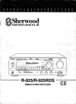
Before readingfurthez, please familiarize yourself with
the partsthat are labeled in the drawing below.
Thank you for selecting the new PROFORM ®
CROSSWALK
395 treadmill, The CROSSWALK
treadmill
designed
provides
395
an impressive
selection of features
to make your workouts
at home more effec-
Length: 5 ft. 5in, (I65 era)
Width: 2 ft. 9 in, (84 em)
|
/
Console
Storage
Crosswal
Hoed
Walking Belt
Foot Rail
Wheel
Platform Cushion
Idter Roller
Ad}ustment Screws
PART IDENTIFICATION
Use the drawings
below to identify
ing is the key number
number
tached,
CHART
small
parts used for assemb]y.
The number
in parentheses
of the part, from the PART LIST near the end of this manual,
is the quantity used for assembly. Note: If a part is not in the hardware
tf it is not, ca[J 1-888-533-1333,
Extra hardware
may be included.
betcw each draw-
The number following
the key
kit, check to see if it is preat-
I/4" Star Washer
(23)--4
#8 x !" Screw
(7)-4
#10 × 1 _12"Screw
(8)-2
3/8" Star
Washer (3)-t0
#8 x 1i2" Ground
Screw (I)-1
1/4" x 3 1/2" Screw
#8 x 3/4" Screw
(4)-4
(56)--4
D
3/8" × 3 1/4" Screw
(2)-6
ASSEMBLY
- Assembly requires two persons.
- TOidentify small pans. see page 6.
• Place all parts in a cleared area and remove
the
• Assembly requiresthe following tools:
packing materials, Do not dispose of the packing
materials until you finish assembly,
• The underside ofthe walkingbelt is coated with
high-performancelubricant. After shipping, there
may be some lubricanton top of the walking belt
or on the shipping carton. This is normal. Jfthere
is lubrica._ton top of the walking belt, wipe itoff
with a softcloth and a mild, non-abrasive cleaner.
1.
Make sure that the power cord
the includedhex keys
I_=
one Phillipsscrewdriver
SCissors
_===;z_
• To avoid damaging parts, do not use power tools,
Is unplugged.
Remove and discard the two screws (A) and the
shipping bracket (B) from the rightside of the
Base (74). Then, remove and discardthe screws
and shippingbracket (not shown) from the [eft
side ofthe Base.
74
2.
With the help of a second person, tip the treadmill onto its left side. Partially pivot the Base (74)
to hetp stablize the treadmill.
2
63
.Ground
Pull the Upright Wire (63) and the ground
through
the indicated
wire
hole in the Base (74).
Attach the ground wire to the Base (74) with a #8
x 1/2" Ground Screw (t).
See the inset drawing, Cut the plaslic tie near
the Upright Wire (63). Be careful not to damage the Upright
Wire.
Wire
Press
a Base Cap (70) into the Base
(74).
Make
sure that the Upright Grommet
(73) is
pressed
into the square
70
h(!le in the Base (74).
J
Square
Hole
4.
identify
the
"Right,"
Upright
Have a second person
near the Base (74).
Right Upright (76), which
See the inset
Right Updght
drawing.
is marked
hold the Right
Tie the wire "tie in the
(76) securely
around the end of
the Upright Wire (63). Then, insert the Upright
Wire into the lower end of the Right Upright as
you pull the other end of the wire tie through
Right Upright.
the
4
Hold
theRight Upright
(74). Re careful
(76) against the Base
not to pinch the wires.
Partially tighten three 3/8" x 3 114" Screws
(2)
w_th three 3/8" Star Washers (3) into the Right
Upright and the Base; do not fully tighten the
Screws yet.
With the help of a second person, tip the
treadmill onto its right side. Press in a Base
Cap (not shown) and attach the Left Upright
(not shown) as described in steps 3 and 5.
Note: There are no wires on the left side.
Identify the Left andRight Handrails (59, 64),
which are marked "Left" and "Right," Remove the
four 5/16"x 314" Screws (5) and four 5/16 =Star
Washers (8) from the bottoms and sides of each
Handrail,
Held the Right Handrail (64) near the Right
Upright (76). Insert the wire tie on the Upright
Wire (63) through the hole in the bottom and
out ot the hole in the side of the Left Handrail as
shown, Then, pullthe Upright Wire throughthe
Right Handrail ......................
Attach the Right Handrail (64) tOthe Right
Upright (76) with two of the 5/I6" x 3/4" Screws
(5) and two of the 3/'8"Star Washers (6) that
you jUSt removed,Make sure not to pinch the
Upright Wire (63), Start both Screws, and
then tighten them,
Attach the Left Handrail (59) to the Left UpTight
(66) as described above. Note: There are no
wires on the left side.
Position 1he Console
Crossbar (61) between
the Left and Right Handrails (59, 64) with
the Console
shown.
Attach
Ground
the Console
Wire (47) positioned
Crossbar
and Right Handrails
as
47_
{61) to the Left
64
61
(59, 64) with the other four
5/15" x 314" Screws (5) and the other four 5/t6"
Star Washers (6) that you removed in step 6,
Start all four
B.
Screws,
and then
With the help of a second
sole assembly
person,
tighten
them.
hoJd the con-
near the Right HandraiI
(64).
Connect the Upright Wire (63) to the console
wire. See the inset drawing.
The connectors
should slide together
easily and snap into
place, tf they do not, turn one connector and try
[
again, IF YOU DO NOT CONNECT
THE CONNECTORS
PROPERLY, THE CONSOLE
MAY
BECOME DAMAGED
WHEN YOU TURN ON
THE POWER,
the Upright
Then.
remove the Wire tie from
Wire.
Connect
the Console
Console
console.
Crossbar
Ground
Wire (47) on the
Console
(61) to the ground wire on the
Wire ._
lO
I
Insert the wires into the Right Handrail (64)
throughthe indicated hole as you set the console assembly on the Left and Right Handrails
(59, 64). Make sure that no wires are pinched.
Attach the console
Screws
tighten
assembly
Console Assembly
Ground
Wires
with four #8 x 314"
(4}. Start all four Screws,
them, Do not overtighten
and then
the Screws.
See assembly step 5. Firmly tighten the six 3/8"
× 3 1/4" Screws (2] on the lower ends ol the Left
and Right Uprights (66, 76) (only one side is
shown).
i
10. Attach the two Console Clamps (83) to the console assembly with four #8 x 1" Screws (7),
10
Console
Assembly
1t
11. Identify the Left and Right Upper Body Arms (84,
85),
Make sure that the Left Upper
Body Arm (84)
is positioned as shown. Attach the Left Upper
Body Arm to the Left Upright (66) w;'th two U4" ×
3 1/2" Screws (56), two 1/4" Star Washers (23),
and two 3/8" Star Washers (3) as shown, Do not
overtighten
the Screws,
Attach the Right Upper Body Arm (85) as described above.
12, Attach the Latch Housing
(67)with
the Latch
12
Spacer (82) to the Left Upright (66) with two #10
x 1 112" Screws (8); make sure that the large
hole in the Latch Housing is on the indicated
side. Start both Screws, end then tighten
them, Be careful
Screws.
not to overtighten
Locate the Latch Pin Assembly
the
(68). Remove
the
knob from the pin. Make sure that the collar and
the spring are on the pin, (Note: If there are two
collars, place one on each side of the spring,)
Insert the pin into the Latch Housing (67), Then,
tighten
the knob onto the pin,
13. Make sure that all parts are properly tightened
before you use the treadmill,
If there are sheets of plastic on the treadmill decals, remove the plastic, To protect the f_oor or carpet, place a mat under the treadmill.
Note:
Extra hardware
may be included,
used to adjust the walking
Keep the included
belt (see pages 21 and 22).
12
hex keys in a secure place;
one of the hex keys is
OPERATION AND ADJUSTMENT
HOW TO PLUG
IN THE
POWER
This productis far use on a nominal 120-volt circuit
(see drawing 1). A temporary adapter may be used to
connect the surge suppressorto a 2-pole receptacle if
a properly-grounded outlet is not available (see
drawing 2).
CORD
Grounded
II
Your treadmill,
damaged
like other electronic
by sudden voltage
equipment,
changes
can be
_
suppressor,
sea precaution
I'll
;;i,j
Box
.Grounding
!founding
Pin
pin__
in your home's
power. To decrease the risk of damaging
your
treadmill,
always usa a surge suppressor
with your
treadmill (see drawing 1 atthe right). To purchase
a surge
v
Outlet
Grounded
Oufiet
Grounding
Plug'_,
12 on page 3.
Grounded Outlet Box
Use onty a single-oUtlet
surge
suppressor
that [s
UL I449 iisted as a transient
voltage surge suppressor (TVSS). The surge suppressor
must have
a UL suppressed
voltage rating of 400 volts or tess
and a minimum surge dissipation
of 450 Joules.
_Lu__ ._apter
The surge Suppressor must be electrically
rated for
120 voRs AC and t5 amps. There must be a monitoring light on the surge
whether it is functioning
suppressor
to indicate
properly.
Failure to use a
properly.functioning
surge suppressor
age the control system of the treadmill
Metal Screw
could dam(sea precau-
_Surge
Suppressor
Grounding Ping "_"_
The temporary adapter shouldbe used only untila
pmperly-greunded outlet (see drawing 1) can be in.
stalled by a qualified electrician.
tion 13 on page 3),
This product must be grounded, If it should malfunction er break down, groundingprovidesa path
of least resistancefor electric currentto reduce the
risk of electric shock. This product'spower cordhas
an equipment*groundingconductor and a grounding
plug. P]ug the power cord into a surge suppressor,
and ptug the surge suppressor into an appropriate outlet that is properly installed and grounded
in accordance with all local codes and ordinances.
IMPORTANT: The treadmill is not compatible with
GFCl-equipped outlets and may not be compatible
with AFCFequipped out]eta.
The green-colored rigidear, lug,orthe like extending from the adapter must be connected to a parma.
neat groundsuchas a grounded outlet box cover.
The adapter must tie he_din place by a metal screw.
Some 2-pole receptacle outlet box covers are not
grounded. Contact a qualified elactric_an to determine if the outlet box cover is grounded before
using an adapter.
13
CONSOLE
FEATURES
DIAGRAM
OF THE CONSOLE
To turn on the
power, see page 15. To use the
manual
mode, sea page 15. To use a preset workout, see page 17. To use the information
mode, see
page 18.
The treadmill console offers an impressive array of
features designed to make your workouts more effective and enjoyable.
When you use the manual mode, you can change the
speed and incline of the treadmill with the touch of a
IMPORTANT:
If there is a sheet of clear plastic on
the console, remove the plastic. To prevent damage to the walking platform, wear clean athletic
button.
shoes while
As you exercise,
the console will display
exercise feedback. You can even measure
rate using the handgrip heart rate manffcr.
instant
your heart
using the treadmill.
The first time you
use the treadmill,
observe the alignment of the
ws}king belt, and center the walking belt if necessary (see pages 21 and 22).
In addition,
the console
oilers
sixteen
preset
workouts.
Eight ot these use the crosswalk arms, and the other
eight are designed to help you meet your weight-loss
Note: The console can display speed and distance
in either miles or kilometers.
To find out which unit of
goals. Each workout automatically
controls the speed
and incline of the treadmill as it guides you through an
effective exerdse session.
measurement
is selected
or to change the unit of mea-
surement, see THE INFORMATION
MODE on page
18. Note: For simplicity, all instructions in this section
refer to miles.
14
HOW TO TURN
ON THE POWER
HOW TO USE THE MANUAL
IMPORTANT: If the treadmill has been exposed to
cold temperatures, allow it to warm to room temperature before turning on the power. If you do not
do this, you may damage the console displays or
1.
other electrical
2,
IMPORTANT:
See
components,
Plug in the powercord (see
page 13). Next, locate the
power switchon the treadmill
frame near the power cord.
Press the power switchinto
the reset position.
The consote
features
Reset
_
a display
I
demo
the Stop bLrLton for a few seconds.
If the displays
remain lit, see THE INFORMATION
18 to turn off the demo mode.
MODE
on page
clip attashed to the key (see the drawing on page 14)
and slide the clip onto the waistband of your clothes.
Then, insert the key into the console. After a moment.
the displays will light. IMPORTANT:
In an emergency
ON THE POWER
at the left.
mode.
a few steps backward*
adjust
3.
Start the walking
belt.
If you press one of the numbered speed buttons,
the walking belt willgraduallychange speed untilit
reaches the selected speed setting.
situation, the key can be pulled from the console,
causing the walking belt to slow to a stop. Test the
from the console,
TURN
If you press the Start button or the Speed Increase
button, the walking belt willbegin to move at I mph.
As you exercise, change the speed ofthe walking
belt as desired by pressingthe Speed increase and
decrease buttons. Each time you press a button,
the speed settingwill change by 0.1 mph; if you
hold downa button, the speed setting willchange
in incrementsof 0.5 mph. Note: After youpress a
button, it maytake a moment for the walking belt to
reach the selectedspeed setting.
Next, stand on the foot rails of the treadmill, Find the
taking
HOWTO
Select the manual
To start the walkingbelt, press the Start button, the
Speed increase button, or one of the speed buttons
numbered 2 through 10.
you plug in the power cord and press the power
switch into the reset position, the demo mode is
turned on. To turn off the demo mode, hold down
key is not pulled
tion of the clip.
the key into the console.
When the key is inserted, the manual mode willbe
selected. If a preset workouthas been selected,
remove the key and then reinsert it.
mode, designed to be used if the treadmill is displayed in a store. If the displays light as soon as
clip by carefully
Insert
MODE
if the
To stop the walking belt, press the Stop button.
The time willbegin to flash in the display.To restart
the walkingbelt, press the Start button or the Speed
increase button.
the posi-
4, Change the incline of the treadmill as desired.
of the treadmill,press
the Incline increase
Todecrease
or
change the
buttons.
incline
%,_-_
Each time you press
the Incline increase or
decrease bLrtton,the incline w_ll change by 0.5%.
Note: After you press a button, it may take a moment for the treadmillto reach the selected incline
setting.
15
5,
Follow your
progress
with
the displays,
6,
The far left display--
Before
of clear plastic
from the metal
contacts on the
[]
i
1/4 mile (400
sion until the entire track appears.
The track will
then disappear and the indicators
to appear in succession.
will again begin
ptJlse bar. In addition, make sure
that your hands
are clean,
ILL:
show the elapsed time
and the distance that
you have walked or run.
iower
Avoid moving
your hands. When your pulse is
detected, a heart symbol in the lower right dispiay
shown. For the most accurate
continue to hold the contacts
onds,
heart rate reading,
for about 15 sec-
right
display can show tha
The
lower r{ght
dis- of
approximate
number
calodes that you have
burned and the speed of
the walking belt. The display
r_
I
!
When
!Sc!!s'l
!l
ij l
you are finished
exercising,
remove
the
key from the console,
Step onto the foot rails, press the Stop biJtton, and
adjust the incline of the treadmill to the lowest
also shows your heart
rate when you use the handgrip
(see step 6).
heart rate monitor
setting, The incline must be at the lowest setting
or you may damage the treadmitl when you fold
it to the storage position. Next, remove the key
from the console and put it in a secure place.
The upper
display--The
upper display
can show the
elapsed time,
the distance that
_
t _ t'_._1
_E
When you are finished
using the treadmill,
press
the power switch into the off position and unplug
the power cord. IMPORTANT:
If you do not do
L.l_
this, the treadmill's
wear prematurely.
you have walked or run, the approximate number
of calories that you have burned, orthe speed of
the walking belt. Press the Display button repeatedly until the upper display shows the information
that you are most interested in viewing. Note: While
_nformation is shown in the upper display, the same
information
To measure your heart rate, stand on the foot
rails and hold the metal contacts on the handrail
will flash each time your heart beats, one or two
dashes will appear, and then your heart rate will be
The lower left display will also show the incline of
the treadmill each time the incline level changes.
play--The
using the
in succes-
manual mode, the matrix
wilI display a track that
The lower left display-As you exercise, the
lower left display can
heart rate if desired,
Blm=_
BBmlalBIl!lllBIm=
m). As you exercise, the
indicators around the track will appear
your
handgrip heart
rate monitor, remove the sheets
When you select the
represents
Measure
will not be shown in the lower displays.
To reset the displays, press the Stop button, remove the key, and then reinsert the key.
16
electrical
components
may
HOW TO USE A PRESET
WORKOUT
of the profile wi[I begin to flash, If a new speed
andlor inc(ine settingis programmedfor the next
segment, the new speed and/or incline settingwill
appear in the displays, The treadmill will then automatically adjust to the new speed and/or incline
setting.
1. Insert the key into the console.
See HOW TO TURN
ON THE
POWER
on
page 15.
2.
Select
a preset workout.
To select a preset workout. press the Crosswalk
Workouts button or the
Wt. Loss Workouts button repeatedly until the
number of the desired
workout appears in the upper display,
,
If you have selected a crosswalkworkout, you will
be promptedIo use the crosswalk arms, When the
crosswalk indicator on the consolelightsup, move
the crosswalk arms forward and backward as you
walk on the treadmill. This action exercises your
arms, shoulders, and back for a total body workout,
I
The workout win continuein this way untilthe last
segmentof the profile flashes in the display and the
last segment ends. The walkingbelt wilfthen slew
to a stop,
When you select a preset workout, the incline level
of the workout will flesh in the lower left display, the
speed settingwillflash in the lowerright display,
and then the workoutlength will appear in the lower
left display. In addition, a profileof the speed settings of the workout willappear in the far left display,
Press the Start button or the Speed
button to start the workout.
If the speed or incline se_ng is too high or too low
at any time during theworkout,you can manually
overridethe setting by pressingthe speed or incline
buttons; however, when the next segment of the
workout begins, the treadmill will automatically
adjust to the speed and Incline settings for the
next segment,
increase
A moment after you press the button, the treadmill
win automatically adjust to the first speed and incline settingsof the workout, Hold the handrails and
begin walking.
Each workout is divided into 30 one-minute segments, One speed setting and one inclinesetting
are programmedfor each segment. Note: The
same speed settingand!or inclinesetting may be
programmedfor consecutive segments.
To stop the workout at any time, press the Stop
button. To restart the workout,press the Start but_
ton, The walking belt willbegin to move at 1 mph.
When the next segmentofthe workout begins, the
treadmill will automaticallyadjust to the speed and
incline settingsfor the next segment.
4. Follow your progress with the displays,
See step 5 on page 16.
5.
the profile willshow
Measure
your heart
rat_ if desired.
Current Segment
See step 6 on page 16_
• your progress. The
iIIimll
m
|lashing segment of
ll=llmJmmllm
the profile represents
mmmmllll
the currentsegment
of the workout, The
height of the flashing segment indicates the speed
setting for the current segment, At the end of each
segment, a tone will sound and thenext segment
When
you are finished
key from the console.
See step 7 on page t6,
17
exercising,
remove
the
THE
INFORMATION
HOW TO USE THE
MODE
The console features an informationmode
As you walk on the treadmill,
thatkeeps
track of the toiai distance that the walking belt has
moved ;_nd the tolal number ot I'_urs that the treadr_II
has been used. The iniormation
mode also allows
mode,
you
selected,
the following
information
To vary the intensity of your upper body e×ercise, the
resistance of the crosswalk arms can he adiusted,
To increase the resister, co, turn the resislanee kr_obs
and then
mode is
clockwise; to decrease
counterclockwise.
will be shown:
An "E" for English miles
or an "M" for metric kilometers
lower
willappear
right display.
the Speed
inthe
Press
increase
button
to change the unit of measurement
if desired.
The tower teft display will
show the tolal number of
miles
(or kilometers)
the walking
that
belt has moved.
The upper display will show
the total number of hours
the treadmitl
used,
has been
The console features a display demo mode, designed
to be used if the treadmill is displayed
in a store, While
the demo mode is lamed on, the consoIe will iunction
normafIy
when
you plug in the power
cord, press the
power switch into the reset position, and insert the
key intothe console, However, when you remove the
key, the displays will remain lit, although the buttons
will not function, tf the d_mo mode is turned on, a "d"
wig appear _ the lower right display whi[e the information mode is selected. To turn on or off the demo mode,
press the Speed
decrease
To exit the information
console.
button.
mode,
remove
you can hold the hand;
you walk on the treadmill.
hold down the Stop
button while inserting the key into the console
release the Stop button, When the information
ARMS
rails or use the c_osswalk arms. To exercise your
arms, s_oUtders, and back tar a total b_dy workout,
move the crosswalk arms forward and backward
as
to select a measurement
system of miles or kilometers,
and to turn the dis_Iay demo mode on and oil.
To seIest the information
CROSSWALK
the key from the
18
the resistance,
turn the knobs
HOW TO FOLD AND MOVE THE TREADMILL
HOW
TO FOLD THE TREADMILL
HOW TO MOVE THE
TREADMILL
Before folding
the treadmill,
adjust the incline to
the lowest posttton. If you do not do this, you may
Before moving the treadmill, fold it as described at the
[eft. CAUTION;
Make sure that the latoh pin ls fully
damage
inserted
the treadmill
when you fold it. Remove
the
key and unplug the power cord. CAUTION: YOU must
be able to eafe_y lift 45 Ibs, (20 kg) to raise, lower,
treadmill
or move the treadmill
1,
into the platform
may require
two
cushion.
Moving
the
people,
Hoidtheframeandoneofthehandraiis,
one foot against a wheel.
andplace
Hold the metal frame firmly in the ]ocstion shown
by the arrow below. CAUTION; Do not hold the
frame by the plastic foot rails, Bend your legs
and keep your back straight.
Frame
2.
Hold the frame firmly with your right hand. Pull the
]atoh knob to the left and hold it. Raise the frame
2. Pull back on the handrail untilthe treadmillwill roll
on the wheels,and carefullymove it tothe desired
location. CAUTION: Do not move the treadmill
without tipping it back, do not pull on the frame,
and do not move the treadmill over an uneven
surface.
until the hole in the p_atform cushion is aligned with
the [atoh pin. Then, slowly release the latch knob;
make sure that the tatoh pin is fuily inserted
into the platform cushion,
3. Place one foot against a wheel, and carefullylower
the treadmill
HOW TO LOWER
THE TREADMILL
FOR USE
See drawing 2. Hold the upper end of the treadmill
with your right hand. Pull the latch knob tothe left
and hold it. Next, lower the frame untilit is past
the latch pin, Make sure that the pindoes not hit
againstthe foot rail. Then, retease the latch knob.
See drawing t at the left. Hold the metal frame
firmly with both hands, and lowerit to the floor,
CAUTION: Do not hold the frame by the plastic
foot rails, and do not drop the frame. Bend your
legs and keep your back straight.
To protect the floor or carpet, place a mat under the
treadmill. Keep the treadmill out of direct sunlight.
Do not leave
temperatures
the treadmill in the storage
above 85 ° F (30 ° C).
position in
19
TROUBLESHOOTING
Most treadmill
the simple
problems
steps be]ow.
can be solved
by following
Find the symptom
appfies, and follow the steps listed. If further
assistance is needed, see the front cover of this manual
SYMPTOM:
Make
The power
does
sure that the power
c.
Remove the keyfrom
reinsert it.
d.
If the treadmill still will not run, please see the trent
cover af this manual.
that
SYMPTOM:
The console displays remain
you remove the key from the console
cord is plugged into a
a,
The console features
a display
Jit when
demo mode,
de-
I3). Use only a single-outlet
surge suppressor that
meets all of the specifications
described on page
signed to be used if the treadmill is displayed in a
store, If the displays remain lit when you remove
13. IMPORTANT:
The treadmill
is not compatible with GFCI.-equipped
outlets and may not be
the key, the demo mode is turned on. To turn off
the dome mode, hold down the Stop button for a
compatible
few seconds, If the displays are still lit, see THE
INFORMATION
MODE on page 18 to turn oft the
demo mode,
with
AFCl-equipped
outlets.
b: After the power cord has been pluggedin, make
sure that the key is insettedinto the console.
SYMPTOM:
Check the power SWitch located on the treadmill
frame near t;fie power cord. If the switch protrudes
function
as shown,
a.
the switch
has tripped.
To reset the
power switch, wait for five minutes
the switch back in.
SYMPTOM:
The power
and then press
The dlsp|ays
of the console
do not
properly
Remove the key from the console and UNPLUG
THE POWER CORD. Next, remove the five indicated #8 x 3/4" Screws
(4).
Reset
Tripped
turns
off during
use
Check the power sW_tch (see the drawing above).
If the switch has tripped, waft for five minutes and
then press the switch
b.
and then
not turn on
surge suppressor
and that the surge suppressor is
plugged into a properly-grounded
outlet (see page
a,
the console,
back in.
Make core that the power cord is plugged in. If the
power cord is plugged in, unplug it, wait for five
Carefully _iftthe Motor Hood (48) upward, and then
sIide ff forward and oft. Make sure that the Motor
minutes,
Hood does nat get caught by the tabs on the sides
of the Mator Hood.
and then plug it back in.
2O
if the walking belt is overtightened, treadmill performance may decrease and the walking belt may
become damaged, Remove the key and UNPLUG
THE POWER CORD. Usingthe hex key, turn both
id[erroller screws counterclockwise,1t4 of a turn.
When the walking belt is properlytightened, you
should be able 1olift each edge of the walking belt
2 to 3 in, (5 to 7 cm) offthe walking platlorm, Be
carefulto keep the walkingbelt centered, Then,
plugin the power cord, insertthe key, and run the
treadmill for a few minutes.Repeat untilthe walking belt is properly tightened.
Locate the Reed Switch (33) and the Magnet (32)
on the right side of the Pulley (31). Turn the Pulley
until the Magnet is aligned with the Reed Switch.
Make sure that the gap between the Magnet
and the Reed Switch
is about 1/8 in. (3 ram).
If necessary, loosen the #8 x 314" Truss Head
Screw (t4), move the Reed Switch slightly, and
then retighten the Screw. Carefully slide the Motor
Hood (not shown) back on bytining up the guides,
Reattach the Motor Hood with the five #8 x 3/4"
Screws (not shown). Then, plug in the power cord,
insert the key, and run the treadmill for a few minutes to check for a correct
speed reading.
V,ew
®
Idler Roller Screws
SYMPTOM:
change
The
incline
of the treadmill
does
not
correctly
c.
Hold down
the Stop button
and the Speed increase
button, insert the key into the console, and then
release the Stop button and the Speed increase
button. Press the Stop button and then press the
Incline increase or decrease button. The treadmill
apply silicone
the walking
calibrate the incline system. If the incline does not
begin calibrating, press the Stop button again, and
when walked
belt and cause excessive
wear,
If
d. If the walking belt still slowswhen walked on, see
the front cover of this manual.
key from the console.
belt slows
to the
you suspect that the walking belt needs more lubricant, see the front cover el this manual.
then press the Incline increase or decrease button
again. When the incline is calibrated, remove the
The walking
spray or other substances
walking belt or the walking platform unless
instructed to do so by an authorized
service representative.
Such substances
may deteriorate
will automatically
rise to the maximum incline level
and then return to the minimum level This will re-
SYMPTOM:
Your treadmill feaiures a walking belt coated with
high-performance
lubricant. IMPORTANT:
Never
on
a. Use only a single-outletsurge suppressorthat
meets all ofthe speallicaiians described on
page 13.
21
SYMPTOM:
The walking
when walked on
a.
If the walking
belt is off-center
belt is off-center,
or slips
SYMPTOM:
use
(Note_ Correcting
tirst remove the
arms
this problem
squeak
requires
key to turn the left idler roller screw clockwise 1/2
of a turn; if the walking belt has shifted to the
cone (B) and the upper
the resistance
right, turn the left idler roller screw counterclockwise 1/2 ol a turn. Be careful not to ovedighten the
body arm (C), along with
p]ate (D), plastic spacer
the resistance cone (B), Then reaftach
the order shown below.
E
G
belt slips when
move the key and UNPLUG
walked
on, first re-
THE POWER
CORD.
Using the hex key, turn both idler roller screws
clockwise, 1/4 of a turn, When the walking belt is
eoJ'rectly tightened, you should be able to 1i/1each
edge of the walking belt 2 to 3 in. (5 to 7 cm) o'i_
the walking platform. Be _aretu_ to keep the walking belt centered. Then, plug in the power cord,
insert the key, and carefully walk on the treadmill
for a few minutes.
Repeat
until the walking
(E), spring
resistance cone (B), press it back it,.) Apply a thin
layer o! white marine grease to the outer surfase of
until the walking belt is centered.
If the walking
a small
washer (F), washers (G), and thrust bearing (H).
(Note: If the resistance plate [D] comes out of the
walking belt. Then, plug in the power cord, insert
the key, and run the treadmiIi for a few minutes.
b.
during
amount o! marine grease, available at hardware
stores.) Turn the resistance knob (A) counterclockwise and remove it. Next, remove the resistance
key and UNPLUG THE POWER CORD. If the
walking belt has shifted to the left, use the hex
Repeal
The uppsrbedy
belt is
properly tightened,
22
al] parts in
EXERCISE
GUIDELINES
Burning Fat--To bum fat effectively, you must exercise at a low intensitylevel for a sustained period of
time. During the first few minutes of exercise, your
body uses carbohydratecaloriesfor energy, Only after
the first few minutes of exercise does your body begin
to use storedfat caloriesfor energy. If your goal is to
bum fat, adjustthe intensityof your exercise untilyour
heart rate is near the lowest number in your training
zone. For maximum fat burning, exercise with your
heart rate sear the middle number in your training
zone.
These guidelines will help youto plan your exercise
program. For detailedexercise information,obtain a
reputable book or consult your physician. Remember,
proper nutrition and adequate rest are essential for
successfulresults.
Aerobic Exercise--If your goal is to strengthenyour
cardiovascularsystem, you must performaerobic
exercise, whichis activity that requiresfargo amounts
of oxygen for prolonged periodsof time. For aerobic
exercise, adjust the intensityof your exercise untilyour
heart rate is near the highest number in your training
zone.
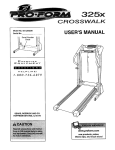
WORKOUT
GUIDELINES
EXERCISE INTENSITY
Whether
your goal is to burn fat or to strengthen
your
cardiovascular
system, exercising at the proper intensity is the key to achieving
results, You can use your
heart rate as a guide to find the proper intensity level.
The chart below shows recommended
head rates for
fat
burning
and aerobic
exercise.
165
155 145
140
130 125
115
145
138 130
125
118
110
103
125 120
115
I10
105
95
90
20
40
50
60
70
80
30
I_
Warming Up--Start with 5 to 10 minutes otstretching andlight exercise,A warm-up increasesyour body
temperature, heart rate, and circulationin preparation
for exercise.
Training Zone Exercise--Exercise for 20 to 30 minutes with yourheart rate in yourtraining zone. (During
the first few weeks of your exercise program, do not
keep your heartrate in yourtraining zone for longer
than 20 minutes.) Breathe regularly and deeply as you
exercise--never hold your breath.
Cooling Down_Finish with S to 10 minutes of stretching.Stretching increasesthe flexibility of your muscles
and helpsto prevent post-exerciseproblems.
_1
EXERCISE
To find the proper intensity level, find your age at the
To maintain or improve your condition,complete three
workers each week, with at least one day of rest
between workouts.After a few months of regular exercise, you may complete up to five workoutseach week,
it desired. Remember,the key to success is to make
exercise a regular and enjoyable part ofyour everyday
life,
bottom of the chart (ages are rounded off to the nearest fen years), The three numbers listed above your
age define your "training zone." The lowest number is
the heart rate for fat burning, the middle number is the
heart rate for maximum fat burning, and the highest
number
is the heart rate for aerobic
FREQUENCY
exercise.
23
PART LIST
Model
Key No.
Qty.
1
2
8
6
#8 x 1/2" Ground Screw
3/8" x 3 1/4" Screw
Description
3
4
10
31
3/8" Star Washer
#8 × 3/4." Screw
No. 831.24833.0
Key No.
Qty.
45
1
5/32" Rex Key
46
47
1
1
Right Rear Foot
Console Ground
1
1
Motor Hood
Incline Motor
Description
Wire
5
8
5/t 6" x 3/4 _Screw
48
49
6
7
8
4
5/16" Star Washer
#Sx !" Screw
50
51
2
t
Lift Frame
Lift Frame
8
9
2
2
#10xl
112" Screw
3/8" x 2 1/2" Bolt
10
tl
12
t
2
2
Incline Motor Spacer
M8 × 50ram Screw
318" x 1" Bolt
52
53
54
1
1
1
Belly Pan
Power Cord Grommet
Power Cord
55
56
1
4
Power Switch
1/4" x 3 1/2" Screw
13
14
3
19
Hood Clip
#8 x 3t4" Truss
57
58
1
1
Console
Console
15
16
17
1
6
2
3/8" ×1 3/4" Bolt
8/8" Jam Nut
1/4"x
3/8" Screw
59
1
Left Handrail
80
81
2
1
Lower HandraiI Cap
Console Crossbar
18
4
#8 × 1/2" Screw
62
1
Key/Clip
19
20
4
4
5t16" × 1 1/2" Bolt
5/16" Nut
63
64
1
1
Upright Wire
Right Handrail
2I
22
2
2
Upper Handrail Cap
#8 Star Washer
65
68
2
1
Upper Body Arm Insert
Lef_ Upright
23
24
25
4
2
2
1/4" Star Washer
Drive Roller Washer
1/4"x I 1/4" Screw
67
88
1
1
Latch Housing
Latch Pin Assembly
26
2
Incline Frame
27
28
1
2
Left Foot Rail
Platform Cushion
59
70
71
72
2
4
2
2
Warning Decal
Base Cap
Thick Base Pad
Thin Base Pad
29
30
1
2
Caution Decal
Belt Guide
73
74
1
1
Upright Grommet
Base
31
32
33
1
1
1
Drive Roller/Pulley
Magnet
Reed Switch
75
2
Wheel
34
35
36
1
1
1
Reed Switch
Drive Motor
Controller
76
77
78
1
2
8
Righf Uptight
Lift Frame Pin
#8 x 3/4" Tek Screw
79
80
2
1
1/4" Star Washer
3/8" x I 1/2 _ Bolt
37
38
1
f
ConttolIer
Frame
81
2
Wire _e
39
40
1
t
Walking
Walking
82
83
1
2
Latch Spacer
Console Clamp
41
42
43
1
1
1
Right Foot Rail
taller Roller
Left Rear Foot
84
85
86
87
1
t
2
8
Left Upper Body Arm
Right Upper BodyArm
#10 x 3/4" Screw
#10 Fiat Washer
44
1
Hex Key
-
User's Manual
Head Screw
Washer
Clamp
Plate
Platform
Belt
Note: Specifications
are subject to change without notice. For information about
the back cover of this manual. *These pads are not illusttated.
24
R0811A
ordedng
Bushing
Base
replacement
parts, see
35
33
m_
x
r
0
m
27
m
Z
29
4O
39
¢Jq
43
E_
-,n
::=.
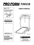
EXPLODED
DRAWING
B
Mode] No. 83"[.24833.0
"'L_3
48
26
16-_,_; '.
"_"_
i8o
d. "e-26
4
4
26
RO811A
EXPLODED
DRAWING
C
Model No, 831.24833,0
R0811A
4
4
62
4
81
59
6O
4
12
69
9
74
3
2
16 75
27
Your Home
For repair--in your home--of all major brand appliances, lawn and garden equipment,
or heating and cooling systems, no matter who made it, no matter who sold it]
For the replacement parts, accessories, and user's manuals that you need to do-it-yourself.
For Sears professional installation of home appliances
and items like garage door openers and water heaters.
1-800-4-MY-HOME ® (1-800,469-4663)
Call a_ytime,day or night(U.S.A.and Canada)
www',se_lrs,Gom
wv_w, se_rs,ca
Our Home
i:':_._i:!
For repair of carry-in items like vacuums, lawn equipment,
and electronics, call or go on-line for the location of your nearest
Sears Parts & Repair Center.
!i:;,!i_i':
_i_::_
ii!ii
1-800-488-1222
TO purchase a proteclion agreement (U.S,A.)
or maintenance agreement {Canada) on a product serviced by Sears:
:_
1-800-827_6655
_!
Call anytime,day_r night(U.S,A.only)
(U.8_..)
1-800-361-6665
(C_-ada)
Para pedir servicio de reparaci6n a domidlio, y para ordenar piezas:
_;_"_,.
1-888-SU-H OGAR _ (_-888_784--_427)
"_i:_i__
_.....
90-DAY FULL WARRANTY
If this Sears Treadmill
Exerciser
fairs due to a defect in material
date of purchase, call 1-890_-MY-HOME
if repair proves impossible), The frame
or workmanship
within 90 days of the
_ (1-800-469-4663)
to arrange for free repair (or replacement
and drive motor are warranted
for five (5) years from the date of
purchase,
This warranty" does not apply" when the Treadmill
This warranty
state.
gives you specific
Sears,
Pa_ No. 316020
R0811A
legal rights,
Roebuck
Exerciser
is used commercially
or for rental
purposes.
and you may also have other dghts which vary from
and Co., Hoffman
Estates,
state to
IL 60179
Printed
in China © 2011 ICON
IP, ]nC,