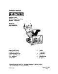
1
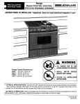
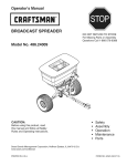
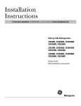
Owner's Manual
CRRFT$14RN
48" SPIKE AERATOR
Model No. 486.24372
•
•
•
•
•
CAUTION:
Before using this product,
read this manual and follow
all Safety Rules and
Operating Instructions.
Sears, Roebuck and Co., Hoffman
PRINTED
IN U,S.A.
Estates,
IL 60179 U.S.A.
Safety
Assembly
Operation
Maintenance
Parts
SAFETY RULES .......................................................
FULL SIZE HARDWARE CHART ............................
ASSEMBLY ...............................................................
OPERATION
.............................................................
MAINTENANCE
........................................................
2
3
4
6
7
SERVICE AND ADJUSTMENTS
..............................
STORAGE .................................................................
REPAIR PARTS ILLUSTRATION
...........................
REPAIR PARTS LIST ...............................................
PARTS
ORDERING/SERVICE
.................
7
7
8
9
Back Page
LIMITED ONE YEAR WARRANTY ON
For one year from the date of purchase, when this aerator is maintained and lubricated accordingto the operatingand
maintenance instructions in the owner's manual, Sears will repair any defect in material or workmanship free of charge.
If this aerator is used for commercial or rental purposes, this warranty applies for only 90 days from the date of purchase.
This warrantydoes notcover repairsnecessary because of operator negligenceor abuse, includingthe failure to maintain
the equipment according to instructions contained in the owner's manual. ,
WARRANTY
SERVICE IS AVAILABLE BY CONTACTING
THE NEAREST SEARS SERVICE
CENTER/DEPARTMENT
IN THE UNITED STATES.
This warrantyapplies only while this productis in the United States.
This warrantygives you specificlegal rights,and you may also have other rightswhich vary from state to state.
Sears, Roebuck and Co. D/817 WA. Hoffman Estates, Chicago, IL 60179
Any power equipment can cause injury if operated improperly or if the user does not understand how to operate
the equipment. Exercise caution at all times, when using power equipment.
•
•
•
•
•
•
•
Read the owners manual carefullyfor operating and
service instructions before attempting to assemble or
operate this equipment. Be thoroughly familiar with
the proper use of this equipment.
Read the vehicle owners manual and vehicle safety
rules, and know how to operate the vehicle before
using this equipment.
Never allow children to operate the tractor or spike
aerator attachment, and do not allow adults to operate
without proper instructions.
Wear eye protection when operating the aerator.
Wear substantial footwear when operating the
aerator.
Do not allow anyone to ride or sit on spike aerator
attachment frame or on towing vehicle.
Keep the area of operation clear of all persons,
particularly small children, and also pets.
•
•
•
•
•
•
Always begin with the transmission in first (low) gear
and engine at low speed, and gradually increase
speed as conditionspermit.
The vehicle brakingand stabilitymay be affectedwith
the attachmentof this equipment. Be aware of
changingconditionsonslopes. Refer to safety rules in
the vehicleowner's manual concerningsafe operation
on slopes. STAY OFF OF STEEP SLOPES.
Always operate up and down a slope, never across
the face of a slope
This equipmentshouldbe operated at reduced speed
on roughterrain, along creeks and ditchesand on
hillsides,to preventtipping and loss of control. Do not
drivetoo close to a creek or a ditch.
Do nottow this equipment on a highway or any other
publicthoroughfare.
Followthe maintenance instructionsas outlined in this
owners manual.
Look for this symbol to point out important safety precautions. It mean--Attention!!
Become alert!! Your safety Is involved.
The model number and serial number will be found on a
decal attached to the spike shield.
You should record both the serial number and the date of
purchase and keep in a safe place for future reference.
MODEL NUMBER:
SERIAL NUMBER:
DATE OF PURCHASE:
486.24372
I
I
I
SHOWN ACTUAL
NOT SHOWN
REF. I QTY.
A
B
C
D
E
F
G
H
I
2
2
2
2
2
2
2
6
4
SIZE
ACTUAL
DESCRIPTION
REF.
J
K
L
M
N
O
P
Q
R
S
Hex Bolt, 3/8-16 x 2-1/2" Lg.
Hex Bolt, 3/8-16 x 1" Lg.
Hex Bolt, 5/16-18 x 2" Lg.
Hex Bolt, 5/16-18 x 1-1/4" Lg.
Hex Bolt, 5/16-18 x 1" Lg.
Hex Bolt, 5/16-18 x 3/4" Lg.
Carriage Bolt, 5/16-18 x 1" Lg.
Hex Nut, 5/16"
Hex Lock Nut, 5/16"
3
SIZE
QTY.
4
6
2
2
2
2
2
2
2
2
DESCRIPTION
Hex Lock Nut, 3/8"
Lock Washer, 5/16"
Lock Washer, 3/8"
Flat Washer, 5/16"
Flat Washer, 3/8"
Axle Bushing
Bushing,Short
Clevis Pin, 3/8" x 3/4" Lg.
Hairpin Cotter, 3/32"
Grip
CARTON
CONTENTS
1. Spike Shield Assembly
2. Hitch Mount Arm (2)
3.
4.
Hitch Bracket (2)
Wheel Assembly (2)
5. Hitch Arm Mount Bracket (2)
6. Transport Handle (2)
Hardware Package (Page 3)
6
4
TOOLS REQUIRED FOR ASSEMBLY
Assemble two hitch arm mount brackets to the
spike shield assembly using two 5/16" x 3/4" hex
bolts and 5/16" hex lock nuts. Do not tighten at yet.
See figure 1.
(2) 1/2" Wrenches
(2) 9/16" Wrenches
HITCH ARM MOUNT
REMOVAL
OF PARTS
FROM
_ _,..5/16" x 3/4'"
_'_HEX BOLT
CARTON
SPIKE SHIELD
ASSEMBLY
Remove all parts and hardware packages from the
carton. Lay out all parts and hardware and identify
using the illustration on page 3 and the illustration at
the top of this page.
i
_'<"_'5/16'"
HEX
LOCK NUT
FIGURE 1
4
•
Slide the two hitch mount arms through the slots in
the rear flange of the spike shield. Fasten the arms to
the outside of the mount brackets using two 5/16" x 1"
carriage bolts, two 5/16" lock washers and two 5/16"
hex nuts. See figure 2. Do not tighten at this time.
RUBBERGRiP 3/8 "° HEX LOCK
TRANSPOP#r \
NUT_
_/
HANDLE
_L _
318"x 1" \
/JIpe_;"7
HEX BOLT \ _
_"-
Assemble the ends of the two hitch mount arms
together using two 5/16" x 1-1/4" hex bolts, two 5/16"
lock washers and two 5/16" hex nuts. See figure 2.
Do not tighten at this time.
/
I 3,8..
/
LOCK
///
' I
Assemble the two hitch brackets to the top and
bottom of the hitch mount arms using two 5/16" x 2"
hex bolts, two 5/16" lock washers and two 5/16" hex
nuts. The bolts shouldpass between the two bolts
assembled in previous step. See figure 2. Tighten all
bolts at this time.
SPIKE SHIELD
ASSEMBLY
-
LAT
WAS..
,,t,.., 1..HEX
BOLT
8UBH,NG
_'318"' FLAT WASHER
3/8" _ 2-1/2" HE)( BOLT
(2) HITCH ARM
MOUNT
BRACKETS
(2) 5/16" x 1"
CARRIAGE BOLTS
(2) HITCH
MOUNT
ARMS-
FIGURE 3
(2) 5/16" x 2"
HEX BOLTS
Move each transporthandle forward until it rests
againstthe bushingassembled in figure 3. Lock the
handle in this positionwith a clevis pin and a hairpin
cotter as shown in figure 4, The aerator is now in the
transportmode.
'_'_
Move the towing vehicle onto a level surface, such as
a ddveway or garage floor, and connect the aerator to
the vehicle. See figure 4.
I
A
Remove the clevis pins and move the transport
handle toward the rear of the aerator shield untilthe
spikes come to rest on the driveway or floor,The
aerator is now in the operatingmode. See figure 4.
(6) 5/16" LOCK/
WASHERS
(6) 5/16"
HEX NUTS
/
(2) 5/16" x 1-1/4"
HEX BOLTS
(2) HITCH
BRACKETS
To level the spike shield, loosenthe carriage bolts
fastening the hitch mount arms to the brackets. Adjust
spike shield as level as possible. See figure 4.
FIGURE 2
Tighten the hex nuts on the carriage bolts to lock
spike shield in level position.See figure 4.
Assemble a bushing to the bottom front hole in each
end plate on the spike shield assembly. Use two 5/16"
x 1" hex bolts, 5/16" flat washers and 5/_16"hex lock
nuts. Tighten securely. See figure 3.
•
HANDLE BACK
FOR OPERATiNG
MODE
Assemble a wheel to the end hole in each transport
handle using a 3/8" x 2-1/2" hex bolt, 3/8" flat washer,
axle bushing, 3/8" lock washer and 3/8" hex lock nut.
Tighten securely. See figure 3.
-• ":-_
- •
i
•
TRANSPORT
MODE
MOUNT
BRACKET
\•"
"-.
•
_16"X1"
CARRIAGE
BOLT
Install a rubber grip on each transport handle. See
figure 3.
_,
IoO I L_
SPIKE
SHIELD
Assemble a transport handle with wheel to the bottom
middle hole in each end plate as shown in figure 3.
Use a 3/8" x 1" hex bolt and 3/8" hex lock nut.
Tighten, but do not over tighten; the handle must
pivot freely.
PiN AND
HAIRPIN co'n'ER
iI
FIGURE4
5
KNOW YOUR SPIKE AERATOR
HOW TO USE YOUR
Read this owner's manual and safety rules before
operating your spike aerator.
Aerating means cutting small holes in the soil to create
small reservoirs that will bring oxygen, fertilizer and
water down into the root zone. For best performance of
the spike aerator, the following preparation and operation is recommended.
Compare the illustrationbelow with your spike aerator to
familiarize yourself with the various controls and their
locations.
&
HITCH ARM
TRANSPORT
HANDLE
SPIKE AERATOR
CAUTION: Aerator points are sharp.
Be careful when servicing or operating
the aerator.
MOUNT
BRACKET
Mow the lawn and remove loose clippings before
using the aerator.
\
Drive to starting point with aerator in transport
mode.
Lower aerator spikes by pulling the transport
handles back.
Set the tractor throttle at slow speed and engage
the shift lever in the lowest possible forward speed.
Increase speed as conditions permit.
CLEVIS PIN
FIGURE
5
Aerate in the straightest line possible, making
overlapping passes to increase spike point pattern.
HITCH ARM MOUNT BRACKET Allows the aerator
to be levelled front to back for different tractor
hitches.
To avoid damage to your lawn, DO NOT TURN
SHARPLY with the spike points engaged in the
ground.
TRANSPORT HANDLE Raises the aerator points off
the ground for transport.
On sloped lawns, aerate_n an up and down direction.
DO NOT attempt to follow the contourof the ground.
CLEVIS PIN Locks the transport handle in transport
position. Secured with a hair cotter pin.
DO NOT attempt to aerate ifthe groundis too hard
and dry or if it istoo wet (muddy).
OPERATING
TIPS
To increasespike point depth penetration, add weight
to the upper frame as required.rhe frame holds
three concreteblocks or patio blocks at approximately
35 Ibs.each. Secure the weightswith straps or wire,
usingthe holes in the shield flange. See figure 5 on
this page.
•
6
If the ground is extremely hard and dry, it is recommended that it be sprinkled or watered down for one
to two hours prior to use of the aerator.
CUSTOMER
•
RESPONSIBILITIES
Read and follow the maintenance schedule and the maintenance procedures listed in this section.
MAINTENANCE SCHEDULE
F,,indates
asyou
complete regular service.
_.,,_o_
.do,
F
Service Dates
,_°_,t,,_t_F
Checkforloosefasteners
Lubricate
wheelbearings
Cleaninq
X
X
X
CHECK FOR LOOSE FASTENERS
•
Before each use make a thorough visual check of
the snow thrower for any bolts and nuts which may
have loosened. Retighten any loose bolts and nuts.
LUBRICATION
• Oil the wheel bearings at least once every season.
Refer to figure 6.
CLEANING
•
Clean off dirt after each use.
FIGURE 6
SHARPENING
•
STORAGE
•
•
SPIKE
POINTS
Spike points can periodically be sharpened with a
small grinder to maintain good penetration. The
spike disks should be removed from the aerator to
sharpen the points.
RECOMMENDATIONS
Store in a dry area.
If rust appears on shield or spikes, sand lightly and
coat with enamel paint.
REPAIR
PARTS
FOR MODEL
486.24372
29
\
9
2O
12
18
/
25
16
26
/
31
31
11
D
26
/
26 25
13
26
25
REPAIR PARTS FOR MODEL
:IEF.
1
2
3
4
5
6
7
8
9
i10
11
12
13
14
15
16
17
18
19
20
21
22
23
24
25
26
27
28
29
3O
31
32
33
34
35
PART NO.
QTY,
24111
23900
45148
24113
23903
45187
43182
43064
43009
23904
23981
23905
23914
23442
44238
43432
43001
43003
43070
43082
23906
43182
43063
44326
43086
43083
23625
43055
43943
43081
44180
43840
44044
46497
46584
47531
1
20
20
1
2
2
8
4
4
1
2
2
2
2
2
2
2
2
2
4
2
2
2
2
6
6
2
2
2
2
2
2
2
20
8
1
486.24372
48" SPIKE AERATOR
DESCRIPTION
Spike Shield - 48"
Spike Disk
Spike Disk Hub
Axle
End Plate
Spring Pin, 1/4" x 2" Long
Hex Head Bolt, 5/16-18 x 3/4" Long *
Hex Lock Nut, 5/16-18 Thread *
Flat Washer, 1.59 O.D. x 25/32 I.D.
Reinforcement Bracket
Hitch Bracket
Transport Bar
Hitch Arm
Hitch Arm Mounting Bracket
Wheel
Hex Bolt, 3/8-16 x 2-1/2" Lg. *
Hex Bolt, 3/8-:16 x 1" Lg. *
Lock Washer, 3/8"
Flat Washer, 3/8"
Hex Lock Nut 3/8-16 Thread *
Axle Bushing
Hex Bolt, 5/16-18 x 3/4" Lg. *
Hex Bolt, 5/16-18 x 1" Lg. *
Carriage Bolt, 5/16-18 x 1" Lg. *
Lock Washer, 5/16" *
Hex Nut, 5/16-18 Thread *
Bushing, Short
Hairpin Cotter 3/32"
Grip
Flat Washer, 5/16" *
Hex Bolt, 5/16-18 x 2" Lg. *
Hex Bolt, 5/16-18 x 1-1/4" Lg. *
Pin, Clevis 3/8" x 3/4" Lg.
Spacer Tube, 1" O.D. x 1.2" Lg.
Nut, Whizlock 5_'16-18 Thread
Owners Manual
*Purchase commonhardware locally.
NOTES
10
NOTES
11
For in-home major brand repair service:
Call 24 hours a day, 7 days a week
1-800-4-MY-HOME"
(1-800-469-4663)
Para pedir servicio de reparaci6n a domicilio - 1-800-676-5811
In Canada for all your service and parts needs call - 1-800-665-4455
Au Canada pour tout le service ou les pibces
For the repair or replacement parts _,ou need:
Call 7 am - 7 pm, 7 days a week
1-800-366-PART (1-800-366-7278)
Para ordenar piezas con entrega a domicilio - 1-800-659-7084
For the location of a Sears Parts and Repair Center in your area:
Call 24 hours a day, 7 days a week
1-800-488-1222
For information on purchasing a Sears Maintenance Agreement
or to inquire about an existing Agreement:
Call 9 am - 5 pm, Monday - Saturday
1-800-827-6655
SEARS
HomeCentral"
I
J
TheServiceSideof Sears"
PRINTED
IN U.S.A.
FORM NO. 47531 (1/99)