1
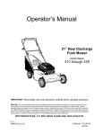
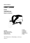
Owner's Manual
9 Horse Power
28" Two-Stage Track Drive
Snow Thrower
Model No.
247.888550
CAUTION: Before
using this product,
read this manual and
follow all safety rules
and operating
instructions.
•
•
•
•
•
•
Safety
Assembly
Operation
Service
Maintenance
Espafiol
Sears, Roebuck And Co., Hoffman Estates, IL 60179, U.S.A.
Visit our Sears website: www.sears.condcraftsman
PdntedJnU.S.A.
FormNo.770-10051C
(6/99)
Content
Page
Content
Page
Warranty Information......................................... 2
Service & Adjustment......................................... 20
Safe Operation Practices ................................... 3
Off*Season Storage ........................................... 24
Hardware Pack .................................................. 5
Trouble-Shooting............................................... 25
Assembly ........................................................... 6
Parts List............................................................ 26
Operation ............... ............................................ 12
Espanbl.............................................................. 40
Maintenance ...................................................... 17
Two -Year Warranty on Craftsman Snow Thrower
For two years from the date of purchase, when this Craftsman Snow Thrower is maintained, lubricated and tuned
up according to the instructionsin the owner's manual, Sears will repair, free of charge, any defect in material
and workmanship.
If this Craftsman snow thrower is used for commercial or rental purposes, this warranty applies for only 30 days
from the date of purchase.
This warranty does not cover:
Expendable items which become worn during normal use, such as skid shoes, shave plate and spark
plugs.
Repairs nec•ssary because of operator abuse or negligence, includingbent crankshaftsand the failure to
maintain the equipment according to the instructionscontained in the owner's manual.
WARRANTY SERVICE IS AVAILABLEBY RETURNING THE CRAFTSMAN SNOW THROWER TO THE NEAREST
SEARS SERVICE CENTER/DEPARTMENT IN THE UNITED STATES.
This warranty applies only while this product Is In use in the United States.
Thiswarrantygivesyou specificlegal rightsand you may also haveotherdghts whichmay vary from stateto state.
SEARS, ROEBUCK AND CO., D/817WA, HOFFMAN ESTATES,IL 60179
Horsepower:
9
Engine Oil
SAE 5W30 oil
Fuel Capacity:
1 gallon
Spark Plug:
RJ-19LM
Engine:
143.999005
Model Number
247.888550
Serial Number ...........................................................
Date of Purchase ......................................................
Record both serial number and date of purchase and
keep in a safe place for future reference.
This symbol points out important safety instructions which, ifnot followed, could endanger the
personal safety and/or propertyof yourself and others. Read and follow all instructions in this manual
before attempting to operate your snow thrower. Failure to complywith these instructionsmay resultin
personal injury.When you see this symbol--heed its warning.
,_
Your snow thrower was built to be operated accordingto the rules for safe operation in this manual. As
DANGER" with any type of power equipment carelessness or erroron the part of the operator can result in serious
in ury. f you v o ate any of these rules, you may cause serious njuryto yourself or others.
forest-covered,
brush-coveredor
grass-coveredland
unlessthe
engine'sexhaustsystemis
equippedwitha
Thisunitisequippedwith
an internalcombustion
engineand
shouldnotbe
usedon or near any
unimproved
sparkarrestermeetingapplicablelocalor state laws(ifany). If a sparkarresteris used,it shouldbe
maintainedin effectiveworkingorderby theoperator.
In the State ofCaliforniathe above isrequiredby law (Section4442 ofthe CaliforniaPublicResources
Code). Other states may have similarlaws. Federal lawsapplyon federal lands.A spark arresterfor the
mufflerisavailablethroughyournearestSearsAuthorizedServiceCenter(See the REPAIR PARTS section
ofthismanual.)
TRAINING
Read thisowner's guide carefully in itsentirety before
attempting to assemble or operate this machine. Be
completely familiar with the controlsand the proper
use of this machine before operating it. Keep this
manual in a safe place for future and regular
reference and for orderingreplacement parts.
Never allow children under 14 years old to operate a
snowthrower. Children 14 years old and over should
only operate a snow thrower underclose parental
supervision. Only persons well acquainted with these
rules of safe operationshould be allowed to use your
snow thrower.
No one should operate thisunit while intoxicated or
while taking medicationthat impairsthe senses or
reactions.
Keep the area of operationclear of all persons,
especially small children and pets.
Exercise caution to avoid slippingor falling,especially
when operating in reverse.
PREPARATION
Thoroughly inspect the area where the equipment is
to be used and remove all door mats, sleds, boards,
wires and other foreign objects.
Do not operate equipment withoutwearing adequate
outer garments for winter. Do not wear jewelry, long
scarfs or other loose clothing which could become
entangled in moving parts. Wear footwear which will
improve footingon slipperysurfaces.
Before workingwith gasoline, extinguishalt cigarettes
and other sources of ignition. Check the fuel before
startingthe engine. Gasoline is an extremely
flammable fuel. Do not fillthe gasoline tank indoors,
while the engine is running, or untilengine has been
allowed to cool at least two minutes. Replace
gasoline cap securely and wipe off any spilled
gasoline before startingthe engine as it may cause a
fire or explosion.
Use a grounded three wire plug-in for all units with
electric drive motors or electric starting motors.
Adjustcollector housing height to clear gravel or
crushed rock surface.
Never attempt to make any adjustments while engine
is running(except where specifically recommended
by manufacturer).
Let engine and machine adjust to outdoor
temperature before startingto clear snow.
Always wear safety glasses or eye shields during
operationor while performingan adjustment or repair,
to protect eyes from foreign objects that may be
thrown from the machine in any direction.
OPERATION
Do not put hands or feet near or under rotatingparts.
Keep clear of discharge opening and auger at all
times.
Exercise extreme caution when operatingon or
crossinggravel drives, walks, or roads. Stay alert for
hidden hazards or traffic.
Do not carry passengers.
After strikinga foreign object, stop the engine, remove
wire from the spark plug and thoroughlyinspect the
snow thrower for any damage. Repair the damage
before restartingand operating the snow thrower.
If the snow thrower starts to vibrate abnormally, stop
the engine and check immediatelyfor the cause.
Vibration is generally a warning of trouble.
Stop the engine whenever you leave the operating
position,before unclogging the collector/impeller
housing or discharge guide and before making any
repairs,adjustments,or inspections.Never place your
•
•
•
hand in the discharge or collectoropenings. Use a
stickor wooden broom handle to unclogthe
discharge opening.
Take all possible precautionswhen leaving the unit
unattended. Disengage the collector/impeller,stop
the engine and remove the key.
When cleaning, repairing,or inspecting,make certain
collector/impellerand all moving parts have stopped.
Disconnect spark plug wire and keep away from plug
to prevent accidental starting.
Do not run the engine indoors,except when startingit
and/or transporting the snowthrower in or out of
building.Open doors before startingthe engine in that
case. Exhaust fumes are dangerous.
Do not clear snow across the face of slopes. Exercise
extreme caution when changing directionon slopes.
Do not attempt to clear steep slopes.
Never operate the snow thrower withoutguards,
plates or other safety protection devices in place,
Never operate the snow thrower near glass
enclosure, automobiles,window wells, drop off, etc.,
withoutproper adjustments of snow thrower
discharge angle. Keep children and pets away.
Do notoverload machine capacity by attempting to
clear snow at too fast a rate. Never operate the
machine at high transport speeds on slippery
surfaces. Look behindand use care when backing.
Never direct discharge at bystanders or allow anyone
in front of unitwhile throwing snow.
Disengagepower to collector/impeller
ofthe srx)w
throwerwhentransportingitor when the unitis notin use.
Use only attachments and accessories (such as
wheel weights, counter weights, cabs, etc.) approved
by the snow thrower manufacturer.
Never operate the snow throwerwithoutgood visibility
or light.Always be sure of yourfooting and keep a firm
hold on the handles. Walk, never run.
Mufflerand engine become hotand can cause severe
bum injury.Do not touch the muffler or the engine
while starting or operatingthe snowthrower.
MAINTENANCE
AND STORAGE
Check shear bolts, engine mountingbolts,etc., at
frequent intervalsfor propertightness, thus ensuring
that the equipment is in safe workingcondition.
Never store the machine withfuel in the fuel tank
inside a buildingwhere ignitionscumes are present,
such as hot water heaters, space heaters, clothes
dryersand the like. Allowengine to cool beforestoring
in any enclosure.
Always refer to owner's guide instructionsfor
importantdetails if the snow thrower isto be storedfor
an extended period.
Run machine a few minutes afterthrowing snow to
prevent freeze-up of the collector/impeller.
Check clutch controlsperiodicallyto verifythat these
engage and disengage properly and readjust if
necessary. Refer to Service and Adjustmentssection
page of this owner's guide.
YOUR RESPONSIBILITY
Restrictthe use of this powermachine to persons who
read, understand and follow the warnings and
instructionsin this manual and on the machine.
Following are representationsof some of the safety labels on your Craftsman snowthrower.Please follow the
instructionon these labels and maintain safety while using or servicingthe equipment.
ADANGER
I ,A WARNING
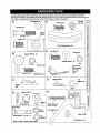
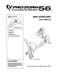
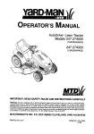
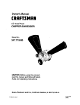
Lay the hardware pieces from the hardware pack on top of the figure here and you will have automatically soded these
aCCordingto the steps of the assembly procedure described later. (Only one unit of each hardware has been shown per group.
The number in parenthesis indicates the total number of the hardware needed in that group.)
A
Lock Washer (4)
E_
Hex Bolt (6)
Hex Bolt (2)
Nut (6)
'N
"--"
_/Flanged
/_
1/4-20 x .75
q
_;
1/4-20
m
/
5/16-18 x 1.75
h
Hex Bolt (2)
Handle
Tab (2)
,/t
NN
Chute Flange Keeper (3)
5/16-18 x .75
F
B
Cupped Washer (4)
:-_"ex
Bolt(2)
_)
Hex_, (2)
m
1/4-20 X .75"
Cup_pe
d Washer
(2)
G
i
1/4-20
m
Hex Nut (4)
Upper Chute
m
b
b
_5/16-18
_\ x 1,50
Carriage Bolt
(4)
(notshown
in actual
Crank
size) Bracket
'_/
m
G
(_
Helrp_
Hairpin Clip (1)
Flat
©7
]
Clip
3/8 I.D.
H
D
-_fi_ilrpln
Clip (2)
HIIIIIIIIIIIIIIII_,@
_
Flat Washer (2)
_
I
!
-
Ferrule
(1)
,1024x,375"
/F
3pare Part
"__
Lock
Nut (2)*
"Shear Bolt*(2)
5/16-18 x 1.5
Hex
Hot (2)*
*Used on auger; **Used on clutch lever
Turn Tr_r_////
//
_,/
_"
Cable Tie_ (2)
Rat Weld Nut (2)
Chute
Rear
Handte
Panel
, Left
Handles
Shift
Rod
Chute
Electric
Start Cord
Crank
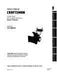
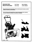
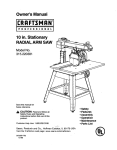
Figure I
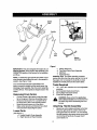
iMPORTANT: This unitis shippedwith engine oil, but
without gasoline, in the engine. After assembly, see
OPERATION section of this manLJalfor fuel selection
and fill-up.
NOTE: To determine right and left hand sides ofyour
snow thrower, stand behind the unitin the operator's
position. See Figure I inset,
Your snow thrower has been assembled at the
factory, except the handle and the handle panel, the
discharge chute assembly,the chute crank assembly
and the shiftrod. These parts are shipped loose in the
carton.
Removing From Carton
•
•
•
•
Cut the comers of the carton and lay the sides
fiat on the ground. Remove all packing inserts.
Remove all loose parts, For a complete list of
the looseparts, refer to the following section.
Move the snow thrower out of the carton.
Make certain all parts and literaturehave been
removedbefore discardingthe carton.
c. Electric Start Cord
d. Two-Piece Chute Crank Assembly
e. Shift Rod
f. Hardware Pack
Assembly Tips: For easier assembly purposes,
remove the chute from the carton and lay it on top of
the engine. Do not unwrap the chute tillyou have
installedthe handle panel and the clutchcables.
Tools Required
1.
2.
3.
4.
1/2", 7/16", 3/8" wrenchesor a set of adjustable
wrenches
Set of standard head screw drivers
Set of philipshead screw drivers
Funnel to fill up gasoline
wire
Is disconnected
and moved
away
from
WARNING:
Make certainthe
spark
plug
the spark plug before assemblingthe snow
thrower.
Attaching
•
Loose Parts
(See Figure 1.)
a. Handle Panel & Chute Assembly
b. Right Hand & Left Hand Handles
6
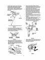
Handle Assembly
Stretchout controlcables and place on the floor.
Place the righthandle in positionwith the flat
side against the snow thrower. Youcan identify
the right handle by the traction drive control label
on it and the left handle by the auger clutch
control label on it.
Secure
bottomholeonthehandle
tothesnow
thrower
using5/16x .75"hexboltandlock
washer
from the hardware pack (groupA on
•
Attach handle panel to the handle with two
carriage bolts, cupped washers (cupped side
againstthe handle panel) and hex nutson each
side. See Figure 3. You willfind these fasteners
in groupB ofthe hardware pack. Aligncontourof
the carriage bolt head with the handle. Tighten
the hardware. Repeat on other side.
Align the hole on the curved part of the right
handle with the correspondinghole on the right
side of handle panel making sure that this end of
the handle isfirmly placed in the slot on the
handle panel. See Figure 3.
Inserta hex bolt, cupped washer and flange nut
from Group F of the hardware pack through
these holes as shown in Figure 3.Tighten to
secure, Do not attach the left side now.
page 5 ). Do nottightenat thistime. See Figure2.
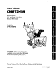
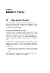
Lock Washer &
He]( Bolt (1-3/4")
•
•
Attaching Chute
Right Handle
•
Handle
Tab
Hex Bolt (.75")
Figure 2
•
•
•
•
Place the chute assembly over the chute
opening with the chute facing front of the unit.
NOTE: Make sure that the chute cables are
straightened while assembling the chute.
Place a handle tab, included in the hardware
pack (groupA ), over the upper hole in handle so
that the contourof the handle tab matches that
of the handle. See Figure 2.
Secure handle tab to the snow thrower using
hex bolt (5/16 x 1.75" long) and lock washer
from the same group in the hardware pack. Do
not tighten at this time.
Attach the left handle in the same manner. Do
not tighten at this time.
Place the handle panel in positionbetween the
handles so the ends of the curvedpart of the
handles go throughthe slots in the handle panel.
While placing the handle panel, make sure to
routechute and chute cable between the handle
and the panel keeping the cable on top of the
engine. Align the holes in the handle with the
holes on the two sides of the handle panel. See
Figure 3.
Handle
RightHandle
1
Panel
Place the chute flange keeper (flat side down)
beneath lip of chute assembly as shown in
Figure 4.You will find the chute flange keepers in
group E of the hardware pack.
Insert 1/4-20 x .75" hex bolt and flange nut
(group E of the hardware pack) up through chute
flange keeper and chute assembly as shown in
Figure 4. Do not tighten at this time. Rotate
chute to instal! all the flange keepers.
..xoo,t
Figure 4
After assembling all three chute flange keepers,
tighten, then back off 1/4 turn to allow easier
movement of the chute. Use (2) 7/16" wrenches.
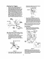
Attaching Chute Crank
•
/
Carriage Bolt
Washer
Figure 3
7
On the left side of the handle panel, place the
upper chute crank bracket on to the inside of the
handle panel support. Locate this bracket and
associatedhardware in group F of hardware
pack. See Figure 5.
Inserthexboltthroughthe upper chute crank
Place the other 3/8 ID flat washer (from the
same groupof hardware) on the end of the chute
crank and inserthairpin clip intoeye hole at the
end of the chute crank. See Figure 7.
Slide the upperchute crank through the plastic
bushingin the upper chute crank bracket and
then intothe lower chute crank. See Figure 8.
Align the holeson the two pieces of the chute
crank, and secure with hairpinclip from groupC
of the hardware pack.
Adjustthe chute bracket so that the spiral on the
chute crank fully engages the teeth on the chute
assembly.
Using a wrench, tightenthe hex boltand the hex
nut on the upper chute crank bracket.
Fully rotate the chute, usingthe chute crank, to
make sure that it moves freely. Tighten the nuts
on the lower chute crank bracket securely.
bracket, handle panel support, and upper left
handle. Secure the bracket using cupped
washer and hex nut. Make sure that the cupped
side of the washer is set against the contourof
the handle.
Handle Panel
Support*
\
l
"<
Hex Bolt
Crank Bracket
Tilt
Chute
Cables
Upper
Chute
Crank
\
* This part is already attached inside the handle panel
Figure 5
You may have to loosenthe carriage boltsand
hex lock nuts which secure the lower chute
crank bracket to the extension on the left side of
the chute assembly. See Figure 6.
Upper
Chute
Crank
Bracket
LowerChute
Crank
L
rrlage Bolt,
CrankBracket
Itex LockNut
Flgure 8
Figure 6
Slip the cables that runfrom the handle panel to
the chute intothe cable guide located on top of
the engine. See Figure 9.
Place one 3/8 ID flat washer (from group G of
the hardware pack) on the end of the chute
crank, then insertthe end of the crank intothe
eye hole in the plasticbushing in the chute crank
bracket. See Figure 7.
Cotter Pin
Cable Guide
Flat Washer
Chute Crank
Flat Rasher
Lower Chute /
Crank Bracl_t
Figure 9
Figure 7
8
Tightenallloose hardware on the handle
A
assembly in the followingorder-- firstthe hex
boltsat the bottomof the handle, then the
carriage bolts and lastlythe hex boltson the rear
of the handle panel.
Attaching
WARNING: There must not be any tension
on either clutchcable with the driveor auger
clutchgrip in the disengaged (up) position.
These clutchesare a safety feature. Do not
override their function by allowingtension
on eithercable withthe clutchesdisengaged.
Clutch Cables
The clutchcontrolcables are attached to the snow
thrower. If the cables ere attached to the top of the
engine with cable ties, cut the cable ties now. The Z
ends of the clutchcables are hooked intothe clutch
grips on each handle.
•
Ensure there is a hex jam nut threaded all the
way up the threaded portion ofthe Z fitting;
extras are supplied in the hardware pack. See
Figure 10.
•
Place the clutch grip in the raised (up) position.
Attaching Shift Rod
•
•
•
Z Fitting
Outer
of cut-out
\
•
Nut
Place the shift lever in the sixth (6) speed.
Place the bent end of the shiftrodintothe holein
the shiftarmassembly.See Figuret 1. Securewith
5/16 flatwasher and hairpinclipfromthe hardware
pack(groupD on page 5).
Start threading the ferrule (included in the same
groupin the hardware pack) ontothe otherend of
the shiftrod. It has to line up with the upper hole
in the shift lever (beneath the handle panel).
While aligningthe ferrule, push down on the shift
rod and the shift arm assembly as far as it willgo.
Once the ferrule slides intothe hole, turn it
counter-clockwiseone more ful!turn and insert it
in the hole in the shift lever.
Hex Jam
Shift
Lever
Nut
Chute Distance
Control
Drive
Clutch
Ferrule
Auger
Upper
Barrel
Shift
Lever
Clip
(Viewed from the underside of the control panel)
Figure 10
•
•
•
Rod
Swing the left auger up making sure the cable is
routed correctly in the cable rollerguides located
at the lower rear of the unit.
Hold the end of the cable at the barrel so the
ferrule turnsfreely withouttwisting the cable.
Thread the ferrule on to the Z fitting.You may
have to pull on the cable slightlyto relieve
tension. Keep the ferrule turning without twisting
the cable.
You willreach correctadjustmentwhen there is
minimalslack inthe cable but it isnot tight.Hold
the flats on the ferrule with pliersand tightenthe
jam nut againstthe ferrule.
Assembly
Clip
Figure 11
NOTE: It may be necessary topull the shiftlever out of
the sixth speed positionand move it towardsthe fifth
speed positio n until the ferrule slides into the hole
withoutforce.
Secure the ferrule to the shift lever with another
5/16 flat washer and hairpin clipfrom group D of
the hardware pack. See Figure 11.
Make certain to check for correctadjustment of
the shift rodas instructedin the Adjustment
sectionbefore operating the snow thrower.
CAUTION: Cables willbecome loose if you do not
tighten the jam nut.
9
Attaching Turn Triggers
hardware pack. Make sure to routethe cable tie
over the drive cable. See Figure 14.
Make sure that the right hand triggercable is
routed in front of the traction drive cable.
Feed thetriggercable up throughthe outersideof
the slotinthe handlepanel. Do notfeedthe cable
throughthe same side ofthe slotas theZ fitting.
Place the cable barrelfitting intothe holein the
trigger.You can findthe triggersand associated
hardware in groupH of the hardware pack (on
page 5). Pullon the cable and rotate it aroundthe
bottomof thetrigger,with the inner cable in the
slot,untilthecable end can be pushed intothe
triggerhousingand snappedtight. See Figure 12.
•
•
Figure 14
Secure the leftturn triggercable to the lower
handle using the othercable tie. Make sure to
route the cable tie below the auger drive cable
so that when the trigger cable is secured by the
cable tie, the auger drive cable is left outside the
cable tie.Trim excess ends from each cable tie.
Trigger
Assembly
Inner Cable
NOTE: The right side cable tie must be used to keep
cable from comingin contact with the moving shift
arm from the transmission.
Y
Barrel
Fitting
Lamp Wiring
Slot
•
thisend
Wrap the wire from the lamp downthe right
handle. Plugwire intothe aitemator lead wire
under thefuel tank. See Figure15.
Figure 12
Note: When the cable is installed correctly, it should
not be possibleto pull cable out of the trigger housing.
I
_
Hsn le
Place the rightturn trigger in position
underneath the right handle. Secure with screw
and weld nut from group H of the hardware
pack. See Figure 13. You will need a phillips
screwdriverfor tighteningthe screw. Repeat on
left side.
Turn
S_ot
,Trigger
Cable
Figure 15
IMPORTANT: Assemble your snow thrower, then
check the adjustmentsas instructedand make any
final adjustments necessary before operatingthe unit.
Failureto follow the instructionsmay cause damage
to the snow thrower.
Figure 13
•
Secure the right turn triggercable to the right
lower handle, usingcable tie provided in the
10
NOTE: Cables are out of adjustment if augers
continueto turn when auger clutchis released and/or
machine continuesto run when drive clutchis
released. For more details, refer to the Service and
Adjustment section.
Final Adjustments
Adjusting Auger Control
•
•
•
•
To check the adjustment of the auger control,
push forward the left hand clutchgrip untilthe
rubberbumper is compressed, There should be
slack in the clutchcable.
Release the clutchgrip.The cable should be
straight. Make certain you can depress the
auger controlgrip against the left handle
completely.
If adjustment is necessary, loosen the hex jam
nut and thread the cable in (for less slack) or out
(for more slack),
Recheck the adjustment. Tighten the jam nut
against the cable when correctadjustment is
reached.
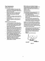
Adjusting Skid Shoe
The space between the shave plate and the ground
can be changed by adjustingthe skid shoe.
•
Return weight transferlever to normal position
before adjustingskid shoes.
•
For close snow removal, adjust skid shoes
higher to minimizegap between the shave plate
and the ground.
•
For snow removalfrom uneven ground like
gravel, adjustskid shoes downwardto create
sufficientclearance between the bottomedge of
the shave plate and the ground. See Figure 16.
Adjusting Traction Drive Control
•
•
•
•
•
•
NOTE: It is not recommended that you operate this
snow thrower on gravel as loose gravel can be easily
picked up and thrownby the auger causing an injury
or damage to the snow thrower. However, if you do
have to use the snow throweron gravel, put the weight
transfer lever to transport position.
To check the adjustment of the traction drive
controland shift lever, move the weight transfer
lever to the transportposition (shownin Figure
18 on page 13) and the shift lever all the way
forward to sixth (6) position.
With the tractiondrive control released, pull the
triggersup to the handle and then pushthe snow
thrower forward to checkthat the tracks turn.
Squeeze tractiondrivecontrolagainstthe handle
and pullthe starter.The tracksshouldturn.
Now release the tractiondrive controland pull
the starter again. The unitshould not move.
Before proceedingwith adjustment, make sure
that the spark plug is disconnected.
If the traction drive controlneeds adjustment,
loosen the jam nut on the traction drive cable
and thread the cable one turn. Recheck
•
•
Adjust skid shoes by loosening the four hex nuts
and carriage bolts and moving skid shoes to
desired position. Make certain the entire bottom
surface of skid shoe is against the ground to
avoid uneven wear on the skid shoes. See
Figure 16.
Retighten nuts and bolts securely.
adjustment and repeat as necessary.
Tighten the jam nut to secure the cable when
correctadjustment is reached.
Skid Shoe
_
_HeXNa_t"
Figure 16
11
Bolt
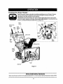
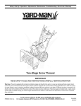
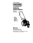
Knowing Your Snow Thrower
Read this owner's manual and safety rules before operating your snow thrower. Compare
with your snow thrower to familiarize yourselfwith the location of various controls and
adjustments.Save this manual for future reference.
The operation of any snow thrower can resultin foreign objectsbeing thrown intothe eyes,
which can resultin severe eye damage. Always wear safety glasses for operating the snow
thrower, or while performingany adjustments or repairs on it.
Oil
Auger
Control
Spark
Choke
Fuel
Fill
\
Control
Traction Drive
Shift Distance
Chute
Lever Lever
Fuel
Chute Crank
Tank
Starter
Handle
Throttle
Right
Turn
Recoil
Starter
Trigger
DischargeChute
Weight
Transfer
Lever
Track
Auger
Skid Shoe
Figure 17
Meets ANSI Safety Standards
Sears snow throwers conformto the safety standardsB71,3 of the American National Standards Institute (ANSI),
12
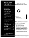
Operating Controls
Weight Transfer Lever
(See Figure 17.)
The weighttransfer lever is locatedon the rightside of
the snow thrower and is used to select the positionof
the housingand the method oftrack operation. See
Figure 18. Move the lever to the right,then forward or
backward to one of the three positions.
Chute Crank
The chute crank is located on the left side of the snow
thrower. To change the direction in which snow is
thrown, turn chute crank as follows:
turn clockwise to discharge to the left;
turn counterclockwiseto discharge to the right.
Normal
Snow
Packed
Snow
Chute Distance Control
The distance that snow is thrown can be adjusted by
adjusting the angle of the chute assembly. Push the
chute distance control lever forward to move the
upper chute down and decrease the distance. Pull the
lever back toward the rear to move the upper chute
up and increase the distance.
\
,/
Transport
Left And Right Turn Trigger
The left and rightturntriggers are located on the
underside of the handles and are used to assist in
steering your snow thrower. Squeeze the rightturn
trigger when turning right,squeeze the leftturntrigger
when turningleft. Operate your snow thrower in open
areas untilyou become familiar with these controls.
Figure 18
Shift Lever
a. Transport--Raises the front end of the
snow thrower for easy transport. Using
propercaution, this positionmay also be
used on many gravel drivewaysto clear
snow while leaving gravel undisturbed.
b. Normal Snow--Allows the tracks to be
suspended independently for continuous
ground contact.
c. Packed Snow.--Locksthe front end of the
snow thrower down to the ground for hardpacked or icysnow conditions.
The shift lever is located in the center of the handle
panel. It may be moved into one of eight positions:
a. Forward--oneofsixspoeds;po,v_onone(1)
is the slowest and position six (6) is the
fastest.
b. Reverse--two reverse (R) speeds; R2 is
faster.
Use the shift lever to determine ground speed. Do not
shift to different speed while the unit is moving.
Auger Control
Throttle Control
The auger controlis located on the left handle.
Squeeze the auger controlagainst the handle to
engage the augers; release to disengage the augers.
(Tractiondrive controlmust also be released.)
The throttle controlis located on the engine. It
regulates the speed of the engine.
Safety Ignition Switch
Traction Drive Control
The ignitionkey must be inserted intothe switchfor
the unitto start. Remove the ignitionkey when the
snow thrower is not in use.
The traction drive controlis located on the right
handle. Squeeze the traction drive controlto engage
the track drive; release to stop.
To Stop The Snow Thrower
This same lever also locks the auger control so
that you can turn the chute crank without interrupting
the snow throwing process. If the auger controlis
engaged with the traction drive controlengaged, you
can release the auger control (on the left handle) and
the augers will remainengaged. Release the traction
drivecontrolto stop both the augers and the track
drive. (Auger controlmust also be released).
•
•
•
13
To stop the track, release the traction drive lever
of the snow thrower.
To stopthrowingsnow,releasethe augerdrive
lever and the drive lever if engaged.
To stop the engine, pushthe throttle control
lever to OFF and pull out the ignitionkey. Do not
turn key.
Before Starting Engine
Never use engine or carburetor cleaner products in
the fuel tank or permanent damage may occur.
Fill Gas
&
To Start Engine
WARNING: Gasoline isflammableand cautionmustbe used when handling or storingit.
&
Do not fillfuel tank whilethe snow thrower is
running,when it is hot or when it is in an
enclosed area.
Keep your snow thrower away from any
open flame or an electricalspark and do not
smoke while filling the fuel tank.
WARNING:
Be sure no one other than
the operator is standingnear the snow
throwerwhile starting or operating. Do not
operate this snow thrower unless the
dischargechute assembly has been
properly installedand issecured.
A. Electric Starter
Never fill the fuel tank completely. Fill the
tank to within 1/4"-1/2" from the top to
provide space for expansion of fuel.
Connect spark
wire
Always fill the fuel tank outdoors and use a
funnel or spoutto prevent spilling.
Make sure to wipe off any spilledfuel before
startingthe engine.
•
•
•
•
Insert key_
Store gasoline in a clean, approved container
and keep the cap in place on the container.
Make sure that the container from which you
pour the gasoline is clean and free from rust or
other foreign particles.
Fill fuel tank with clean, fresh, unleaded grade
automotive gasoline.
At the end of the job, empty the fuel tank ifthe
snow thrower is not going to be used for 30 days
or longer. See storage instructions on page 24
of this manual.
starter
CAUTION: Experience indicatesthat alcohol
blended fuels (called gasohol) or those using ethanol or methanol can attract moisture which leads to
separation and formationof acids during storage.
Figure 19
For locationof all the engine controlsreferred to in
this section, see Figure 19.
Acidic gas can damage the fuel system of an engine
while in storage.
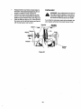
Before starting, make sure that the engine has sufficient oil. The snow thrower engine is equipped with a
120 volt A.C. electric starter and recoil starter. The
electricstarter is equipped with a three-wire power
cord and plug and is designed to operate on 120 volt
AC householdcurrent,Foll_vall instructions
carefully.
To avoidengine problems,the fuel system shouldbe
emptiedbeforestoragefor 30 days or longer. Drain the
gas tank, start the engine and let it run untilthe fuel
linesand carburetor are empty.Use fresh fuel nextseason. See storageInstructionsfor additionalinformation.
_
!Snow
Thrower
Spark
Plug
wire
Drive
Levers
button
Move
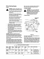
Starting Instructions
at a glance
Throttle
control
Ignition
Key
Choke
Power
Cord
Connect
to source
Electric
Starter
Connect Release
Move to
FAST
Push to
snap in
Move to
FULL
Recoil
Starter
IConnect Release
Moveto
FAST
Push to
snap in
Move to
FULL
14
Primer
Pnme
Starter
After starting
Push
button
t. Release button
2. Move Choke to Off
3. Disconnect cord
IPull
handle
t. Release handle
2. Move Choke to Off.
ColdStart
Operate the engine at full throttle (FAST) when
throwing snow.
NOTE:ff the unit shows any sign of motion
(drive or
augers) with the clutch grips disengaged, shut the
engine off immediately. Readjust as instructedin the
"FinalAdjustments"section on page 11.
Warm Start
If restarting a warm engine after a shut down,
rotate choke to OFF insteadof FULL and press
the starter button.
WARNING: The electric starter must be properly
grounded at all times to avoid possibility of electric
shock which may injurethe operator.
•
Determine whether your house wiring is a threewire groundedsystem. Ask a licensed
electricianif you are not certain.
,_
•
•
•
•
•
•
•
•
•
•
B. Recoil Starter
Make sure that the engine has sufficient oil and the
auger drive and the traction drive levers are released.
•
Move throttle control to FAST position.
•
Push key into the ignitionslot so that it snaps
into place. Do not turn key. Remove plastic bag
and keep the second key in a safe place.
•
Rotate choke control to FULL choke position.
•
Push the primer button while covering the vent
hole. Removeyourfingerfromthe primerbetween
primes. Do not prime if temperature is above
50° F; primetwo timesbe{ween50° F and 15oF;
and primefourtimesbelow15° F.
•
Pull the starter handle rapidly. Do not allowthe
handle to snap back, but allow itto rewind slowly
while keeping a firm hold on the starter handle.
•
As the engine warms up and begins to operate
evenly, rotate the choke knobslowlyto OFF
position.If the engine falters, returnto FULL
choke, then slowlymove to OFF choke position.
•
Allow the engine to warm up for a few minutes
because the engine will not develop full power
untilit reaches operating temperature.
•
Operate the eng!ne at fullthrottle (FAST) when
throwing snow.
not
a three-wiregrounded
system,do notuse
WARNING:
Ifyour housewiringsystem
is
this electricstarterunder any conditions.
If your house wiringsystem is grounded and a
thrae-hole receptacle is not available at the point
the snow thrower starter will normallybe used,
one should be installed by a licensed electrician.
When connecting the power cord, always
connect cord to starter on engine first, then the
other end into a three-hole grounded receptacle.
When disconnecting the power cord, always
unplug the end from the three-hole, grounded
receptacle first.
Attach spark plug wire to spark plug.
Make sure that the auger drive and the traction
drive levers are in the disengaged RELEASED
position.
Move throttle controllever to FAST position.
Remove the keys from the plasticbag. Push key
intothe ignitionslot. Make sure itsnaps into
place. Do not tum key. Save the second key.
Rotate the choke knobto FULL choke position.
Connect power cord to switchbox on engine.
Plugthe other end of the power cord into a
three-hole, grounded 120 volt A.C. receptacle.
Warm Start
•
If restartinga warm engine after a temporary
shut down, rotate choke to OFF insteadof FULL
and do not prime. Press the starter button.
Frozen Recoil Starter
startingthe engine
electricstarter,
WARNING:
Do notwith
use an
primer
while
If the starter is frozen and will not turn the engine,
proceed as follows:
•
Pull as much rope out of the starter as possible.
•
Release the starter handle and let it snap back
against the starter.
•
If the engine still fails to start, repeat the first two
steps. If continued attempts do not free starter,
follow the electric starter procedures to start.
•
Avoid possible freezing of recoil starter and the
engine controls.
Push down on the starter button until the engine
starts. Do notcrank for more than 10 secondsat
a time. This electric starter is thermally
protected. If overheated, itwill stop
automaticallyand can be restarted only when it
has cooled to a safe temperature (a wait of
about 5 to 10 minutes is required).
When the engine starts, release the starter
button and slowlyrotate the choke to OFF
position. If the engine falters, rotate the choke to
FULL and then gradually to OFF.
Disconnect the power cord from the receptacle
first and then from the switch box on the engine.
Allow the engine to warm up for a few minutes
because the engine will not develop full power
until it reaches operating temperature.
Operating
Snow Thrower
To Engage Drive
With the engine running near top speed, move
shift lever to one of six FORWARD positions or
two REVERSE positions.Select a speed
appropriatefor the snow conditionsthat exist.
15
Use slowerspeeds untilyou are familiar with the
operation of the snow thrower.
Squeeze the traction driveclutchgrip againstthe
right handle and the snow thrower will move.
Release it and the drive motionwill stop.
•
Operating Tips
NOTE: AIIow the engine to warm up for a few minutes
as the engine willnot develop fullpower untilff
reaches operating temperature.
To Engage Augers
To engage augers and start snow throwing,
squeeze the left hand auger clutchgrip against
the lefthandle. Release to stop augers.
While the auger control is engaged, squeeze the
tractiondrive controlto move, release to stop. Do
not shift speeds whilethe drive is engaged.
surroundingareas
may exceed
150 ° F.and
Avoid
Warning: The temperature
of muffler
these areas.
•
NOTE: This same lever also locks the auger control so
you can turn the chute crank without interrupting the
snow throwing process.
•
•
,_
•
•
Release the auger control;the interlock
mechanismshould keep the auger control
engaged untilthe traction drive controlis
released.
Release the traction drivecontrolto stop both the
augers and the track drive.
•
must be released.
WARNING: To stop the auger, both levers
CAUTION: Check the area to be cleared for foreign
objects. Remove, if any.
•
•
For most efficientsnow removal, remove snow
immediatelyafter it falls.
Discharge snow downwind whenever possible.
Slightlyoverlap each previousswath,
Set the skidshoes 1/4"belew the scraperbarfor
normalusage.The skidshoes may be adjusted
upwardfor hard-packedsnow.Adjustskidshoes
downwardwhen usingon gravel or crushedrock.
Clean the snowthrower thoroughly aftereach use.
Before Stopping
•
To Throw Snow
•
After the area is cleared, stop the snow thrower
following instructionsgiven below.
Move weight transfer lever to the right, then
backward or forward to the desired position.
Start the engine following Starting Instructions.
Rotate the discharge chute to the desired
direction,away from bystandersand/or buildings.
Move the chute distance controlforward or
backward to adjustthe distance the snow is to be
thrown.
Select the speed according to the snow
condition.
Run engine for a few minutesto help dry offany
moistureon engine.
To avoidpossible freeze.up of the starter, follow
these steps:
Recoil Starter
a. With the engine running,pullthe starter rope
with a rapid, continuousfullarm stroke three
or fourtimes.
Electric Starter
a. Connect power cord to switch box, then to
120 Volt AC receptacle.
b. While the engine is running,push the starter
buttonand spinthe starter for several
seconds.
c. Disconnectpower cord from the receptacle
first,then from the snow thrower.
NOTE: The unusual sound from pulling the starter
rope in the case of the recoil starter, or from spinning
the starter in the case of the electricstarter, willnot
harm the engine.
CAUTION: Never move the shift lever withoutfirst
releasing the drive clutch.
To Stop The Snow Thrower
Engage the auger controland traction drive
controllevers following the preceding
instructions.
The interlock feature will allow you to remove
your left hand from the auger controllever.
When clearingthe first pass throughthe snow,
controlthe tractionspeed of the snow thrower
accordingto the depth and conditionof snow.
To turn the unitleft, squeeze left trigger;to turn
right,squeeze righttrigger.
On each succeeding pass, readjust the chute
deflector to the desired positionand slightly
overlap the previouslycleared path.
•
•
•
16
To stop the track, release the tractiondrive lever
on the snow thrower.
To stopthrowing snow,releaseaugerdrivelever
and drivelever, if engaged.
To stop the engine, push throttlecontrollever to
OFF and pull out the ignitionkey. Do not turnkey.
General Recommendations
•
Always observe safety rules when performing
any maintenance.
The warranty on this snow thrower does not
cover itemsthat have been subjected to
operator abuse or negligence. To receive full
value from the warranty, operator must maintain
the snow thrower as instructedin this manual.
Some adjustments will have to be made
periodicallyto maintain your unit properly.
All adjustments in the Service and Adjustments
section of this manual should be checked at
least once each season.
Follow the maintenance schedule given below.
Periodically check all fasteners and make sure
these are tight.
•
&
WARNING: Always stop the engine and
disconnect the spark plug wire before
performingany maintenance or
adjustments.
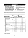
Customer Responsibilities
MAINTENANCE SCHEDULE
._oJ
_
_
_
Lubricate pivot points
• _
__o
_ SERVICE DATES*
<_
Clean snow thrower
0
a.
Clean shave plate
Clean skid shoes
'_
Check V-belts
Check friction wheel
rubber
Check engine oil
'_
I
_Z
Z
g.l
Change engine oil
_:_
<_
Check spark plug
'_
Check muffler
Emptyfuel system
'_
* Fill in dates as you complete regular service
Check; service if needed
17
Lubrication
Bearings
For a view of the lubricationpoints on the snow
thrower, see Figure 20.
Once a season lubricatethe auger bearingsand
the bearingson the side of the frame with light
oil. See lubricationchart below.
Sprocket Shaft
•
Lubricatethe sprocketshaft with grease at least
oncea seasonor after every25 hoursof
operation.
Check V-belts
Shifting Mechanism
Follow instructionsbelow to check the conditionof
the drive belts every 50 hours of operation.
•
Remove the plasticbelt cover on the front of the
engine by removingtwo self-tapping screws.
•
Visually inspectfor frayed, cracked, or
excessively wornout belts.
•
Check Friction Wheel
IMPORTANT: Keep all grease and oiloff of the
friction wheel and the drive plate.
Lubricatethe shiftingmechanism and pivot
points on the shift rodwith engine oilat least
once a season or after every 25 hours of
operation,
Traction Drive Control
•
Lubricate cams on the ends of the controlrods
which interlockthe tractiondrive and auger
controlsat least once a season or every 25
hoursof operation with grease. The cams can be
accessedbeneaththe handle panel,
Gear Case
The gear case is lubricatedwith grease at the
factory and does not require checking. If
disassembledfor any reason, lubricatewith two
ounces of Shell Alvania grease.
Follow the instructionsbelow to check the conditionof
the friction wheel rubber every 25 hours of operation.
•
Remove the four self-tapping screws from the
frame cover underneath the snow thrower.
•
Visually inspect the friction wheel rubber for
excessive wear, cracks, or loose fit on the
friction wheel drive hub.
•
Also engage traction drive control and check if
the friction wheel is making contact with the
friction plate.
•
If it does not make contact, adjust the traction
drive cable following adjustment instructions.
Recheck the friction wheel
•
Replace friction wheel rubber if necessary.
Refer to instructionson page 22.
LUBE
Figure 20: Lubrication Chart
18
•
Engine Maintenance
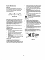
Engine Oil
•
Only use high quality detergent oil rated with API
service classification SF, SG or SH. Select the oil's
SAE viscositygrade according to the expected
operating temperature.
colder.,_---32
°
warmer
•
|
5W30 '9[
I
_'-_ SAE30
Drain oil while engine is warm. Remove oil drain
cap located at the bottomof the recoil starter of
the engine. Catch oil in a suitable container.
When engine is drainedof all oil, replace drain
plug securely.
Remove the dipstick from the oil till tube. For
locationof the oil fill tube, see Figure 17 inset.
Pour fresh oil slowlythroughthe tube. Replace
dipstick.
Check and make sure that the oil level is up to
the FULL mark on the dipstick.
I
Viscosity Chart
WARNING:
muffler
and
nearby
areas Temperature
may exceed of
150°
F (65°C).
Avoid these areas.
Spark Plug
NOTE: Although multi-viscosity oils (5W30, 10W30
etc.) improve startingin cold weather, these multiviscosityoils willresult in increased oil consumption
when used above 32°F. Check your snow thrower's
engine oillevel more frequentlyto avoidpossible
engine damage from runninglow on oil.
•
•
•
•
Refer to the viscosity chart for proper selection of
engine oil.
•
Checking Oil Level
IMPORTANT: Before operating the snow thrower,
check the oil level
•
•
•
•
Clean area aroundthe spark plug base.
Remove and inspect the spark plug.
Replace the spark plug if electrodes are pitted,
burned, orthe porcelain is cracked. See Figure21.
Clean the spark plug and reset the gap to 0.030"
at least once a season or every 50 hours of
operation. See Figure 21.
Spark plug replacement is recommended at the
start of each season. Refer to engine parts list
for correct spark plug type.
NOTE: Do not sandblastspark plug. Spark plug
shouldbe cleaned by scrapingor wire brushing and
washing with a commercial solvent.
With engine on level ground, the oil must be to
FULL mark on dipstick.
Stop engine and wait several minutes before
checking oil level. Remove oil fill cap and
dipstick.
Wipe dipstick clean, insert it into oil fill hole and
tighten securely.
Remove dipstick and check. If oil is not up to the
FULL mark on dipstick, add 5W30 oil.
Changing Oil
Figure 21
Change engine oilafter the firsttwo hours of
operation and every 25 hours thereafter.
In order to do that you willhave to first drain the spent
engine oil from the engine and then refillwith fresh oil.
19
A
WARNING: Always stop the engine, disconnect spark plug wireand move it away
from the spark plug before performingany
adjustmentsor repairs,
NOTE: ff you placed plastic under the gas cap, be
certain to remove it,
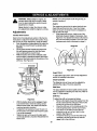
Augers
The augers are secured to the spiral shaft with two
shear boltsand hex lock nuts. If you hit a foreign
object or ice jam, the snow thrower is designed so
that the boltswill shear.
•
If the augers will not turn, check to see ifthe
boltshave sheared. Replace ifnecessary. See
Figure23. Two replacement shear boltsand hex
lock nuts have been provided in Group D of the
hardware pack which is illustratedon page 5.
Never attempt to clean the chute or make
any adjustmentswhile the engine is running.
Adjustments
Traction Drive Control
Refer to the Final Adjustmentsection of the Set-Up
Instructionsto adjust the traction drive control. If you
are not sure of proper adjustment, check as follows.
•
Drain the gasolineor place plasticfilm under the
gas cap if the snow thrower has already been
operated.
•
Tip the snow thrower forward and remove the
four self-tapping screwsthat hold the frame
cover underneaththe snow thrower.
With the tractiondrive controlreleased, make
sure that there is clearance between the friction
wheel and the friction plate in all positionsof the
shift lever. See Figure22.
"_l_
Sproc.e,
I I
Shear Bolt
\
Figure 23
Drive
Auger Clutch
To adjustthe auger clutch, refer to Final Adjustment
sectionof Assembly Instructions,
Chute Assembly
• IILIIIi._,i-II
The distance snow is thrown can be adjusted by
adjustingthe angle of the chute assembly,
,r,ct,on--...lli-tlLltL
° Jill I
°,' Lon
Skid Shoe
The space between the shave plate and the ground
can be adjusted by adjusting the skid shoe. Refer to
page 11 of this manual.
Shift Rod
To adjust the shift rod, proceed as follows.
•
Remove the hairpin clipand flat washer from the
ferrule underneath the shiftpanel. Remove the
ferrule from the hole in the shift lever.
•
Place the shift lever on the handle panel in the
sixth (6) speed position(all the way forward).
•
Push down on the shift rod (and shift arm
assembly) as far as it will go. Hold it in this
position.See Figure 24.
•
Thread the ferrule up or downthe shift rod as
necessary untilthe ferrule lines up with the
upper hole in the shift lever.
Figure 22
With the tractiondrive controlengaged, make
sure that the frictionwheel is makingcontact
with the friction plate, Also make sure that the
overtravel springis stretched.
If adjustment is necessary, loosen the jam nut
on the traction drivecable and thread the cable
in or out as necessary.
Tighten the jam nut to secure the cable when
correct adjustment is reached. Reassemble the
frame cover.
20
Auger Drive Belts
Shift
Lever
•
Chute Distance
Control
Drive
Clutch
Auger
•
Disconnectthe chute crank at the chute
assembly by removing the cotter pin and the flat
washer.
Remove the plasticbelt cover on the frontof the
engine by removingtwoself-tapping screws.
See Figure 25,
Upper
Self-Tapping
Shift
Lever
Clip
Flat
Washer
Spring
Washer
Rod
Cover
Assembly
Clip
Flat
Washer
Figure 24
•
•
\
Insertthe ferrule intothe upper hole in the Shift
lever from the right side when adjustment is
correct. Secure with the fiat washer and the
hairpinclip that you had earlier removed. See
Figure24.
Check for correctadjustment of the traction
drive controlas instructedin the Final
Adjustment section.
Self-Tapping
Screw
Figure 25
Unthread the bottom of the auger cable from the
top ofthe cable, leavingthe hex nut in place.
Removethe sixlockwashersand hex nutswhich
attachthe augerhousing assemblyto the frame.
See Figure26. (Onlytwopairsof lockwashersand
hex nutsare shownin thefigure.)
Service
Shave Plate And Skid Shoes
The shave plate and skid shoes on the bottom of the
snow thrower are subject to wear. They should be
checked periodically and replaced when necessary.
•
To remove skid shoes, remove the two carriage
bolts, beUevillewashers and hex nuts (on each
side) whichattach them to the snow thrower.
•
Reassemblenewskid shoeswiththe hardware
earlierremoved,Make sure to insertthecupped
side ofthe washer againstthe skidshoe sothatthe
skidshoe isadjusted to be level,
•
To remove shave plate, remove the carriage
bolts, bellevillewashers and hex nuts which
attach it to the snow thrower housing,
Reassemble new shave plate, making sure
heads of the carriage bolts are to the inside of
the housing.Tighten securely.
Lock Washer
and Hex Nut
Figure 26
Separate the housingfrom the frame assembly
by standingin the operating positionand lifting
up on the handles. The frame and housingwill
separate and the rear auger drive belt willcome
off the pulleys.
Belt Removal and Replacement
from
the spark
plug and ground
it. plugwire
WARNING:
Disconnect
the spark
21
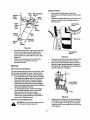
•
Back out the stop bolt untilthe supportbracket
drops on the auger pulley, See Figure 28.
Slip belt between friction wheel and friction disc
plate and remove the belt. See Figure 28.
Reassemble with new drive belt.
•
Drive Belt
•
NOTE: The supportbracket must rest on thestop bolt
after thenew belt has been assembled. See Figure 28.
Friction Wheel Rubber
The rubberon the friction wheel is subjectto wear and
shouldbe checked after the first 25 hours of operation
and periodicallythereafter. Replace the friction wheel
rubber ifany signsof wear or crackingare found.
•
Drain the gasolinefrom the snow thrower,or
place a piece of plasticunder the gas cap.
•
Tip the snow thrower up and forward, so that it
restson the housing.
•
Remove four screws from the frame cover
underneath the snow thrower (Figure 25).
•
Using a 7/8" wrench to hold the shaft, loosen,
but do not completelyremove, the hex bolt and
bell washer from the leftend of the shaft. See
Figure 29.
Figure 27
To remove the front auger drive belt, push the
idler pulley to the leftand liftfront auger drive
belt from the front auger pulley. See Figure27.
Replace both auger drive belts by following the
preceding instructions.
NOTE: When reassembling the two halves of the unit,
make sure that the auger drive cable is routed
throughthe cable roller guide.
Drive Belt
•
•
•
•
•
Remove the plasticbelt cover on the front of the
engine by removingthe two self-tappingscrews.
See Figure 25.
Drain the gasoline from the snow thrower, or
place a piece of plasticunder the gas cap.
Tip the snow thrower up and forward so that it
rests on the auger housing,
Remove four self-tappingscrewsfrom the frame
cover underneath the snow thrower.
Pullingthe idler pulley upward, rollthe belt off
the idler pulley and the engine pulley and lift belt
off fdction wheel disc. See Figure 28.
Friction
Wheel Disc
Friction
Wheel
Remove
belt
here
Figure 29
•
•
•
•
Support
Bracket
Figure 28
22
Move the weight transfer lever to the packed
snow position.Refer to Figure 18.
Lightlytap the head of the boltto dislodgethe
ball bearing from the rightside of the frame; then
remove the hex boltand the bellwasher from left
end of the shaft.
Slidingthe shaft to theTight, remove the spacer,
the sprocketand the friction wheel assembly
from the shaft. See Figure30.
Remove the six screwsfrom the friction wheel
assembly (three from each side). Remove the
friction wheel rubber from between the friction
wheel plate.
•
Reassemble
thenewfrictionwheelrubberto
thefrictionwheelassembly
tightening
thesix
screwsinrotation
andwithequalforce.
•
Positionthe frictionwheel assembly up onto
the pin of the shift rod assembly and slide the
shaft through the friction wheel. See Figure 30.
Slide the shaft intothe hex I.D. of the sprocket,
the spacer and the leftball bearing and secure
with the bell washer and hex bolt.
•
Carburetor
A
WARNING: If any adjustmentsare made to
the engine whilethe engine is running(e.g.
carburetor), keep clear of all movingparts.
Be careful of heated surfaces and muffler.
If you thinkthe carburetor needs to be adjusted, see
your nearest authorizedTecumseh Service Outlet.
Shift Rod
ly
Washer
\
Friction
Wheel
Figure 30
23
&
If your snow thrower is leftunused for 30 days or
longer, it needs to be prepared for storage. Also, at
the end of the snow season, you should follow the
same set of instructionsend store the snow thrower
properly for the off-season. Proper storage ensures
longer life of the snow thrower.
Fuel leftin engine duringwarm weather
deteriorates and will cause serious starting
problems,
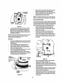
Preparing Engine
Run the engine untilthe fuel tank is empty and it
stops due to lack of fuel.
Drain carburetor by pressing upwardon bowl
drain, located below the carburetor cover. See
Figure 31.
WARNING: Never store snow thrower with
fuel in tank indoors or in poorlyventilated
areas, where fuel fumes may reach an open
flame, spark or pilotlight as on a furnace,
water heater, clothesdryer or gas
appliance.
A
WARNING: Drain fuel into approved
containeroutdoors,away from any open
flame. Be certainengine is cool. Do not
smoke.
&
It is important to prevent gum depositsfrom
forming in essential fuel system parts of the
engine such as the carburetor, fuel filter,
fuel hose or tank during storage.
Also experience indicates that alcohol
blended fuels (called gasohol or using
ethanol or methanol) can attract moisture
which leads to separation and formation of
acids during storage. Acidic gas can
damage the fuel system of an engine while
in storage.
To avoid engine problems, the fuel system should be
emptied before storagefor 30 days or longer. Follow
these instructionsto prepare your snow thrower for
storage:
•
Remove all gasolinefrom the carburetor and the
fuel tank to prevent gum deposits from forming
on these parts and causing possible malfunction
of the engine.
WARNING: Do not drain carburetor if using
fuel stabilizer.Never use engirle or
carburetorcleaning productsin the fuel tank
or permanent damage may occur.
NOTE: Fuel stabilizer (such as STA-BIL) is an
acceptable alternative in minimizing the formationof
fuel gum depositsduring storage. Add stabilizerto
gasoline in fuel tank or storage container. Always
followmix ratio found on stabilizer container. Run
engine at least 10 minutesafter addingstabilizer to
allow it to reach the carburetor.Do not drain
carburetor ff using fuel stabilizer.
Remove the spark plug and pour one (1) ounce
of engine oil through the spark plughole intothe
cylinder. Place a rag over the hole. Crank the
engine several times to distribute the oil.
Replace spark plug.
Preparing Snow Thrower
•
Carburetor
\
•
Bowl
Drain
Figure 31
24
When storingthe snow thrower in an
unventilatedor metal storage shed, care should
be taken to rustproofthe equipment. Using a
light oilor silicone, coat the equipment,
especially any chains, springs,bearings and
cables.
Remove all dirt from exterior of engine and
equipment.
Followlubricationrecommendationson
page 18.
Store in a clean, dry area.
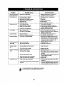
Problem
Possible Cause
Shift
lever
notlocking1, Shiftrodoutofadjustment
Corrective
1. Remove washer and pin. Turn ferrule
clockwiseone turn and reinstall,
intothesixthspeed
Enginefailstostart
1.
2.
3.
4.
5.
6.
Engine runs erratic.
1. Unit running on choke
2. Blocked fuel line or stale fuel
3. Water or dirt in fuel system.
Action
Fuel tank empty, or stale fuel
Fuel shut-oft valve closed
Ignition key not in switch or engine
Spark plug wire disconnected
Blocked fuel line
Faulty spark plug
1.
2.
3.
4.
5.
6.
Filltank with clean, fresh gasoline.
Open valve.
Insert key.
Connect spark plug wire.
Clean fuel line.
Clean, adjustgap or replace.
1. Turn choke to offposition.
2. Clean fuel line, fill tank with fresh fuel.
3. Drain carburetorfollowing instructionson
page 24, Refill with fresh fuel.
4. Contact Sears service center.
4. Carburetor out of adjustment
Lossof power
1. Spark plug wire loose
2. Gas cap vent hole plugged
1. Connect and tighten spark plug wire.
2. Remove ice and snow from cap, Make sure
that the vent hole is clear,
Engineoverheats
1. Engine oil level low.
2. Carburetor notadjusted properly
1. Fill crankcase with proper engine oil
2. Contact Sears service center.
Excessivevibration
1. Loose parts or auger damaged
1. Stop engine immediatelyand disconnect
spark plugwire. Tighten all nuts and bolts.
Check for the sourceof vibration. Make all
neceseePl repairs. If vibrationpersists,
contact Sears service center.
Hardto shiftspeed,or 1. Shift red not adjusted
will notshift
2. Hex sha_lnot lubricated
1. Readjust shift red.
2. Lubricate sprocket shaft.
Unitfails to propel
itself
1. Incorrectadjustment of drive clutch
1. Adjust drive clutch.
2. Ddve belt loose or damaged
2. Replace drive belt.
Unitfails to discharge 1. Auger shear bolt broken
snow
2. Discharge chute clogged
3, Foreignobject lodgedin auger.'
4. Auger drive clutchcable not adjusted.
5. Auger drive beltloose or damaged.
Trackdoes notturn
1. Track control cable not inserted.
2, Lowercable bracket not fullypositionedagainst
gear box.
1. Replace shear bolt.
2. Stop engine, disconnectspark plug wire and
clean discharge chute and inside of auger
housing.
3. Stop engine, disconnectspark plug wire and
remove object from auger.
4. Adjust propady.
5. Replace belt.
1. Insert the cable completely intothe trigger
assembly.
2. Loosentwo self-tappingscrews on each slot
of bracket. Retighten making sure that the
bolt is completely at the bottom of the slot.
please contact your nearest SEARS service center.
For repairs bey°nd the min°r adjustments listed above'
25
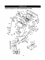
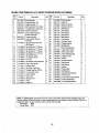
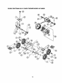
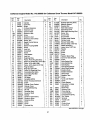
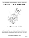
SEARS CRAFTSMAN
9.0 H.P. SNOW THROWER
26
MODEL 247.888550
SEARS CRAFTSMAN
Key
No.
9.0 H.P. SNOW THROWER
Part No.
Description
KeY
No,
Qty,
MODEL 247.888550
Part No.
Description
Qty.
1
629-0058
Harness for Headlight
1
40
736-0509
2
684-0008A0637
Shift Arm Assembly
1
41
43
737-0133
746-0896
Special Washer
Grease
Chute DeflectorControlCable
2
1
3
4
684-0053
684-0066
Chute Crank Assembly
Hardware Pack*
1
6
684-0102
Handle Panel Assembly w/
Tilt
1
44
45
46
746-0901
747-0798A
747-0877
Chute Deflector Cable w/Clip
Shift Rod
Cam Rod
1
1
2
684-0111
Handle Assembly
Engagement (L.H.)
Handle Assembly
Engagement (R.H.)
Carriage Bolt5/16-18 x 1.50
Hex Bolt5/16-18 x 1.5
1
47
48
49
748-0362
748-0363
749-0908A
Cam Handle Lock
Pawl Handle lock
2
1
1
50
51
749-0909
784-5594
Carriage Bolt 5/16-18 x.75
Hex Screw 3/8-24 x 1.5
1
52
53
54
784-5604
784-5619A
784-5679
Chute Tilt Handle
Shift Handle
Handle Supt. Bracket LH 5/8
1
1
1
55
56
784-5680
784-5681
Handle Supt. B_'acketRH 5/8
Handle Supt. Bracket LH 3/8
1
1
57
58
59
784-5682
712-3010
'12-3027
Handle Supt. Bracket RH 3/8
Hex Nut 5/16-18 Thd.
1
4
60
61
_12-0287
736-0119
Hex FI. Lock Nut 1/4-20 Thd.
Hex Nut 1/4-20
LockWasher 5/16
62
63
784-5599
710-3180
Handle Tab
Hex Bolt 5/16-18 x 1.75 Gr.5
8
2
4
2
64
65
66
710-3008
736-0275
736-0185
Hex Bolt
Flat Washer 5/16
Flat Washer 3/6 x ,738 x .063
67
68
714-0104
731-0851A
1
1
2
69
70
71
710-3015
711-0677
710-0262
Hairpin Clip
Chute Flange Keeper
Hex Bolt 1/4-20 x 0.75" Gr.5
3
3
8
Ferrule
1
4
684-0112
8
710-0262
9
10
11
710-0442
710-0451
710-0459
1
1
12
710-0599
Hex Washer Hd. 3-1"Screw
1/4-20 x 0.5"
13
14
710-0896
710-1003
15
16
17
711-0653
712-0116
712-0415
Hex AB Tap Screw 1/4 x .62
Hex B-Tapp Scr # 10-16 x .62
Clevis Pin
Hex Ins. Look Nut 3/8-24
18
19
20
712-0429
712-3010
714-0507
Self Threading Nut
Lack Nut 5/16-18
Hex Nut
Cotter Pin
21
22
715-0138
720-0201A
Roll Pin
Chute Crank Knob
23
24
720-0300
Shift Knob
725-1300
726-0100
731-1300A
731-1313C
Headlight
Push Cap
Lower Chute
Cable Guide
29
30
731-1317
731-1320
731-1773A
Headlight Bezel
Upper Chute
Handle Panel
1
1
72
73
746-0778
712-0121
1
74
705-5266
31
32
33
732-0145
732-0193
732-0705
Compression Spring
Compression Spring
Cable Control Wire
1
1
1
75
34
35
36
732-0746
735-0199A
736-0105
TorsionSpring
Rubber Bumper
BellWasher .380 x .880 x .062
1
37
38
39
736-0119
736-0159
LockWasher 5/16 I.D.
Washer 5/6 I.D.
736-0506
Special Washer
25
26
27
28
2
2
1
9
2
2
3
3
1
1
2
1
Right Handle
Left Handle
Cable Bracket
Cardage Bolt 5/16-18 x 1.50
1
1
1
2
2
2
2
Z Fitting
Hex Nut # 10-24
Chute Crank Reinforcement
Bracket
2
2
1
736-0242
Cupped Washer .340 I.D. x
.872 O.D.
4
76
714-0101
HairpinClip
2
77
750-0785
Spacer
t
2
2
78
79
80
747-0737
736-0270
7t5-0138
Upper Chute crank
Bell Washer
; Roll Pin
1
1
2
2
• Includes references 58 through 75
NOTE: For painted parts, please refer to the listof color codes below. Please add the applicable color code, wherever
needed, to the part number to order a replacement part. For instance, if a part, numbered 700-xxxx, is painted polo
green, the part number to order would be 700-xxxx-0689.
PoloGreen:
0689
Powder Black:
0637
27
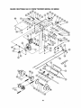
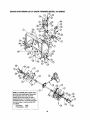
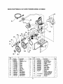
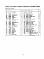
SEARS CRAFTSMAN
9.0 H.P. SNOW THROWER
28
MODEL 247.888550
SEARS CRAFTSMAN
Key
No.
Part No.
611-0053
9.0 H.P. SNOW THROWER
Description
Axle Assembly
Dogg Assembly:RH
Dogg Assembly:LH
2
3
618-0043
618-0044
4
7
9
618-0169
Shift Assembly: Track Dnve
683-0024
Hub Assembly: Track Drive
684-0014B Shift Rod Assembly
684-0021
FrictionWheel Support
Bracket Assembly
684-0031
Frame Assembly
r_4-0042B FrictionWheel Bearing
Assembly
710-0643
Hex Lock Screw 5/16-18 x
.625 Grade 5
10
12
14
17
Qty. Key
No.
2
2
4
18
19
20
710-0599
710-0602
710-0604
Hax Washer Hd. "17"Screw
Hex Washer Hd. TT Screw
Hex Washer Hd, TT Screw
2
8
6
21
22
710-0654A Hex Washer Hd. TT Screw
Hex Washer Screw
710-0788
4
1
23
24
710-0809
Hex Washer Screw
TT Screw
1
2
Hex Washer Head AB Screw
Oval C-Sunk Screw
Actuator Shaft
10
2
1
Hex Shaft: Track Ddve
1
25
27
28
710-0875
710-0898
710-1233
711-0911
29
i 30
711-1042
712-0127
33
36
712-0324
7!2-0711
37
38
39
713-0233
713-0413
713-0437
40
714-0474
Flanged Weld Nut #10-24
Top Lock Nut 1/4-20
Jam Nut 3/8-24
Chain Links
2
i1
1
1
Sprocket: 10T
Chain
1
2
Cotter Pin
1
MODEL 247.888550
Part No.
Description
Qty.
41
43
719-0295A Track Housing
725-0157
Cable Tie
46
47
732-0209
732-0264
48
49
736-0105
736-0160
Extension Spring
Extension Spring
Bell Washer
Flat Washer
50
51
52
54
738-0176
736-0242
736-0270
736-0287
Flat Washer
Bell Washer
Bell Washer
Flat Washer
2
5
2
2
58
59
738-0924
741-0339
Shoulder Screw
3
60
61
741-0563
741-1111
Flange Bearing
Ball Beadng
Hex Flange Bearing
4
2
2
62
63
64
746-0897
746-0898
746-0948
Auger Clutch Cable
Drive Clutch Cable
1
1
65
66
746-0950
748-0190
Track Steering Cable
Trigger Control
Spacer
2
2
1
67
70
71
748-0234
750-0903
750-0904
Shoulder Spacer
Split Spacer
SplitSpacer
2
2
1
74
75
76
750-0997
756-0625
784-5590
Spacer
Roller Cable
Shift Bracket
1
3
1
77
784-5609
80
81
82
784-5648
784-5687A
784-5688
Steering Cable Bracket
Frame Cover
1
1
Auger Clutch Cable Bracket
Drive Cable Bracket
1
1
83
784-5689A
Front Support Bracket
1
1
2
2
1
t
I1
NOTE: For painted parts, please refer to the list of color codes below. Please add the applicable color code,
wherever needed, to the part number to order a replacement part. For instance, if a part, numbered 700-xxxx, is
painted polo green, the part number to order would be 700-xxxx-0689.
Polo Green:
0689
Powder Black: 0637
29
f
SEARS CRAFTSMAN
9.0 H.P. SNOW THROWER
MODEL 247.888550
®
®
30
SEARS CRAFTSMAN
Key
No.
1
2
3
4
5
6
7
8
9
11
12
13
14
15
17
18
19
20
21
22
PartNo.
631-0032
684-0009
684-0024
684-0038
710-0157
710-0459
710-0604
710-1231
712-0214
712-0346
712-0429
720-0223
731-1292
731-1538A
736-0242
736-0272
736-0406
737-0170
738-0140
748-0353,_
9.0 H.P. SNOW THROWER MODEL 247.888550
Key
Qty. No.
Description
Wheel Assembly Idler
Rod Track Pivot
Axle Assembly
Handle Assembly
Screw
Screw
Screw
Screw
Lock Nut
Jam Nut
Hex Nut
Grip
Track
Wheel-Track Drive
Bell Washer
Flat Washer
Flat Washer
Lubricant
Shoulder Screw
Lift-Shaft Drive
2
1
1
1
1
1
2
2
1
4
6
1
2
2
1
4
4
1
4
1
23
24
25
26
27
28
29
30
31
32
33
34
35
36
37
38
39
40
Pad No.
750-0547
750-0909
750-0995
784-5639-048_
784-5642
717-1211
717-1209
717-1210
741-0542
718-0188
618-0046
711-0912
713-0414
715-0120
738-0502
736-0336
716-0115
716-0114
Description
Spacer
Spacer
Spacer
Plate-Track Side
Plate-Track Lockout
Gear Ring
Gear 12-Tooth
Gear 18-Tooth
Pin Dowel
Carrier
Carrier Assembly
Shaft--Track Drive
Sprocket--13 Tooth
Spring Pin
Flat Washer
Flat Washer
Snap Ring .625' Shaft
Snap Ring .56" Shaft
LABELS
Key
No.
1
2
3
4
5
6
7
8
Part
No.
777120077
777120078
777120079
777120401
777120402
777120404
777S30005
777S30004
Description
TractionControl RH
TractionControl LH
Chute Tilt
Auger Control
Traction Drive
Transport
Danger Warning
Danger, Top of Chute
Qty.
1
1
1
1
1
1
1
1
NOTE: For painted parts, please refer to the list of color codes below. Please add the applicable color code,
wherever needed, to the part number to order a replacement part. For instance, if a part, numbered 700-x.xxx,is
painted polo green, the part number to order would be 700-xxxx-0689.
PoloGreen:
0689
Powder Black: 0637
31
Qty.
2
2
2
2
1
2
6
2
6
2
2
1
1
1
6
2
2
1
SEARS CRAFTSMAN
9.0 H.P. SNOW THROWER
NOTE: For painted parts, please refer to
the list of color codes below. Please add
the applicable color code, wherever
needed, to the part number to order a
replacement part. For instance, if a part,
numbered 700-xxxx, is painted polo green,
the part number to order would be 700xxxx-068g.
Polo Green:
0689
Powder Black: 0637
32
MODEL 247.888550
SEARS CRAFTSMAN
Key
No.
Qty.
Key
No.
Bearing Housing
SpiralAssembly
1
1
20
21
732-0611
736-0119
ExtensionSpdng
LockWasher 5/16
1
9
SpiralAssembly
1
22
736-0169
LookWasher 3/8
1
Auger Gear Assembly
Spiral Housing Assembly
1
t
23
24
736-0174
736-0188
Wave Washer
1
Impeller Assembly
Chute Reinforcement
1
1
25
26
736-0242
736-0463
FlatWasher .76 I.D. x 1,49O.D.
Bell Washer .345 I.D. x .88
6
16
Carriage Screw I/4-20 X ,75
Carriage Bolt 5/16-18 X .75
Hex Scr 3/8-24 X 1,5
5
10
1
27
28
29
738-0281
741-0245
741-0309
Flat Washer 1/4 x .630
Shoulder Screw
5
f
Hex Flange Beadeg
2
Ball Bearing
1
6
741-0475
741-0493A
756-0178
Pad No.
1
05931
2
3
605-5192A
605-5193A
4
618-0121
5
6
684-0040A
684-0065
7
8
705-5226
710-0703
9
710-0451
10
710-0459A
It
710-0604
9.0 H.R SNOW THROWER MODEL 247.888550
Description
Part No.
Description
Qty.
12
710-0890A
Hex Washer Head 1-r-Screw
5/16-18 X .62
Shear Bolt5/16-18 X 1.5
2
30
31
32
13
712-0116
Jam Lock Nut
1
33
784-5582A
Flange Bushing
Flat Idler
Shave Plate
14
15
712-0324
712-0429
Toptock Nut 1/4-20
5
34
784-5580
Slide Shoe
2
2
1
35
36
784-5618
784-5632A
2
712-0798
Hex Lock Nut 5116-18
Hex Nut 3/8-16
Bearing Assembl,/
16
17
712-3010
Hex Nut 5/16-18
19
37
784-5647
Auger Idler Arm
Chute Crank Bracket
1
1
18
715-0114
Spiral Pin
2
38
712-3068
Patch Nut 5/16-18
1
737-3007
710-0260
Grease
1
Carriage Bolt 5/16-18 x .62"
4
19
731-1379A
Chute Adapter
1
39
40
: Plastic Bushing
1
4
1
1
I
I
Key
NO
1
2
3
4
5
6
7
8
9
Part No.
618-0123
618-0124
710-0642
711-0909
714-0161
715-0143
717-0526
717-0528
718-0186
Descdpfion
aty
Housing---RH
Housing--LH
Screw
Spiral Axle
Key, Hi-Pro
Spiral Pin
Shaft Worm
I Worm Gear
Thrust Collar
1
1
5
1
1
1
1
1
1
Key
No.
10
11
12
13
14
15
16
17
18
33
Part No,
721-0325
721-0327
721-0328
736-0351
736-0369
736-0445
737-0168
741-0662
741-0663
i
I
Descdption
Plug
Seal, Oil
Lo_ite 5699, Ultra
Washer
Washer
Washer
Grease
Flange Bearing
Flange Beadng
c_y
2
4
1
1
1
1
SEARS CRAFTSMAN
Key
No.
1
2
3
4
5
6
7
9
10
11
12
13
14
15
16
17
Pad No.
05896A
629-0071
710-0627
710-1245
710-0230
710-3005
710-0696
710-1652
712-0181
731-1324
732-0710
736-0119
736-0242
736-0247
736-0270
736-0331
9.0 H.P. SNOW THROWER
Description
Bracket
Extension Cord
Screw
Screw
Screw
Screw
Screw
Screw
Jam Nut
Belt Cover
Spring
Flat Washer
Bell Washer
Flat Washer
Lock Washer
Bell Washer
MODEL 247.888550
Key
No.
18
19
20
21
22
23
24
25
26
27
28
29
Qty.
1
1
2
1
1
1
1
2
1
1
1
1
1
1
1
1
34
Pad No.
736-0505
748-0234
748-0360
754-0346
754-0430
756-0313
756-0569
756-0967
756-0986
756-0987
390-987
30
770-10051C
31
737-3007
Description
Flat Washer
Shoulder Spacer
Adapter Pulley
V-Belt
V-Belt Matched
Flat Idler
Half Pulley
Auger Pulley
Pulley Half
Pulley Half
Starter
Engine, Craftsman
model143,999005
Owner's Manual
(Not Shown)
Grease
Qt_,
1
1
1
1
2
1
4
2
1
1
1
Craftsman
Engine Model No. 143.999005
for Craftsman Snow Thrower Model 247.888550
CARBURETOR
Key
No.
0
I
20A
_P_37
"25
35
Part
No.
640052
1
2
6
7
10
14
15
16
17
631776A
631970
631778
650506
632112
632174
630735
632164
650417
18
20
20A
25
630766
640016
640053
631951
27
28
29
30
631024
632019
631028
631021
31
32
33
36
37
40
44
47
631022
27136A
27554
640005
632547
640055
27110
630748
48
631027
Description
Carburetor (Incl. 184 of
Engine Parts List)
Throttle Shaft & Lever Ass'y
Throttle Return Spring
Throttle Shutter
Shutter Screw
Choke Shaft & Lever Ass'y.
Choke Shutter
Choke Positioning Spring
Fuel Fitting
Throttle Crack Screw/Idle
Speed Screw
Tension Spring
Idle Restrictor Screw
Idle RestrictorScrew Cap
Float Bowl Ass'y. (Incl. 32 &
33)
Float Shaft
Float
Float Bowl "O" Ring
Inlet Needle, Seat & Clip
(Incl. 31)
Spring Clip
Bowl Drain Ass'y.
Drain Plunger Gasket
Main Nozzle Tube
O Ring
High Speed Bowl Nut
Bowl Nut Washer
Welch Plug, Idle
Mixture Well
Welch Plug, Atmospheric
Vent
Qty.
1
1
1
1
2
1
1
1
1
I
I
I
1
1
1
1
1
1
1
1
1
2
1
1
Craftsman
Engine Model No. 143.999005
for Craftsman
Snow Thrower Model 247.888550
>300
18
305
!_120
,308
87
70
69
101
224.
'q_325
323
282
173
182
185.
25
"275
26
315
9O
370C
200 x
f
f
327
36
Craftsman
Engine Model No. 143.999005
Key
No.
Part
No.
1
2
3
4
5
15
15A
15B
16
17
18
19
20
25
26
28
30
35
36
37
38
40
40
41
41
42
42
43
45
47
48
49
50
60
65
69
70
71
75
76
80
81
82
83
84
86
87
89
35385
27652
650820
Description
for Craftsman
Qty.
Key
No.
Cylinder
1
Dowel Pin
2
Screw
2
Oil Drain Extension
1
30969
Extension Cap
1
1
30699C Governor Rod
30700
Governor Yoke
1
Screw
1
650494
33454
Governor Lever
1
29916
Governor Lever Clamp
1
651028
Screw, Torx
1
34663
Speed Control Spring
1
35319
Oil Seal
1
36460
Blower Housing Baffle
1
Screw
2
650561
30322
Lock Nut
1
35980A Crankshaft
1
Screw
1
29826
29918
Lock Washer
1
Lock Nut
1
29216
29642
Retaining Ring
1
40011
Piston, Pin & Ring Set (Std.)
1
40012
Piston, Pin & Ring Set (.010" O ;) 1
40009
Piston, & Pin Ass'y.(Std.)
1
40010
Piston, & Pin Ass'y.(.010" OS)
1
40013
Ring Set (Std.)
1
40014
Ring Set (.010" OS)
1
27888
Piston Pin Retaining Ring
2
36897
Connecting Rod Ass'y.
1
651033
Connecting Rod Bolt
2
34034
Valve Lifter
2
36896
Oil Dipper
1
36655
Camshaft (MCR)
1
33273A Blower Housing Extension
1
650128
Screw
1
35262A Cylinder Cover Gasket
1
35445A Cylinder Cover
1
35377
Crankshaft Bushing
1
Oil seal
1
35319
28926
Camshaft Seal
1
31845
Governor Shaft
1
30590A
Washer
1
35378
Governor Gear Asss'y.
1
30588A Governor Spool
1
29193
Retaining Ring
1
Screw
7
650833
650832_ Screw
1
32589
Flywheel Key
1
Snow Thrower Model 247.888550
Part
No.
90
92
93
100
101
102
103
110
110A
119
120
125
125
126
126
127
130
130A
130B
135
139
140
149
149A
150
151
169
170
171
172
173
174
178
182
183
184
611093
650880
650881
35135
610118
651024
651007
35187
37047
36448
36449
27878A
27880A
34035
34036
650691
6021A
650727
650727
35395
33369
650836
27882
35862
27881
32581
27896A
28423
28424
28425
35350
6501281
29752
30088A
34587A
33263
185
186
186B
200
203
204
206
207
209
215
219
33877
34667
36652
34677
31342
651029
610973
33878
650821
35440
34586
Description
Qty.
Flywheel (W/Ring Gear)
BellevilleWasher
Flywheel Nut
Solid State Ignition
Spark Plug Cover
Solid State Mounting Stud
Screw, Torx
Ground Wire
Ground Wire
Cylinder Head Gasket
Cylinder Head
Exhaust Valve (Std.)
Exhaust Valve (1/32" Os)
Intake Valve(Std.)
Intake Valve (1/32" Os)
Washer
Screw
Screw
Screw
Resistor Spark Plug
Governor Gear Bracket
Screw
Valve Spring Cap
Valve Spring Cap
Valve Spring
Valve Spring Keeper
Valve Cover Gasket
Breather Body
Breather Element
Valve Cover
Breather Tube
Screw
Nut & Lock Washer
Screw
Choke Bracket
Carburetor to intake
pipe gasket
Intake Pipe
Governor Link
Choke Spring
Control Bracket
Compression Spring
Torx. Screw
Terminal
Throttle Link
Screw
Control Knob
Choke Rod
1
1
1
1
1
2
2
1
1
1
1
1
1
1
1
2
7
2
2
1
1
2
1
1
2
2
1
1
1
1
1
2
2
2
1
1
1
1
1
1
1
1
1
1
2
1
1
Table continued on next page
37
Craftsman
Engine Model No. 143.999005
for Craftsman
Snow Thrower Model 247.888550
Table continued from previous page
Key
No.
Part
No.
Description
220
222
223
224
260
261
262
264A
265
275
276
277
281
282
285
287
290
292
298
3OO
301
305
307
308
310
314
315
35438
28820
650378
27915A_
35447A
650788
29747B
650802
33272B
35056
31588
651002
33013
650760
35985B
29752
30705
26460
650665
34156A
35355
35554
35499
35540
36205
650873
611111
Choke Knob
Screw
Screw, Torx
Intake Pipe Gasket
Blower Housing
Screw
Screw, Torx
Screw
Cylinder Head Cover
Muffler
LockingPlate
Screw
Starter BubbleCover
Screw
Starter Cup
Nut & Lock Washer
Fuel Line
Fuel Line Clamp
Screw
Fuel Tank
Fuel Cap
Oil Fill Tube
=O" Ring
Fill Tube Clip
Dipstick
Screw
Alternator Coil
Qty.
1
2
2
1
1
2
2
1
1
1
1
2
1
1
1
4
1
4
2
1
1
1
1
1
1
1
1
38
Key
No.
Part
No.
323B
325
327
328
329
335
336
338
340
341
342
343
350
351
355
364
365
370C
370H
3701
360
390
396
400
900
900
611118
29443
35392
35593
610973
35057A
650765
28942
34154
34155
650561
35079
570682
32180C
590574
33377
650767
36501
35077
35878
640052
590749
37000
36450A
Description
Terminal
Wire Clip
Starter Plug
Ignition Key
Terminal
Carburetor Cover
Screw
Screw
Fuel Tank Bracket
Fuel Tank Bracket
Screw
Key Switch Bracket
Primer Bulb
Primer Line
Starter Handle
Carburetor Cover Bracket
Screw
Primer Decal
Choke Decal
Warning Decal
Carburetor
Rewind Starter
ElectricStarter Motor
Gasket Set
Replacement Engine--none
Replacement Short Block
756325
Order from 71-999
Qty,
1
1
1
2
1
1
1
2
1
1
1
1
1
1
1
1
2
1
1
1
1
1
1
1
0
Craftsman
Engine Model No. '143.999005 for Craftsman
Snow Thrower Model 247.888550
Recoil Starter
mll
Key
No.
12
13
Pa_
No.
0
1
2
3
4
5
6
7
8
11
12
590733
590599A
590600
590696
590601
590697
590698
590699
590709
590734
590535
13
590574
_mS
Description
Rewind Starter
Spring Pin (Incl. 4)
Washer
Retainer
Washer
Brake Spring
Starter Dog
Dog Spring
Pulley & Rewind SpringAss'y
Starter Housing Ass'y.
Starter Rope (Length 98" x
9/64" Dia.)
Mitten Grip Handle (Not
Included With Starter)
a_.
1
1
1
1
1
1
2
2
1
1
Recoil Starter (Optional)
--11
Key , Part
No.
No.
12
°,#-,
0 590749
1 590599A
2 590600
3 590679
4 590601
5 590678
6 590680
7 590412
8 590682
11 590750
12 _ 590535
13
B--5
39
590574
Description
Rewind Starter
Spring Pin (Incl. 4)
Washer
Retainer
Washer
Brake Spring
Starter Dog
Dog Spring
Pulley & Rewind Spring Ass'y.
Starter Housing Ass'y.
Starter Rope (Length 98" x
9/64" Dia,)
Mitten Grip Handle (Not
Included With Starter)
Qty.
1
1
1
1
1
1
2
2
1
1
1
1
Date
Comments
62
In U.S.A. or Canada
for in-home
major brand repair service:
Call 24 hours a day, 7 days a week
1-800-4-MY-HOME
Para pedir servicio
de reparaci6n
sM(1-800-469-4663)
a domiciliio
m 1-800-676-5811
Au Canada pour tout le service ou les pi_ces --
For the repair or replacement
Call 6 a.m. -- 11 p.m. CST,
1-800-469-4663
parts you need:
7 days a week
PartsDirect sM
1-800-366-PART
(1-800-366-7278)
Para ordenar piezas con entrega a domicillio m 1-800-659-7084
For the location of a Sears Service Center in your area:
Call 24 hours a day, 7 days a week
1-800-488-1222
To purchase or inquire about a Sears Maintenance Agreement:
Call 7 a.m. -- 5 p.m. CST, Monday -- Saturday
1-800-827-6855
p,-
SEARS
HomeCentral""