1
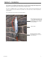
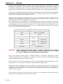
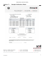
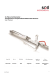
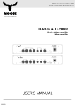
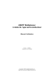
Mems Tiltmeter (IPI Sensor Based) User Manual Man193 2.0.2 07/08/2014 Final Chris Rasmussen Phil Day Manual No. Revision Date Originator Checked Authorised for Issue User Manual 1 Contents Section 1 : Introduction ................................................................................................................3 Section 2 : Installation .................................................................................................................4 2.01 2.02 2.03 Identify Components and Tools Needed ................................................................................... 4 Drill Anchor Hole ............................................................................................................................ 4 Attach Tiltmeter ............................................................................................................................. 4 Section 3 : Wiring ...........................................................................................................................5 Section 4 : Taking Readings/Logger Programming ...........................................................6 Section 5 : Data Reduction ..........................................................................................................9 Section 6 : Sample Installation Record Sheet .................................................................... 10 Section 7 : Sample Calibration Sheet .................................................................................... 11 User Manual 2 Section 1 : Introduction The Soil Instruments Mems Tiltmeter is based on the Soil Instruments In Place Inclinometer (IPI) sensor. It is designed for attaching to structures where a larger tilt range (in arc degrees) is required than can be achieved with EL based sensors. The use of a MEMS sensor in the Tiltmeter gives a large range with high sensitivity and relative immunity from the effects of long cable runs. The sensor has on-board temperature compensation. The components of the system are identified below. Label identifying sensitive axis – in the case pictured the wall is expected to move outwards so the sensitive axis is at 90° to the wall itself Sensor Body Mounting bracket to attach the Tiltmeter to the structure to be monitored User Manual 3 Section 2 : Installation The following tools are required for installation; 3mm & 5mm Allen keys A drill and bit suitable for drilling an M8 anchor hole Adjustable spanner Small flat blade screwdriver (for wiring) A selection on M8 nuts and washers The installation procedure is detailed below:- 2.01 Identify Components and Tools Needed Sensor body and bracket M8 anchor and accessories (nuts, washers, lock-nuts) Drill and bit Hand tools as above Mark out the position on the structure to be monitored where you wish to place the tiltmeter, ensuring that once the installation is completed the sensitive axis of the tiltmeter will be in the direction of expected movement. (This can easily be accomplished by holding the tiltmeter up to the structure and checking the orientation of the top label) 2.02 Drill Anchor Hole Once the location for the tiltmeter has been agreed and the hole marked out, drill the hole to accept the supplied M8 anchor. Ensure that appropriate PPE (Personal Protective Equipment) is worn (e.g. gloves, eye protection and if needed ear protection) during this operation. Drill the hole to a deep enough so when the anchor is inserted the shell can expand to grip the structure, but not too deep so insufficient thread is left to attach the tiltmeter. Take great care to ensure that the hole is drilled straight into the structure and not at an angle to it. Once the hole is drilled, insert the anchor and fully tighten the M8 nut to secure it to the structure. 2.03 Attach Tiltmeter If the structure is smooth walled (such as the one in the photographs above), then the nut used to tighten the anchor should be sufficient to stand the tiltmeter bracket away from the structure so that the tiltmeter body does not touch it. If this is the case, then fit a washer between nut and the tiltmeter and proceed as below. If this is not the case and additional clearance is required, fit a second M8 nut and then a washer as needed to space the tiltmeter away from the structure. Once the correct spacing has been set, slide the tiltmeter bracket assembly onto the stud and secure using a second washer and then a M8 lock-nut. Use a spirit level to ensure that the tiltmeter body is level in both directions and then tighten the lock-nut to secure. The installation is now complete. If the tiltmeter is to be in direct sunlight, and/or is in a position where it may be knocked or tampered with, it is good practice to fabricate and fit a cover (which in the case of sunlight protection should be painted white). Ensure that any such cover does not come into contact with the tiltmeter and therefore interfere with its operation. User Manual 4 Section 3 : Wiring The Soil Instruments tiltmeter sensor can be read by most commercially available dataloggers. Soil Instruments recommend the Campbell datalogger range and can supply a fully built up datalogger with enclosure, logging program and a variety of communications options from a simple direct link to satellite modem, please see our datalogger datasheets. We do not recommend that tiltmeter sensors are read with a manual readout as this defeats the object of in-place sensors, however if desired, a voltmeter can be used. (An external 1216VDC power supply will be needed to do this). Whatever the datalogger or reading method, the wiring remains the same. The sensors are supplied with a polyurethane-jacketed 4-core cable (6 for bi-axial sensors) suitable for long term immersion in water at depths of up to 200m. The cable has four or six conductors, a foil, braid and drain wire. The drain wire and screen are not connected at the sensor end of the cable and thus should be connected to ground at the datalogger end for maximum resistance to induced voltages and interference. The sensor is a differential device and thus a + and – reading must be taken. The conductor colour codes are as per the table below:Conductor Colour Identification Red Power+ (10-16VDC) Black Ground White Green Signal Low Blue B axis Signal High Yellow (bi-axial sensor) Signal Low Bare Wire WARNING: Signal High A axis Drain (Screen) Take extreme care whilst wiring to ensure conductors are correctly wired, especially the red power conductor and all of the output conductors. Always wire with the power switched off. When using Bi-axial sensors with a Campbell AM416 or AM16/32 multiplexers, please contact Soil Instruments if assistance is needed in wiring to meet the CR10/CR1000 logger protocols detailed in Section 4 of this manual. If it is desired to check the functioning of the sensors immediately after installation, at zero degrees tilt (i.e. true vertical), the sensor output is approximately 0VDC. When wiring into a datalogger it is good practice to wire the first sensor (or lowest serial number) to the first channel, the second sensor to the second channel etc. If a program not supplied by Soil Instruments is being used the following protocol should be observed to obtain the best results. Power sensors on, wait for 3 seconds, take a minimum of 50 readings (differential voltage) at minimum 100 millisecond intervals and average. User Manual 5 Section 4 : Taking Readings/Logger Programming The Soil Instruments tiltmeter sensors are designed to be read by Campbell datalogger systems. Other dataloggers can be used, including the Campbell CR1000 loggers, but the basic reading and excitation architecture outlined in this section must be followed. Sensors should be read via a multiplexer (Campbell AM416 or AM16/32) and the following sequence must be used to ensure best sensor performance: Activate multiplexer Switch to first channel a) Switch on power supply to sensor (on Campbell loggers use the Switched 12Volt option) b) Let the sensor warm up for at least 3 seconds c) Take a minimum of 50 differential measurements and store the average d) Switch power to the sensor off e) Switch to the next channel Repeat step a) through e) for the next sensor De-activate multiplexer Note: a sample program for a CSI CR10X unit is printed below – for CR800 and CR1000 programs, please contact Soil Instruments. Sensors can be left powered when not being read, but for maximum life we do not recommend this. When using multiplexer units this is not possible and the above sequence should be observed. When long cables are used make sure to increase the settling time for the datalogger measurements to achieve optimal performance. These sample CR10X instructions below assume:C1 = Act-multiplexer 1 C7 = Act Switched 12Volt C8 = CLK pulse for multiplexer Measuring channel is differential channel 1 Multiplexer = CSI AM16/32 (in 4x16 mode) ; Set C8 for CLK pulse ; Activate multiplexer 1 on C1 1: Set Port(s) (P20) 1: 4000 C8..C5 = 10ms/low/low/low 2: 0001 C4..C1 = low/low/low/high ;Start a loop for 16 IPI sensors Uni-axial or 8 IPI sensors Bi-Axial 2: Beginning of Loop (P87) 1: 0000 Delay 2: 16 Loop Count ; Send a CLK pulse 3: Do (P86) User Manual 6 1: 78 Pulse Port 8 ; Activate SW12Volt 4: Do (P86) 1: 47 Set Port 7 High ; Let the sensors warm up for at least 3 seconds 5: Excitation with Delay (P22) 1: 3 Ex Channel 2: 0000 Delay W/Ex (0.01 sec units) 3: 300 Delay After Ex (0.01 sec units) 4: 0 mV Excitation ; Start a loop for 50 measurements 6: Beginning of Loop (P87) 1: 0000 Delay 2: 50 Loop Count ; Measure the sensors differential on channel 1 7: Volt (Diff) (P2) 1: 1 Reps 2: 5 2500 mV Slow Range 3: 1 DIFF Channel 4: 2 -- Loc [ measmV_01 ] 5: 1.0 Multiplier 6: 0.0 Offset 8: End (P95) ; De-Activate the SW12Volt 9: Do (P86) 1: 57 Set Port 7 Low ; Take the Average of the measurements and store it 10: Spatial Average (P51) 1: 50 Swath 2: 2 First Loc [ measmV_01 ] 3: 1 -- Avg Loc [ IPImV_01 ] ;End of Loop 11: End (P95) ;De-Activate multiplexer 1 12: Do (P86) 1: 51 Set Port 1 Low ;Do other processing here …………… ;Then store the data User Manual 7 If in any doubt we recommend contacting Soil Instruments for advice. The performance of the sensors as calibrated is not guaranteed unless the above protocols are used. Soil Instruments can supply full logger programs and wiring diagrams at an extra cost, please contact us for details. User Manual 8 Section 5 : Data Reduction The Soil Instruments tiltmeter sensor is calibrated over ±5 or ±10 arc degrees (approx. ±87 or ±175mm/metre) and has a DC voltage output dependant on tilt. The sensors are calibrated for tilt only (please see note on temperature below) and the unit of calibration (either Arc Degrees or mm/metre) is specified at the time of order. The calibration certificate supplied with the sensor (please see section 6) contains the following information: Instrument Type Serial Number Range Calibration Data (both raw and reduced) Conversion Formula FS Error % at each calibration point Wiring Code Note: As the tiltmeter is based on an IPI sensor, the calibration takes place in the IPI calibration jigs, therefore the calibration certificate will evidence an IPI sensor, this is quite normal and all of the factors are correct. A positive resultant indicates movement towards the A+ (+mm) direction; a negative resultant indicates movement towards the A- (-mm) direction. The calibration factors can easily be loaded into a spreadsheet and data added via cut and past or an automated program such as I-Site can be used, in which case the application of calibration factors and gauge length is fully automatic. The MEMS Accelerometer chip used in the tiltmeter sensor is calibrated for temperature as part of the micro-machine manufacturing process by the chip manufacturer. As well as the MEMS tilt element the sensor contains a microprocessor and a look up table to apply correction for temperature changes to the silicon substrate within the sensing element. Soil Instruments has no control over this process other than by the QA procedures followed by the chip manufacturer, which specify the correction and rejection criteria. The sensor output is therefore corrected automatically for the effects of temperature on the accelerometer chip. Please note that this correction will not apply to unknown factors within the sensor string or borehole where an external change may well be occurring. Soil Instruments do not offer the sensor with an on-board temperature sensor. If temperature measurement is desired, then a separate temperature sensor must be installed additional to the tiltmeter sensor. User Manual 9 Section 6 : Sample Installation Record Sheet MEMS Tiltmeter Installation Sheet Location User Manual Date Installer Site Sensor Number Serial Number A+ Direction Notes 10 MEMS Tiltmeter (IPI Sensor Based) Section 7 : Sample Calibration Sheet Bell Lane, Uckfield, East Sussex t: +44 (0) 1825 765044 e: [email protected] TN22 1QL United Kingdom f: +44 (0) 1825 744398 w: www.itmsoil.com Soil Instruments Ltd. Registered in England. Number: 07960087. Registered Office: 5th Floor, 24 Old Bond Street, London, W1S 4AW User Manual 11