1
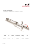
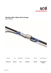
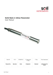
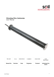
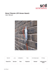
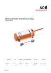
Beam Electrolevel, Electrolevel Tiltmeter & Helm User Manual Man173 7.0.3 08/08/2014 C. Rasmussen Phil Day Phil Day Manual No. Revision Date Originator Checked Authorised for Issue User Manual 1 Contents Section 1 : Introduction ................................................................................................................................. 3 Section 2 : Installation ................................................................................................................................... 5 2.01 2.02 2.03 Horizontal Beam & Sensor Installation ..................................................................................... 5 Tiltmeter and Vertical Beam & Sensor Installation ................................................................ 6 Zeroing the Sensor Using the HELM Readout ......................................................................... 9 Section 3 : Zeroing a Sensor ......................................................................................................................10 Section 4 : Wiring ...........................................................................................................................................11 Section 5 : Data Reduction .........................................................................................................................13 5.01 5.02 Section 6 : Appendix A. User Manual (A) For Linear (5mm) Calibrations ........................................................................................13 (B) For Polynomial (13 and 5 mm) Calibrations ..............................................................14 Calibration ..................................................................................................................................15 Sample Installation Record Sheet ..................................................................................16 2 Section 1 : Introduction This manual covers four Soil Instruments related products; Beam Electrolevel Electrolevel Tiltmeter HELM readout Radio enabled Electrolevel zeroing The Beam Electrolevel is used to monitor vertical deflections (heave or settlement) and is mounted horizontally in beams typically 1 to 2.5 metres in length. The Electrolevel Tiltmeter is designed to be either attached to a structure or a vertical beam and the HELM is a set up and readout tool for both Electrolevel products. Horizontal Electrolevel Beam containing the Electrolevel sensor Electrolevel Tiltmeter; for attachment directly to a structure or vertical beam User Manual 3 The HELM (Hand Held Electrolevel Meter); reads all Soil Instruments Electrolevel products, as well as up to 20VDC and 2K, making it an ideal readout for a variety of instruments as well as a tool to check power supplies and lead / sensor continuity User Manual 4 Section 2 : Installation The installation section of this manual is split into three parts; Horizontal beam and sensor installation Tiltmeter direct and Vertical beam installation Sensor zero setting (common to both sensor types) The wiring is also common and dealt with in the wiring chapter. 2.01 Horizontal Beam & Sensor Installation The nominal beam length will have been specified at time of order; a parts list for a single beam installation is detailed as follows; Horizontal Beam with end fittings Horizontal Beam sensor (may be already fitted into beam) Two anchor end kits These parts are pictured below. The installation sequence is as follows; 1. 2. 3. drill mounting holes and fit anchors attach and level beam zero sensor The anchor kit supplied by Soil Instruments has either an expanding shell M10 anchor or a groutable M10 anchor and a 12mm drill bit. Both require a 12mm hole to be drilled approximately 60mm deep into the structure to be monitored. Hold the beam up against the structure with a spirit level along the top face, level and mark the centre of each end fitting, remove the beam and drill two holes to approximately 60mm depth. If using an expanding shell anchor, insert and set with the supplied tool. If using a groutable anchor, grout and wait the required time for setting (with quick set adhesive such as Hilti HIT-HY 150 this is approximately thirty minutes at 20°C) Before installing the beam, fit the sensor into the beam (if not already there) and check that the two retaining screws through the back of the beam to the sensor are tight. The anchor kit has a series of nuts and washers, to ensure that longitudinal thermal expansion of the beam does not cause spurious readings; these must be fitted in the correct order, detailed below, from the wall outwards. User Manual 5 1. 2. 3. 4. 5. 6. 7. 8. 9. Steel washer 1st Nyloc nut 2nd Nyloc nu, Steel washer Plastic washer Beam end fitting Plastic washer Steel washer Nylock nut The nylock nut should be tightened so that the Beams, including the end Beam, do not rattle around, but you should be able to move them back and forth with a small amount of force. A drawing of the correct sequence is below for both a single and a pair of beams (where a pair will share end fittings). Right; single beam end fitting Far right; a pair of beams sharing a single mounting stud (note extra washer between beams) Once the anchors are in place and the beam fitted, check with a spirit level that both horizontal axis of the beam are level (i.e. both along and across the beam), it may be necessary to loosen the large bolt which attaches the end fitting to the beam by approximately one turn and rotate the beam to achieve the across level. Once level, carefully re-tighten the end fitting bolts. Repeat the above for further beams, sharing end fittings as shown above to achieve a continuous string of sensors. Before zeroing the sensors, it is desirable to run the cables to the Datalogger or readout point, but not to make the connection to the sensor. It is permissible to attach cables to beams, but slack cable must be left (by forming an ample omega loop) at the joint between a pair of beams to allow for movement. Once all of the above is complete the beam can be set to zero, (please refer to section 3: Zeroing a Sensor in this manual for more details) and then wired, (please refer to section 4: Wiring in this manual for more details) 2.02 Tiltmeter and Vertical Beam & Sensor Installation The Tiltmeter has two uses; it can be fitted directly to the structure for vertical settlement / heave monitoring, or onto a vertical beam for lateral deflections. To fix directly to a structure, hold the Tiltmeter against the structure, with a spirit level on top and mark the location of the two fixing holes. The Tiltmeter can be fixed using expanding plastic anchors such as Raw Bolts, expanding shell anchors, or groutable anchors. Ensure that the anchor head bolt (whichever method is used) has a washer between it and the Tiltmeter mounting plate. User Manual 6 Right; a typical installation is shown right of a Tiltmeter and L-Bracket attached to a concrete structure The Tiltmeter can also be attached to a vertical beam, the nominal beam length will have been specified at time of order; a parts list for a single beam installation is detailed as follows: Vertical beam with end fittings Vertical Tiltmeter with fitting kit (may be already fitted onto beam) Two anchor end kits (must be vertical anchor kits) Left; biaxial Tiltmeters attached to a vertical beam The installation sequence is; drill mounting holes and fit anchors attach and level beam zero sensor The anchor kit supplied by Soil Instruments has either an expanding shell M10 anchor or a groutable M10 anchor and a 12mm drill bit. Both require a 12mm hole to be drilled approximately 60mm deep into the structure to be monitored. Hold the beam up against the structure with a spirit level along the side face, level and mark the centre of each end fitting, remove the beam and drill two holes to approximately 60mm depth. If using an expanding shell anchor, insert and set with the supplied tool. If using a groutable anchor, grout and wait the required time for setting (with quick set adhesive such as Hilti HIT-HY 150 this is approximately thirty minutes at 20°C) Before installing the beam, fit the sensor into the beam (if not already there) and check that the two retaining screws on the rear of the Tiltmeter mounting bracket are tight. The Tiltmeter should be set at a 90° angle to the structure to be monitored. The anchor kit has a series of nuts and washers, to ensure that longitudinal thermal expansion of the beam does not cause spurious readings; these must be fitted in the correct order, detailed below, from the wall outwards. User Manual 7 Single Beam End Fitting 1. 2. 3. 4. 5. 6. 7. Back nut Steel washer Plastic washer Plastic washer Plastic washer Steel washer Nylock nut Pair of Beams Sharing a Single Mounting Stud 1. 2. 3. 4. 5. 6. 7. 8. 9. 10. Back nut Steel washer Steel washer Standard Nut Steel washer Plastic washer Plastic washer Plastic washer Steel washer Nylock nut Once the anchors are in place and the beam fitted, check that the Tiltmeter is at 90° to the structure to be monitored. It may be necessary to loosen the large bolt which attaches the end fitting to the beam by approximately one turn and rotate the beam to achieve the correct level. Once level, carefully retighten the end fitting bolts. Repeat the above for further beams sharing end fittings, as shown above, to achieve a continuous string of sensors. Before zeroing the sensors, it is desirable to run the cables to the Datalogger or readout point, but not to make the connection to the sensor. It is permissible to attach cables to the beams, but slack cable must be left (by forming an ample omega loop) at the joint between a pair of beams to allow for movement. Once all of the above is complete the beam can be set to zero, (please refer to section 3: Zeroing a Sensor in this manual for more details) and then wired, (please refer to section 4: Wiring in this manual for more details) User Manual 8 2.03 Zeroing the Sensor Using the HELM Readout The Electrolevel sensor used in the beam sensor and the Tiltmeter is a narrow angle, high accuracy device. As such, it must be set to zero when installed to allow both the maximum range for the monitoring to take place and to maximise the insensitivity to temperature variations. This task is simply achieved using the Soil Instruments HELM readout. The HELM has two switches, which select the following; Left Hand Switch Right Hand Switch Off/On Backlight Off Electrolevel Backlight On Volts (0-20VDC) Sounder On Ohms (0-2k Backlight and Sounder On A full explanation of each function is below. Left Hand Switch Off/On Switches HELM off or on regardless of the position of the right hand Switch Electrolevel (symbol) Places the HELM into Electrolevel read mode, right hand switch allows selection of backlight and sounder Volts (symbol) Selects voltmeter mode, the HELM can read 0-20VDC with an accuracy of 20%FS Ohms (symbol) Selects Ohms mode, the HELM can read 0-2k with an accuracy of 2%FS Right Hand Switch Off Backlight and sounder are off Backlight (symbol) Switches on display backlight for use in tunnels and at night Sounder (symbol) Turns on an audible tone which increases in volume as zero is approached on an Electrolevel sensor. This allows for the sensor zero to be set without the need to view the display. Backlight & Sounder (Symbol) Turns both the backlight and the sounder on. Note, battery life will be shortened if the HELM is continuously run in this mode User Manual 9 Section 3 : Zeroing a Sensor To zero a sensor, proceed as follows. Connect the lead supplied with the HELM to the small silver jack socket on the PCB adjacent to the sensor housing. Switch the HELM on and select ‘Electrolevel mode’ with the desired combination of sounder and backlight. Use the two adjuster screws, in unison to bring the reading on the display as close to zero as possible. It is desirable to set the sensor to within 10 digits of zero, which equates to approximately 20 arc seconds (0.097mm/metre) from absolute sensor zero. Take care not to over tighten the two adjuster screws. When the zero has been set, withdraw the HELM lead from the sensor jack socket and apply a small amount of acrylic varnish to lock the screws against vibration. User Manual 10 Section 4 : Wiring Soil Instruments Electrolevel products require precise AC excitation and must be read with the same type of readout with which they were calibrated. The factory calibration is carried out with Campbell ‘CR Table Based’ products that apply AC excitation, the data from this being used to derive the HELM calibration factors. Therefore, Soil Instruments only recommends and supports our Electrolevel products when read with a ‘CR Table Based’ product or a HELM. The sensors can be read by simply plugging the HELM into the connector on the sensor PCB, in which case no external wiring is required. Alternatively, cables can be run to a central switch box from where HELM readings can be taken. The wiring for the external switch box/HELM option is contained in the manual supplied with the switch box, this manual concerns wiring to a ‘CR Table Based’ system only. If the ‘CR Table Based’ product has been supplied by Soil Instruments, it will have a wiring diagram included within it. If others are supplying the ‘CR Table Based’ and writing the read/log program, then the table below contains the information they need to connect sensors to either/or a /AM416/AM16/32 and the ‘P’ program instruction ranges. If in doubt we highly recommend that Soil Instruments are contacted for advice and a logging program. Connector Strip On PCB Function Pin 1 Excitation; any Vx channel Pin 3 Output; any SE channel Pin 4 Ground; BR Half Instruction Parameter Range mV2500 Excitation 2500 Reverse Excitation True Settling Time User Manual closest to Vx channel 0 Integration Time 250 NSec Multiplier 10 11 WARNING the PCB on the Tiltmeter is orientated the opposite way to an Electrolevel PCB Wiring Connections for an Electrolevel PCB Orientation for an Electrolevel PCB Wiring Connections for a Tiltmeter PCB Orientation for a Tiltmeter It is mandatory to use a cable which conforms to Belden 9927 specifications, Soil Instruments 4C cable is ideal. No guarantee of performance can be made or given unless this requirement is adhered to. The comments below in respect of temperature effects on cable and long cable runs apply only to Belden 9927 specification cable. Soil Instruments has extensive data on the effects of cable lengths with Electrolevel sensors. The sensor used has a relatively high resistance/impedance in comparison with the cable, thus cable runs between sensor and Datalogger/readout box of up to 250 metres may be used. The same resistance/impedance relationship exits for change in cable properties due to temperature; a temperature range (over a year) of up to 70C is tolerated without the need for additional precautions. User Manual 12 Section 5 : Data Reduction Two calibrations are available. These are based on two tilt ranges, a narrow angle range resulting in a linear (slope and offset) calibration and a wider angle range resulting in a 5 th order polynomial calibration. Depending on the expected range of movement and the accuracy required, the user selects which calibration to use. The table below contains details of these calibrations. Sensor Type Range (mm/metre) Range (arc degrees) Calibration Type Accuracy (arc degrees) Accuracy (mm) Hz Beam 5 17.19 arc minutes Polynomial 0.344 0.1mm Tiltmeter 5 17.19 arc minutes Polynomial 0.344 0.1mm Hz Beam 13 44.69 arc minutes Polynomial 1.2036 0.35mm Tiltmeter 13 44.69 arc minutes Polynomial 1.2036 0.35mm In all cases, mm equates to current read x calibration factor(s) less initial reading x calibration factor(s). Examples for both are given below. 5.01 (A) For Linear (5mm) Calibrations ( Where; ) ( ) is the calibration factor from the calibration certificate. For example; Where an initial reading is 5.001, current reading is 5.202, the gauge length is 1.5 metres and 5.6204 the formula would calculate as follows; ( ) ( ) ( ) ( is - ) A positive resultant indicates the right hand end of the sensor is moving up (rotating counter clockwise); a negative result indicates the left hand end of the sensor is moving up (clockwise rotation). Do not apply gauge length multiplication factors to Tiltmeters mounted directly onto a structure, only when they are fixed to a vertical beam. User Manual 13 5.02 (B) For Polynomial (13 and 5 mm) Calibrations It is recommended that the application of polynomial function calibration factors are carried out (or at least set up by) someone who has an understanding of advanced mathematics. Soil Instruments cannot provide technical support for a lack of understanding of the process of this type of mathematical function. ([ Where; ] [ ]) is the current sensor data and is the initial sensor data and are the polynomial factors from the calibration certificate For example; where an initial reading is 5.001, current reading is 5.202, the gauge length is 1.5 metres; is 4397.08, is –4436.768, is 1794.233, is –362.5682, + is 36.56374 and is 1.472122, the formula would calculate as follows; mm = 4397.08 + (-4436.768 x 5.202) + (1794.233 x 27.0608) + (-362.5682 x 140.7703) + (36.56374 x 732.2871) +(-1.472122 x 3809.368) - 4397.08 + (-4436.768 x 5.001) + (1794.233 x 25.01) + (-362.5682 x 125.075) + (36.56374 x 625.5002) +(-1.472122 x 3128.126) x 1.5 = -1.66335mm A positive resultant indicates the right hand end of the sensor is moving up (rotating counter clockwise); a negative result indicates the left hand end of the sensor is moving up (clockwise rotation). Note that in the examples given above, the difference between the linear and polynomial calibrations, when reduced by the raw data example, is less than 0.04mm/metre. It is recommended that if the polynomial factors are to be used, a Spreadsheet is set up with pages for raw data, calibration factors, processed data and delta mm data. In this way, a simple cut and paste exercise will enable quick and easy application of the polynomial function with little chance for errors; a sample Spreadsheet is available from Soil Instruments. If a fully automated program, such as Argus is used, then the application of the polynomial function will become part of that package and errors will then be reduced to an absolute minimum. User Manual 14 Section 6 : Calibration Calibration frequency of Instrumentation is generally dictated by contract requirements. Additional guidelines can be offered by the manufacturer if needed. or regulation For Instruments that are not installed in fixed positions ie portable, or are not required for continuous monitoring, the manufacturer would advise that where possible annual calibration is recommended. Regular calibration of portable instrumentation is essential as the instruments are more exposed to various influences. Manufacturer guidelines are intended to be guidelines only, many factors might influence the calibration frequency decision. Some of these factors might be usage, system performance indicators and environmental effects. The users should conclude the calibration requirement based on all factors presented. Instrumentation that is installed for long term monitoring of structures should be calibrated pre installation. Following installation further calibration periods should be decided based on monitoring requirements and system performance. Commonly due to instrumentation being installed in an environment where it remains untouched calibration periods might be further apart. Typically instruments are not recalibrated during long term monitoring of a structure unless results have raised concern and there is call for the instruments to be verified. Bell Lane, Uckfield, East Sussex t: +44 (0) 1825 765044 e: [email protected] TN22 1QL United Kingdom f: +44 (0) 1825 744398 w: www.itmsoil.com Soil Instruments Ltd. Registered in England. Number: 07960087. Registered Office: 5th Floor, 24 Old Bond Street, London, W1S 4AW User Manual 15 Appendix A. Sample Installation Record Sheet TILTMETER / ELECTROLEVEL BEAM INSTALLATION RECORD SHEET Date: Length: Site: String No: Location: Hz/V/Tilt: Installed By: No. Of Sensors: LOCATION User Manual SENSOR NUMBER SERIAL NUMBER GAUGE LENGTH MUX NUMBER MUX CHANNEL DATALOGGER NOTES 16