1
ENGLISH
ESPAÑOL
RUSSIAN
E§§HNIKA
ÇÓÁ‰Û¯Ì˚È äÓ̉ˈËÓÌ íÛ·ÌÓ„Ó íËÔ‡ (éı·ʉÂÌËÂ Ë é·Ó„‚)
DEUTSCH
Duct-type Air Conditioner (Cool & Heat)
Aire acondicionador Tipo Canal (Enfriamiento & Calefacción)
Climatiseur de type Conduit (Refroidissement et Chauffage)
Ar Condicionado Tipo Conduto (Refrigeração e Aquecimento)
Climatiseur de type Conduit (Refroidissement et Chauffage)
Ventiltype Klimaanlage (Kühlen und Wärmen)
KÏÈÌ·ÙÈÛÙÈÎfi T‡Ô˘ AÂÚ·ÁˆÁÔ‡ (æ‡Í˘ Î·È £¤ÚÌ·ÓÛ˘)
PORTUGUÊS
ITALIANO
UH175GCM
UH175GZM
FRANÇAIS
INSTALLATION MANUAL
MANUAL DE INSTALACIÓN
MANUEL D’INSTALLATION
MANUALE D’INSTALLZIONE
MANUAL DE INSTALAÇÃO
INSTALLATIONS-HANDBUCH
E°XEIPI¢IO E°KATA™TA™H™
àçëíêìäñàü èé ìëíÄçéÇäÖ
E S F I P D G R DB98-08779A(1)
E-2
Chapter
Chapter
ENGLISH
Contents
OUTDOOR UN I T IN S TA L L AT I O N
■
Preparation for Outdoor Unit Installation . . . . . . . . . . . . . . . . . . . . 5
■
Deciding on Where to Install the Outdoor Unit . . . . . . . . . . . . . . . . 6
■
Connecting the Drain Hose to the Outdoor unit . . . . . . . . . . . . . . . 9
■
Fixing the Unit in Position . . . . . . . . . . . . . . . . . . . . . . . . . . . . . . . . 9
■
Connecting the Cable . . . . . . . . . . . . . . . . . . . . . . . . . . . . . . . . . . 10
■
Connecting the Refrigerant Pipe . . . . . . . . . . . . . . . . . . . . . . . . . 12
■
Connecting Up and Removing Air In the Circuit . . . . . . . . . . . . . . 13
■
Cutting/Flaring the Pipes . . . . . . . . . . . . . . . . . . . . . . . . . . . . . . . 14
■
Performing Leak Tests . . . . . . . . . . . . . . . . . . . . . . . . . . . . . . . . . 15
■
Insulation . . . . . . . . . . . . . . . . . . . . . . . . . . . . . . . . . . . . . . . . . . . 15
■
Using Stop Valve . . . . . . . . . . . . . . . . . . . . . . . . . . . . . . . . . . . . . 16
■
Adding Refrigerant . . . . . . . . . . . . . . . . . . . . . . . . . . . . . . . . . . . . 17
■
Checking Correct Grounding . . . . . . . . . . . . . . . . . . . . . . . . . . . . 19
■
Setting Up Option Switches . . . . . . . . . . . . . . . . . . . . . . . . . . . . . 20
■
Testing Operations . . . . . . . . . . . . . . . . . . . . . . . . . . . . . . . . . . . . 22
■
Troubleshooting . . . . . . . . . . . . . . . . . . . . . . . . . . . . . . . . . . . . . . 24
OPTIONAL ACCESSORIES
■
Parts List . . . . . . . . . . . . . . . . . . . . . . . . . . . . . . . . . . . . . . . . . . . 26
E-3
Chapter
OUTDOOR UN I T IN S TALLATION
E-4
■
Preparation for Outdoor Unit Installation . . . . . . . . . . . 5
■
Deciding on Where to Install the Outdoor Unit . . . . . . 6
■
Connecting the Drain Hose to the Outdoor unit . . . . . 9
■
Fixing the Unit in Position . . . . . . . . . . . . . . . . . . . . . . 9
■
Connecting the Cable . . . . . . . . . . . . . . . . . . . . . . . . 10
■
Connecting the Refrigerant Pipe
■
Connecting Up and Removing Air In the Circuit . . . . 13
■
Cutting/Flaring the Pipes . . . . . . . . . . . . . . . . . . . . . 14
■
Performing Leak Tests . . . . . . . . . . . . . . . . . . . . . . . 15
■
Insulation . . . . . . . . . . . . . . . . . . . . . . . . . . . . . . . . . 15
■
Using Stop Valve . . . . . . . . . . . . . . . . . . . . . . . . . . . 16
■
Adding Refrigerant . . . . . . . . . . . . . . . . . . . . . . . . . . 17
■
Checking Correct Grounding . . . . . . . . . . . . . . . . . . 19
■
Setting Up Option Switches . . . . . . . . . . . . . . . . . . . 20
■
Testing Operations . . . . . . . . . . . . . . . . . . . . . . . . . . 22
■
Troubleshooting . . . . . . . . . . . . . . . . . . . . . . . . . . . . 24
. . . . . . . . . . . . . . . 12
ENGLISH
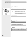
Preparation for Outdoor Unit Installation
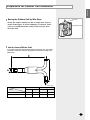
Moving the Outdoor Unit by Wire Rope
Wire rope
Fasten the outdoor unit by two 8m or longer wire ropes as
shown at the figure. To protect damage or scratches, insert
a piece of cloth between the outdoor unit and rope, then
move the unit.
Plate protection cloth
How to choose Refnet Joint
If you want to connect several indoor units to one outdoor unit, you should
purchase a refnet joint. Select an appropriate refnet joint according to the
table below.
(Unit : mm)
Dimension
Model
Inner Diameter
Length
A
B
C
D
-
-
-
-
-
-
-
-
-
-
E-5
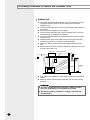
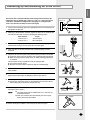
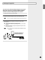
Deciding on Where to Install the Outdoor Unit
Outdoor Unit
◆ The outdoor unit must NEVER be placed on its side or upside down, as the
compressor lubrication oil will run into the cooling circuit and seriously
damage the unit.
◆ Choose a location that is dry and sunny, but not exposed to direct sunlight or
strong winds.
◆ Do not block any passageways or thoroughfares.
◆ Choose a location where the noise of the air conditioner when running and
the discharged air do not disturb any neighbours.
◆ Choose a position that enables the pipes and cables to be easily connected
to the indoor unit.
◆ Install the outdoor unit on a flat, stable surface that can support its weight
and does not generate any unnecessary noise and vibration.
◆ Position the outdoor unit so that the air flow is directed towards the open
area.
◆ Maintain sufficient clearance around the outdoor unit, especially from a radio,
computer, stereo system, etc.
Indoor Unit
Remote Controller
1m or m
ore
1m or more
Fuse
ore
1.5m or m
Fuse
re
mo
or
re
m
mo
1.5
or
m
1.5
or
1.5m
more
Outdoor
Unit
Stereo
◆ If the outdoor unit is installed at a height, ensure that its base is firmly fixed in
position.
◆ Make sure that the water dripping from the drain hose runs away correctly
and safely.
CAUTION
◆ You have just purchased a system air conditioner and it
has been installed by your installation specialist.
◆ This device must be installed according to the national
electrical rules.
E-6
ENGLISH
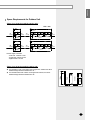
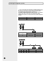
Space Requirements for Outdoor Unit
If there is no obstacle around the outdoor unit...
Unit : mm
300
or more
100
or more
500
or more
Front
300
or more
100
or more
100
or more
500
or more
Front
100
or more
Front
100
or more
100
or more
100 or more
300
100
or more
500
or more
100
" or more
100
or more
500
or more
200
or more
Front
200
or more
100
or more
❋ Max. height of obstacle
- Front side : 1500mm or less
- Air inlet side : 500mm or less
- Right/Left side : No limit
500mm
h2
S1
Air inlet
Front
1500mm
◆ If an obstacle in front of the outdoor unit is higher than 1500mm the half of
additional height should be added to the S1.
◆ If an obstacle behind the outdoor unit is higher than 500mm, the half of
additional height should be added to the S2.
h1
If there is an obstacle around the outdoor unit...
S2
E-7
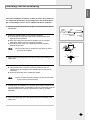
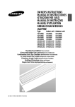
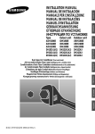
Deciding on Where to Install the Outdoor Unit (cont.)
Respect the clearances and maximum lengths indicated in the diagram below when installing the unit.
Liquid Refrigerant tube
Gas Refrigerant tube
Total Length
(50 metres maximum)
Height
(30 metres
maximum)
Drain hose
E-8
ENGLISH
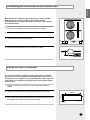
Connecting the Drain Hose to the Outdoor Unit
When using the air conditioner in the heating mode, ice may accumulate.
During de-icing, the condensed water must be drained off safely.
Consequently, you must install a drain hose on the outdoor unit, following
the instructions below.
1
Make space more than 50mm between the bottom of the outdoor unit and
the ground for installation of the drain hose, as shown in figure.
2
Insert the drain plug into the hole on the underside of the outdoor unit.
3
Connect the drain hose to the drain plug.
50mm
min.
4
Ensure that the drained water runs off correctly and safely.
30mm
Fixing the Unit in Position
The outdoor unit must be installed on a rigid and stable base to avoid any
increase in the noise level and vibration, particularly if the outdoor unit is to
be installed close to a neighbour. If it is to be installed in a location exposed to
strong winds or at a height, the unit must be fixed to an appropriate support
(wall or ground).
1
Position the outdoor unit so that the air flow is directed towards the
outside.
2
Attach the outdoor unit to the appropriate support using anchor bolts.
3
If the outdoor unit is exposed to strong winds, install shield plates around
the outdoor unit, so that the fan can operate correctly.
415mm
840mm
E-9
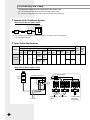
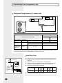
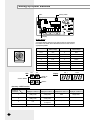
Connecting the Cable
Two electronic cables must be connected to the outdoor unit.
◆ The connection cord between indoor unit and outdoor units
◆ The power cable between outdoor unit and auxiliary circuit breaker.
Example of Air Conditioner System
When using an ELB for 3 phase 4 wires
Outdoor Unit
ELB
❋ If an outdoor unit is installed in a place in danger of an electric leak or submergence,
you must install the ELB.
Power Cable Specifications
Power Supply
Power Max/Min
Supply (V) MCCB
UH175GCM
UH175GZM
Single Phase
3 Phase
Model
380415V~
/50Hz,
3Ø
-
30A
ELB
Power
Cable
Power Max/Min
Length Supply
(V) MCCB
H07RN-F,
5G, 3.5mm2
10m
or less
H07RN-F,
5G, 4.0mm2
10m~
20m
30A
-
-
-
ELB
Power
Cable
Length
-
-
-
Earth CommuCable nication
Cable
-
-
-
-
❋ The power cable is not supplied with air conditioner.
When using an ELB for 3 phase 4 wires
Power Supply
MCCB
High Pressure Switch
Electrical component box
3 Phase
4 Wires
ELB
Connector
MCCB
Fuse
A
B
Cable
clamp
Indoor Unit
E-10
Communication Connection cord
Cable
3 Phase 4 Wires
Power Cable
(AC 380-415V)
ENGLISH
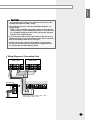
CAUTION
◆ You should connect the power cable into the power cable
terminal and fasten it with a clamp.
◆ The unbalanced power must be maintained within 2% of
supply rating.
- If the power is unbalanced greatly, it may shorten the life
of the condenser. If the unbalanced power is exceeded over
4% of supply rating, the indoor unit is protected, stopped
and the error mode indicates.
◆ To protect the product from water and possible shock, you
should keep the power cable and the connection cord of the
indoor and outdoor units in the iron pipe.
◆ Connect the power cable to the auxiliary circuit breaker.
An all pole disconnection from the power supply must be
incorporated in the fixed wiring(≥3mm).
Wiring Diagram of Connection Cord
Indoor Unit 1
Indoor Unit 2
Outdoor Unit
- Max. length of communication cable : 120m
- Whole length of cable : 240m
E-11
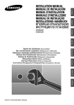
Connecting the Refrigerant Pipe
Refrigerant Piping System (i.e. 2 indoor units)
H2
H1
L2
L1
Refnet joint
L0
Model
Refrigerant piping system table
-
-
-
-
Max. allowable
length
Actual pipe
length
L0+L1(L1≥L2) or L0+L2(L1≤L2)
Allowable
height length
Actual pipe
length
Between outdoor unit and indoor unit (H1)
Between indoor units (H2)
-
Max. difference
in length after
branching
Difference in
length
I L1 - L2 I
-
❋ You had better make piping length from the refnet joint to indoor unit equal with the other ( L1=L2 ).
❋ It is recommended there is no height difference between indoor units.
Install the oil trap
Outdoor Unit
R
Oil trap
(gas pipe:
must be
installed every
10m)
H
Refnet joint
Indoor unit
◆ Install the oil trap in case that the outdoor unit is situated higher than the
indoor unit.
◆ Install the oil trap only in the gas pipe for cooling operation.
◆ Install the oil trap only between the outdoor unit and the first refnet joint.
In this case, it must be installed every 10m from the outdoor unit.
◆ The radius of curvature(R) is as followings.
(Unit : mm)
The diameter of
the gas pipe(D)
The radius of
curvature(R)
12.70
15.88
19.05
22.23
28.60
31.75
38
41
51
57
60
25
32
or more or more or more or more or more or more or more
◆ The height of the oil trap(H) : 4R ≤ H ≤ 6R
E-12
25.40
ENGLISH
Connecting Up and Removing Air In the Circuit
The air in the indoor unit and in the pipe must be purged. If air remains in the
refrigeration pipes, it will affect the compressor, reduce to cooling capacity and
could lead to a malfunction. Refrigerant for air purging is not charged in the
outdoor unit. Use Vacuum Pump as shown at the figure.
1
Connect each assembly pipe to the appropriate valve on the outdoor unit
and tighten the flare nut.
2
Referring to the illustration opposite, tighten the flare nut on section B first
manually and then with a wrench, applying the following torque.
Outer Diameter
9.52 mm (3/8")
19.05 mm (3/4")
Outdoor unit
A
C
B
D
Torque
333~407 kgf•cm
990~1210 kgf•cm
3
Connect the charging hose of low pressure side of manifold gauge to the
packed valve having a service port as shown at the figure.
4
Open the valve of the low pressure side of manifold gauge counterclockwise.
5
Purge the air from the system using vacuum pump for about 10 minutes.
◆ Close the valve of the low pressure side of manifold gauge clockwise.
◆ Make sure that pressure gauge show -0.1MPa(-76cmHg) after about
10 minutes.
This procedure is very important in order to avoid gas leak.
◆ Turn off the vacuum pump.
◆ Remove the hose of the low pressure side of manifold gauge.
6
Set valve cork of both liquid side and gas side of packed valve to the
open position.
7
Mount the valve stem nuts and the service port cap to the valve, and
tighten them at the torque of 183kgf•cm with a torque wrench.
8
Check for gas leakage.
◆ At this time, especially check for gas leakage from the 3-way valve’s
stem nuts(A port), and from the service port cap.
9
If necessary, install the refnet joint horizontally or vertically ; for choice of the
refnet joint, refer to page 5.
Vacuum
pump
B(liquid)
Valve stem
30°
30°
Horizontal
Note
◆ The refnet joint should be installed within 15° or less from the
horizontal/vertical line.
◆ When you install the refnet joint vertically, the inlet of a joint
(Part A) should face downwards.
Vertical
Cable-tie
10 Fix the refnet joint insulation to the refnet joint as shown at figure.
E-13
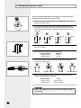
Cutting/Flaring the Pipes
Connect the pipe within 50m and cutting pieces will not be gone
into the pipe as being clean to pipe section.
1
Make sure that you have the required tools available (pipe cutter, reamer,
flaring tool and pipe holder).
2
If you wish to shorten the pipes, cut it with a pipe cutter, taking care to
ensure that the cut edge remains at a 90° angle with the side of the pipe.
Refer to the illustrations below for examples of edges cut correctly and
incorrectly.
O
90
Oblique
Rough
Burr
3
To prevent any gas from leaking out, remove all burrs at the cut edge of the
pipe, using a reamer.
4
Slide a flare nut on to the pipe and modify the flare.
Outer Diameter(D)
9.52 mm (3/8")
19.05 mm (3/4")
5
Check that the flaring is correct, referring to the illustrations below for
examples of incorrect flaring.
Inclined
6
Depth (A)
1.8 mm
2.2 mm
Damaged Surface
Cracked
Uneven Thickness
Align the pipes and tighten the flare nuts first manually and then with
a wrench, applying the following torque.
Outer Diameter
9.52 mm (3/8")
19.05 mm (3/4")
Torque
333~407 kgf•cm
990~1210 kgf•cm
CAUTION
◆ In case of welding the pipe, you must weld with nitrogen
gas blowing.
E-14
ENGLISH
Performing Leak Tests
Before completing the installation (insulation of the hose and piping),
you must check that there are no gas leaks.
To check for gas leaks on the...
Then, using a leak detector,
check the...
Indoor unit
Flare nuts at the end of sections A
and B.
Outdoor unit
Valves on sections C and D.
B
A
D
C
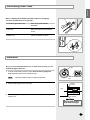
Insulation
Once you have checked that there are no leaks in the system, you can
insulate the piping and hose.
1
To avoid condensation problems, place heat-resistant polyethylene
foam separately around each refrigerant pipe.
Note
2
No gap
◆ Always make the seam of pipes face upwards.
Heat resistant polyethylene
foam
Wind insulating tape around the pipes.
Insulation
cover pipe
Body
3
Finish wrapping insulating tape around the rest of the pipes leading to the
outdoor unit.
Be sure to overlap
the insulation
CAUTION
Must fit tightly against
body without any gap.
E-15
Using Stop Valve
To Open the Stop Valve
Cap
Service
port
1
Open the cap and turn the stop valve counterclockwise by using a hexagonal
wrench.
2
Turn it until the axis is stopped.
Note
Axis
Sealing
point
◆ Do not apply excessive force to the stop valve and always use
special instruments. Otherwise, the stopping box can be
damaged and the back sheet can leaks.
◆ If the watertight sheet leaks, turn the axis back by half, tighten
the stopping box, then check the leakage again. If there is no
leakage any more, tighten the axis entirely.
3
Tighten the cap securely.
To Close the Stop Valve
1
Remove the cap.
2
Turn the stop valve clockwise by using a hexagonal wrench.
3
Tighten the axis until the valve reached the sealing point.
4
Tighten the cap securely.
CAUTION
◆ When you use the service port, always use a charging hose, too.
◆ Check the leakage of refrigerant gas after tightening the cap.
◆ Must use a spanner and wrench when you open/tighten the stop valve.
E-16
ENGLISH
Adding Refrigerant
The outdoor unit is loaded with sufficient refrigerant for the standard
piping. Thus, refrigerant must be added if the piping is lengthened.
This operation can only be performed by a qualified refrigeration
specialist. For quantity of adding refrigerant, refer to page 18.
1
Check that the stop valve is closed entirely.
2
Charge the refrigerant through the service port of liquid stop valve.
Note
3
◆ Do not charge the refrigerant through the gas side service port.
If you cannot charge the refrigerant according to the upper steps,
following these:
3-1 Open both liquid stop valve and gas stop valve.
3-2 Operate the air conditioner by pressing the K2 key on the outdoor
unit PCB.
3-3 About 30 minutes later, charge the refrigerant through the service
port of gas stop valve.
Note
◆ If necessary, refer to the pressure table classified by outdoor
temperature.
Outdoor unit
Liquid side stop valve(service port)
Gas side stop valve(service port)
Ref.
Indoor unit
Balance
1
2
Vacuum pump
E-17
Adding Refrigerant (cont.)
How to Calculate the Quantity of Adding Refrigerant
If you have used more than 5m, add "A" of refrigerant for extra meter.
(For maximum piping length and height, refer to page 12)
The quantity of additional refrigerant is variable according to the installation
situation. Thus, make sure the outdoor unit situation before adding
refrigerant. This operation can only be performed by a qualified refrigeration
specialist.
Model
UH175GCM
UH175GZM
“A”
55g/m
45g/m
Refrigerant
R407C
R22
i.e. 1 indoor unit
Additional charging amount
UH175GCM
UH175GZM
0
0
90g={(7-5) x 45g}
110g={(7-5) x 55g}
Piping length
“a”
5m
7m
i.e. 2 indoor units
a
3m
3m
E-18
Piping length
b
c
1m
1m
2m
4m
a+b+c
5m
9m
Additional charging amount
UH175GCM
UH175GZM
0
0
220g={(9-5) x 55g}
180g={(9-5) x 45g}
ENGLISH
Checking Correct Grounding
If the power distribution circuit does not have an earth or the ground does
not comply with specifications, an grounding electrode must be installed.
The corresponding accessories are not supplied with the air conditioner.
1
2
Select an grounding electrode that complies with the specifications given in
the illustration.
Determine a suitable location for the grounding electrode:
◆ In damp hard soil rather than loose sandy or gravel soil that has a
higher grounding resistance
◆ Away from underground structures or facilities, such as gas pipes,
water pipes, telephone lines and underground cables
◆ At least two metres away from a lightening conductor grounding
electrode and its cable
Note
◆ The grounding wire for the telephone line cannot be used to
ground the air conditioner.
3
Finish wrapping insulating tape around the rest of the pipes leading to the
outdoor unit.
4
Install a green/yellow coloured grounding wire:
◆ If the grounding wire is too short, connect an extension lead, in a
mechanical way and wrapping it with insulating tape (do not bury the
connection)
◆ Secure the grounding wire in position with staples
Note
Carbon
plastic
Steel
core
PVC-insulated green/
yellow wire
Terminal M4
To
grounding
screw
50cm
30cm
◆ If the grounding electrode is installed in an area of heavy traffic,
its wire must be connected securely.
5
Carefully check the installation, by measuring the grounding resistance with
a ground resistance tester. If the resistance is above required level, drive the
electrode deeper into the ground or increase the number of grounding
electrodes.
6
Connect the grounding wire to the electrical component box inside of the
outdoor unit.
E-19
Setting Up Option Switches
KEY
Rotary switch
Display
Rotary Switch
You should display that how many indoor units are connected to
the outdoor unit. Refer to the table below, then turn the arrow to
appropriate position.
K2
KEY
Switch No.
Number of
indoor unit(s)
Switch No.
Number of
indoor unit(s)
0 or 1
One
9
Nine
2
Two
A
Ten
3
Three
B
Eleven
4
Four
C
Twelve
5
Five
D
Thirteen
6
Six
E
Fourteen
7
Seven
F
Fifteen
8
Eight
-
-
DIS 1
K4
DIS 2
Display
DISPLAY
MODE
CHECK MODE
RESET
K1
SEG 1
SEG 2
SEG 3
SEG 4
K3
Summary of KEY functions
Number of
press times
Function
K1
K2
K3
K4
(Displayed on SEG 3, 4) (Displayed on SEG 3, 4) (Displayed on SEG 3, 4) (Displayed on SEG 3, 4)
1
Adding refrigerant at
heating mode
Adding refrigerant at
cooling mode
Reset
Displays data
2
Test operation at
heating mode
Test operation at
cooling mode
-
-
3
End
Pump Down for recovery
of refrigerant
-
-
4
-
End
-
-
❊ Use the K1 only for heat pump models.
E-20
ENGLISH
Reading data indicated on the display
KEY
Number of
press
K1
1
Adding refrigerant for heat pump models
2
Test operation for heat pump models
3
End
1
Adding refrigerant for cooling only models
2
Test operation for cooling only models
3
Pump Down for recovery of refrigerant
4
End
K2
K3
K4
Item
Example
Display Meaning
Reset
1
2
110 °C
3
Discharge temperature of compressor
4
Temperature of outdoor heat exchanger
38 °C
5
Outdoor temperature
34 °C
6
Step of electronic expansion valve
(0 step : all closed, 480 step : all open)
7
Temperature of evaporator
120STEP
(12 x 10)
-2 °C
12 °C
8
Indoor temperature
22 °C
9
10
Stopping view mode & display communication data
E-21
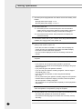
Testing Operations
1
Check the power supply between the outdoor unit and the auxiliary circuit
breaker.
◆ Single phase power supply: L1, L2
◆ Three phase power supply: L1, L2, L3
2
Check the indoor unit.
2-1 Check that you have connected the power and communication
cables correctly. (If the power cable and communication cables one
mixed up or connected incorrectly, the PCB will be damaged.)
2-2 Check the thermistor sensor, drain pump/hose, and display are
connected correctly.
3
Connect the outdoor unit to your computer where the provided software is
installed, then supply power to the outdoor unit.
4
If the outdoor unit is powered on, it will start tracking to check user's
option(s) and number of indoor unit.
- At this time, the SEG 1 and SEG 2 on outdoor unit PCB display the
number of indoor unit registered and the SEG 3 and SEG 4 display
the number of indoor units which responded.
- If an error mode is displayed, fix the error according to the service
manual.
5
Check the thermistor sensor, electronic expansion valve by using the
computer.
6
Press K2 on the outdoor unit PCB.
- If you press K2, the compressor starts operation. Operate the
compressor for 20 minutes, then add refrigerant according to the graph
shown on page 23.
- If you press K2 again, test operation is started.
- If you don't stop the operation of adding refrigerant, it will be stopped
automatically after 1 hour.
- If you don't stop test operation, it will be stopped automatically
after 1 hour.
- If K2 is pressed during the operation of adding refrigerant, test operation
is started without compressor stopping. Therefore, start test operation
after the operation of adding refrigerant.
- The compressor can be operated after completely 3-minute preparation
and tracking.
7
Check that indoor and outdoor temperatures, step of electronic expansion
valve and operation of compressor by using the computer.
8
Check that there is any error mode in the outdoor unit PCB during the test.
- You should test operations for more than 30 minutes.
- Check that the water dripping from the drain hose runs away correctly
and safely.
9
E-22
To complete the test, press the test operation KEY(K2) again.
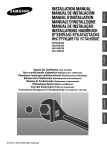
ENGLISH
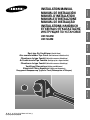
Graph of low/high pressure depending on outdoor temperature
5m (pipe length)
6.0
6.00
50m (pipe length)
5.5
5.0
4.68
4.5
4.44
4.0
3.87
3.65
3.5
3.0
2.81
2.5
2.0
UH175GCM(Heat Pump Mode)
Low pressure (Kgf/cm2G)
Low pressure (Kgf/cm2G)
UH175GCM(Cooling Only Mode)
6.5
5.0
5m (pipe length)
4.0
50m (pipe length)
3.5
3.37
3.0
2.79
2.5
2.15
20
25
30
35
40
45
1.89
1.5 1.24
1.0
0.5
-20
50
-15
-10
-5
29.0
5m (pipe length)
27.0
26.98
50m (pipe length)
26.27
25.0
23.0
21.24
21.0
20.82
19.0
17.28
17.0
15.0
15
16.59
20
25
30
35
40
45
24.0
5.23
5.0
4.82
4.72
4.5
4.16
4.26
4.0
3.5
15
20
25
30
35
40
45
20.94
20.0
18.0
17.36
17.82
16.0 15.14
16.15
14.0
14.15
22.67
22.05
21.0
19.10
19.0
18.78
17.42
17.0
15.0
15
17.11
20
25
30
35
40
45
50
Outdoor temperature
5
10
15
20
25
3.22
5m (pipe length)
3.11
3.0
50m (pipe length)
2.52
2.5
2.35
2.0
1.5
1.26
1.0
1.17
-10
-5
0
5
10
15
Outdoor temperature
UH175GZM(Heat Pump Mode)
High pressure (Kgf/cm2G)
50m (pipe length)
0
3.5
0.5
-15
UH175GZM(Cooling Only Mode)
5m (pipe length)
19.66
18.95
Outdoor temperature
23.0
24.78
23.50
UH175GZM(Heat Pump Mode)
50
25.0
20
Outdoor temperature
Low pressure (Kgf/cm2G)
5.5
5.83
15
50m (pipe length)
22.0
12.0
-20 -15 -10 -5
UH175GZM(Cooling Only Mode)
50m (pipe length)
10
5m (pipe length)
Outdoor temperature
5m (pipe length)
5
UH175GCM(Heat Pump Mode)
50
6.0
0
Outdoor temperature
High pressure (Kgf/cm2G)
High pressure (Kgf/cm2G)
2.44
2.0
1.02
15
UH175GCM(Cooling Only Mode)
Low pressure (Kgf/cm2G)
4.29
3.68
Outdoor temperature
High pressure (Kgf/cm2G)
4.42
4.5
20.0
5m (pipe length)
18.0
50m (pipe length)
18.50
17.70
16.0
14.67
14.45
14.0
12.96
12.81
12.0
-15
-10
-5
0
5
10
15
Outdoor temperature
E-23
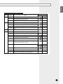
Troubleshooting
Outdoor unit
If an error occurs during the operation, it is displayed on the outdoor unit PCB.
Display
Explanation
High temperature of Discharge (Protection control)
High temperature of outdoor heat exchanger (Protection control)
Remark
Error about protection
control of outdoor unit
COMP DOWN to protect being frozen
Error of momentary power failure (disappears when the unit is Off/On)
Error of Discharge TEMP sensor (OPEN/SHORT)
Errors about outdoor unit
sensor (OPEN/SHORT)
Detection during the
operation of indoor unit
(Sensing and sending errors
into the communication data)
System Down caused by communication error after
completion of tracking
Communication and indoor
unit errors
Error of OUT TEMP sensor (OPEN/SHORT)
Error of temperature sensor in outdoor heat exchanger (OPEN/SHORT)
Mismatching of the indoor unit numbers set with those
communicated after completion of tracking
Error of float switch in indoor unit
Error of setting option switches for optional accessories
x
OPEN/SHORT error of room sensor in indoor unit
x
OPEN/SHORT error of eva in sensor in indoor unit
x
EEPROM option error
x
Error of fan starting
Self-diagnosis of indoor
and outdoor unit (x:indoor
unit address)
Displays of operating status
Open error of electronic expansion valve in outdoor unit
(Detected once or more times)
Close error of electronic expansion valve in outdoor unit
(Detected once or more times)
Flicker
Below -5°C when cooling
Flicker
Over 30°C when heating
K1, K2, K3, K4,
K5 Flicker
The order of priority : E1 → E2 → E4 → E5 → P0 → P1 → P5 → P9 → P6 → t1 → t2 → t3 → tu →
to → G4 → G5 → E3 → qx → rx → vx → K1, K2, K3, K4, K5
- In case that the same error displays from multi-indoor units, the one having the faster address
has the priority.
E-24
ENGLISH
Chapter
OPTIONAL ACCESSORIES
■
Parts List
. . . . . . . . . . . . . . . . . . . . . . . . . . . . . . . . . 26
E-25
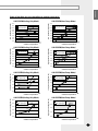
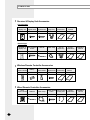
Parts List
Receiver & Display Unit Accessories
Concealed type
Receiver &
display unit
1
STS 2S-2x10
2S-4x12
tapped screw tapped screw
Wire kit
(length 10m)
Owner’s
instructions
Installation
manual
4
2
1
1
1
Receiver &
display unit
M4x16 tapped
screw
Cable-tie
Cable clamp
Wire kit
(length 10m)
Owner’s
instructions
Installation
manual
1
7
2
5
1
1
1
Standard type
Wireless Remote Controller Accessories
Wireless
remote controller
Battery
1
2
Remote
STS 2S-2x10
control holder tapped screw
1
2
Owner’s
instructions
Installation
manual
1
1
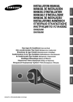
Wired Remote Controller Accessories
E-26
Wired
remote controller
Cable-tie
Cable clamp
1
2
2
M4x16 tapped Indoor unit power
screw
drawing cable
7
1
Owner’s
instructions
Installation
manual
1
1
ENGLISH
Centralized Controller Accessories
Centralized
controller
Cable-tie
Cable clamp
M4x16 tapped
screw
Owner’s
instructions
Installation
manual
1
2
5
7
1
1
Function Controller Accessories
Function
controller
Cable-tie
Cable clamp
M4x16 tapped
screw
Owner’s
instructions
Installation
manual
1
2
6
7
1
1
Transmitter Accessories
Transmitter
Transmitter
power cable
Transmitter communication cable
Installation
manual
1
1
1
1
Note
◆ If you would like to install the centralized controller, you must install the transmitter in the
outdoor unit.
E-27
THIS AIR CONDITIONER IS MANUFACTURED BY:
ESTE AIRE ACONDICIONADO HA SIDO FABRICADO POR:
CE CLIMATISEUR EST FABRIQUE PAR:
QUESTO CONDIZIONATORE D’ARIA È PRODOTTO DA:
ESTE APARELHO DE AR CONDICIONADO É FABRICADO POR:
DIESE KLIMAANLAGE IST FABRIZIERT VON:
AYTH H ™Y™KEYH KATA™KEYA™THKE A¶O:
ùíéí äéçÑàñàéçÖê àáÉéíéÇãÖç îàêåéâ:
ELECTRONICS
Printed in Korea