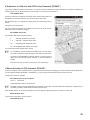
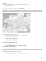
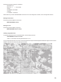
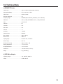
1
OPERATING INSTRUCTIONS Version 07/12 GSM-GPS Tracker with Alarm Function „GX103+GPS“ Item No. 66 24 93 Table of Contents Page 1. Introduction ................................................................................................................................................................................................ 3 2. Intended Use .............................................................................................................................................................................................. 4 3. Explanation of Symbols .............................................................................................................................................................................. 4 4. Scope of Delivery ....................................................................................................................................................................................... 4 5. Safety Information ...................................................................................................................................................................................... 5 6. General Notes on Rechargeable Batteries ................................................................................................................................................. 5 7. General Descriptions .................................................................................................................................................................................. 6 8. Introduction ................................................................................................................................................................................................ 6 a) Description of the Operating Elements .................................................................................................................................................. 6 b) Product Status and Mode ...................................................................................................................................................................... 9 c) Notes on Use ........................................................................................................................................................................................ 9 d) Firmware Update ................................................................................................................................................................................... 9 e) Notes on the Electrical Connection ..................................................................................................................................................... 10 9. Commissioning - First Steps .................................................................................................................................................................... 10 a) Operating voltage ................................................................................................................................................................................ 10 b) Changing the PIN Code to “1513” ....................................................................................................................................................... 10 c) SIM Card Insertion ............................................................................................................................................................................. 11 10. Configuration via Text Message ............................................................................................................................................................... 12 a) General Information ............................................................................................................................................................................ 12 b) Special Commands ............................................................................................................................................................................. 13 11. Functional Descriptions ............................................................................................................................................................................ 14 a) General Configuration Commands ...................................................................................................................................................... 14 1. Changing the PIN Code (Command “PIN”) .................................................................................................................................... 14 2. Changing the Device Name (Command “NAME”) .......................................................................................................................... 14 3. Setting the Language (Command “LANGUAGE”) .......................................................................................................................... 15 4. Setting Time and Date (Command “TIME”) .................................................................................................................................... 15 5. Administration of Phone Book (Command “TEL”) .......................................................................................................................... 16 6. Alarm Sound at Alarm (Command “ALARMSOUND”) .................................................................................................................... 17 7. Speaker Events (Command “SOUNDINFO”) ................................................................................................................................. 18 8. Changing the Calling Sound and Volume Settings (Command “AUDIO”) ...................................................................................... 18 9. Time Setting Alarm Activation/Deactivation (Command “COUNTDOWN”) ..................................................................................... 19 b) In- and Outputs ................................................................................................................................................................................... 20 1. Configuration of the Sensors (Commands “SHOCK”, “MOVE”, “VOICE”) ...................................................................................... 20 2. Setting Support (Command “DIAGNOSIS”) ................................................................................................................................... 21 3. External Voltage Source / USB Plug Monitor (USB) ....................................................................................................................... 21 4. Assigning Functions to the Buttons “1”, “2” and “3” (Commands “KEY1”, “KEY2”, “KEY3”, “KEYALL”) .......................................... 21 c) Additional Functions ............................................................................................................................................................................ 23 1. Recall in Case of Alarm (Function “RECALL”) ................................................................................................................................ 23 2. Reaction at Incoming Call (“INCALL”) ............................................................................................................................................ 23 3. Lifesign (Function “ALIVE”) ............................................................................................................................................................ 25 12. Configure Expansions .............................................................................................................................................................................. 26 2 Page 13. Position Determination ............................................................................................................................................................................. 27 a) General GPS Localisation (Command “GPS”) .................................................................................................................................... 27 b) Submission of a Web Link with GPS Position (Command “GPSMAP”) ............................................................................................... 28 c) Manual Activation of GPS (Command “GPSLIVE”) ............................................................................................................................. 28 d) Activate Position Tracking (Command “TRACK”) ................................................................................................................................ 29 e) Programming the GPS Zone (Command “GPSZONE”) ...................................................................................................................... 30 14. System Functions ..................................................................................................................................................................................... 32 a) Time between Two Alarm Messages (Command “IDLEALARM”) ....................................................................................................... 32 b) Resetting to Default (Command “RESET SETUP”) ............................................................................................................................. 32 15. Factory Settings ....................................................................................................................................................................................... 33 16. Disposal ................................................................................................................................................................................................... 33 a) General Information ............................................................................................................................................................................ 33 b) Batteries and Rechargeable Batteries ................................................................................................................................................. 33 17. Declaration of Conformity (DOC) ............................................................................................................................................................. 33 18. Technical Data ......................................................................................................................................................................................... 34 a) GSM+GPS-Tracker ............................................................................................................................................................................. 34 b) USB Mains Adapter ............................................................................................................................................................................. 34 1. Introduction Dear Customer, Thank you for purchasing this product. This product complies with the statutory national and European requirements. These operating instructions are part of this product. They contain important notes on commissioning and handling. Also consider this if you pass on the product to any third party. Therefore, retain these operating instructions for reference! All company names and product names are trademarks of their respective owners. All rights reserved. If there are any technical questions, contact: Tel. no.: +49 9604 / 40 88 80 Fax. no.: +49 9604 / 40 88 48 E-mail: [email protected] Mon. to Thur. 8.00am to 4.30pm, Fri. 8.00am to 2.00pm 3 2. Intended Use The product serves to monitor your property. To secure your property, sensors like vibration, motion detectors (PIR), microphone and a GPS receiver are available. The integrated GPS receiver serves precise determination of the position, GeoFence monitoring and tracking of movements. The product must not be user to monitor persons. The product is designed for the home area and must only be used under the corresponding conditions. All functions can be controlled remotely by text message. This product can also be used as a simple phone. This function, however, has to be configured separately. Any other use than described before is not intended and may cause loss of warranty/guarantee. The customer is responsible for application of the product in accordance with the law. Conrad Electronic does not assume any responsibility/ liability exceeding application of the product as described here. No part of this product must be modified or converted. Observe all safety information in these operating instructions. They contain important information on handling of the product. You should also heed the additional safety instructions in each chapter of these instructions. 3. Explanation of Symbols This symbol is used when your health is at risk, e.g. from an electric shock. The symbol with the exclamation mark points out particular dangers associated with handling, function or operation. The “Hand” symbol indicates special advice and operating information. 4. Scope of Delivery • GX103+GPS with integrated rechargeable battery • USB Mains Adapter • Short description • Operating instructions on CD 4 5. Safety Information The guarantee/warranty will expire if damage is incurred resulting from non-compliance with these operating instructions. We do not assume liability for any consequential damage. Nor do we assume any liability for damage to property or personal injury caused by improper use or failure to observe the safety information. In such cases the warranty/guarantee will expire. • The unauthorized conversion and/or modification of the product is prohibited for safety and approval reasons (CE). • The product is not a toy. Devices that are operated with mains voltage have no place in the hands of children. Therefore, be particularly careful when children are present. Operate the product in a way that it is out of reach of children. • The system only serves to trigger alarms but does not relieve the user from his diligence obligation. • The GPS functions only serve to monitor property. The customer is personally responsible for compliance with the statutory requirements for further monitoring. • Avoid strong mechanical strain on the system components. • Do not expose the device to any high temperatures, dripping or splashing water, strong vibrations or heavy mechanical stress. • The product is only suitable for operation in dry, closed rooms. The entire product must not become damp or wet. The USB mains adapter otherwise poses danger of potentially fatal electric shock! • The USB mains adapter is constructed pursuant to protection category II. Only a proper mains socket must be used as voltage source for the USB mains adapter. • If the USB mains adapter is damaged, do not touch it. Danger to life from electric shock! First switch off the mains voltage for the mains socket to which the USB mains adapter is connected (switch off the corresponding circuit breaker or turn out the fuse, then switch off the FI protection switch so that the mains socket is separated from the mains voltage on all poles). Then unplug the USB mains adapter from the mains socket. Dispose of the damaged USB mains adapter in an environmentally compatible way. Do not use it anymore. Replace it with a new USB mains adapter of the same specifications. • Do not leave packaging material unattended. It may become a dangerous toy for children. • Handle the product with care; impacts, shock or fall even from low heights will damage it. • If you are not sure about the correct connection or if there are any questions that are not covered by the operating instructions, do not hesitate to contact our technical support or another specialist. 6. General Notes on Rechargeable Batteries • Keep the rechargeable battery out of reach of children. • Leaking or damaged batteries/rechargeable batteries can cause chemical burns to skin when touched without the use of adequate protective gloves! • The rechargeable battery must never be short-circuited or thrown into fire. There is a risk of fire and explosion! • Never take the battery apart! • If the rechargeable battery heats up strongly when charging, interrupt the charging process! • Never charge the battery unobserved. • For reasons of safety, only charge the rechargeable battery on a heat-resistant surface. • If the rechargeable battery shows any deformation, holes or other obvious defects, no longer use the rechargeable battery and do not try to charge it. • Dispose of the rechargeable battery environmentally compatibly. 5 7. General Descriptions This product is to be used to monitor the customer’s property. In case of alarm, its primary task is in informing the customer of it as quickly as possible by text message. Scaring off by an alarm sound is an addition option that must be configured. Vibrations can be monitored, living beings recognised with the integrated motion detector and noises determined. In case of alarm, the GX103+GPS sends an alarm text message to up to 6 saved phone number and is able to call back a phone number afterwards(optionally with the speaker deactivated, silent mode). The customer may at any time perform other actions by sending text message from his mobile phone, e.g. determine the current GPS position (coordination or web link), request the status, or perform a “silent call” to hear what is currently taking place in the monitored area. The microphone or speaker can be used to accept calls and call pre-set phone numbers. The update function can be used to give the device new functions that Conrad Electronic provides in the scope of product improvements. The GPS receiver is used to determine and monitor GPS zones (Area, GeoFence), i.e. places where the product may be present. The product is secured against manipulation with an internal battery. This product is not a common phone. The sensors and GPS function increase the functional scope and thus also complexity. In the following, the most important items that you should observe when using the product are noted. These instructions assume the functional scope at the time of initial delivery. The option of the firmware update may add new functions via the USB interface. Visit the website on this product from time to time on our website www.conrad.com, where you may find new firmware and revised operating instructions. All text message answer examples are to be understood symbolically. Actual implementation may vary. The examples should only show the information to be expected, their format and writing. 8. Introduction a) Description of the Operating Elements 1 GPS LED 2 Speakers 3 GPS receiver position 4 Battery LED 5 GSM LED 6 Button for “Alarm Enable/Disable” 7 On/off button 8 Button “1” (“KEY1” and hang up) 9 Button “2” (“KEY2” and speaker) 10 Button “3” (“KEY3” and accept) 11 Microphone (phone and VOICE) 12 Motion sensor (PIR) 13 Plug-in socket for extensions (EXTERN) 14 USB socket 15 SIM card holder 16 Button for reset 6 GSM LED (5): This LED shows the current GSM status. For this, the LED has the following presentation options: • LED is lit green = Searching for GSM network • LED flashes green (every 1 s) = Device registered at the GSM network • LED flashes green (every 1/2 s) = call / phone connection • LED flashes red/green = no GSM network connection / PIN error / invalid SIM card / PUK / … • LED off = no power supply present / product off When the product is charged via the USB socket without any SIM card inserted, the green LED is displayed. Since this LED is controlled right by the GSM module and the GSM module was switched off entirely (switch in the SIM card holder), this LED may be lit by accident. Without SIM card, the GSM module is definitely off and will not try to log on to the GSM network. Battery LED (4): The internal battery is charged and managed via a separate hardware. Thus, the battery can also be charged when no SIM card is inserted and the entire GSM hardware is deactivated. This LED provides the following information: • LED is lit red: The battery is being charged • LED is lit green: The battery is charged completely • LED is lit orange (red and green at once): An error was recognised (e.g. no battery present) • LED off = no USB voltage present GPS status LED (1): This LED is used to recognise the activity and status of the GPS receiver. The following display options are available for this: • LED flashes blue: Current GPS position determined correctly • LED is lit blue: GPS position not determined or determinable • LED off: GPS module is in sleeper mode / switched off The GPS receiver is on the front, right below the GPS-LED. Important note on accuracy of GPS positions: Accuracy of the GPS position determined depends on many factors. Since the GX103+GPS leaves the GPS receiver off at all times for runtime reasons in battery-powered operation, this will negatively influence accuracy. The GPS signal as such is overlaid by correction data that are saved in the device and will accelerate, among others, satellite search. Therefore, we recommend that the product is left to assess the GPS positions for a few minutes if there are any problems with accuracy. This procedure is called “tracking”. It should reduce the deviation to regular GPS accuracy. For this, observe the description on the command “TRACK” LEDs in the buttons “1”, “2” and “3” (8/9/10): These LEDs have various functions. The primary task is showing the current status behind the function that was linked to the corresponding button. If, e.g., the motion detection was configured behind button “1” (“MOVE”), pushing this button will activate the alarm sensor with its last settings (can be recognised by the activated LED). Another push of the button will switch off this function and therefore the LED again. Since the buttons have different functions in the “CALL” mode, the function described above only applies in regular mode (in which the alarm is deactivated). 7 Left button (6): This button switches the alarm mode of the product. The change is triggered only after pushing and holding the button for a few seconds. Depending on configuration (see function description on the command “COUNTDOWN”), a countdown signal is generated upon activation to give the user some time to leave the sensor range. After an alarm incident is recognised, there will be a waiting time of some seconds to enable the user to switch it off. Right button (7): This switches the device on or off. The reaction to pushing a button takes place only after pushing and holding it for a few seconds. Button 1, 2, 3 (8/9/10): These buttons have no function in the “ALARM ENABLE” mode. In regular condition, these buttons can be set freely. The functions these buttons can be assigned are shown in the chapter on the function description for the “KEY” command. For example, a phone number to be called can be stored on these buttons, or they can be used to switch the sensor on and off. The buttons have the following functions during a phone call: • The button “1” (8) serves to hand up or reject a phone call. • Use the button “2” (9) activates and deactivates the speaker. • Use the button “3” (10) accepts a call. The product can only be called when this was set accordingly in the “INCALL” command. USB socket (14): This USB socket is used to load the product. No SIM card is required for this. Additionally, permanent operation via USB is intended. Connected to the PC, a driver is needed for the “virtual COM port” so that the product can be configured via USB and a firmware update performed. The required software and firmware files are available online at www.conrad.com, in the download section for the product. Use of the product with another software than the one released there officially is not intended and may limit the warranty/guarantee. Additional safety notes apply for firmware updates. They are displayed briefly before execution in the firmware update software. Permanent operation using a USB po0wer supply is intended but not possible right at the PC. The USB bridge chip internally shares the same port as the GPS receiver; therefore, the GPS receiver will not work wile the device communicates with the PC. Therefore, use of the external USB mains adapter is recommended. Speaker (2) and microphone (11): The installed speaker also serves to play back alarm and ring tomes and hands-free function. Two microphones are installed. The first microphone is needed for talking and directly connected to the GSM module. The second microphone is used for sound level measurement and issues an alarm when the alarm threshold value set (sound level) is exceeded. The two microphones are located next to each other in the same position. Extension port (13): This 2.5 mm jack socket serves to later expand the product with various accessories. For more information on this, see the product website at www.conrad.com. No headset, headphones or other devices with jack plug must be connected to this jack socket. There is a danger of the irreparable damage to the product and the connected device. 8 b) Product Status and Mode The product has the following modes: “Alarm Enable”: This mode is entered by the text message command “ALARM ENABLE”, pushing and holding the left button and, depending on configuration, e.g. via a call. Whether or not the alarm is active can only be seen by a status text message. Only in this mode can the product send text messages independently and without any customer interaction, and perform a recall - depending on configuration. This only takes place when an activated alarm source recognises an alarm incident (vibration, PIR, microphone, etc.). Only in this case, all phone numbers in the device phonebook (not that of the SIM card) will receive the corresponding alarm text message. “Alarm Disable” (regular mode): This mode is also designated the “regular mode” that is entered after the product is switched on. In this mode, GSM costs may only arise when customer interaction triggers it. The product only sends out text messages when a text message with the correct PIN was received first. The device will only call on direct command anymore (button,...) from the customer. The product then also cannot trigger an alarm. Call (incoming): The product’s reaction to an incoming call is defined by the function “INCALL”. The basic setting is rejecting the call to save energy. To be able to use the product as a phone, for example, the “INCALL” function must be set in the mode “CALL”. For more information on this, see the corresponding chapter. USB connection: While a USB connection is active (i.e. with data communication to the PC), the GPS-receiver cannot be used. For a passive USB-connection, in contrast (e.g. when connecting the device to a USB mains adapter), the GPS receiver remains active at all times. The remaining functions are not affected by any USB connection. c) Notes on Use • There is no prescribed usage position. • When using the USB or jack socket, observe that there is enough place for the plugs. Lateral forces on the plugged-in plugs can lever the sockets from the PCB and thus cause irreparable damage, loss of warranty/guarantee! • To ensure the device function, choose a usage site where the GMS network reception is as good as possible. • The setup site should be protected against overheating of the device, excessive moisture and dust. • The product should be taken to a site where object vibration can be measured (for use of the vibration alarm). • The product must not be subject to continuous strong vibrations (vibrating machines, direct motor/chassis contact). • The product is not protected against weather and therefore must be installed inside. d) Firmware Update A firmware update is performed via the USB interface at a PC with Windows operating system. For this, the PC software for the product is needed that can be found in the download area for the product at www.conrad.com. • New firmware versions are a voluntary service by Conrad Electronic SE and its partners and mainly serve product maintenance. There is no legal claim to this. • Performance of a firmware update is connected to a certain risk. If the transmission is interfered with during the update process, this may cause the module to no longer function (including update function). In this case, the customer must return the product to the customer service with the note “FULL FIRMWARE UPDATE”. The costs for a firmware update must be assumed by the customer. Whether any costs arise and how high they are is indicated in a previous cost estimate. 9 e) Notes on the Electrical Connection • The external cables must be kept as short as possible and remaining line lengths must not be coiled. • Too-strong temperature fluctuations may lead to temporary impairment and require manual reset in extreme cases. • The product is not intended for the “Safety” area and also does not correspond to any SIL/ASIL level. 9. Commissioning - First Steps The following is needed for operation and configuration of the device: • A common mobile phone with SIM card • An additional SIM card (prepaid or contract) for the device • A USB port (PC, or included USB mains adapter) a) Operating Voltage The product should be connected to the USB mains adapter for testing. The battery LED shows whether the operating voltage was connected correctly, no matter the device status: LED off = no external voltage supply present LED is lit green/red/orange = external voltage supply present An unloaded battery in combination with bad GSM reception may lead to the module having to switch off in spite of USB connection to protect the internal battery against deep discharge. If such behaviour occurs during the test, wait for a few minutes until the battery was sufficiently loaded to be able to deliver the energy for the GSM module. The GPS receiver is deactivated ruing a connection to a PC. When this function is required, connect the device to the USB mains adapter rather than the USB port of a PC. GPS reception in building sis only possible when the device is placed right by the window, so that there is a free view of the sky and therefore the GPS satellites. b) Changing the PIN Code to “1513” Every SIM card has a PIN code. Because this GSM product uses its own PIN processing, the SIM card PIN code must be changed to that of the product. The following steps are required for this: • The SIM card intended for the product must be inserted in any mobile phone. • According to the operating instructions of the mobile phone, the PIN code must be changed to “1513”. • The SIM card with the changed PIN code must be removed from the mobile phone. • The SIM card with the changed PIN code can now be inserted in the intended device slot (see next chapter). 10 c) SIM Card Insertion • The SIM card with the PIN number “1513” must be inserted in the device as shown in the following. • When the SIM card is inserted, the product is still switched off. To switch it on, push the “On/off” button (7) for a few seconds until the GSM LED lights up. First, the GSM LED is lit green (GSM network search); after a few seconds, the LED should start flashing (GSM network found, device ready for operation). If the green LED does not start to flash, there is no connection to the GSM network. In this case, the network quality and function of the SIM card must be inspected at the product site with a separate mobile phone. If the LED flashes red, there is an error when connecting to the GSM provider or the PIN number is incorrect. In this case, the device must be reset to factory settings. Furthermore, the SIM card (PIN/PUK/activation) must be inspected and the receiver quality at the device position must be verified with a separate mobile phone. • If the device used to be used with another SIM card, there is the option of the PIN number in the product being changed and now no longer matching the default setting “1513”. In this case, reset the device to factory settings (section “Factory Reset”) and manually set the SIM card PIN in your mobile phone to “1513”. • The SIM card may have been locked in the meantime and must be unlocked with the PUK. 11 10. Configuration via Text Message a) General Information To receive the full functional scope of the product, it must be configured first. The entire configuration is performed by simple text message commands you send to the device (the phone number of the SIM card in the device) from your mobile phone. This method makes it possible to activate, deactivate or change the settings of your device from anywhere. Alternatively, the product can be configured via the USB interface using PC software. These operating instructions do not deal with the PC software configuration. This only describes how the product can be controlled with a mobile phone only, without any other aids. To protect from unauthorised access, the product generally reacts to authenticated messages only. In a text message, you authenticate yourself by including the correct PIN number (not the one of the mobile phone from which the text message was written). When calling, the conveyed phone number must correspond to a phone number in the phone book. Caution, important! For your own safety, the PIN number must be changed under all circumstances after commissioning of the product. This is described in more detail in the chapter corresponding to the command. Introduction to the Command Format: The text message to programme the device is set up according to the following chart, observe the examples: <ACTION> <FUNCTION> <PARAMETER1> SET TEL1 +49177556644221 RESET TEST <…> <#PIN> #1513 (phone book) INCALL #1513 (no calls) IN1 #1513 (request IN1) Important! Every text message sent to the device must end with the PIN set as protection. Without “#PIN” at the end of the text message, it is discarded and no answering text message will be generated! The individual words and parameters must be separated by a space each. <ACTION>: The following action can be determined: SET = switch on/activate/configure RESET = switch off/deactivate/default settings TEST = test/check/request <FUNCTION>: This is used to select the function you want to change or perform: TEL1 = phone book entry no. 1 Name = Device name INCALL = Setting for incoming call <PARAMETER>: Both the presence and the number of parameters depend on the function and action used. Therefore, most “RESET” actions have no parameters while “SET” actions (what should be set to which value) without any parameters are rather rare. 12 A parameter may be the following: List: The customer may choose a parameter from a pre-defined list, e.g.: DE, EN, LH, HL, LHL,… Writing: <DE/EN>, <LH/HL/LHL/..> Number: An integer without decimal digits, optionally with prefix, e.g.: 5 = time [sec.] (SET IN1 LH 5 #1513) Writing: <TIME> TIME = xxx to xxx, xxx = …. Examples: (if the PIN of the device “ is 1513): SET INCALL CALL #1513 Callers are admitted (observe phone book) SET MOVE 5 #1513 Activation motion detector with medium sensitivity. Note on the RESET command: If a function is to be switched off or reset due to an error, the corresponding “RESET” action must be used with the corresponding function word! This action is universally applicable for all functions/text message commands and resets the corresponding function to the default value. Example: RESET INCALL #1513 All incoming calls are rejected. Capitalisation is not relevant; you may use capital and small letters as you wish. Every new command of the same function (2nd word) will overwrite the previous settings. After every text message command, the device will return a test message answer to confirm the programming (if the PIN in the text message command was correct and the phone number is conveyed). b) Special Commands There are commands that are so important that they deviate from the command format from the previous chapter on purpose. These commands are: ALARM ENABLE #1513 ALARM ENABLE #1513 This command is used to switch the alarm mode on or off. The effects this has on the product behaviour were already described in the corresponding chapter 8. b) “Status and Mode”. STATUS #1513 This command returns a summary of the most important settings and conditions of the device. Example (deviations possible depending on firmware version): Answer: GX103_GPS 1.08 Alarm: off Batt: 100% GSM: 59% GPS: on Area: off Move: off Shock: off Voice: off USB: off Product name, firmware version Alarm deactivated (function “DISABLE”) Status of the rechargeable battery GSM signal strength Status GPS receiver Zone monitoring / GeoFence (function “AREA”) off Motion detector off Acceleration sensor off Microphone monitoring off Status Voltage monitoring off 13 11. Functional Descriptions In the following examples, it is assumed that the PIN of the SIM card in the device is “1513”. a) General Configuration Commands 1. Changing the PIN Code (Command “PIN”) To secure the product from unauthorised access, the standard PIN “1513” may be set to any other value. Change the PIN code as follows: SET PIN <new PIN> #<old PIN> Example: Changing old PIN 1513 to new PIN 1234: SET PIN 1234 #1513 For every new text message command, the new PIN code now has to be appended preceded by a (#) sign. If the wrong PIN code is entered or the PIN code is not sent, you will not receive an answering text message. Changing of the PIN code will change both the settings of the product and the PIN code of the SIM card! The PIN code always has 4 figures. When the PIN code is lost (lost or forgotten), the product can be reset to factory settings (see chapter “Factory Settings”). All programming will be lost when resetting! Then the device must be programmed again. Resetting the device to factory settings will not affect the SIM card. The SIM card PIN is retained. 2. Changing the Device Name (Command “NAME”) If several products are operated at the same time, it is recommended to assign a different name to each device. This makes it possible to assign alarm messages to the correct device. The device name has a maximum length of 15 characters. Do not use any spaces or special characters. To change the name at your device, send the following text message command: SET NAME <new name> #1513 Example: Renaming to “NEWNAME”: SET NAME NEWNAME #1513 Confirmation text message: NEWNAME 1.xx ... ... Factory reset: RESET NAME #1513 There is no TEST action for this function. 14 3. Setting the language (Command “LANGUAGE”) This command sets the product langauge. SET LANGUAGE <DE/EN> #1513 Example: SET LANGUAGE DE #1513 This command is needed to reset to German: RESET LANGUAGE #1513 There is no TEST command for this command. 4. Setting Time and Date (Command “TIME”) The product offers time and date settings. This way, the precise time and date at which the text message was generated is stored in the text message, independently of when the text message was sent or received. Various functions also require the current time and date. SET TIME <hh mm dd mm yy> #1513 Hour Minute Day Month Year (0-23) (0-60) (1-31) (1-12) (0-95) Example: 18:22 hours, 24.03.2012 SET TIME 18 22 02 04 12 #1513 time Example of a text message response: GX103_GPS 1.08 Time: 18:22 Date: 02.04.12 Mo GPS: on Status: off Protective time: not specified Alarm every 7 min GPS: 60 min Alarm en. delay: 15s Alarm delay: 0s To check the current time, use the following command: TEST TIME #1513 There is no RESET function for this command. 15 5. Administration of Phone Book (Command “TEL”) Up to 6 phone numbers can be programmed into the device. In case of alarm, a notification text message is sent to each of these phone numbers. Additionally, only these phone numbers are accepted for the INCALL function. If the same number is in the list several times, it will receive the same text message as many times. The product generally can only process phone numbers in the international format: Example: Phone number 0177/12131415 = international: +4917712131415 Sending text message commands to the product: SET TEL1 +49111… #1513 SET TEL2 +49222… #1513 … SET TEL6 +49666… #1513 There is the option of programming several phone numbers in a single command. Example for 3 phone numbers (TEL1 to TEL3): SET TEL1 +49111… +49222… + 49333… #1513 After sending the command “SET TEL....”, a text message answer with a list of saved phone numbers is generated: GX103_GPS 1.08 ——————— Alarm SMS1 +49111 SMS2 +49222 SMS3 +49333 SMS4 empty SMS5 empty SMS6 empty Recall empty Phone areas (only affects function “INCALL”): There is the option of defining phone number ranges that are permitted for the INCALL function. Use the normal “SET TEL” command with the placeholders; see the following example. The following numbers are to be released for “INCALL”: +491555512345 +491555523456 +491555534567 The following phone number must be programmed: +4915555***** The asterisks (*) are placeholders for any number. The corresponding number of placeholders (*) must be inserted. The calling phone number is compared to these place holders. If the calling number is longer or shorter than placeholders available, the number will be rejected. Please observe that all other phone number combinations are permitted! You accept this risk when using this function. 16 Deleting the phone numbers saved To delete a phone number, you need the following commands: Example: Deleting the 1st and 3rd number RESET TEL1 #1513 RESET TEL3 #1513 To delete all phone numbers: RESET TELALL #1513 After sending the command “RESET TEL....”, you will receive a text message answer. Testing phone number To check the phone numbers stored in the product, you may use the following command: TEST TEL #1513 Always enter the complete phone number in international format (including country code), e.g. +49… for Germany. The text message commands (TEL1, TEL2, TEL3,…) change only the phone number of the corresponding memory. The numbers of the other memory are retained. 6. Alarm Sound at Alarm (Command “ALARMSOUND”) Due to the small size of the product, it may be of disadvantage that the product draws attention by an alarm sound. The unauthorised person would be able to destroy the product to prevent notification. Therefore, the alarm sound can be adjusted. The product may therefore inform the customer secretly that something is happening, permitting additional actions. The alarm sound can be set as follows: SET ALARMSOUND <Alarm position> <Alarm length> #1513 Position: 0 = no alarm 1 = after text message dispatch 2 = at once Length: 1 to 255 s Example: Deactivation of alarm sound: SET ALARMSOUND 0 255 #1513 Activation of alarm sound for 30 s after all text messages were sent: SET ALARMSOUND 1 30 #1513 The current status can be determined with the following command: TEST ALARMSOUND #1513 To return to the default settings (30 s), use the following command: RESET ALARMSOUND #1513 Activation of the alarm sound may impair the “RECALL” function. You will mainly hear the active alarm sound. 17 7. Speaker Events (Command “SOUNDINFO”) During the setup phase, it may be of benefit to hear what the product does right now. In may places of the firmware, sound outputs are stored that indicate an event. By default, these sounds are deactivated so that the module will not give itself away during surveillance. The sounds can be activated with the following command: SET SOUNDINFO #1513 Deactivation of the sounds is possible with the following command: RESET SOUNDINFO #1513 There is no request option for this (command “TEST”). 8. Changing the Calling Sound and Volume Settings (Command “AUDIO”) The device has different audio components like speakers, microphone and remote control. The audio settings are set in the default settings on level 5. This setting can be changed in a range of 0 (lowest stage) to 9 (highest stage). The following command must be used for this: SET AUDIO <SPK> <MIC> <MELODY> <RING Vol> #PIN <SPK> = speakers: 0 (low) .........9 (loud) This changes the speaker volume when a call is received while “INCALL” is in the CALL mode. <MIC> = Microphone: 0 (insensitive)..........9 (sensitive) This changes the microphone sensitivity during a call (INCALL, SILENTCALL, RECALL, …). <RING> = ring tone 0 (low).........9 (loud) This changes the ring tone volume when a call is received while “INCALL” is in the CALL mode. <MELODY> = ring tone melodies There are the following ring tone melodies: 0 = Grieg (Peer Gynt) 1 = Beethoven (Ode to Joy) 2 = Beethoven (For Elize) 3 = Mozart 4 = Bizet (Carmen) 5 = Rossini (Wilhelm Tell) 6 = Quick buzzing 7 = Default tone 8 = Short buzzing 1 9 = Short buzzing 2 Reset to factory settings: RESET AUDIO #1513 Checking settings: TEST AUDIO #1513 18 9. Time Setting Alarm Activation/Deactivation (Command “COUNTDOWN”) The alarm function is also changed, e.g. directly at the device using the left button. However, you are in sensor range for the condition change (“ALARM ENABLE” to “ALARM DISABLE”) when the button is used for the change. To give the user some time to leave the sensor range, there are two countdown timers that are set as follows: SET COUNTDOWN <Time_Enable> <Time_Disable> #1513 Timer <Time_Enable>: The countdown is started after the alarm mode is activated (“ALARM ENABLE”). A countdown beep sounds. When it ends, the product is armed. A time can be set from 1 - 60 s. Timer <Time_disable>: If an alarm is triggered in the active alarm mode (“ALARM ENABLE”) (e.g. by motion detector), you can order the device to delay triggering the alarm for a certain time (text message, call, alarm tone). This gives the customer the time to switch off the product with the left button. A time can be set from 1 - 120 s. The current times are determined with the following command: TEST COUNTDOWN #1513 To reset the values to default (Timer <Time enable> = 15 s, Timer <Time disable> = 1 s), use this command: RESET COUNTDOWN #1513 The mode refers to condition change by the left button only. Text message and INCALL deactivate the alarm at once. 19 b) In- and Outputs This is an autonomously working alarm reporting device. Wrong settings or connections can cause undesired txt messages to be sent and possibly high costs! Never enter the phone number that belongs to the SIM card that is inserted in the module! Also never enter any phone numbers from any other GSM alarm systems or GSM reporting devices! 1. Configuration of the Sensors (Commands “SHOCK”, “MOVE”, “VOICE”) The product has various sensors like vibration sensor, motion sensor (PIR) and sound level monitoring. The vibration sensor reacts to mechanic vibration, such as parking impact, broken windows, etc. The motion sensor can be used to monitor a hallway, entrance door or garage door. The microphone can be used to monitor, e.g. a room or area. Every sensor’s sensitivity can be set. The best sensitivity settings depend on many factors such as installation site, car body connection, object size, etc. and must be found individually by testing. Configuration command: SET SHOCK <sensitivity> #1513 SET MOVE <sensitivity> #1513 SET VOICE <sensitivity> #1513 Sensitivity: 0 = Off 10 = maximum sensitivity Factory reset (off): RESET SHOCK #1513 RESET MOVE #1513 RESET VOICE #1513 Determined current settings: TEST SHOCK #1513 TEST MOVE #1513 TEST VOICE #1513 If the sensitivity is set too high, undesired text message alarms may result, depending on application case. There are provisions to prevent high costs (“IDLEALARM”), but they may still result in some individual cases. Conrad Electronic assumes no liability for defectively set or programmed devices. For best setting, we recommend the command “DIAGNOSE”. 20 2. Setting Support (Command “DIAGNOSE”) For the sensors to be easier to configure, this command was introduced. After activation, this function controls the LEDs of the three buttons “1”, “2” and “3” in the “ALARM DISABLE” mode, as well as the speaker. When a sensor recognises something in its current sensitivity setting, the speaker will emit a short beep and the corresponding LED flashes. Assignment of the three LEDs in the buttons and sensors is fixed and cannot be changed: LED in button “1” (8) = MOVE LED in button “2” (9) = SHOCK LED in button “3” (10) = MIC The following command is used to activate this function: SET DIAGNOSE #1513 The following command is used to deactivate this function: RESET DIAGNOSE #1513 There is no “TEST” command for this command. 3. External Voltage Source / USB Plug Monitor (USB) This function can be used to recognise unplugging or failure of the external voltage source (USB mains adapter or PC). Once the USB supply voltage fails, this can be configured as reason for the alarm. The following command is needed for this. Activation of the USB monitoring: SET USB #1513 Stop monitoring: RESET USB #1513 4. Assigning Functions to the Buttons “1”, “2” and “3” (Commands “KEY1”, “KEY2”, “KEY3”, “KEYALL”) The buttons labelled “1”, “2” and “3” can be assigned various functions. In the delivery condition, neither of these buttons has a function. Only in case of a phone call (incoming or outgoing) do the buttons have the following additional task: Function: Call (incoming / outgoing) Button “1”: hanging up or rejecting call Button “2”: activating speaker/hands free function Button “3”: accepting call In regular condition (without phone call), the buttons can be assigned other functions as follows: SET KEY1 <Function> #1513 SET KEY2 <Function> #1513 SET KEY3 <Function> #1513 The current status can be determined with the following command: TEST KEY #1513 The following command is used to delete the functions: RESET KEY1 #1513 RESET KEY2 #1513 RESET KEY3 #1513 You can also delete all three settings together. Use the following command: RESET KEYALL #1513 21 The following functions are possible: • Function: Phone number You may assign a phone number to either of the three buttons. If you want to assign the phone number 015112233… to button “1”, the command is: SET KEY1 TEL +4915112233… #1513 • Function: Switching sensor activation You can use the buttons to manually activate and deactivate the individual sensors as well. Switching only works in the module “ALARM DISABLE”, of course, since an alarm is activated otherwise. if you want to assign a sensor to button “2”, the command is: SET KEY2 SHOCK #1513 SET KEY2 MOVE #1513 SET KEY2 VOICE #1513 If one of the buttons is pushed in the regular condition, the corresponding sensor is activated. This is signalled by the button’s LED being lit. To deactivate the sensor again, the button must be pushed again. the LED in the button signals the current sensor status. The LED will switch off again after no more than 30 s in any case. The corresponding sensor configuration is used for the next “ALARM ENABLE”. The sensors are activated with the setting (sensitivity) that was configured last with the corresponding command. • Function: Control of the tracking function You can use the button to control the tracking function. After pushing the button, the tracking function is always activated or remains active. This is signalled by the button’s LED being lit. If the button is pushed again within 30 s, the tracking function and key backlighting switch off. Pushing button again switches the function on again. Example: The following command is used to couple the button “3” to this function: SET KEY3 GPSTRACK #1513 The last configuration set for the command “TRACK” is used. If nothing was set yet, the command “TRACK” is activated with the parameters 30 s and no RING buffer. 22 c) Additional Functions 1. Recall in Case of Alarm (Function “RECALL”) When an event triggers an alarm in the “ALARM ENABLE” mode, an alarm text message is sent to all phone numbers in the phone book. This makes it possible to call back another phone number. This is configured with the following command: SET RECALL +4911223344… #1513 The phone number (0)11223344… is called back now. Observe that this phone number must correspond to the same requirements as a text message. There also is the option of the speaker being deactivated for recall, so that the area around the product can be listened to (without causing any sound). This is called the “SILENT” mode and is activated as follows: SET RECALL +4911223344… SILENT #1513 Now you can hear what happens in the surveillance area. If you want to deactivate the “SILENT” mode for this function, the phone number and the 2nd parameter “SILENT” must be sent again. Alternatively, the function can be reset by: RESET RECALL #1513 The current status can be determined with the following command: TEST RECALL #1513 2. Reaction at Incoming Call (“INCALL”) Any call with a phone number matching the one from the phone book may trigger the “INCALL” function. This specifically refers to the number ranges that are introduced for this purpose. This function can only work with active caller ID transmission. If there are any problems with recognition of a phone number, use another mobile phone to check which phone number is transmitted. In some countries, the country code is not transmitted. In this exception, the corresponding number displayed in the test mobile phone should be used for the test. A frequent mistake is programming the GSM product’s own phone number into the phone book instead of the phone number of the mobile phone. The follwong commands work for any configuration: TEST INCALL #1513 This returns the current configuration. RESET INCALL #1513 This switches off the “INCALL” function. All incoming calls are rejected at once. 23 The “INCALL” event can trigger the following actions: Return GPS/GPSMAP position: To save costs, use the “INCALL” function to return the current GPS position to the calling number. SET INCALL <GPS/GPSMAP> [ALL] #1513 Here, either the GPS coordinates or a link are returned to the caller by an SMS message after a call, if the phone number is in the phone book. For the optional parameter “ALL”, the SMS message is returned to all callers. Call activation: By default, any call is rejected so that the product does not draw attention to itself. For the GSM unit to be useable as a regular phone for calls, use the following command: SET INCALL <CALL/CALLSILENT> [ALL] #1513 After activating this function, any call will be forwarded to the speakers if its phone number matches the phone book. After the ringtone sounds via the speaker, the button “1” can be used to reject the talk or the button “3” to accept it. Use the optional parameter “ALL” to forward any call to the speakers. Use the alternative parameter “CALLSILENT” to make changes: • Any permitted call is accepted at once without notification! • The external speaker is deactivated during the call. • This permits listening to what happens inside. Listening to and eavesdropping on private persons is forbidden by law. This function must only be used with the consent of the person. Change alarm mode: Use this “INCALL” function to change the current condition of the alarm system (functions “ALARM ENABLE”/ “ALARM DISABLE”). SET INCALL ALERT #1513 Now any authorised phone number from the phone book will cause the alarm system condition to change (“ENABLE”/ “DISABLE”). The current status is indicated by the beep and the external LEDs after the change. Attention! Use of phone number ranges may permit people with similar phone numbers to switch off the product. Using the “INCALL ALERT” function with area numbers from the phone book therefore must be done with the care! Controlling the tracking function: A call can control the tracking function. Every call switches the tracking function on or off. The command for this is: SET INCALL TRACK [ALL] #1513 The last configuration set for the command “TRACK” is used. If nothing was set yet, “TRACK” is activated with the parameters 30 s and no RING buffer. 24 3. Lifesign (Function “ALIVE”) For some providers, the SIM card is deactivated if no costs have been incurred within a specific period (e.g. 3 months). To keep the card active, you can have a status text message sent regularly with this function. Alternatively, it may be of interest to regularly have proper operation of the product signalled. If the product is impaired in its function for any (unexpected) reasons, this may be communicated to the customer indirectly by leaving out this information message. This command must be transmitted to activate the command: SET ALIVE <DAYs> #1513 <Days> = number of days between messages: 1 ......30 0 = off The following command deactivates this function. RESET ALIVE #1513 The current status is provided with the following command: TEST ALIVE #1513 Submission of the message always takes place at the same time. It is defined at the time of configuration of the command and is rounded to the next full hour. Therefore, the product should first be set with the “TIME” command. Depending on network load or weather, the text message may be submitted with a delay. 25 12. Configure Expansions This lateral 2.5 mm jack socket serves to expand the product with various accessories. There are some items to be observed: • Whether and which accessories are offered for the product can only be found out via the website for the product at www.conrad.com in the accessories list. Only accessories listed here must be used with the product. • After purchasing accessories, a firmware update may be required to support the new functions. The firmware version as of which the accessories are supported are stated in the operating instructions for the accessories. • All commands, parameters, functions and function changes can be taken from the operating instructions of the accessories. • There are further requirements in the operating instructions. • You may find a new version of the operating instructions available to you in the download area. A general description of the planned configuration command is: SET EXTERN <short name of the product> <Parameter> … #1513 <Short name> means the name of the accessory or its function. This selects the communications protocol to be saved with this accessory. The following parameters serve configuration of the accessories and are forwarded. There is the option of expanding various other commands by another setting when using external accessories. This information is also included in the operating instructions for the accessories. Generally, the following rule applies: The following command is always able to determine the current confirmation of this expansion interface: TEST EXTERN #1513 Deactivation and general resetting of the function and product: RESET EXTERN #1513 Example: A switching input can be developed as accessory for which the input pins are visually separated and that therefore can also be used in the industrial area. The product may have the internal name “OPTO” for optocoupler (technical name of the component). This product might be configured as follows: SET EXTERN OPTO <Reaction at> [<TIME>] #1513 Reaction at: LH = when switching on, HL = when switching off, LHL = at every change OFF = same as RESET, switches off function TIME: Time in seconds, 1......90 seconds The first parameter defines the flank (condition change) at which an alarm is to be triggered. For the optional 2nd parameter, the time is entered for which the input may remain in the “forbidden” condition before an alarm is to be triggered. For example, short impulses may be ignored. Examples: Alarm report when changing from LOW=L to HIGH=H SET EXTERN OPTO LH #1513 Alarm report when changing from HIGH=H to LOW=L SET EXTERN OPTO HL #1513 Alarm report at any level change: SET EXTERN OPTO LHL #1513 Deactivate alarm via IN1: SET EXTERN OPTO OFF #1513 Reset to factory settings (OFF): RESET EXTERN #1513 26 13. Position Determination The GPS receiver can be used to determine the current GPS position. Furthermore, the user is able to be informed when the product leaves a pre-defined (permitted) area. All functions in connection with position determination are explained below. Please note the following technical notes: Depending on receiver position, sight connection to the sky and the weather situation, it may take up to 5 minutes until a GPS localisation can be performed. The time until the first position is recognised may be reduced by optimised receiver position. Within the first 30 minutes after position determination, the GPS position data may have a higher deviation. This is connected with the GPS signal that requires correction data for high accuracy. They are overlain with the GPS signal and are usually transmitted once every 30 minutes. a) General GPS Localisation (Command “GPS”) The following command requests the current GPS coordinates and returns them in an answering text message without assessment. With this command, the customer needs to assess the coordinates, e.g. by entering the coordinates in a route planner or a website with maps. The command for this is: TEST GPS #1513 Return answer example: GX103_GPS 1.08 Time: 16:45:49 Latitude: 52.235381N Longitude: 021.12073E Height above sea level: 179,8 Number of satellites: 5 Device name, software version Time: UTC of the last position Latitude in (degrees/minutes) Longitude in (degrees/minutes) Height above sea level Number of satellites found 27 b) Submission of a Web Link with GPS Position (Command “GPSMAP”) If you have a mobile phone with internet connection, you may also have the current GPS coordinates displayed via a web link to a settable map material provider. This can directly display the current position. The command for this function is: TEST GPSMAP #1513 If the link is clicked with a smartphone, the browser opens and the current position will be displayed. An example for what this may look like is shown in the image. After clicking the links, your mobile phone’s display will show you where the product is located. Change zoom and map provider: Two map providers are available, and a default zoom mode can be set as well. The following command is needed for changing: SET GPSMAP <NR> #1513 The parameter <NR> has the following meaning: 0 OSM map, standard zoom (default) 1-6 OSM map, 1-6 different zoom values 100 GoogleMaps with updated link format 101 -106 GoogleMaps with different zoom values Your answer will be a text message with a new link. For GoogleMaps, only the map image is displayed, but no control options. This makes it possible to display this page on older mobile phones as well. The linked-to OpenStreetMap.org website requires a current browser to display and control the map material. Therefore, a current Smartphone is needed. Both versions require an internet connection from your mobile phone. c) Manual Activation of GPS (Command “GPSLIVE”) For reasons of battery runtime, the GPS receiver is only activated for certain events to save energy. If you want to accelerate the recognition time of an area being exceeded (“GPSZONE” / “GEOFENCE”), you may manually control the GPS receiver with this command. The following command is available: SET GPSLIVE [<time in minutes>]#1513 <time> = 1 - 256 minutes (without parameters: GPS is not switched off) The battery runtime is strongly influenced by these settings. For example, if automatic GPS receiver deactivation is switched off (no parameter), the battery runtime will be reduced to just a few hours. When the GPS receiver is to be switched off again or to follow its regular programming again, this command must be used: RESET GPSLIVE #1513 To find out the current status, use the command: TEST GPSLIVE #1513 28 d) Activate Position Tracking (Command “TRACK”) The term “tracking” means regular saving of the current position, including time stamp, in the internal memory. The number of saved points depends on the firmware version; the current number can only be determined with the TEST command. At a later time, the values can be submitted to a PC by USB. The corresponding programme can be used to track the progress over time. Since the positions are saved with a time stamp, the product time is to be correctly updated with the “TIME” command before this function is activated. Control recordings: The following command configures the tracking function and activates it afterwards: SET TRACK <time> [RING] #1513 <Time>: Time interval between two recorded values in seconds (1.......250 s) RING: Overwrite old values (optional parameter) Use the necessary parameter <time> to indicate the time interval between two data values in seconds. The optional parameter “RING” indicates what is to happen when the memory is full. “RING” overwrites the memory from the beginning (as in a ring buffer). this means that the oldest data are overwritten. SET TRACK 15 RING #1513 A new item is written in the memory every 15 seconds here. When the memory flows over, the oldest value is overwritten. The current status, as well as indication of the existing and free memory points and estimation of the maximum recording time are returned with the following command: TEST TRACK #1513 Example: GX103_GPS 1.08 Track: off Time: 30s Ring memory: off Memory used: 191 points Memory free: 1709 points Free recording time: 14h 14m 30s Name and version Current status: off Recording interval: 30 s Continuous memory: off Data saved: 191 items Free memory slots: 1709 items Time until memory overflow If you want to stop the recording, use the RESET command: RESET TRACK #1513 Alternatively, one of the buttons 1 to 3 can be configured to control the tracking function. For more on this, see the chapter KEY. Transfer data: The following command is needed for reading out the data: TEST TRACKDATA <CSV/GPX> #1513 CSV: Data are transmitted as “Character Separated Value” that can be further processed in any spreadsheet programme. GPX: This GPS Exchange Format is standardised and can be processed by many programmes (e.g. Google Earth). Due to the huge data volume, this command is only available via USB. The data are formatted so that they can be saved into the corresponding file. The ANSI characters STX and ETX are used as start and end characters. It is recommended that this function is only executed via a programme provided by Conrad. 29 Deleting data: To delete all data and release the memory for new recordings, the follwong command is used: RESET TRACKDATA #1513 e) Programming the GPS Zone (Command “GPSZONE”) The product may be used for zone monitoring. After programming of the permitted zone (max. 10) and after activation of the alarm mode (“ENABLE”), every time the permitted zones are exceeded will cause an alarm message with the current GPS coordinate to be sent to all phone numbers stored. Use the following command to programme the zones: SET GPSZONE < latitude 1><longitude 1><latitude 2><longitude 2> #1513 Latitude 1 = upper threshold (towards North) Latitude 2 = upper threshold (towards South) Longitude 1 = left threshold (towards West) Longitude 2 = right threshold (towards East) The following example shows the data input format: Latitude – gg.gggggg N (degrees), e.g.: 49° 59,5058’ N = 49.991763 N Longitude – ggg.gggggg E (degrees), e.g.: 11° 57.0399’ E = 011.950665 E Observe that missing digits are filled in with “0”. Example: 3° 3.23’ E = 003.032300 E The GPS coordinates are indicated in degrees and minutes with six decimal digits in the product. Data input is possible in the range of xx.000000° to xx.999999°. The command for zone monitoring must be entered, e.g., as follows: SET GPSZONE 49.549680N 011924780E 49.537480N 011.957910E #1513 30 The following message is returned for confirmation: GX103GPS 1.08 GPS zone: 1/1 < — Zone number Latitude: 49.549680N to 49.537480N Longitude: 011.924780E – 01.957910E Observe that every command “SET GPSZONE” will add a new zone. If the storage limit is reached, an error message will be returned. Deleting all saved zones: The following command deletes all saved zones: RESET GPSZONE ALL #1513 Deleting one zone. The following command deletes a single zone: RESET GPSZONE <Zone no.> #1513 Checking a programmed zone: To check the programmed zones in the specified location, use the following command: TEST GPSZONE <Location no.> #1513 <Site no.> is the number of the site; permissible values: 1 to 10 You may combine several zones to one corridor. The zone thresholds are along the indicated longitudes and latitudes. Diagonal zones cannot be indicated. The zones must overlap if they belong to one corridor. 31 14. System Functions This chapter describes technically sophisticated functions. The default settings are already set for most application areas. Therefore, we recommend only adjusting these parameters in the respective application cases. If the product has any malfunctions, first reset the default settings. If you need to contact the hotline, ensure that the device is back in its standard configuration. a) Time between Two Alarm Messages (Command “IDLEALARM”) In case of alarm, the product will send an alarm message. From this time onwards, a timer starts for this input (sensor, GPS, etc..); during this time, no other alarm can be triggered. This reduces the text message costs caused by an incorrectly set product. Every alarm cause has its own timer. This command must be used for setting. SET IDLEALARM <Time> #1513 The parameter <Time> can be set between 1 and 240 minutes. Example: SET IDLEALARM 15 #1513 The period between alarm messages is now 15 minutes. Attention! In this period, you will not receive any new messages on alarm situation changes. Within this period, however, every user is able to check his parameters. The following command resets the settings to factory settings (5 minutes): RESET IDLEALARM #1513 The settings made may be reviewed with the following command. TEST IDLEALARM #1513 Example: The motion sensor was configured with maximum sensitivity. The IDLE countdown starts at the time when the sensor has recognised an event. If the motion sensor is triggered again during the IDLE time, no alar, is triggered (IDLE time did not pass). A new alarm can only be output after the set time. This does not refer to the other sensors. Every alarm source cause has its own IDLE timer. b) Resetting to Default (Command “RESET SETUP”) If you want to reset the product to the default settings, use the following command: RESET SETUP 12345678 #1513 All previously made settings are lost and are deleted definitely. The PIN number of the SIM card is also changed by this command. Therefore, the product can log on again after the restart. Alternatively, the product may also be manually reset. This is described in a separate chapter. 32 15. Factory Settings The device can be manually reset to the factory settings when: • the device no longer reacts • the PIN number in the device was forgotten • the product does not behave as configured • the configuration is set to impossible values Proceed as follows: • The device is switched off with the right button. • If the device does not react anymore at all, the SIM card can be removed. • When switching on the device (right button or insert SIM card), the button “3” must be pushed at the same time. The button “3” must remain pushed until the three button LEDs flash 3x briefly together. • After flashing, remove the SIM card and return it. It is decisive that the button “3” is pushed at product initialisation after SIM card insertion. In this case, the factory settings will be loaded. This is indicated by flashing of the three button LEDs. 16. Disposal a) General Information Electronic devices are recyclable waste and must not be disposed of in the household waste! At the end of its service life, dispose of the product according to the relevant statutory regulations. b) Batteries and Rechargeable Batteries You as the end user are required by law (Battery Ordinance) to return all used batteries/rechargeable batteries. Disposing of them in the household waste is prohibited! Batteries and rechargeable batteries containing hazardous substances are marked with adjacent symbol to indicate that disposal in the household waste is prohibited. The descriptions for the respective heavy metal are: Cd=cadmium, Hg=mercury, Pb=lead (the designation is written on the battery/rechargeable battery, e.g. under the dust bin symbol depicted at the left). You may return used batteries/rechargeable batteries free of charge at the official collection points of your community, in our stores, or wherever batteries/rechargeable batteries are sold! You thus fulfil your statutory obligations and contribute to the protection of the environment. 17. Declaration of Conformity (DOC) We, Conrad Electronic, Klaus-Conrad-Straße 1, D-92240 Hirschau, hereby declare that this product complies with the fundamental requirements and the other relevant regulations of the directive 1999/5/EC. The declaration of conformity for this product is available at www.conrad.com. 33 18. Technical Data a) GSM-GPS-Tracker Charge cycle ................................................... approx. 3h (after complete battery discharge) Rechargeable Battery ...................................... Li-Po, 1100 mAh, 3.7 V/DC GSM module ................................................... Wavecom Q2400 SIM card voltage type ...................................... 3 V Frequency range ............................................. EGSM900 (880 to 960 MHz), DCS1800 (1710 to 1880 MHz) GSM class ....................................................... Class 4 (2 Watt) at EGSM900, Class 1 (1 Watt) at DCS1800 GPS ................................................................ Sirius 1612R Channels ......................................................... 68 Cold start ......................................................... 29 s Warm start ....................................................... 28 s Hot start........................................................... 1 s Sensitivity ........................................................ -165dBm Vibration sensor .............................................. LIS331DL Min. sensitivity ................................................. approx. 100 mg Motion sensor .................................................. AMN11112 Opening angle ................................................. Horizontal 100°, vertical 82° Sensor range ................................................... max. 5 m Microphone sensitivity ..................................... approx. 44 dB +/- 2 dB Working temperature ....................................... -10 °C to +55 °C Storage temperature ....................................... -25 °C to +80 °C Dimensions ..................................................... 119 x 49 x 22 mm (L x W x H) Weight ............................................................. 94 g (with battery) b) USB Mains Adapter Operating voltage ............................................ 100 - 240 V/AC, 50/60 Hz Output ............................................................. 5 V/DC, 500 mA 34 35 http://www.conrad.com Legal Notice These operating instructions are a publication by Conrad Electronic SE, Klaus-Conrad-Str. 1, D-92240 Hirschau (www.conrad.com). All rights including translation reserved. Reproduction by any method, e.g. photocopy, microfilming, or the capture in electronic data processing systems require the prior written approval by the editor. Reprinting, also in part, is prohibited. These operating instructions represent the technical status at the time of printing. Changes in technology and equipment reserved. © Copyright 2012 by Conrad Electronic SE. V2_0712_01