1
IDENTIFYING EXTERNAL COMPONENTS
This chapter describes the front panel, rear panel, and LED indicators
of the Switch.
Front Panel
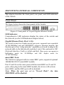
The figure below shows the front panels of the Switch.
Figure 4. Front panel of 24-port Gigabit Ethernet Switch
LED Indicator:
Comprehensive LED indicators display the status of the switch and
the network (see the LED Indicators chapter below).
Gigabit Ethernet Ports (Port 1~24):
The Switch twenty-four Gigabit twisted pair ports, supported auto negotiable
10/100/1000Mbps and auto MDI/MDIX crossover detection function, this
function gives true “plug and play” capability, just need to plug-in the
network cable to the hub directly and don’t care if the end node is NIC
(Network Interface Card) or switch and hub. These ports can operate in
half-duplex mode
10/100/1000Mbps.
for
10/100Mbps
and
full-
duplex
mode
for
mini-GBIC Ports
The Switch is equipped with two mini-GBIC ports, supported optional
1000BASE-SX/LX mini-GBIC module.
Port 23 and 24 are the same ports with the mini-GBIC no.23 and 24
ports, when plug in the mini-GBIC module, the device will activate
mini-GBIC, and the RJ45 port will be disabled.
Note: When the port was set to “Forced Mode”, the Auto
MDI/MDIX will be disabled.
13