1
Bimpliuitq
0 P E RATO
Jn
UAL
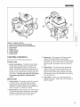
rrne ia Frame
Snowthrowers
intermediate
IVlfg. No.
1695302
1695311
1695410
1695313
1695314
1695411
Frame Snowthrowers
Description
SM11924E B&S 24
SM11924EX B&S 24 (CE)
SM11924RX MS B&S 24 (CE)
SNP 1924E B&S 24
SNP 11924EX B&S 24 (CE)
SNP 1924RX MS B&S 24 (CE)
CAUTION:
Readand
followall instructions.
ManualPartNo. 1734501
Revision 01
Rev. Date 08/2007
TP 100-4609-01-1W-SN
SAVETHESEiNSTRUCTiONS
READTHEMANUAL
Theoperator'smanualcontains
importantsafetyinformation
youneedtobe awareof BEFORE
youoperateyourunitas
well asDURINGoperation.
Safe operating techniques, an explanation of the product's features and controls, and maintenance
information is included to help you get the most out of your equipment investment,
Failure to obey the safety rules could result in loss of control of the unit, severe personal injury or death to
you, or bystanders, or damage to property or equipment,
Safety icons
The alert symbol ,i_ is used to identify safety information
about hazards that can result in personal injury. A signal
word (DANGER,WARNING,or CAUTION)is used with the
alert symbol to indicate the likelihood and the potential
severity of the injury. In addition, a hazardicon may be used
to represent the type of hazard. An explanation of hazard
levels and icons are as follows:
DANGER
This indicates a hazardwhich, if not avoided, will resultin
serious injuryor death.
WARNING
You must read, understand and comply with all
safety and operating instructions in this
manual before attempting to set-up and
operate your snowthrower.
Failure to comply with all safety and operating
instructions can result in loss of machine
control, serious personal injury to you and/or
bystanders, and risk of equipment and
property damage. The triangle in the text
signifies important cautions or warnings which
must be followed.
WARNING
This indicates a hazardwhich, if not avoided, could result in
serious injuryor death.
CAUTION
This indicates a hazardwhich, if not avoided, might result in
minor or moderate injury.
SAFETY
DECALS
This unit has been designed and manufactured to
provide you with the safety and reliability you would
expect from an industry leader in outdoor power
equipment manufacturing.
WARNING
Engine exhaust from this product contains
chemicals known, in certain quantities, to
cause cancer, birth defects, or other
reproductive
harm.
These labels are easily applied and will act as a
constant visual reminder to you, and others who may
use the equipment, to follow the safety instructions
necessary for safe, effective operation.
Although reading this manual and the safety
instructions it contains will provide you with the
necessary basic knowledge to operate this equipment
safely and effectively, we have placed several safety
labels on the unit to remind you of this important
information while you are operating your unit.
All DANGER, WARNING, CAUTION and
instructional messages on your product should be
carefully read and obeyed, Personal bodily injury can
result when these instructions are not followed, The
information is for your safety and it is important,
If any decals are lost or damaged, replace them at
once. See your local dealer for replacements.
Read and obey a// operation
and warning
decals.
Table of Contents
Co
d)
Operator Safety ..........................................
Readthe Manual .............................................
Safety Rules and information ....................................
Safety Decals................................................
Safety icons ................................................
identification Numbers........................................
2
2
4
8
10
11
Features & Controls ......................................
Control Locations............................................
12
12
Operation .............................................
General Operation ...........................................
Starting Controls ............................................
Starting the Engine...........................................
Stopping the Engine..........................................
Operating the Snowthrower ....................................
Ground Speed Selector .......................................
Engine Speed...............................................
Deflector ..................................................
Scraper Bar & Skid Shoes .....................................
Traction Drive Lock ..........................................
Clearing a Clogged Discharge Chute .............................
After EachUse ..............................................
Storage ...................................................
14
14
15
16
17
17
17
17
18
18
18
19
19
19
Maintenance ...........................................
Maintenance Schedule........................................
CheckingTire Pressure .......................................
Auger Gear Case Lubrication ...................................
Lubrication .................................................
20
21
21
21
21
Regular Maintenance.........................................
22
"1"1
CP
r-
Cb
©
©
60
O
-C_
d)
©
d_
O
d)
f---.,
-q
Troubleshooting, Adjustment, and Service .......................
Troubleshooting
.............................................
24
24
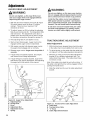
Adjustments ............................................
Auger Drive Adjustment .......................................
Traction Drive CableAdjustment ................................
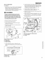
Run-in Adjustment ...........................................
Belt Adjustment .............................................
Shear Pin Replacement .......................................
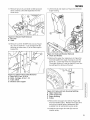
Belt GuideAdjustment ........................................
Belt Replacement............................................
26
26
26
27
28
29
29
30
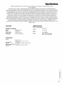
Specifications ..........................................
35
Parts and Accessories ...............................
Parts .......................................................
Maintenance items.............................................
Technical Manuals .............................................
©
C
CT
©
©
¢O
r-
B
d)
Co
BackCover
d_
<
O
d)
Co
-O
d)
_o
O
m.
©
3
ill
g
O9
Congratulations on purchasing a superior-quality piece of
lawn and garden equipment. Our products are designed
and manufactured to meet or exceed all industry
standards for safety.
Power equipment is only as safe as the operator. If it is
misused, or not properly maintained, it can be dangerous!
Remember, you are responsible for your safety and that of
those around you.
Use common sense, and think through what you are
doing. If you are not sure that the task you are about to
perform can be safely done with the equipment you have
chosen, ask a professional: contact your local authorized
dealer.
The operator's manual contains important safety
information you need to be aware of BEFORE you operate
your unit as well as DURING operation.
Safe operating techniques, an explanation of the product's
features and controls, and maintenance information is
included to help you get the most out of your equipment
investment.
Be sure to completely read the Safety Rules and
Information found on the following pages. Also completely
read the Operation section.
DII
Tragic accidents can occur with children. Do not allow
them anywhere near the area of operation. Children
are often attracted to the unit and snowthrowing
activity. Never assume that children will remain where
you last saw them. If there is a risk that children may
enter the area where you are operating the unit, have
4
another responsible adult watch them.
DO NOT ALLOW CHILDREN TO OPERATE THIS
UNIT! This encourages them to come near the unit in
the future while it is running, and they could be
seriously hurt. They may then approach the unit when
you are not expecting it, and you may run over them.
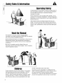
SaletyRulesandInfomatm
N0vJng
Co
This equipment has many moving parts that can injure you or someone else.
However, if you are standing in the operator's position, and follow all the rubs
in this book, the unit is safe to operate.
,--t-
The auger and impeller have spinning parts that can amputate hands and feet.
Do not allow anyone near the equipment while it is running! DO NOT clear the
discharge chute by hand. If the chute becomes plugged, stop the engine, wait
for all moving parts to stop, and clear the blockage with a clean-out tool or
piece of wood.
To help you, the operator, use this equipment safely, it is equipped with an
operator-present safety system. Do NOT attempt to alter or bypass the
system. See your dealer immediately if the system does not pass all the
safety interlock system tests found in this manual.
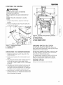
Thrown
ects
This unit has a spinning auger and impeller.
They pick up and throw snow and ice. Thrown
debris could seriously injure a bystander.
ALWAYS direct the discharge chute away from
bystanders and property that could be damaged
by frying debris. Be sure to clean up the area to
be cleared BEFORE you start.
Do not allow anyone in the area while the unit is
running! If someone does enter the area, shut
the unit off immediately until they leave.
Gasoline is extremely flammable. Its vapors are also
extremely flammable and can travel to distant ignition
sources. Gasoline must only be used as a fuel, not as
a solvent or cleaner. It should never be stored any
place where its vapors can build up or travel to an
ignition source like a pilot light. Fuel belongs in an
approved, plastic, sealed gas can, or in the
snowthrower fuel tank with the cap securely closed.
Spilled fuel needs to be cleaned up immediately.
Proper maintenance is critical to the safety and
performance of your unit. Be sure to perform the
maintenance procedures listed in this manual,
especially periodically testing the safety system.
5
SafetyRules& Informtm
This machine is capable to amputating hands and feet and throwing objects. Read these safety rules
and follow them closely. Failure to obey these rules could result in loss of control of unit, severe
personal injury or death to you, or bystanders, or damage to property or equipment. _The
triangle in
text signifies important cautions or warnings which must be followed.
TRAINING
1. Read, understand, and follow all instructions on the
machine and in the manuals before operating this
unit. Be thoroughly familiar with the controls and
the proper use of the equipment. Know how to
stop the unit and disengage the controls quickly.
2. Never allow children to operate the equipment.
Never allow adults to operate the equipment
without proper instruction.
3. Keep the area of operation clear of all persons,
particularly small children and pets.
4. Exercise caution to avoid slipping or falling
especially when operating in reverse.
_j
PREPARATION
1. Thoroughly inspect the area where the equipment
is to be used and remove all doormat, sleds,
boards, wires, and other foreign objects.
2. Disengage all clutches and shift into neutral before
starting engine (motor).
3. Do not operate the equipment without wearing
adequate winter outer garments. Wear footwear
that will improve footing on slippery surfaces.
Avoid loose fitting clothing that can get caught in
moving parts.
4. Handle fuel with care; it is highly flammable.
(a) Use an approved fuel container.
(b) Never add fuel to a running engine or hot
engine.
(c) Fill fuel tank outdoors with extreme care. Never
fill fuel tank indoors. Replace fuel cap securely
and wipe up spilled fuel.
(d) Never fill containers inside a vehicle or on a
truck or trailer bed with a plastic liner. Always
place containers on the ground, away from your
vehicle, before filling.
(e) When practical, remove gas-powered
equipment from the truck or trailer and refuel it on
the ground. If this is not possible, then refuel such
on a trailer with a portable container, rather than
from a gasoline dispenser nozzle.
(f) Keep nozzle in contact with the rim of the fuel
tank or container opening at all times, until
refueling is complete. Do not use a nozzle lockopen device.
(g) Replace gasoline cap securely and wipe up
spilled fuel.
(h) If fuel is spilled on clothing, change clothing
immediately.
5. Use extension cords and receptacles as specified
by the manufacturer for all units with electric drive
motors or electric starting motors.
6. Adjust the collector housing height to clear gravel
or crushed rock surfaces.
7. Never attempt to make any adjustments while the
engine (motor)is running (except when specifically
recommended by the manufacturer).
8. Let engine (motor) and machine adjust to outdoor
temperatures before starting to clear snow.
6
9. Always wear safety glasses or eye shields during
operation or while performing an adjustment or
repair to protect eye from foreign objects that may
be thrown from the machine.
OPERATION
1. Do not put hands or feet near or under rotating
parts. Keep clear of the discharge opening at all
times.
2. Exercise extreme caution when operating on or
crossing gravel drives, walks, or roads. Stay alert
for hidden hazards or traffic.
3. After striking a foreign object, stop the engine
(motor), remove the wire from the spark plug,
disconnect the cord on electric motors, thoroughly
inspect the snowthrower for any damage, and
repair the damage before restarting and operating
the snowthrower.
4. If the unit should start to vibrate abnormally, stop
the engine (motor) and check immediately for the
cause. Vibration is generally a warning of trouble.
5. Stop the engine (motor) whenever you leave the
operating position, before unclogging the
collector/impeller housing or discharge guide, and
when making any repairs, adjustments, or
inspections.
6. When cleaning, repairing, or inspecting make
certain the collector/impeller and all moving parts
have stopped. Disconnect the spark plug wire and
keep the wire away from the plug to prevent
accidental starting.
7. Do not run the engine indoors except for starting
the engine or for transporting the snowthrower in or
out of the building. Open the outside doors;
exhaust fumes are dangerous.
8. Exercise extreme caution when operating on
slopes.
Do not attempt to clear steep slopes.
9. Never operate the snowthrower without proper
guards plates, or other safety protective devices in
place and working.
10. Never direct the discharge toward people or areas
where property damage can occur. Keep children
and others away.
11. Do not overload the machine capacity by
attempting to clear snow at too fast a rate.
12. Never operate the machine at high transport
speeds on slippery surfaces. Look behind and use
care when operating in reverse.
13. Disengage power to the collector/impeller when
snowthrower is transported or not in use.
14. Use only attachments and accessories approved
by the manufacturer of the snowthrower (such as
wheel weights, counterweights, or cabs).
15. Never operate the snowthrower without good
visibility or light. Always be sure of your footing,
and keep a firm hold on the handles. Walk, never
run.
16. Never touch a hot engine or muffler.
17. Never operate the snowthrower near glass
enclosures, automobiles, window wells, drop-offs,
and the like without proper adjustment of the
SafetyRulesaridIflfematm
discharge angle.
18. Never direct discharge at bystanders or allow
anyone in front of the unit.
19. Never leave a running unit unattended. Always
disengage the auger and traction controls, stop
engine, and remove keys.
20. Do not operate the unit while under the influence of
alcohol or drugs.
21. Keep in mind the operator is responsible for
accidents occurring to other people or property.
22. Data indicates that operators, age 60 years and
above, are involved in a large percentage of power
equipment-related injuries. These operators
should evaluate their ability to operate the unit
safely enough to protect themselves and others
from injury.
23. DO NOT wear long scarves or loose clothing that
could become entangled in moving parts.
24. Snow can hide obstacles. Make sure to remove all
obstacles from the area to be cleared.
CHILDREN
Tragic accidents can occur if the operator is not alert to
the presence of children. Children are often attracted to
the unit and the operating activity. Never assume that
children will remain where you last saw them.
1. Keep children out of the area and under the
watchful care of another responsible adult.
2. Be alert and turn unit off if children enter the area.
3. Never allow children to operate the unit.
4. Use extra care when approaching blind corners,
shrubs, trees, or other objects that may obscure
vision.
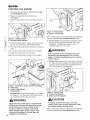
CLEARING
CHUTE
A CLOGGED
DISCHARGE
Hand contact with the rotating impeller inside the
discharge chute is the most common cause of injury
associated with snowthrowers. Never use your hand
to clean out the discharge chute.
To clear the chute:
1. SHUT OFF THE ENGINE.
2. Wait 10 seconds to be sure the impeller blades
have stopped rotating.
3. Always use a clean out tool, not your hands.
SERVICE,
MAINTENANCE,
AND STORAGE
until fuel vapors have dissipated.
7. Always observe safe refueling and fuel handling
practices when refueling the unit after
transportation or storage.
8.Always follow the engine manual instructions for
storage preparations before storing the unit for
both short and long term periods.
9. Always follow the engine manual instructions for
proper start-up procedures when returning the unit
to service.
10. Maintain or replace safety and instruction labels as
necessary.
11. Keep nuts and bolts tight and keep equipment in
good condition.
12. Never tamper with safety devices. Check their
proper operation regularly and make necessary
repairs if they are not functioning properly.
13. Components are subject to wear, damage, and
deterioration. Frequently check components and
replace with manufacturer's recommended parts,
when necessary.
14. Check control operation frequently. Adjust and
service as required.
15. Use only factory authorized replacement parts
when making repairs.
16. Always comply with factory specifications on all
settings and adjustments.
17. Only authorized service locations should be utilized
for major service and repair requirements.
18. Never attempt to make major repairs on this unit
unless you have been properly trained. Improper
service procedures can result in hazardous
operation, equipment damage and voiding of
manufacturer's warranty.
19. Check shear bolts and other bolts at frequent
intervals for proper tightness to be sure the
equipment is in safe working condition.
Co
,--.4-
EMISSIONS
1. Engine exhaust from this product contains
chemicals known, in certain quantities, to cause
cancer, birth defects, or other reproductive harm.
2. If available, look for the relevant Emissions
Durability Period and Air Index information on the
engine emissions label.
IGNITION
SYSTEM
1. This spark ignition system complies with Canadian
ICES-002.
1. Check shear bolts and other bolts at frequent
intervals for proper tightness to be sure the
equipment is in safe working condition.
2. Never store the machine with fuel in the fuel tank
inside a building where ignition sources are present
such as hot water and spacer heaters, or clothes
dryers. Allow the engine to cool before storing in
any enclosure.
3. Always refer to the operator's manual for important
details if the snowthrower is to be stored for an
extended period.
4. Maintain or replace safety and instruction labels as
necessary.
5. Run the machine a few minutes after throwing
snow to prevent freeze-up of the collector/impeller.
6. If fuel is spilled, do not attempt to start the engine
but move the machine away from the area of
spillage and avoid creating any source of ignition
7
instructions are not followed. The information is for
your safety and it is important.
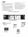
DECALS
>,
This unit has been designed and manufactured to
provide you with the safety and reliability you would
expect from an industry leader in outdoor power
equipment.
O9
The safety decals below are on your unit.
If any of these decals are lost or damaged, replace
them at once. See your local dealer for replacements.
Although reading this manual and safety instructions it
contains will provide you with the necessary basic
knowledge to operate this equipment safely and
effectively, we have placed several safety labels on
the unit to remind you of this important information
while you are operating your unit.
_j
These labels are easily applied and will act as a
constant visual reminder to you, and others who may
use the equipment, to follow the safety instructions
necessary for safe, effective, operation.
NOTE. Engine operation and safety decals are
supplied by the engine manufacturer.
All WARNING, CAUTION, and instructional messages
on your unit should be carefully read and obeyed.
Personal bodily injury can result when these
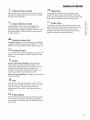
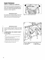
NORTH
AMERICAN
MODEL
DECALS
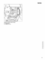
• Keep area of operation clearof
all persons, especially children.
Carbonmonoxide hazard
_
#
Thisengineemits poisonouscarbonmonoxidegas
- Avoidhlha_ingexhaustfumes
- 0n_yoperateou_doms
• Keepmachine maintained
and guards in place,
• Neverallow children to
operate the snow';hrower.
Gasolineisflm_/mablo.
Fire
- klbw hazard
engineto coo_for at _east3 minu_esbefore
refuding
• Stop engine anddisconnect
spark plug wire before
servicing the unit•
• Always direct discharge chuteso
as to avoid iniury to persons or
damage to property.
Part No. 1734499 - DASH SMI/SNAPPER
Main Dash Decal, North American
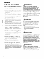
,_
•
The
•
lubrication
poir0s
s]mW4Hlere
mtlSt
be lubricated
.__xb
,t_"
be_o,_
u,ingthe..,it
af_,S_o,age,
_aiiLi,_
to iub,i_at_
w4th_0weight
oil_,_r_'
101,ours
ofope_t_on,
and
Part No. 1733526
Lubrication Decal
Use clean-out
_j
I'_
pKeephandsfeetandd0thing I
]...........................
!:!:_!!
:1!'1:!_!_!::_:':