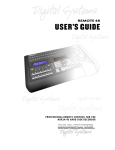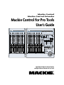
1
Mackie Control
Mackie Control Extender
Mackie Control for Pro Tools
User’s Guide
CONTROL EXTENDER
CONTROL
MACKIE FADER PACK VERSION 1.0
HOURS
MINUTES
SECONDS
FRAMES
BARS
BEATS
SUB DIVISION
TICKS
RUDE
SMPTE
MACKIE FADER PACK VERSION 2.0
BEATS
SOLO
ASSIGNMENT
DISPLAY
METERS
ASSIGNMENT
VIEW
I/O
PAN
SENDS
PLUG-IN
NAME
METERS
REC
REC
REC
REC
REC
REC
REC
REC
REC
REC
REC
REC
REC
REC
REC
REC
SIGNAL
SIGNAL
SIGNAL
SIGNAL
SIGNAL
SIGNAL
SIGNAL
SIGNAL
SIGNAL
SIGNAL
SIGNAL
SIGNAL
SIGNAL
SIGNAL
SIGNAL
SIGNAL
SOLO
SOLO
SOLO
SOLO
SOLO
SOLO
SOLO
SOLO
SOLO
SOLO
SOLO
SOLO
SOLO
SOLO
SOLO
SOLO
MUTE
MUTE
MUTE
MUTE
MUTE
MUTE
MUTE
MUTE
MUTE
MUTE
MUTE
MUTE
MUTE
MUTE
MUTE
MUTE
PAN
ASSIGN
PLUG-INS
SEND
EQ
INPUT
DYN
OUTPUT
F1
EIGHT CHANNEL MASTER CONTROL
SMPTE
CLEAR
PEAKS
BEATS
VALUE
EDIT
MIX
F2
TRANSPORT
F3
MEM LOC
F4
F5
ALT VIEW
FADER BANKS
F6
CUT
PLUG-IN
ASSIGN
SEPERATE
F7
COMPARE
PASTE
F8
BYPASS
BANK
BANK
READ
F9
WRITE
F10
SEND A
SEND B
TOUCH
LATCH
F11
F12
SEND C
SEND D
TRIM
F13
SEND E
OFF
F14
SHIFT
AUTO
F15
SND MUTE
DEFAULT
F16
CHANNEL
CHANNEL
SELECT
SELECT
SELECT
SELECT
SELECT
SELECT
SELECT
SELECT
SELECT
SELECT
SELECT
SELECT
SELECT
SELECT
SELECT
SELECT
1
2
3
4
5
6
7
8
1
2
3
4
5
6
7
8
MODIFIERS
MODIFIERS
FLIP
V-SEL
10
dB
+
10
dB
+
10
dB
+
10
dB
+
10
dB
+
10
dB
+
10
dB
+
10
+
dB
dB
dB
dB
dB
dB
dB
dB
10
10
10
10
10
10
10
10
10
+
+
+
+
+
+
+
CTRL/CLUTCH
CONTROL
5
5
5
5
5
5
5
5
5
5
5
5
5
5
5
5
5
U
U
U
U
U
U
U
U
U
U
U
U
U
U
U
U
U
5
5
10
5
10
0
5
10
0
5
10
0
5
10
0
5
10
0
5
10
0
5
10
0
5
10
0
5
10
0
5
10
0
5
10
0
5
10
0
5
10
0
5
10
0
5
10
0
20
20
20
20
20
20
20
20
20
20
20
20
20
20
20
20
30
30
30
30
30
30
30
30
30
30
30
30
30
30
30
30
40
40
40
40
40
40
40
40
40
40
40
40
40
40
40
40
50
50
50
50
50
50
50
50
50
50
50
50
50
50
50
50
60
60
60
60
60
60
60
60
60
60
60
60
60
60
60
60
–
–
–
–
–
–
–
–
–
–
–
–
–
IN
FRM
RTZ
/ALT
ALT
OUT
FRM
END
REWIND
30
–
FADER
ON
MUTE
REC/RDY
PLUG-IN
UNDO
SAVE
CANCEL
UNDO
ENTER
PAN
SNAPSHOT
SEND
TOUCH
SEND
MUTE
REDO
ESC/CANCEL
MARKER
ENTER
MIXER
ONLINE
PI
POST
TRANSPORT
PO
FUNCTION
CUE
MGR
HOME
SUSPEND
END
LOOP
LOOP
PRE
10
0
20
–
OPTION/ALL
OPTION
MASTER
dB
+
FUNCTIONS
UTILITIES
EDIT
INSERT
SHIFT/ADD
SHIFT
dB
AUTOMATION
AUTO ENABLE
FAST FWD
STOP
PLAY
RECORD
40
50
60
SCRUB
–
ZOOM
Eight Channel Master Control Surface
and Eight Channel Extender for Pro Tools
Mackie Control
CAUTION
AVIS
RISK OF ELECTRIC SHOCK
DO NOT OPEN
RISQUE DE CHOC ELECTRIQUE
NE PAS OUVRIR
CAUTION: TO REDUCE THE RISK OF ELECTRIC SHOCK
DO NOT REMOVE COVER (OR BACK)
NO USER-SERVICEABLE PARTS INSIDE
REFER SERVICING TO QUALIFIED PERSONNEL
ATTENTION: POUR EVITER LES RISQUES DE CHOC
ELECTRIQUE, NE PAS ENLEVER LE COUVERCLE. AUCUN
ENTRETIEN DE PIECES INTERIEURES PAR L’USAGER. CONFIER
L’ENTRETIEN AU PERSONNEL QUALIFIE.
AVIS: POUR EVITER LES RISQUES D’INCENDIE OU
D’ELECTROCUTION, N’EXPOSEZ PAS CET ARTICLE
A LA PLUIE OU A L’HUMIDITE
The lightning flash with arrowhead symbol within an equilateral
triangle is intended to alert the user to the presence of uninsulated
"dangerous voltage" within the product’s enclosure, that may be
of sufficient magnitude to constitute a risk of electric shock to persons.
Le symbole clair avec point de fl che l’int rieur d’un triangle
quilat ral est utilis pour alerter l’utilisateur de la pr sence
l’int rieur du coffret de "voltage dangereux" non isol d’ampleur
suffisante pour constituer un risque d’ l ctrocution.
The exclamation point within an equilateral triangle is intended to
alert the user of the presence of important operating and maintenance
(servicing) instructions in the literature accompanying the appliance.
Le point d’exclamation l’int rieur d’un triangle quilat ral est
employ pour alerter les utilisateurs de la pr sence d’instructions
importantes pour le fonctionnement et l’entretien (service) dans le
livret d’instruction accompagnant l’appareil.
Important Safety Instructions
1. Read instuctions — Read, understand and follow all safety and
operating instructions before using this Mackie product.
2. Retain Instructions — Keep these safety and operating
instructions for future reference.
D. The unit does not appear to operate normally or exhibits a
marked change in performance; or
E. The unit has been dropped, or its chassis damaged.
12. Servicing — Do not attempt to service this Mackie product. All
servicing should be referred to the Mackie Service Department.
13. Lightning — Unplug the product during lightning storms or
when unused for long periods of time. Note that this Mackie
product is not completely disconnected from the AC mains
service when the power switch is in the OFF position.
14. Grounding and Polarization — To prevent electric shock, do not
use the polarized plug with an extension cord, receptacle or
other outlet unless the blades can be fully inserted to prevent
blade exposure. Do not defeat the grounding by plugging into an
ungrounded receptacle or ground lift adapter.
This apparatus does not exceed the Class A/Class B (whichever is
applicable) limits for radio noise emissions from digital apparatus as
set out in the radio interference regulations of the Canadian
Department of Communications.
ATTENTION — Le présent appareil numérique n’émet pas de bruits
radioélectriques dépassant las limites applicables aux appareils
numériques de class A/de class B (selon le cas) prescrites dans le
réglement sur le brouillage radioélectrique édicté par les ministere
des communications du Canada.
3. Heed Warnings — Follow all warnings on this Mackie product
and in these operating instructions.
FCC Information
4. Water and Moisture — Do not use this Mackie product near
water – for example, near a bathtub, kitchen sink, garden hose,
incontinent poodle, sweaty drummer, etc. – or when condensation has formed on the unit.
NOTE: This equipment has been tested and found to comply
with the limits for Class B digital devices, pursuant to Part 15 of
the FCC Rules. These limits are designed to provide reasonable
protection against harmful interference when the equipment is
operated in a commercial installation. This equipment generates,
uses, and can radiate radio frequency energy and, if not installed
and used in accordance with the instruction manual, may cause
harmful interference to radio communications. Operation of this
equipment in a residential area is likely to cause harmful
interference in which case the user will be required to correct
the interference at his own expense.
5. Cleaning — Clean only with a dry cloth.
6. Heat and Ventilation — Locate this Mackie product away from
heat sources such as radiators, campfires, compost pits, heliarc
welders, magma flows, etc. Do not block the ventilation
openings or install in spaces that prevent adequate air circulation
to the unit.
7. Power Sources — Connect this Mackie product only to a power
source of the type described in these operating instructions or as
marked on the product.
8. Power Cord Protection — Route power supply cords so that they
are not likely to be walked upon, tripped over, or abraded by
items placed upon or against them. Pay particular attention to
cords at plugs, convenience receptacles, and the point where
they exit the product.
9. Object and Liquid Entry — Do not drop objects or spill liquids
into this Mackie product. Clean only with a damp cloth; do not
clean with liquid or aerosol cleaners.
10. Attachments — Use this Mackie product with only the
accessories specified in this manual.
11. Damage Requiring Service — This Mackie product should be
serviced only by qualified service personnel when:
This product has been tested and complies
with the following standards and directives
as set forth by the European Union:
* EN 55022 Radiated and Conducted Emissions
* EN 55024 Electromagnetic Immunity
* EN 61000-4-2 Electrostatic Discharge Immunity
* EN 61000-4-3 RF Electromagnetic Fields Immunity
* EN 61000-4-4 Electrical Fast Transient/Burst Immunity
* EN 60950/IEC 950 Electrical Safety Requirements
WARNING — To reduce the risk of fire or electric shock, do
not expose this appliance to rain or moisture.
A. The power supply cord or the plug has been damaged; or
B. Objects have fallen onto, or liquid has spilled into the unit; or
C. The unit has been exposed to rain or water; or
2
Mackie Control HUI Mode
Part No. SW0063 Rev. A 04/03
© 2003 Mackie Designs Inc. All Rights Reserved.
User’s Guide
Note: If you purchased a Mackie Control on or after March 1, 2003 that has not yet been upgraded,
you can receive a free upgrade kit by going to our website at http://www.mackie.com/products/
mackiecontrol/upgrade_kit.html (or you can call Mackie Tech Support at 1-800-258-6883). If you prefer,
you can send the unit to the Mackie Woodinville Service Center for the upgrade (a labor charge will apply).
You will need to provide a copy of your sales receipt with the purchase date for the free upgrade kit.
If you purchased a Mackie Control before March 1, 2003, you can either request an upgrade kit from
Mackie at a nominal cost, or send the unit to the Mackie Woodinville Service Center to have the upgrade
performed for the cost of the upgrade kit and a labor charge.
Introduction
Thank you for choosing Mackie Designs for your
Pro Tools control solution. Mackie Control and
Mackie Control Extender provide the familiar feel of
analog-style mixing to your Digital Audio
Workstation (DAW) environment. It will improve
your efficiency and unleash your creativity so you
can focus on the music, and not the interface.
Here are a few tips to get you started using
Mackie Control with Pro Tools:
•
Make sure HUI Mode is selected (see
“Selecting HUI Mode” on page 7).
•
Make sure the overlay (included with the
upgrade kit or with the Version 2 Mackie
Control) is placed over the right-hand side of
the Mackie Control.
•
When using a Mackie Control Extender with
Mackie Control, be sure to assign the Mackie
Control to Peripheral Slot 1 in Pro Tools. This
will give you the ability to edit plug-ins by
banking channels over to the eight channel
strips on the Mackie Control.
•
The Mackie Control Extender only supports
the Pan function with its V-Pots. Plug-in
parameters can only be edited on the Mackie
Control (via Peripheral Slot 1).
•
Place the Mackie Control to the left of the
Extender(s), so the channels are correctly
oriented with the channels on-screen in Pro
Tools, starting with channel 1 on the Mackie
Control.
•
The Master Fader on the Mackie Control is
not supported in Pro Tools, so it is disabled.
•
Mackie Control will work with Pro Tools v4.1
and higher, on either the PC or Macintosh
platforms.
•
Refer to the HUI section in Digidesign’s
“MIDI Control Surfaces Guide” for more
information on setting up and using Mackie
Control HUI mode with Pro Tools, available on
their website at:
How HUI Mode Works
In order to best understand how to use the
Mackie Control HUI mode with Pro Tools, it is
helpful to know exactly how Pro Tools and HUI
mode work together. The Mackie Control emulates
the MIDI protocol of the original Mackie HUI
(Human User Interface), acting as a hardware
“shell” of the mixer in Pro Tools by becoming the
physical embodiment of the faders, knobs, and
buttons found in the software. This effectively
eliminates the ordeal of having to mix using a
computer mouse, allowing you to work faster and
concentrate more on the mix than on the technology.
The audio processing in the Pro Tools mixer, however,
is always performed by the mixing engine in the Pro
Tools software/hardware (for TDM/HD systems).
In order to stay in perfect synchronization with
the software, Mackie Control receives information
from Pro Tools telling it which lights should be lit,
what text to display on the LCD, and where the
faders should be at a given time. Likewise, Mackie
Control relays information to Pro Tools regarding
which buttons are being pressed, the direction that
knobs are being turned, etc.
This is all done via the MIDI connection using a
proprietary MIDI protocol, meaning that the Mackie
Control will always reflect the current state of the
Pro Tools mixing engine. It also means that any
feature additions, new plug-ins, or changes to the
Pro Tools software will be reflected in the Mackie
Control without the need for any software updates to
the control surface. All of this adds up to one thing
— the Mackie Control HUI Mode works as a seamless
extension of the Pro Tools DAW environment,
enabling you to work faster and easier, and truly get
the most out of your Pro Tools workstation.
http://www.digidesign.com
Custom lexan overlays are available for other
supported DAWs (see the Overlay Request Card
included in the box). These overlays fit over the
right-hand side of the control surface and correctly
label the buttons for the functionality supported by
the DAW you are using.
User’s Guide
3
Mackie Control
Connection and Setup
Set Up OMS
Connecting a single Mackie Control:
• Connect the Mackie Control to your MIDI
interface. The MIDI Output of your interface
should connect to the MIDI Input of the
Mackie Control. Likewise, the MIDI output of
the Mackie Control should be connected to a
corresponding MIDI Input of your interface.
•
(Macintosh OS 9.x or lower only)
Mac users will need to set up a device for their
Mackie Control under OMS.
1. From Pro Tools, open the OMS Studio Setup
so you can configure your MIDI devices.
Connect one end of the external power supply
to the Mackie Control, and the other end to an
AC power source (between 90 and 264 VAC,
50–60 Hz).
Connecting a Mackie Control Extender:
• Connect the Mackie Control to the first
available port of your MIDI interface using
the steps described above.
•
Connect the Mackie Control Extender to the
next available port on the MIDI interface,
again following the steps described above for
the Mackie Control.
2. From the File menu, select New Studio Setup.
(If you already have a Setup you would like to
edit, skip to step 7.)
Connecting multiple Mackie Controls and Mackie
Control Extenders:
When connecting multiple Mackie Controls/
Extenders, each unit must be connected to its own
MIDI port on the computer’s MIDI interface; i.e., the
first Mackie Control would connect to Port 1 Input/
Output of the MIDI interface, the second Mackie
Control/Extender would connect to Port 2 Input/
Output, and so forth.
CONTROL EXTENDER
THE FOLLOWING ARE TRADEMARKS OR REGISTERED TRADEMARKS OF MACKIE DESIGNS INC "MACKIE" AND THE "RUNNING MAN" FIGURE
SERIAL NUMBER
Mackie Control
Mackie Control Extender
Mackie Control Extender
CONTROL EXTENDER
THE FOLLOWING ARE TRADEMARKS OR REGISTERED TRADEMARKS OF MACKIE DESIGNS INC "MACKIE" AND THE "RUNNING MAN" FIGURE
MANUFACTURING DATE
IN
LISTED INFORMATION
TECHNOLOGY EQUIPMENT
59BJ
MIDI
OUT
EXTERNAL
POWER
–
POWER
SERIAL NUMBER
MANUFACTURING DATE
CONTROL EXTENDER
MIDI
OUT
EXTERNAL
POWER
–
POWER
+
MANUFACTURING
DATE
SERIAL
THENUMBER
FOLLOWING ARE TRADEMARKS
OR REGISTERED
TRADEMARKS OF MACKIE DESIGNS INC "MACKIE" AND THE "RUNNING MAN" FIGURE
WARNING:
RISK OF ELECTRIC SHOCK
DO NOT OPEN
REPLACE WITH THE SAME TYPE FUSE AND RATING.
DISCONNECT SUPPLY CORD BEFORE CHANGING FUSE
CONCEIVED, DESIGNED, AND MANUFACTURED BY MACKIE DESIGNS INC. • WOODINVILLE • WA • USA • MADE IN USA • FABRIQUE AU USA • COPYRIGHT ©2001
MIDI
IN
MIDI
IN
SERIAL NUMBER
TO REDUCE THE RISK OF FIRE OR ELECTRIC SHOCK, DO NOTLISTED INFORMATION
EXPOSE THIS EQUIPMENT TO RAIN OR MOISTURE. DO NOT REMOVE COVER. TECHNOLOGY EQUIPMENT
NO USER SERVICEABLE PARTS INSIDE. REFER SERVICING TO QUALIFIED PERSONNEL.
59BJ
UTILISE UN FUSIBLE DE RECHANGE DE MÊME TYPE.
DEBRANCHER AVANT DE REMPLACER LE FUSIBLE
MIDI
OUT
Digital Audio Workstation
Multiport
MIDI Interface
4
Computer Serial or
USB Connection
Mackie Control HUI Mode
IN
MIDI
MANUFACTURING DATE
AVIS: RISQUE DE CHOC ELECTRIQUE — NE PAS OUVRIR
OUT
EXTERNAL
POWER
–
POWER
USER SWITCH
EXTERNAL
CONTROL
IN
MIDI
OUT
EXTERNAL
POWER
–
+
POWER
+
LISTED INFORMATION
TECHNOLOGY EQUIPMENT
59BJ
CONCEIVED, DESIGNED, AND MANUFACTURED BY MACKIE DESIGNS INC. • WOODINVILLE • WA • USA • MADE IN USA • FABRIQUE AU USA • COPYRIGHT ©2001
CONCEIVED, DESIGNED, AND MANUFACTURED BY MACKIE DESIGNS INC. • WOODINVILLE • WA • USA • MADE IN USA • FABRIQUE AU USA • COPYRIGHT ©2001
CONCEIVED, DESIGNED, AND MANUFACTURED BY MACKIE DESIGNS INC. • WOODINVILLE • WA • USA • MADE IN USA • FABRIQUE AU USA • COPYRIGHT ©2001
MIDI
OUT
EIGHT CHANNEL MASTER CONTROL
THE FOLLOWING ARE TRADEMARKS OR REGISTERED TRADEMARKS OF MACKIE DESIGNS INC "MACKIE" AND THE "RUNNING MAN" FIGURE
IN
LISTED INFORMATION
TECHNOLOGY EQUIPMENT
59BJ
+
MIDI
IN
MIDI
OUT
6. OMS will now ask you to save your OMS
Studio Setup.
User’s Guide
3. OMS will then ask which ports you would like
to search for MIDI interfaces. If your MIDI
device is USB or PCI you do not need to check
anything.
7. Now that you have configured OMS for your
MIDI interface, you need to setup your MIDI
controller device.
4. Once OMS is done searching for your MIDI
interfaces, you will see the screen below.
Make sure your MIDI device is listed. If it is
not listed, double check its connection and
power and try searching again.
8. The Controller device may appear as a
keyboard with a question mark in it the first
time you run this setup.
5. Click OK. When the search is complete, you
should see a new device listed. Check the
box(es) next to the device’s MIDI ports and
click OK.
9. Double-click the controller device icon (or the
keyboard/question mark icon). This opens the
device configuration window. In this window,
make sure the Manufacturer is Mackie, the
Model is other, and the name is HUI.
10. Repeat step 9 for any Extenders that are in use,
naming them HUI 2, HUI 3, and HUI 4.
11. Once you are done configuring the controller,
click OK. Save the OMS Studio Setup and quit
OMS.
User’s Guide
5
Mackie Control
Configuring Pro Tools
Set Up Input Devices
As stated earlier, Mackie Control HUI mode is a
hardware emulation of the original Mackie HUI, created
by Mackie Designs in 1997. As far as Pro Tools (or any
HUI-compatible software for that matter) is concerned,
the Mackie Control is a HUI, meaning that it is compatible
with every version of Pro Tools from version 4.1 on.
Once Mackie Control has been added as a MIDI
Control Surface in Pro Tools, it is important to make
sure that the MIDI port connected to the Mackie
Control is selected as an input port.
Set Up MIDI Controllers
1. In the Pro Tools main view, click the MIDI
drop-down menu and select Input Devices.
In order for Pro Tools to connect with Mackie
Control, it must first be added as a MIDI Control
Surface in the Pro Tools Peripherals menu.
1. Turn on the POWER switch on the Mackie
Control, and make sure that HUI Mode is
active (see “Selecting HUI Mode” on page 7).
2. Start Pro Tools on your computer.
3. In Pro Tools, click the Setups drop-down
menu and select Peripherals.
4. In the Peripherals dialog box, click the tab
labeled MIDI Controllers.
2. In the Input Devices dialog, be sure that the
box next to the port that the Mackie Control
is connected to is checked (in this example
it’s named HUI), otherwise the Mackie
Control will not be able to communicate
properly with Pro Tools.
5. In the row marked Controller 1, click the box
in the Type column (it should contain the text
“none”), and select HUI from the list.
6. In the same row, click the box in the Send To
column, and select the port that the Mackie
Control is connected to (in this example it’s
named HUI).
3. Check any ports with Mackie Control
Extenders connected as well.
7. Click the box in the Receive From column,
and select the port that the Mackie Control is
connected to (in this example it’s named HUI).
At this point, the Mackie Control should be
connected to and communicating with Pro Tools.
The decimal point LED on the lower-right of the
ASSIGNMENT display above the Master Fader
should be lit. This indicates that Mackie Control is
receiving communication from Pro Tools. If this is
not the case, check your connections and confirm
that the settings described above have all been made.
If Mackie Control is still not communicating with Pro
Tools, refer to the Troubleshooting section on page 7.
8. The #Ch’s should be set to 8 (which is the
only option available).
9. Repeat steps 5-8 on the next row(s) for any
Mackie Control Extenders present.
10. Click OK to exit the window.
6
Mackie Control HUI Mode
4. Click OK to exit the window.
•
Move a fader or knob on your Mackie Control
and the corresponding on-screen control
should move. If it doesn’t, first check all the
MIDI connections. Try using different cables
to make the connections.
•
Move an on-screen fader and see if the
corresponding Mackie Control fader moves. If
it doesn’t, make sure the settings are correct
as described above and in Digidesign’s MIDI
Control Surfaces Guide.
•
Try using a different set of MIDI ports. Repeat
the “Set Up MIDI Controllers” instructions on
page 6 using the new MIDI ports.
•
Check the status of the MIDI interface and
drivers that you are using.
Tutorial: Using HUI Mode
Navigating Around the Mixer
When Mackie Control connects to Pro Tools, the
software assigns eight channels of the Pro Tools
mixer to be represented on the Mackie Control
channel strips. These channels are highlighted in the
Pro Tools mixer window.
Pressing the BANK and BANK buttons [14]
shifts this block of channel strips left or right by 8
channels in the Pro Tools mixer.
Pressing the CHANNEL and CHANNEL buttons [15] does the same, only the Mackie Control
is shifted by a single channel strip. In this manner,
the Mackie Control can access as many tracks as
exist in the Pro Tools mixer.
User’s Guide
Troubleshooting
FADER BANKS
Selecting HUI Mode
•
When the Mackie Control first boots up out of
the box (or after the HUI Mode upgrade), it will
prompt you to select either “Mackie Ctrl” mode
(press Ch. 1 V-Pot) or “HUI” mode (press Ch. 4
V-Pot).
•
Another way to get to the mode select dialog is
to hold down the SELECT buttons on Channels
1 and 2 on boot-up.
•
Once set, the Mackie Control version 2
firmware will “remember” the selected mode
on subsequent boot-ups until the mode select
dialog is changed again as described above.
BANK
BANK
CHANNEL
CHANNEL
FLIP
V-SEL
EDIT
INSERT
Adjusting Channel Pan
Suppose you want to adjust the pan on Track 1
(a mono track) in the Pro Tools mixer. Use the
BANK buttons [14] to highlight tracks 1-8 in the Pro
Tools mixer, and make sure the LED next to the PAN
button [8] is lit (if it isn’t, then just press the PAN
button). Now rotate the V-Pot on channel strip 1 to
pan the signal left or right in the mix.
If Track 1 were a stereo track, you would also
want to pan the right channel of the track. To do
this, press the PAN button a second time. The PAN
LED now flashes, and rotating the V-Pot on Track 1
adjusts the right channel pan in the mix.
ASSIGNMENT
VIEW
I/O
PAN
SENDS
PLUG-IN
PAN
ASSIGN
PLUG-INS
SEND
EQ
INPUT
DYN
OUTPUT
User’s Guide
7
Mackie Control
Assign a Send
Let’s assign a send to Send A on channel 8. Press
ASSIGN [10] and then press SEND [13]. Press and
hold SEND again and press SEND A [28]. Notice the
LCD changes. Turn the V-Pot on channel 8 to choose
the desired Send A destination (e.g., Bus 1) and
press ASSIGN again to apply the change.
DISP
MET
ASSIGNMENT
VIEW
I/O
PAN
SENDS
PLUG-IN
NAME
METERS
VALUE
PAN
ASSIGN
PLUG-INS
SEND
EQ
INPUT
DYN
OUTPUT
F1
EDIT
Notice that the LCD has changed to indicate the
Input assignments on its lower line. The number
before the “/” indicates the ID of the audio interface,
while the number after indicates the channel on that
interface. These numbers will vary depending on the
type of I/O hardware in your Pro Tools system.
••••• ••••• ••••• ••••• ••••• ••••• ••••• •••••
>#1/1 | >#1/2 | >#1/1 | >#1/1 | >#1/1 | >#1/1 | >#1/1 | >#1/1
Rotate the V-Pot on Channel 2 to change the
input assignment, and press the ASSIGN button
again to apply the change. This same procedure can
be used with the OUTPUT button [12] to set a
track’s output destination as well.
Adding a Plug-in to a Track
FADER BANKS
BANK
BANK
READ
F9
SEND A
CHANNEL
CHANNEL
Adjusting Send Level
Adding a plug-in to a track is simple. First use the
BANK buttons [14] to highlight the track in which
you want to insert the plug-in.
Hold down the INSERT button [16] (located just
above the Master Fader), and press the V-Pot on the
channel you want. The LCD changes to show the
Plug-Ins view.
FADER BANKS
If you want to adjust the level of SEND A on
Track 8, first use the BANK buttons [14] to highlight
Tracks 1-8 in the Pro Tools mixer.
Now hold the SEND button [13] down and press
the button marked SEND A [28]. This sets the V-Pot
function to Send A level, and the ASSIGNMENT
display above the master fader indicates “SA”.
DISP
MET
ASSIGNMENT
VIEW
I/O
PAN
SENDS
PLUG-IN
NAME
METERS
VALUE
PAN
ASSIGN
PLUG-INS
SEND
EQ
INPUT
DYN
OUTPUT
F1
EDIT
FADER BANKS
BANK
BANK
BANK
BANK
CHANNEL
CHANNEL
FLIP
V-SEL
EDIT
INSERT
If there are already plug-ins on the channel, the
view may show the parameters of one of the plugins. If this is the case, press V-Pot 5 to change the
view to show the inserts of that channel.
Once you are viewing the four inserts, press the
PLUG-IN ASSIGN button [25] to enter assign mode.
Rotate V-Pots 1 thru 4 to select the plug-in to be
added on each insert, and press the PLUG-IN
ASSIGN when you are finished.
READ
F9
SEND A
DISPLAY
METERS
ASSIGNMENT
VIEW
EIGHT CHANNEL MASTER CONTROL
CHANNEL
CHANNEL
I/O
PAN
Turn the V-Pot on Channel 8 clockwise to
increase the level of Track 8 going to Send A and
counter-clockwise to decrease it.
SENDS
PLUG-IN
NAME
METERS
SMPTE
CLEAR
PEAKS
BEATS
VALUE
PAN
ASSIGN
PLUG-INS
SEND
EQ
INPUT
DYN
OUTPUT
F1
EDIT
F2
MIX
TRANSPORT
F3
MEM LOC
F4
FADER BANKS
Setting a Track’s Input and Output
You can set up a Track’s input in the Pro Tools
mixer from the Mackie Control without ever having
to use your mouse.
For example, to set up Track 2’s input, press the
ASSIGN button [10], then press the INPUT button [11].
ASSIGNMENT
VIEW
8
I/O
PAN
SENDS
PLUG-IN
PAN
ASSIGN
PLUG-INS
SEND
EQ
INPUT
DYN
OUTPUT
Mackie Control HUI Mode
F5
ALT VIEW
F6
CUT
PLUG-IN
ASSIGN
SEPERATE
F7
COMPARE
F8
PASTE
BYPASS
When this is done, you may edit the plug-in you
just added from the LCD by pressing the V-Pot
corresponding to the plug-in’s insert slot.
Writing Automation
One of the key features Mackie Control brings to
a Pro Tools system is the ease in which a mix can be
automated. The easiest way to automate channel
parameters is by using Auto-touch automation. This
automation mode only records automation when a
knob, button, or fader is being touched or moved.
User’s Guide
To set up a channel for auto-touch automation,
hold down the button in the automation section of
Mackie Control labeled TOUCH [30], and press the
V-Pot on the channel you want to automate. This
step can also apply to the other automation modes
(READ, WRITE, LATCH, TRIM, and OFF).
HUI MODE CONTROLS
Channel Strips
[1] REC
FADER BANKS
BANK
BANK
READ
F9
WRITE
SEND A
F10
SEND B
TOUCH
F11
SEND C
LATCH
F12
SEND D
TRIM
F13
SEND E
OFF
F14
SHIFT
AUTO
F15
SND MUTE
F
CHANNEL
CHANNEL
Next, press the button in the AUTO ENABLE
section of Mackie Control corresponding to the type
of parameter you want to automate to enable it for
writing (i.e., if you want to automate faders, make
sure the LED above FADER [40] is lit; likewise for
the other functions).
AUTOMATION
AUTO ENABLE
FU
FADER
ON
MUTE
REC/RDY
PLUG-IN
UNDO
PAN
SNAPSHOT
SEND
TOUCH
SEND
MUTE
REDO
Press PLAY to start Pro Tools’ transport, and
move the fader, V-Pot, knob, or button on the
channel that you want to automate. Press STOP
when you are finished. Rewind and play back the
section you made your changes to and watch the
faders and lights move to the values you just wrote.
For more information about the different automation
modes, consult your Pro Tools manual.
Becoming a Power User
It takes a little time to get to know your way
around ANY new mixer or control surface, so spend
some time mixing with your Mackie Control. You will
undoubtedly find yourself working much faster in
Pro Tools as a result of being free from using a
mouse. You may even find yourself doing things
creatively in your mix that you may not have thought
of previously as a direct result of working with the
Mackie Control.
In addition to the basic controls outlined here,
there are many more shortcuts and combos — too
numerous to cover here — that can be applied from
the Mackie Control to accomplish common tasks in
mixing, grouping, and editing. These can be found in
the HUI section of the Pro Tools MIDI Control
Surfaces Guide available from Digidesign’s website
(www.digidesign.com). Although this document was
originally created as a reference for the original
Mackie HUI, all of the information it contains applies
just as much to HUI mode in Mackie Control, and can
indeed be a powerful guide to unlocking even more
potential of your Mackie Control with Pro Tools.
This button arms or disables the
corresponding Pro Tools track for
recording. The REC LED flashes when
engaged and in Record-Ready mode, and
lights continuously when Pro Tools
begins recording.
REC
[2] SIGNAL LED
SIGNAL
This LED illuminates when a signal is
present in the corresponding Pro Tools
channel.
SOLO
[3] SOLO
Pushing a SOLO button isolates that
channel’s output signal to the mix bus in
Pro Tools. The selected channel’s SOLO
button LED lights and the MUTE buttons
on all the other channels lights.
MUTE
SELECT
[4] MUTE
The MUTE button turns off the
corresponding Pro Tools channel’s output
signal.
1
dB
10
+
[5] SELECT
5
This button selects the corresponding
Pro Tools channel for channel-based
editing or assignment commands.
[6] V-Pot: Press
The V-Pots serve a dual function on the
Mackie Control, acting as a push-button
and a rotary control. When a V-Pot is
pressed, it displays the automation mode
on that channel. Its function can be
modified using the modifier buttons in
the assignment section.
[6] V-Pot: Rotate
The function of the V-Pots is assigned
in the VIEW section. Depending on its
function, the V-Pot is used to adjust a
channel’s pan, send level, or plug-in
parameters.
U
5
10
0
20
30
40
50
60
–
[7] Touch-Sensitive Faders
These 100 mm optical, touch-sensitive, motorized
faders are used to control the channel’s levels, aux
returns, MIDI tracks, and master fader levels. The
eight faders move relative to the activity of the
currently selected bank of on-screen faders. Pro
Tools highlights the eight channels currently being
controlled by the Mackie Control.
Note: The Master Fader on the Mackie Control is
not used in HUI Mode.
User’s Guide
9
Mackie Control
Insert View:
Assignment Buttons
When Insert view is selected in the Plug-In
screen, the LCD displays the available inserts and
the type of plug-in assigned to each insert.
[8] PAN
•
Pressing the PAN button changes the V-Pot
function to Pan.
•
The LED next to the PAN button lights.
•
The ASSIGNMENT display indicates “Pn.”
•
Pressing PAN a second time sets the V-Pots
into Pan Right mode. This mode is used to
pan only the right channel on stereo tracks.
When Pan Right mode is active, the LED
next to the PAN button flashes and the
ASSIGNMENT display indicates “Pr.”
Track 1:
StComprssr Insert 2
•
Rotate Channel 1-4 V-Pots to select a plug-in
for an insert.
•
Press the PLUG-IN ASSIGN button to exit
assign mode and apply the changes.
To select a plug-in for editing:
Press the V-Pot on channel 1-4 corresponding
to the plug-in slot you wish to edit.
•
•
Press V-Pot 5 to enter Parameter View and
edit the plug-in.
[9] PLUG-IN
Parameter View:
•
Pressing the PLUG-IN button changes the
LCD to show the Plug-In view. This view is
used to access the selected channel’s inserts
(for selecting, adding, or removing a plug-in),
or to edit the parameters of a single plug-in.
•
In Plug-in view, there are typically four
parameters or less that are displayed on the
LCD. These four parameters are accessed by
rotating or pressing V-Pots 1-4. V-Pot 5 is
used as a “Page” knob to access additional
parameters or inserts. Rotating it clockwise
scrolls to the next page of plug-in parameters,
while rotating counter-clockwise scrolls to the
previous page.
When Parameter View is active in the Plug-In
screen, the LCD displays the parameters for the
plug-in currently selected for editing. Rotating and
pressing V-Pots 1-4 adjusts the parameters on the
LCD. Rotating V-Pot 5 scrolls through the pages of
parameters available for editing on a particular plug-in.
Inv Off
Type Peak Gain 0.0
Pressing V-Pot 5 toggles between Insert View
(displaying the selected channel’s insert slots)
and Parameter View (displaying the parameters
of the selected plug-in).
•
The V-Pots for channels 6-8 are disabled in
Plug-in view.
•
Press PLUG-IN again to exit Plug-in view.
DISPLAY
METERS
ASSIGNMENT
VIEW
I/O
PAN
SENDS
PLUG-IN
NAME
METERS
PAN
ASSIGN
PLUG-INS
SEND
EQ
INPUT
DYN
OUTPUT
F1
EDIT
10
The assign button is used in conjunction with
the INPUT, OUTPUT, and SEND buttons to
edit the input, output, and send destinations
of channels.
•
Pressing the ASSIGN button enters Assign
Mode. The LED next to the ASSIGN button
flashes and the ASSIGNMENT display above
the master fader shows “As.”
•
The track names on the LCD disappear. At
this point, an I/O routing can be selected to
assign.
To assign the input sources of the current bank of
channels:
• Press the ASSIGN button [10] to enter into
Assign Mode. The ASSIGN LED should be
flashing.
EIGHT CHANNEL MASTER CONTROL
F2
MIX
FADER BANKS
Mackie Control HUI Mode
TRANSPORT
F3
MEM LOC
F4
F5
ALT VIEW
Q
•
SMPTE
CLEAR
PEAKS
BEATS
VALUE
Freq 1.00k
[10] ASSIGN
In addition, the CUT [25], SEPERATE [26],
and PASTE [27] buttons change their function
to PLUG-IN ASSIGN, COMPARE, and BYPASS
in Plug-in view mode, as indicated on the Pro
Tools HUI overlay.
•
Insert 4
To add, change, or remove the plug-in on an insert slot:
Press the PLUG-IN ASSIGN button [25] to
enter assign mode.
•
Note: The PAN control doesn’t function on
mono channels while in Pan Right mode. Press
the PAN button again to return to normal PAN
mode, and to Pan Left mode on stereo channels.
Insert 3
F6
CUT
PLUG-IN
ASSIGN
SEPERATE
F7
COMPARE
F8
PASTE
BYPASS
• Press the INPUT button
[11] to select channel inputs
for assignment. The current
channel input settings will
appear on the LCD.
• Use the V-Pots to adjust the
inputs of the channels and
press the ASSIGN button to
apply the changes and exit
assignment mode.
1.0
To assign the outputs of the current bank of channels:
Press the ASSIGN button [10] to enter Assign
Mode. The ASSIGN LED should be flashing.
•
Press the OUTPUT button [12] to select channel
outputs for assignment. The current channel
output settings will appear on the LCD.
•
Use the V-Pots to adjust the outputs of the
channels and press the ASSIGN button to
apply the changes and exit assignment mode.
•
•
•
To assign a send destination:
Select the send whose destination you want to
edit (see SEND button for further details).
•
The SEND button is used in combination with the
Automation/Send buttons to set the V-Pot function
to a particular Send level. While the SEND button is
pressed and held, the Automation/Send buttons
change to the alternate functions labeled below the
buttons. Hold down the SEND button and press one
of these buttons to access the function:
• SEND A [28]: Changes the V-Pot function to
Send A level. The ASSIGNMENT display changes
to show “SA” to denote that Send A is active.
•
Press the ASSIGN button [10] to enter Assign
Mode. The ASSIGN LED should flash and the
destination of the selected send on the
current channels appears on the LCD.
SEND B [29]: Changes the V-Pot function to
Send B level. The ASSIGNMENT display changes
to show “SB” to denote that Send B is active.
•
Use the V-Pots to adjust the send destinations
of the channels and press the ASSIGN button
to apply the changes and exit assignment mode.
SEND C [30]: Changes the V-Pot function to
Send C level. The ASSIGNMENT display changes
to show “SC” to denote that Send C is active.
•
SEND D [31]: Changes the V-Pot function to
Send D level. The ASSIGNMENT display changes
to show “SD” to denote that Send D is active.
•
SEND E [32]: Changes the V-Pot function to
Send E level. The ASSIGNMENT display changes
to show “SE” to denote that Send E is active.
•
SHIFT [33]: Swaps the V-Pot and fader
functions. Faders control the send level, while
the V-Pots control the Send Pan (if available).
The ASSIGNMENT display changes to show
“FP” to indicate the flipped status. To exit SHIFT
mode, simply press the SEND + SHIFT combo
again and the previous status will be restored.
•
SND MUTE [34]: Activates Send Mute Mode
for the V-Pots. When Send Mute Mode is
active, the LED next to the SEND button
flashes, and the ASSIGNMENT display
indicates the current send. Pressing V-SEL
and a channel’s V-Pot mutes the active send
on that channel when Send Mute Mode is
active. Press one of the key combos described
EIGHT
MASTER
CONTROL
above toCHANNEL
select a different
send
to operate on.
To exit Send Mute mode, simply press the
SEND + SND MUTE combo again, and the
previous status will be restored.
[11] INPUT
•
[13] SEND
Pressing the INPUT button causes the
channel strips’ input sources to be displayed
on the LCD while the button is held down.
When used in combination with the ASSIGN
button [10], the Input sources can be modified
from the LCD (see ASSIGN).
[12] OUTPUT
•
Pressing the OUTPUT button causes the
channel strips’ output settings to be displayed
on the LCD while the button is held down.
•
When used in combination with the ASSIGN
button [10], the Output settings can be
modified from the LCD (see ASSIGN).
DISPLAY
METERS
ASSIGNMENT
VIEW
I/O
PAN
SENDS
PLUG-IN
NAME
METERS
SMPTE
CLEAR
PEAKS
BEATS
VALUE
PAN
ASSIGN
PLUG-INS
SEND
EQ
INPUT
DYN
OUTPUT
F1
EDIT
MIX
F2
TRANSPORT
F3
MEM LOC
F4
F5
ALT VIEW
FADER BANKS
F6
CUT
PLUG-IN
ASSIGN
SEPERATE
F7
PASTE
F8
COMPARE
User’s Guide
•
BYPASS
BANK
BANK
READ
F9
SEND A
WRITE
F10
SEND B
TOUCH
F11
SEND C
LATCH
F12
SEND D
TRIM
F13
SEND E
OFF
F14
SHIFT
AUTO
F15
DEFAULT
SND MUTE
F16
CHANNEL
CHANNEL
User’s Guide
11
Mackie Control
[14] BANK
[18] METERS buttons
•
Pressing the left or right BANK button jumps
over to the next adjacent eight channels on
either the left or right side of the current
location.
•
If one or more Mackie Control Extenders are
present, the BANK buttons jump over by 8
times the number of devices present. For
example, if two Mackie Control Extenders are
present in addition to the Mackie Control, the
BANK buttons will jump 8 x 3 or 24 channels
at a time.
[15] CHANNEL
•
Pressing the left or right CHANNEL button
jumps over to the next adjacent channel on
either the left or right side of the current
location.
•
Press the METERS button to change the LCD
display to indicate channel meters and
scribble-strip names from any other view.
•
Press CLEAR PEAKS [19] to clear the peak
indicators on all channel meters.
Note: In the LCD, asterisks (*) are used as peak
indicators.
Window buttons
These buttons open and close the associated
windows in Pro Tools. These include:
• [20] EDIT: Opens and closes the Edit window.
•
[21] MIX: Opens and closes the Mix window.
•
[22] TRANSPORT: Opens and closes the
Transport window.
•
[23] MEM LOC: Opens and closes the
Memory Locations window.
[24] ALT VIEW: Opens and closes the floating
window for the currently selected plug-in.
[16] INSERT
•
The INSERT button is used in combination
with the V-Pot buttons to select a channel for
plug-in editing.
•
•
To select a channel for plug-in and insert
editing, hold the INSERT button down and
press the V-pot on that channel. Once you
have done this, the LCD changes to the PlugIn view, in which the inserts and plug-ins on
the selected channel can be edited. If the LCD
is already in Plug-In view, and the INSERT
button is pressed, the LCD temporarily changes
to show the channel names for easy navigation
between channels when editing plug-ins.
Edit buttons
ASSIGNMENT
VIEW
I/O
PAN
SENDS
PLUG-IN
PAN
ASSIGN
PLUG-INS
SEND
EQ
INPUT
DYN
OUTPUT
[17] V-SEL
• Press and hold the V-SEL
button in combination with the
V-Pot buttons to switch the
current send on a channel
between Pre- and Post-fader.
When Send Mute Mode is active
(SEND LED is flashing), this
key combo causes the active
send on a channel to be muted.
The CUT [25], SEPARATE [26], and PASTE [27]
buttons perform the corresponding editing functions
in Pro Tools.
Automation buttons
These buttons are used in combination with the
V-Pot buttons to arm or disable automation for
individual channels or channel groups. Press and hold
an automation button and press a channel’s V-Pot to
put the channel into the selected automation mode.
FADER BANKS
DISPLAY
METERS
EIGHT CHANNEL MASTER CONTROL
BANK
BANK
NAME
METERS
SMPTE
CLEAR
PEAKS
BEATS
VALUE
CHANNEL
CHANNEL
FLIP
V-SEL
12
EDIT
INSERT
F1
EDIT
Mackie Control HUI Mode
F2
MIX
TRANSPORT
F3
MEM LOC
F4
F5
ALT VIEW
F6
CUT
PLUG-IN
ASSIGN
SEPERATE
F7
COMPARE
F8
PASTE
BYPASS
•
To return a channel strip’s Pan to its default setting:
• Press PAN [8] in the VIEW section. Press and
hold the DEFAULT and V-SEL [17] buttons,
and press the channel’s V-Pot button [6].
Puts the corresponding Pro Tools channel into
Read mode.
To return a channel strip’s Send to its default setting:
• Press and hold SEND [13] in the VIEW section
and select a SEND A-E button [28-32]. Press
and hold the DEFAULT and V-SEL [17] buttons,
and press the channel’s V-Pot button [6].
[29] WRITE + V-Pot Button
•
Puts the corresponding Pro Tools channel into
Write mode.
[30] TOUCH + V-Pot Button
•
To return a Plug-in to its default setting:
• Press PLUG-IN [9] in the VIEW section. Press
and hold the DEFAULT button and press the
COMPARE button [26].
Puts the corresponding Pro Tools channel into
Touch mode.
[31] LATCH + V-Pot Button
•
User’s Guide
[28] READ + V-Pot Button
The plug-in returns to either the factory setting
or the User Setting default, depending upon
which is selected in the “Settings Preference”
in the Plug-in Librarian pop-up menu.
Puts the corresponding Pro Tools channel into
Latch mode.
[32] TRIM + V-Pot Button
•
MODIFIERS
Toggles the Trim status of the corresponding
Pro Tools channel.
These buttons serve the same functions as the
corresponding buttons on the computer keyboard.
[33] OFF + V-Pot Button
•
[36] SHIFT/ADD
Disables automation for the corresponding
Pro Tools channel.
•
When used with the left and right Navigation
arrows (Zoom mode off, indicated when the
Zoom LED is off), it extends the edit
selection’s region boundary.
•
When used with the up and down Navigation
arrows, it extends the selection to the
previous or next track.
[34] AUTO
•
Displays the current automation mode for the
corresponding Pro Tools channels in the
current bank.
[35] DEFAULT
•
[37] OPTION/ALL
This button is not related to automation. It
just happens to be in the same row as the
automation buttons.
To return a channel strip’s fader to its default setting:
• Press and hold the DEFAULT button and
press the channel’s SELECT button [5] to
return a channel strip’s fader to its default
position (unity gain).
•
When used with the left and right Navigation
arrows (Zoom mode off, indicated when the
Zoom LED is off), it centers the left or right
side of the on-screen waveform selection in
the Edit window.
•
When used with the up and down Navigation
arrows, it removes the selection from the
topmost or bottommost track.
BANK
BANK
READ
F9
SEND A
WRITE
F10
SEND B
TOUCH
F11
SEND C
LATCH
F12
SEND D
TRIM
F13
SEND E
OFF
F14
SHIFT
AUTO
F15
DEFAULT
SND MUTE
F16
CHANNEL
CHANNEL
MODIFIERS
MODIFIERS
FLIP
V-SEL
AUTOMATION
AUTO ENABLE
FUNCTIONS
UTILITIES
EDIT
INSERT
SHIFT/ADD
SHIFT
OPTION/ALL
OPTION
FADER
ON
MUTE
REC/RDY
PLUG-IN
UNDO
SAVE
CANCEL
UNDO
ENTER
User’s Guide
13
Mackie Control
UTILITIES
[38] CTRL/CLUTCH
•
Press this button to temporarily disengage a
fader from any Mix group. Release the button
and the fader obeys group behavior again.
This can be used to offset a fader’s level
within a group.
[46] SAVE
•
The LED in the SAVE button lights if the
session has changed from its currently saved
state. Press the SAVE button twice to save
the Pro Tools session.
[39] COMMAND/ALT
•
•
When used with the left and right Navigation
arrows, it scrolls the frontmost window to the
left or right.
[47] UNDO
•
This button will undo the last edit operation
in Pro Tools. The UNDO LED lights when
Undo is available. Press Alt+Shift+Undo to
redo a command, if available.
When used with the up and down Navigation
arrows, it scrolls the frontmost window
upward or downward.
[48] ESC/CANCEL
AUTO ENABLE
•
These buttons globally enable writing automation
in Pro Tools for their corresponding parameters.
• [40] FADER
•
[41] MUTE
•
[42] PLUG-IN
•
[43] PAN (Enables both Pan and Send Pan)
•
[44] SEND
•
[45] SEND MUTE
Use this button the abort or exit a process, or
close an open dialog window.
[49] ENTER
•
During playback or recording, press this
button to define a memory location or marker.
•
Use this button to confirm an open dialog
window.
Transport buttons
[50] IN
•
Sets the Pro Tools Edit selection “in” point to
the current locator position.
CHANNEL
CHANNEL
MODIFIERS
MODIFIERS
FLIP
V-SEL
FUNCTIONS
UTILITIES
EDIT
INSERT
SHIFT/ADD
SHIFT
CTRL/CLUTCH
CONTROL
IN
FRM
RTZ
14
AUTOMATION
AUTO ENABLE
Mackie Control HUI Mode
OPTION/ALL
OPTION
/ALT
ALT
OUT
FRM
END
FADER
ON
MUTE
REC/RDY
PLUG-IN
UNDO
SAVE
CANCEL
UNDO
ENTER
PAN
SNAPSHOT
SEND
TOUCH
SEND
MUTE
REDO
ESC/CANCEL
MARKER
ENTER
MIXER
LOOP
LOOP
PRE
ONLINE
PI
POST
TRANSPORT
PO
FUNCTION
CUE
MGR
HOME
SUSPEND
END
•
Sets the Pro Tools Edit selection “out” point
to the current locator position.
[52] LOOP
•
Toggles loop playback mode in the Pro Tools
Operations menu.
Places Pro Tools online or offline when Pro
Tools is synchronized to incoming time code
(LED is lit when Pro Tools is online).
This button is used in combination with several of
the transport keys to access additional transport
operations. Hold down the Transport Function key
and press one of these buttons to execute these
functions.
• [50] RTZ: Locates the playback cursor to the
beginning of the project.
•
•
•
[52] PRE: Activates playback Pre-Roll.
•
[53] POST: Activates playback Post-Roll.
OUT
FRM
END
REWIND
LOOP
LOOP
PRE
FAST FWD
Press and hold to access Pro Tools Cues 1-8
in the Mackie Control display. Press a channel
V-Pot to select a corresponding cue.
ONLINE
PI
POST
STOP
Press to suspend all automation (bypass
automation).
[57] SCRUB button
•
Toggles through SCRUB and SHUTTLE
functions in the following order:
SCRUB -> SHUTTLE -> OFF
[51] END: Locates the playback cursor to the
end of the project.
IN
FRM
RTZ
RIGHT NAVIGATION ARROW: Toggles edit
tool in the edit window.
[56] SUSPEND
[54] TRANSPORT FUNCTION button
•
•
[55] CUE MGR
[53] ONLINE
•
As an added bonus, the following buttons can
also be used in combination with the Transport
Function button:
• LEFT NAVIGATION ARROW: Toggles edit
mode in the edit window.
User’s Guide
[51] OUT
[58] Scrub/Shuttle Wheel
•
Rotate the wheel clockwise to scrub or
shuttle forward.
•
Rotate the wheel counterclockwise to scrub
or shuttle backward.
TRANSPORT
PO
FUNCTION
PLAY
CUE
MGR
HOME
SUSPEND
END
RECORD
SCRUB
ZOOM
User’s Guide
15
Mackie Control
[59] ZOOM and Navigation Buttons
This consists of four navigation arrows plus the
ZOOM button. The ZOOM button is used to select
one of three modes.
Selection Mode
•
Navigation Mode
•
In Navigation mode, the ZOOM LED is off.
The navigation arrows act as region/edit/track
location selectors.
To position the edit cursor:
•
The Left arrow moves the edit cursor to the
previous region boundary or sync point.
Press the ZOOM button again to enter
Selection mode. The ZOOM LED flashes to
indicate Selection mode.
To make a selection:
•
Press and hold the Left arrow and move the
Scrub wheel to adjust the selection “in” point.
•
Press and hold the right arrow and move the
Scrub wheel to adjust the selection “out” point.
To position the edit cursor at a selection’s edge:
•
The Right arrow moves the edit cursor to the
next region boundary or sync point.
•
Double-click the Left arrow to position the
cursor at the current selection’s left edge.
•
The Up and Down arrows can be used as
mark-in and mark-out controls. You can also
do this with the IN [50] and OUT [51] buttons.
•
Double-click the Right arrow to position the
cursor at the current selection’s right edge.
Zoom Mode
•
Press the ZOOM button once to enter Zoom
mode. The ZOOM LED lights to indicate Zoom
mode.
To move the edit selection:
•
The Up arrow moves the selection to the
previous track.
•
The Down arrow moves the selection to the
next track.
To adjust the zoom view:
•
The Left arrow decreases the horizontal zoom.
•
The Right arrow increases the horizontal zoom.
•
The Up arrow increases the vertical zoom.
•
The Down arrow decreases the vertical zoom.
IN
FRM
RTZ
OUT
FRM
END
REWIND
LOOP
LOOP
PRE
FAST FWD
ONLINE
PI
POST
STOP
TRANSPORT
PO
FUNCTION
PLAY
CUE
MGR
HOME
SUSPEND
END
RECORD
SCRUB
ZOOM
16
Mackie Control HUI Mode
If you think your Mackie Control or Mackie
Control Extender has a problem, please do everything
you can to confirm it before calling for service. If the
problem is related to setting up and using Mackie
Control with your DAW software, contact your
software manufacturer’s technical support.
If you are absolutely, positively sure it is a
hardware related problem, then go to the repair
section next for further instructions.
Repair
Service for Mackie Control and Mackie Control
Extender units purchased in the USA is available
only from one of our authorized domestic service
stations. It is also available at the factory, located in
sunny Woodinville, Washington. (Service for Mackie
products living outside the United States can be
obtained through local dealers or distributors.) If
your Mackie Control needs service, and it lives in the
United States, follow these instructions:
1. Call Tech Support at 1-800-258-6883, 8 am to
5 pm PST, to explain the problem and request
an RA (Return Authorization) number. Have
your Mackie Control’s serial number ready.
You must have an RA number before you can
obtain service at the factory or an authorized
service center.
2. Keep this quick-start guide. We don’t need it
to repair the controller.
3. Pack the controller in its original package,
including endcaps and box. This is very
important. When you call for the RA number,
please let Tech Support know if you need new
packaging. Mackie is not responsible for any
damage that occurs due to non-factory
packaging.
6. Ship the controller to us. We suggest insurance
for all forms of cartage. Ship to this address:
Mackie Designs
SERVICE DEPARTMENT
16220 Wood-Red Rd. NE
Woodinville, WA 98072
User’s Guide
Service
7. We’ll try to fix the controller within five
business days. Ask Tech Support for current
turn-around times when you call for your RA
number. We normally send everything back
prepaid using UPS ORANGE (three-day air).
However, if you rush your recorder to us by
Next Day Air, we’ll ship it back to you UPS
RED (Next Day Air). This paragraph does not
necessarily apply to non-warranty service.
Please read the included warranty information,
then complete and return the Warranty Registration
card, or register online at www.mackie.com.
“Mackie,” the “Running Man” figure, “Mackie
Control,” and “Mackie Control Extender” are
trademarks or registered trademarks of Mackie
Designs Inc. “Pro Tools” is a registered trademark of
Avid Technology, Inc. All other brand names
mentioned are trademarks or registered trademarks
of their respective holders, and are hereby
acknowledged.
© 2003 Mackie Designs Inc.
All Rights Reserved.
4. Include a legible note stating your name,
shipping address (no P.O. boxes), daytime
phone number, RA number, and a detailed
description of the problem, including how we
can duplicate it.
5. Write the RA number in BIG PRINT on top of
the box.
Need Help?
Contact our Technical Support staff at 1-800-258-6883, Monday to Friday, from
7 am to 5 pm PST. After hours, visit www.mackie.com and look under Support,
or email us at [email protected].
User’s Guide
17
Mackie Designs Inc.
16220 Wood-Red Road NE • Woodinville, WA 98071 • USA
US and Canada: 800.898.3211
Europe, Asia, Central and South America: 425.487.4333
Middle East and Africa: 31.20.654.4000
Fax: 425.487.4337 • www.mackie.com
E-mail: [email protected]