1
Removing the Cover
Removing the Cover
To gain access to memory in a Cisco 3600 series router, you must first remove the chassis cover.
The following warning applies to routers with DC power supplies:
Warning Before performing any of the following procedures, ensure that power is removed from
the DC circuit. To ensure that all power is OFF, locate the circuit breaker on the panel board that
services the DC circuit, switch the circuit breaker to the OFF position, and tape the switch handle of
the circuit breaker in the OFF position.
Follow this procedure to remove the chassis cover:
Step 1
Turn OFF power to the router.
Step 2
Remove all network interface cables from the rear panel.
Step 3
If the router is rack- or wall-mounted, remove it from the rack or wall.
Step 4
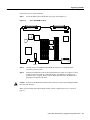
Place the router so the front panel is closest to you. Remove the three screws located on
top of the cover near the front edge. (Figure 2 shows these screws for the Cisco 3620
cover, and Figure 3 shows the screws for the Cisco 3640 cover.) Set the screws aside in a
safe place.
Step 5
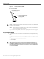
Lift the front edge of the cover about 1 inch (2.5 cm) above the chassis, as shown in
Figure 1.
Figure 1
Lifting the Cover
Screw
SY
ST
EM
RP
H7242
S
CO
N
AU
X
AC
TIV 0 1
RE E
AD
Y
PC
MC
IA
Step 6
1
0
Pull the cover toward you until the metal tabs on the rear edge separate from the chassis
bottom. (See Figure 2 for the Cisco 3620 and Figure 3 for the Cisco 3640.)
6 Cisco 3600 Series Memory Upgrade Configuration Note