1
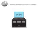
McIntosh Laboratory, Inc.
2 Chambers Street Binghamton, New York
D100
Digital Preamplifier
Owner’s Manual
13903-2699 Phone: 607-723-3512
www.mcintoshlabs.com
The lightning flash with arrowhead, within an equilateral
triangle, is intended to alert the user to the presence of
uninsulated “dangerous voltage” within the product’s enclosure that may be of sufficient magnitude to constitute
a risk of electric shock to persons.
WARNING - TO REDUCE RISK
OF FIRE OR ELECTRICAL
SHOCK, DO NOT EXPOSE
THIS EQUIPMENT TO RAIN OR
MOISTURE.
IMPORTANT SAFETY
INSTRUCTIONS!
PLEASE READ THEM BEFORE
OPERATING THIS EQUIPMENT.
1. Read these instructions.
2. Keep these instructions.
3. Heed all warnings.
4. Follow all instructions.
5. Do not use this apparatus near water.
6. Clean only with a dry cloth.
7. Do not block any ventilation openings. Install
in accordance with the manufacturer’s instructions.
8. Do not install near any heat sources such as
radiators, heat registers, stoves, or other apparatus (including amplifiers) that produce heat.
9. Do not defeat the safety purpose of the polarized or grounding-type plug. A polarized plug
has two blades with one wider than the other.
A grounding type plug has two blades and a
2
The exclamation point within an equilateral triangle is
intended to alert the user to the presence of important
operating and maintenance (servicing) instructions in the
literature accompanying the appliance.
NO USER-SERVICEABLE PARTS
INSIDE. REFER SERVICING TO
QUALIFIED PERSONNEL.
third grounding prong. The wide blade or the
third prong are provided for your safety. If
the provided plug does not fit into your outlet,
consult an electrician for replacement of the
obsolete outlet.
10. Protect the power cord from being walked on
or pinched particularly at plugs, convenience
receptacles, and the point where they exit
from the apparatus.
11. Only use attachments/accessories specified by
the manufacturer.
12. Use only with the cart, stand, tripod, bracket,
or table specified by the manufacturer, or sold with the apparatus. When a cart is used, use
caution when moving the cart/
apparatus combination to avoid
injury from tip-over.
13. Unplug this apparatus during lightning storms
or when unused for long periods of time.
14. Refer all servicing to qualified service personnel. Servicing is required when the apparatus
has been damaged in any way, such as power-
To prevent the risk of electric
shock, do not remove cover or
back. No user-serviceable parts
inside.
supply cord or plug is damaged, liquid has
been spilled or objects have fallen into the
apparatus, the apparatus has been exposed to
rain or moisture, does not operate normally, or
has been dropped.
15. Do not expose this equipment to dripping or
splashing and ensure that no objects filled
with liquids, such as vases, are placed on the
equipment.
16. To completely disconnect this equipment from
the a.c. mains, disconnect the power supply
cord plug from the a.c. receptacle.
17. The mains plug of the power supply cord shall
remain readily operable.
18. Do not expose batteries to excessive heat such
as sunshine, fire or the like.
19. Connect mains power supply cord only to a
mains socket outlet with a protective earthing
connection.
Thank You
Customer Service
Your decision to own this McIntosh D100 Digital Preamplifier ranks you at the very top among discriminating music listeners. You now have “The Best.” The
McIntosh dedication to “Quality,” is assurance that
you will receive many years of musical enjoyment
from this unit.
Please take a short time to read the information in
this manual. We want you to be as familiar as possible with all the features and functions of your new
McIntosh.
If it is determined that your McIntosh product is in
need of repair, you can return it to your Dealer. You
can also return it to the McIntosh Laboratory Service
Department. For assistance on factory repair return
procedure, contact the McIntosh Service Department
at:
Front Panel:
Front Panel Displays, Controls, Push-buttons
and Jack...................................................................... 12
McIntosh Laboratory, Inc.
2 Chambers Street
Binghamton, New York 13903
Phone: 607-723-3515
Fax: 607-723-1917
Operation:
How to Operate the D100..................................... 14-15
Please Take A Moment
The serial number, purchase date and McIntosh Dealer
name are important to you for possible insurance
claim or future service. The spaces below have been
provided for you to record that information:
Serial Number:________________________________
Purchase Date:________________________________
Dealer Name:_________________________________
Technical Assistance
If at any time you have questions about your McIntosh
product, contact your McIntosh Dealer who is familiar
with your McIntosh equipment and any other brands
that may be part of your system. If you or your Dealer
wish additional help concerning a suspected problem,
you can receive technical assistance for all McIntosh
products at:
McIntosh Laboratory, Inc.
2 Chambers Street
Binghamton, New York 13903
Phone: 607-723-3512
Fax: 607-724-0549
Table of Contents
Safety Instructions...................................................... 2
Thank You and Please Take a Moment....................... 3
Technical Assistance and Customer Service.............. 3
Table of Contents........................................................ 3
General Information................................................... 4
Connector and Cable Information.............................. 4
Introduction................................................................. 5
Performance Features................................................. 5
Dimensions................................................................. 6
Installation.................................................................. 7
Setup:
Setup.......................................................................... 13
Additional Information:
Photos.....................................................................16-17
Specifications............................................................. 18
Packing Instruction.................................................... 19
Connections:
Rear Panel Connections............................................... 8
Connecting to a Power Amplifier................................ 9
Connecting to an Analog Preamplifier
or A/V Control Center............................................. 10
Connection Diagrams
(Separate Sheet).................................Mc1A and Mc1B
Remote Control:
Remote Control Push-buttons.....................................11
Copyright 2012 © by McIntosh Laboratory, Inc.
3
General Information and Connector Information
General Information
Connector and Cable Information
1. For additional connection information, refer to the
owner’s manual(s) for any component(s) connected
to the D100 Digital Preamplifier.
2. The Main AC Power going to the D100 and any
other McIntosh Component(s) should not be applied
until all the system components are connected
together. Failure to do so could result in malfunctioning of some or all of the system’s normal operations. When the D100 and other McIntosh Components are in their Standby Power Off Mode, the
Microprocessor’s Circuitry inside each component
is active and communication is occurring between
them.
3. The Fixed Balanced/Unbalanced Outputs and the
variable Balanced/Unbalanced Outputs can be used
simultaneously.
4. The D100 internal Digital to Analog Converter
Circuitry is designed to decode 2-channel PCM
(Pulse Code Modulation) Digital Signal present at
the Coaxial, Optical and USB Digital Inputs. Other
Digital Audio Signal Format Types will cause the
Audio Outputs of the D100 to be muted.
5. The IR Input, with 1/8 inch mini phone jack, is
configured for non-McIntosh IR sensors such as a
Xantech Model HL85BK Kit.
6. When discarding the unit, comply with local rules
or regulations. Batteries should never be
thrown away or incinerated but disposed
of in accordance with the local regulations
concerning battery disposal.
7. For additional information on the D100 and
other McIntosh Products please visit the McIntosh
Web Site at www.mcintoshlabs.com.
XLR Connectors
Below is the Pin configuration for the XLR Balanced
Output Connectors on the D100. Refer to the diagram
for connections:
PIN 1: Shield/Ground
PIN 2: + Output
PIN 3: - Output
4
PIN 1
PIN 3
PIN 2
Power Control
The D100 Power Control In receives and the Power
Control Out sends Power On/
Off Signals (+12 volt/0 volt)
Power
Control
when connected to other McInMeter
tosh Components. An additional
Illumination
connection is for controlling the
Control
Ground
illumination of the Power Output
Meters on McIntosh Power Amplifiers. A 1/8 inch
stereo mini phone plug is used for connection to the
Power Control
Data Input and IR IN Port Connectors
The D100 Data In Port receives
Remote Control Signals from
Data
Signal
McIntosh Preamplifiers and
N/C
A/V Control Centers. A 1/8
Data
inch stereo mini phone plug is
Ground
used for connection.
The IR IN Port also uses a 1/8
Data
inch stereo mini phone plug and al- IR
Control
N/C
lows the connection of other brand
IR Receivers to the D100.
Ground
Introduction and Performance Features
Introduction
The McIntosh D100 Digital Preamplifier is one of the
finest Preamplifiers ever created with connections for
digital sources. The D100 Outputs have the ability to
drive multiple components. The D100 reproduction
is sonically transparent and absolutely accurate. The
McIntosh Sound is “The Sound of the Music Itself.”
Performance Features
• Dual Function
Use the D100 as the Preamplifer together with McIntosh Source Components and Power Amplifier to form
a complete Audio System. Connect the D100 to an
exisiting McIntosh Analog Audio System to provide
the latest in Digital-to-Analog Conversion from digital
audio sources.
• Electronic Input Switching
Electronic Input Switching on all Inputs provides reliable, noiseless, distortion free switching.
• Digital Audio Inputs
The D100 has Coaxial, Optical and USB Digital Inputs to Decode PCM Signals from an external source.
The Coaxial and Optical Inputs process Digital
Signals up to 192kHz with 24Bit resolution. The USB
Input process Digital Signals up to 192kHz with 32Bit
resolution.
• Quad Balanced Digital to Analog Converter
The 8 channel 32-bit, 192kHz Digital to Analog
Converter is used in a Stereo Quad Balanced Mode,
assuring the music is reproduced with a wide dynamic
range and extremely low distortion, for both Disc and
external sources.
• Balanced Outputs
The Balanced Outputs allow the connection of long
cable lengths without a loss in sound quality.
• Precision Tracking Volume Control
Volume levels are controlled by a new Precision Digitally Controlled Attenuator System with a tracking
accuracy of 0.1dB.
• Alphanumeric Fluorescent Display
The Front Panel Information Display indicates the
Source Selection, Sampling Frequency, Bit Depth,
Volume Level and Setup Mode Selections. The display
intensity is adjustable.
• Fiber Optic Solid State Front Panel Illumination
The even Illumination of the Front Panel is accomplished by the combination of custom designed Fiber
Optic Light Diffusers and extra long life Light Emitting Diodes (LEDs).
• Glass Front Panel
The famous McIntosh Illuminated Glass Front Panel
ensures the pristine beauty of the D100 will be retained for many years.
• Remote Control with External Sensor Input
The Remote Control provides control of the D100
operating functions and allows enjoy of your McIntosh
System from another room in your home by connecting an external sensor.
• Power Control Input and Output
A Power Control connection for convenient Turn-On
of McIntosh Power Amplifiers, Source Components
and Accessories is included.
• Special Power Supply
Fully regulated Power Supplies and a special R-Core
Power Transformer ensure stable noise free operation
even though the power line varies.
• Gold Plated Connectors
The Input and Output Connectors Contacts are gold
plated for superior corrosion resistance and high electrical conductivity.
5
Dimensions
Dimensions
The following dimensions can assist in determining
the best location for your D100. There is additional
information on the next page pertaining to installing
the D100 into cabinets.
Front View of the D100
17-1/2"
44.5cm
3-9/32"
5
USB
192
24
8.3cm
3-7/8"
9.8cm
Side View of the D100
13"
33.0cm
1-1/6"
2.7cm
12-1/16"
30.6cm
2-11/32"
6.0cm
29/32"
1.8cm
Rear View of the D100
1-5/8"
4.1cm
17-1/32"
43.3cm
2-11/32"
6.0cm
13-1/4"
33.7cm
6
9-1/16"
23.0cm
1-3/8"
3.5cm
2-17/32"
6.4cm
Installation
Installation
The D100 can be placed upright on a table or shelf,
standing on its four feet. It also can be custom installed in a piece of furniture or cabinet of your
choice. The four feet may be removed from the bottom
of the D100 when it is custom installed as outlined below. The four feet together with the mounting screws
should be retained for possible future use if the D100
is removed from the custom installation and used free
standing. The required panel cutout, ventilation cutout
and unit dimensions are shown.
Always provide adequate ventilation for your D100.
Cool operation ensures the longest possible operating
life for any electronic instrument. Do not install the
D100 directly above a heat generating component such
as a high powered amplifier. If all the components are
installed in a single cabinet, a quiet running ventilation fan can be a definite asset in maintaining all the
system components at the coolest possible operating
temperature.
A custom cabinet installation should provide the
following minimum spacing dimensions for cool
operation.
Allow at least 2 inches (5.08cm) above the top, 2
inches (5.08cm) below the bottom and 1 inch (2.54cm)
on each side of the Preamplifier, so that airflow is not
obstructed. Allow 15 inches (38.1cm) depth behind the
front panel. Allow 1-7/16 inch (3.66cm) in front of the
mounting panel for knob clearance. Be sure to cut out
a ventilation hole in the mounting shelf according to
the dimensions in the drawing.
17-1/8"
43.5cm
D100 Front Panel
Custom Cabinet Cutout
5
Cabinet
Front
Panel
USB
192
2-3/4"
7.0cm
24
Cutout Opening for Custom Mounting
D100 Side View
in Custom Cabinet
Cutout Opening for Ventilation
Support
Shelf
2-19/32"
D100 Bottom View
in Custom Cabinet
6.6cm
Chassis
Spacers
13/16"
2.0cm
10-1/2"
26.7cm
Cutout Opening
for Ventilation
2-27/32"
7.2cm
Note: Center the cutout Horizontally on the unit.
For purposes of clarity, the above
illustration is not drawn to scale.
11-7/8"
30.2cm
14-17/32"
44.5cm
6-9/16"
16.7cm
7
Rear Panel Connections
Connect the D100 power
cord to a live AC outlet.
Refer to information on the
back panel of your D100 to
determine the correct voltage for your unit
IR INput for
signals from a
compatible IR
Room Sensor
DATA IN receives
control data from a
McIntosh Preamplifier
or A/V Control Center
DIGITAL AUDIO INPUTS OPTICAL
INPUTS 2 and 1 for components with
a Digital Audio Optical Output
POWER CONTROL IN receives
turn-on signals from a McIntosh
component.
POWER CONTROL OUT sends
turn-on signals on to another McIntosh Component.
USB DIGITAL AUDIO INPUT
with control signal for connection
to a computer
8
FIXED AUDIO OUTPUTS UNBALANCED
analog audio output signals to a Preamplifier
or A/V Control Center
VARIABLE AUDIO OUTPUTS UNBALANCED
analog audio output signals to a Power Amplifier
DIGITAL AUDIO INPUTS COAXIAL
Inputs 2 and 1 for components with a
Digital Audio Coaxial Output
VARIABLE AUDIO OUTPUTS BALANCED
analog audio output signals to a Power Amplifier
FIXED AUDIO OUTPUTS BALANCED
analog audio output signals to a Preamplifier
or A/V Control Center
Connecting to a Power Amplifier
Connecting to a Power Amplifer
There are two different ways the D100 may be operated in an audio system. The first way as the Main
Audio Preamplifier connected directly to a Power
Amplifier, instructions on this page. The second way
as a Digital to Analog Converter with Input Switching
connecting to an Analog Preamplifier, instructions on
the next page.
The D100 has the ability to automatically switch
power On/Off to Source Components via the Power
Control connections. The Data Port Connections allow
for the remote operation of basic functions using the
D100 Remote Control. With an external sensor connected to the D100, remote control operation of the
system is possible from another room and/or when the
D100 is located in a cabinet with the doors closed.
The connection instructions below, together with
the D100 Connection Diagram located on the separate
folded sheet “Mc1A”, is an example of a typical audio
system. Your system may vary from this, however the
actual components would be connected in a similar
manner. For additional information refer to “Connector and Cable Information” on page 4.
Note: The Power Amplifier may be connected to the
D100 Balanced or Unbalanced Outputs.
Power Control Connections:
1. Connect a Control Cable from the D100 POWER
CONTROL OUT Jack to the Power Control In on
the Tuner.
2. Connect a Control Cable from the Tuner Power
Control Out Jack to the SACD/CD Player Power
Control In Jack.
3. Connect a Control Cable from the SACD/CD Player Power Control Out Jack to the Power Amplifier
Power Control In Jack.
Note: If two Power Amplifiers are used, connect the
Power Control Output of the first Amplifier to
the Power Control Input on the second Amplifier.
4. Connect any additional Components in a similar
manner, as outlined in steps 1 thru 3.
Sensor Connection:
5. Optionally, connect the external Sensor to the
D100 IR Input Connector.
Audio Connections:
6. Connect balanced audio cables from the D100
VARIABLE AUDIO OUTPUT (R&L) connectors to the balanced Input connectors on the Power
Amplifier.
Note: If two Power Amplifiers are used, connect
the unbalanced VARIABLE AUDIO OUTPUT
(L&R) to the unbalanced Inputs on the second
Amplifier.
Digital Audio Connections:
7. Connect a Digital Coaxial Cable from the D100
DIGITAL AUDIO COAXIAL IN 1 Jack to the
Tuner Digital Coaxial Output Jack.
8. Connect a Digital Optical Cable from the D100
DIGITAL AUDIO OPTICAL IN 1 Jack to the
SACD/CD Player Digital Optical Output Jack.
9. Connect a USB cable with (type A to type B) connectors from the D100 DIGITAL AUDIO INPUT
USB to the Computer USB connector.
AC Power Cords Connections:
10. Connect the D100 and any remaining components’
AC Power Cords to a live AC outlet as illustrated.
9
Connecting to an Analog Preamplifier or A/V Control Center
Connecting to an Analog Preamplifier or
A/V Control Center
The D100 has the ability to automatically switch
Power On/Off with the Analog Preamplifier or A/V
Control Center via the Power Control connection. The
Data Port Connections allow for the remote operation
of basic D100 functions using the Analog Preamplifier
Remote Control.
The connection instructions below, together with
the D100 Connection Diagram located on the separate
folded sheet “Mc1B”, is an example of a typical audio
system. Your system may vary from this, however the
actual components would be connected in a similar
manner. For additional information refer to “Connector and Cable Information” on page 4.
Note: The Analog Preamplifier or A/V Control Center
Power may be connected to the D100 Balanced
or Unbalanced Outputs.
Power Control Connections:
1. Connect a Control Cable from the Analog Preamplifier or A/V Control Center to the D100 POWER
CONTROL IN Jack.
2. Connect a Control Cable from the D100 POWER
CONTROL OUT Jack to the Tuner Power Control
In Jack.
3. Connect a Control Cable from the Tuner Power
Control Out Jack to the SACD/CD Player Power
Control In Jack.
4. Connect any additional Components in a similar
manner, as outlined in steps 2 and 3.
Data Connection:
5. Connect a Control Cable from the D100 DATA IN
Jack to the Analog Preamplifier or A/V Control
Center DVD or VIDEO Data Port Input.
10
Sensor Connection:
6. Optionally, connect the external Sensor to the Analog Preamplifier or A/V Control Center IR Input
Connector to the external Sensor.
Audio Connections:
7. Connect balanced audio cables from the D100
FIXED AUDIO OUTPUT (R&L) connectors to
the balanced Input connectors on the Analog Preamplifier or A/V Control Center DVD or VIDEO
Input.
Digital Audio Connections:
8. Connect a Digital Coaxial Cable from the D100
DIGITAL AUDIO COAXIAL IN 1 Jack to the
Tuner Digital Coaxial Output Jack.
9. Connect a Digital Optical Cable from the D100
DIGITAL AUDIO OPTICAL IN 1 Jack to the
SACD/CD Player Digital Optical Output Jack.
10. Connect a USB cable with (type A to type B) connectors from the D100 DIGITAL AUDIO INPUT
USB to the Computer USB connector.
AC Power Cords Connections:
11. Connect the D100, Analog Preamplifier or A/V
Control Center and any remaining components’
AC Power Cords to a live AC outlet as illustrated.
Remote Control Push-Buttons
Press the
area of the push-button to
switch power On or Off to the D100
Press the LEVEL Push-button to
adjust the Volume Level Up or
Down at the D100 Variable Outputs
Connections
HOME
Direct access to the Digital Input (1 - 5)
by using the Front Panel Indicated Input
Number for source selection
Steps thru the Digital Inputs
(1 - 5) for source selection
Note: Push-buttons whose function is not identified above are for use with other McIntosh Products.
11
Front Panel Displays, Controls, Push-buttons and Jack
INPUT Control allows the
selection of digital sources
(1 - 5) for listening
IR Sensor receives
commands from a
Remote Control
INFORMATION DISPLAY
indicates the Source, Volume
Level, Sampling Frequency, Bit
Depth, Operational Functions
and Setup Mode Settings
5
192
24
SETUP Push-button with
indicator, activates the Setup
Mode for changing operational
settings
Connection for low
impedance dynamic
headphones, for
private listening
MUTE Push-button
with indicator, mutes
the audio from the
Loudspeakers
12
USB
LEVEL Control allows
adjustment of the listening
level for both channels
STANDBY/ON
Push-button with
indicator, switches
the D100 ON or OFF
(Standby) and resets
the microprocessors
Setup
How to Operate the Setup Mode
Your McIntosh D100 has been factory configured
allowing for immediate enjoyment of superb audio.
If you wish to make changes to the factory default
settings, a Setup Feature is provided to customize the
operation by using the Front Panel Information Display. Refer to the D100 Front Panel Illustration on the
previous page while performing the following steps.
Note: If the D100 is currently On, proceed to step 2.
1. Press the STANDBY/ON Push-button on the Front
Panel or press the
(Power) Push-button on the
Remote Control to switch On the D100. The D100
will go through a brief startup intialization with
the Front Panel Information Display indicating the
Level percentage (Volume) and then the last used
Input Source. Refer to figures 1 and 2.
LEVEL
76%
Figure 1
1
COAX1
.
.
.
.
.
.
Figure 2
2. Press the SETUP Push-button repeatedly until the
Front Panel Information Display indicates “Firmware V1.00” or higher. Refer to figure 3.
FIRMWARE
V1.00
Figure 3
3. Press the SETUP Push-button to exit from the
Setup Mode. The LED above the SETUP Pushbutton will extinguish and the Front Panel Display
will revert back to its normal display. Refer to
figure 2.
Default Settings
The Default Settings Chart that follows indicates the
Function Name, Default Setting and the Page Number
for additional information.
Default Settings
Function Name
AUTO POWER OFF1
BRIGHTNESS
(Display)
FIRMWARE
1
Setting
Page No.
DISABLED
13
HIGH
13
V_ _.__
13
In some Countries and/or Localities the default setting of
Auto Power Off Feature is ENABLED.
Auto Power Off
The D100 incorporates an Auto Power Off Feature,
which can automatically place the Digital Preamplifier into the Power Saving Standby/Off Mode. This
occurs approximately 30 minutes after there has been
an absence of a Digital Audio Signal on the currently
selected D100 Input. If it is desirable to change the
current Auto Off Setting (Disabled or Enabled) perform the following steps:
1. Press the SETUP Push-button.
2. The Front Panel Display will momentarily indicated “Auto Power Off”. Refer to figure 4.
AUTO
POWER
OFF
Figure 4
3. The display will then indicate the current setting,
either Disabled or Enabled. Refer to figures 5
and 6.
DISABLED
Figure 5
ENABLED
Figure 6
4. Rotate the LEVEL Control either clockwise or
counterclockwise to change the current setting.
5. Press the SETUP Push-button repeatedly until
the LED above the SETUP Push-button is extin-
guished and the Front Panel Information Display
indicates the currently selected digital source
Input. Refer to figure 2.
Brightness
The Front Panel Information Display Brightness may
be changed from the default setting. The D100 will
remember the brightness preference, High (default setting) or Low Illumination. Follow the steps below to
reduce the Display Brightness:
1. Repeatedly press the SETUP Push-button until
“BRIGHTNESSS HIGH” is indicated on the
Front Panel Information Display. Refer to figure 7.
BRIGHTNESS
HIGH
Figure 7
2. Rotate the LEVEL Control to change the Brightness to the Low Setting. Refer to figure 8.
BRIGHTNESS
LOW
Figure 8
3. Press the SETUP Push-button repeatedly until
the LED above the SETUP Push-button is extinguished and the Front Panel Information Display
indicates the currently selected digital source
Input. Refer to figure 2.
Firmware Version
The D100 functionality is controlled by internal
software know as “Firmware”. The current Version of
the Firmware can be identified by utilizing the Setup
Mode.
1. Repeatedly press the SETUP Push-button until
“FIRMWARE V_ _.__” is indicated on the
Front Panel Information Display. Refer to figure 3.
3. Press the SETUP Push-button until the LED above
the SETUP Push-button is extinguished.
13
How to Operate the D100
Power On and Off
The Red LED above the STANDBY/ON Push-button lights to indicate the D100 is in Standby mode.
To switch ON the D100, press the STANDBY/ON
Push-button on the Front Panel or the
(Power On)
Push-button on the Remote Control. The D100 will
go through a brief startup initialization with the Front
Panel Information Display indicating the Level Percentage (Volume) and then the last used Input Source.
Refer to figures 50, 51, 52 and 53. To switch OFF the
LEVEL
or press the appropriate push-button on the Remote
Control. Refer to figures 50 and 53.
Level Control
Rotate the Front Panel LEVEL Control (Volume) or
use the LEVEL Upp or Downq Push-buttons on the
Remote Control for the desired listening level. Refer to
figures 50 and 53.
76%
HOME
Figure 51
1
COAX1
Mute
Press the MUTE Push-button on the D100 Front Panel
to mute the Audio in all outputs except the HEADPHONES Output Jack. Pressing the Mute Push-button
a second time will un-mute the D100.
.
.
.
.
.
.
Headphones Jack
Connect a pair of dynamic headphones to the Headphones Jack with a 1/4” (0.635cm) stereo phone type
plug for private listening. Press MUTE Push-button to
mute the Loudspeakers.
Figure 52
D100 press the STANDBY/ON Push-button on the
Front Panel or the
(Power Off) Push-button on the
Remote Control.
Note: The Headphone Output is optimized for impedances ranging from 20 to 600 ohms.
Source Selection
Rotate the INPUT Control to select the desired source
Figure 53
5
USB
192
Figure 50
14
24
How to Operate the D100
USB Input Operation with a Computer
The D100 USB Input provides the capability to playback music from a computer, when the computer is
connected to the rear panel USB connector.
Note: The USB Input is for direct connection to computer only. To playback music from a USB Drive,
connect the USB Drive to another USB Port on
the computer and select the USB Drive with the
Media Playback Program.
The D100 USB Input is compatible with both PC
Computers using Microsoft® Windows® (XP with
Service Pack 3, Vista with Service Pack 1 and Windows 7) and the Apple® Macintosh® Computers
using OS-10.6 with the latest update.
When using a PC Computer with Windows, a special McIntosh USB Audio Software Driver needs to be
installed on the PC Computer. The driver needs to be
installed before connecting the D100 USB Input to an
USB Port on the computer.
Note: If an Apple Macintosh computer is used with the
D100, no additional driver is required.
The McIntosh USB Audio Windows Driver and
Installation and Operation Guide are available for
download from the McIntosh Web Site:
http://www.mcintoshlabs.com/us/support/Pages/
Manuals.aspx
Under “Product Catorgory” select Preamplifiers
and under “Model Number”
select D100, then click on
“Select”. When the D100
Information appears, download the “McIntosh Audio
Windows Driver Installation and Operation Guide”
and “McIntosh USB Audio
Windows Driver V_ . _”.
Follow the instructions in the
Guide and after the USB Driver is installed, connect
the D100 to the PC Computer.
Note: When computer application programs and various computer hardware components conform
to the Microsoft® Windows® and Apple® Macintosh® standards they should also work well when
used in conjunction with the D100 USB Input. If
you are experiencing difficulty with a specific
computer hardware component or computer application program, contact the manufacturer of
the product.
The D100 Preamplifier Front Panel Information
Display will indicate the Sampling Frequency and
Bit Depth of the incoming digital signal. Refer to
figure 54.
5
USB
192
24
Figure 54
Reset of Microprocessors
In the unlikely event the controls of the D100 stop
functioning while On or the D100 will not switch On,
the microprocessors can be reset by performing the
following:
1. Simultaneously press and hold in the MUTE
and SETUP Push-buttons until the LED indicator above the STANDBY/ON Push-button is
extinguished.
2. To switch the D100 back on, press the On
STANDBY/ON Push-button.
USB Audio Windows Driver
Installation and Operation Guide
McIntosh Laboratory, Inc.
2 Chambers Street Binghamton, New York
13903-2699 Phone: 607-723-3512
www.mcintoshlabs.com
15
16
Photos
17
Specifications
Audio Specifications
Frequency Response
+/-0.5dB from 4Hz to 20,000Hz
+0.5/-3dB from 4Hz to 68,000Hz (Source dependent)
Total Harmonic Distortion
0.0015%
Fixed Output level
2.0Vrms Unbalanced
4.0Vrms Balanced
Variable Output level
0 - 8.0Vrms Unbalanced
0- 16.0Vrms Balanced
Signal To Noise Ratio (A-Weighted)
110dB
Dynamic Range
100dB
Output Impedance
600 ohms Unbalanced and Balanced
Headphone Load Impedance
20 to 600 ohms
Digital Audio Specifications
Digital Input Format
SPDIF (PCM1)
Digital Input Sample Rate
Coaxial and Optical: Up to 192KHz, 24-Bit
USB: Up to 192KHz, 32-Bit
Digital Inputs
Coaxial 1 and 2: 0.5V p-p/75 ohms
Optical 1 and 2: - 15dbm to -21dbm (TOS Link)
USB: USB Type B Connector
1
PCM (Pulse Code Modulation) Digital Signal type used for
CD Discs, etc.
General Specifications
Power Control
12VDC, 25mA
Power Requirements
Field AC Voltage conversion of the D100 is not possible. The D100 is factory configured for one of the
following AC Voltages:
100 Volts, 50/60Hz at 20 watts
110 Volts, 50/60Hz at 20 watts
120 Volts, 50/60Hz at 20 watts
220 Volts, 50/60Hz at 20 watts
230 Volts, 50/60Hz at 20 watts
240 Volts, 50/60Hz at 20 watts
Standby Power, less than 0.25 watts
Note: Refer to the rear panel of the D100 for the correct
voltage.
Overall Dimensions
Width is 17-1/2 inches (44.45cm)
Height is 3-7/8 inches (9.8cm) including feet
Depth is 16 inches (40.64cm) including the Front
Panel, Knobs and Cables
Weight
13.5 pounds (6.1 kg) net, 28 pounds (12.7 kg) in shipping carton
Shipping Carton Dimensions
Width is 26-1/2 inches (67.3cm)
Height is 11-3/4 inches (29.9cm)
Depth is 24-1/4 inches (62.2cm)
18
Packing Instructions
Packing Instructions
In the event it is necessary to repack the equipment for
shipment, the equipment must be packed exactly as
shown below. It is very important that the four plastic feet are attached to the bottom of the equipment.
This will ensure the proper equipment location on the
bottom pad. Failure to do this will result in shipping
damage.
Use the original shipping carton and interior parts
only if they are all in good serviceable condition. If
a shipping carton or any of the interior part(s) are
needed, please call or write Customer Service Department of McIntosh Laboratory. Refer to page 4. Please
see the Part List for the correct part numbers.
Quantity
1
4
Part Number
033838
033837
Description
Shipping carton only
End cap
1
1
1
1
2
033836
033725
034301
034547
034446
Inside carton only
Top pad
Bottom pad
Bottom filler pad
Foam plug
4
4
4
017937
400159
404080
Plastic foot
#10-32 x 3/4” screw
#10 Flat washer
FOAM PLUG
19
McIntosh Laboratory, Inc.
2 Chambers Street
Binghamton, NY 13903
www.mcintoshlabs.com
The continuous improvement of its products is the
policy of McIntosh Laboratory Incorporated who
reserve the right to improve design without notice.
Printed in the U.S.A.
McIntosh Part No. 04138700