1
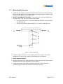
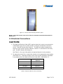
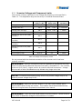
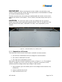
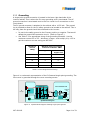
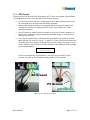
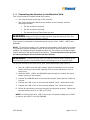
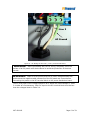
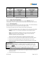
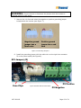
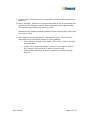
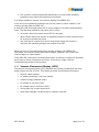
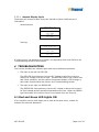
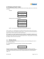
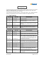
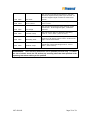
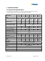
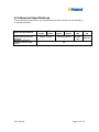
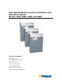
Grid Tied Residential Inverter Installation and
Operations Manual
Models 1100, 2000, 2800, and 3000
Contact Information
PV Powered, Inc.
150 Scalehouse Loop #101
Bend, OR 97702
Phone: 541-312-3832
Fax: 541-383-2348
Toll Free: 877-312-3832
Email: [email protected]
Table of Contents
IMPORTANT SAFETY INSTRUCTIONS ................................................................. 4 1 INTRODUCTION ....................................................................................... 5 2 INSTALLATION ......................................................................................... 5 2.1 Selecting a Location for the Inverter .................................................... 5 2.2 Mounting the Inverter ........................................................................ 5 2.2.1 2.3 3 Mounting the Inverter .................................................................... 6 Electrical Connections ........................................................................ 7 2.3.1 Inverter Voltage and Frequency Limits .............................................. 8 2.3.2 Separation of Circuits ..................................................................... 9 2.3.3 Grounding ...................................................................................10 2.3.4 GFI Circuit ...................................................................................11 2.3.5 Connecting the Inverter to the Electrical Grid ....................................12 OPERATION ............................................................................................17 3.1 Start-Up Procedures for the Inverter ...................................................17 3.2 Inverter Front Panel Status Indicators .................................................17 4 3.2.1 LED Indicator Lights ......................................................................17 3.2.2 Vacuum Fluorescent Display (VFD) ..................................................18 TROUBLESHOOTING ................................................................................19 4.1 Red and Green LED Lights ON ............................................................19 4.2 Displayed Fault Codes ......................................................................20 5 4.2.1 Multiple Faults ..............................................................................20 4.2.2 Fault Code List .............................................................................21
SPECIFICATIONS .....................................................................................23 5.1 Operational Specifications .................................................................23 5.2 Abnormal Specifications ....................................................................24 6 LIMITED WARRANTY ................................................................................25 6.1 Term of Coverage ............................................................................25 6.2 Coverage ........................................................................................25 6.3 What is Not Covered.........................................................................25 6.4 Disclaimer and Limitation of Liability ...................................................26 6.5 Arbitration ......................................................................................26 6.6 Miscellaneous Provisions ...................................................................27 V97-600002
Page 2 of 31
7 7.1 RETURN PROCEDURE ...............................................................................28 Information about Your System .........................................................28 V97-600002
Page 3 of 31
IMPORTANT SAFETY INSTRUCTIONS
This product has been engineered and manufactured to ensure your personal safety.
Improper use may result in potential electrical shock or burns. Please read and
follow all instructions for installation, use and servicing of this product.
NOTE: A locking tab has been designed into the PV Powered Grid Tied Residential
Inverter line. It is the sole responsibility of the end user to provide a locking
mechanism that utilizes the tab, and secures the cover on the inverter.
SAVE THESE INSTRUCTIONS – This manual contains important
instructions for the PV Powered Grid Tied Residential Inverter product line
that must be followed during installation and maintenance of these
inverters.
CAUTION:
•
All electrical installations should be done in accordance with local electrical
codes and the National Electrical Code (NEC), ANSI/NFPA 70.
•
Before connecting the inverter to the electrical utility grid, your utility
company must grant approval. Only qualified electricians should make the
connection.
•
When exposed to light, photovoltaic (PV) arrays create electrical energy that
could cause a hazardous condition. To avoid this, completely cover the
surface of all PV arrays with opaque (dark) material before wiring them.
•
The inverter contains no user-serviceable parts. Refer maintenance to
qualified service personnel.
•
Do not touch the heat sink located at the top of the inverter, temperatures
can exceed 158°F (70°C).
FCC Compliance:
The PV Powered Grid Tied Residential Inverters have been tested and found to pass
FCC Class B radio interference standards with proper installation of the inverter. This
is not a guarantee that there will be no interference at every installation. If you
notice interference at your installation, try the following potential solutions:
•
Move or re-orient the affected device.
•
Increase the distance between the devices.
•
Connect the device to a different AC circuit.
Please read all safety warnings and instructions before
installing or operating the inverter.
SAVE THESE INSTRUCTIONS
V97-600002
Page 4 of 31
1 INTRODUCTION
The PV Powered Grid Tied Residential Inverter is a utility interactive inverter for
photovoltaic (PV) systems.
The inverter is tied to an electrical source provided by the local utility company as
well as to the PV system. The inverter contains everything needed to convert the DC
voltage generated by the PV arrays into the AC voltage required to power a house.
This manual provides information necessary for the successful installation and use of
the PV Powered Grid Tied Residential Inverter.
2 INSTALLATION
2.1 Selecting a Location for the Inverter
When choosing a location for the inverter, consider the following criteria:
•
The inverter is suitable for both indoor and outdoor installation; the inverter
enclosure has a NEMA 3R rating.
•
The optimum location of the inverter is outside, shielded from direct exposure
to sunlight (i.e. not on the south facing side of the building).
•
The heat sink temperatures can exceed 158°F (70°C). The inverter must be
installed so that people will not touch the top of the unit.
•
The inverter is designed to handle the temperature extremes of most
climates. The operating and non-operating environmental ambient
temperature range is -15°F to 105°F (-25°C to 40°C).
•
The following clearances are recommended for proper placement of the
inverter:
•
•
A minimum of 36″ between the bottom of the inverter box and the
ground.
•
A minimum of 12” above the heat sink.
•
Visibility of the operating LEDs and display located at the top front of
the inverter box should also be considered.
If the inverter is installed in an enclosed space, adequate ventilation must be
provided.
2.2 Mounting the Inverter
The inverter should be mounted vertically to a flat, solid surface such as wallboard,
concrete, or wood siding. The inverter should be located near the PV arrays to
minimize the DC wire length.
The mounting bracket provided makes mounting the inverter quick and simple. The
2 screw holes at either end of the bracket are 16” apart. Once the wall studs are
located, anchoring the bracket becomes an easy task.
WARNING: Before drilling holes to mount the inverter, verify that there are no
electrical wires or plumbing in the area.
V97-600002
Page 5 of 31
2.2.1 Mounting the Inverter
1. Locate the wall studs in the desired location and align the mounting bracket
over the studs. Mark the mounting holes. Ensure that locations A and B (see
Figure 1) are aligned over the wall studs.
2. VERIFY THE BRACKET IS LEVEL. Ensure points A and B are aligned with
the wall studs. Drill 1/8” pilot holes for the screws.
•
Use heavy-duty 1/4" x 2” coarse thread lag screws to secure points A
and B to the wall.
•
Use an 1/8” screw to secure points C, D, E, and F (See Figure 1).
A
B
C
D
E
F
Mounting
hole
Figure 1: Mounting Bracket
3. Carefully hang the inverter on the upper part of the bracket. The hooks
located at the rear of the inverter should hang over the bracket.
4. Verify inverter is level.
5. Remove the front cover of the inverter by unscrewing the four cover screws
located around the front perimeter of the inverter.
6. Locate the inverter mounting hole below the power board. Insert the
mounting screw through the inverter and tighten securely.
V97-600002
Page 6 of 31
Figure 2: Inverter with mounting bracket in place
NOTE: Leave the inverter cover off to allow for electrical connections described in
Section 2.3.
2.3 Electrical Connections
CAUTION:
1. The National Electrical Code (NEC) requires that the inverter be connected to
a dedicated circuit with no other outlets or devices connected to the same
circuit. See NEC Section 690-64(b)(1). The NEC also places limitations on
the size of the inverter and the manner in which it is connected to the utility
grid. See NEC Section 690-64(b)(2).
See Table 2.1 for more information on required branch circuit protection.
2. To reduce the risk of fire, connect the inverter to the appropriate size breaker
(See Table 2.1). Maximum branch-circuit over-current protection calculated
in accordance with the National Electrical Code (NEC), ANSI/NFPA 70.
Inverter model
Circuit breaker
required
PVP 1100
1 pole 15 A
PVP 2000
2 pole 15 A
PVP 2800
2 pole 20 A
PVP 3000
2 pole 20 A
Table 2.1Required Branch Circuit Protection
V97-600002
Page 7 of 31
2.3.1 Inverter Voltage and Frequency Limits
The inverter is factory-calibrated to the voltage and frequency limits specified in
Table 2.2. This adjustable range can be set by PV Powered field technicians.
Condition
Factory setting
(VAC) or (Hz)
Adjustable
Range (VAC)
Maximum
trip time(s)
Voltage phase high
132.0
132.0 - 142.0
< 1 second
Voltage phase low
105.6
95.6
< 2 seconds
Voltage phase fast high
144.0
144.0 - 156.0
< 160mS
Voltage phase fast low
60.0
<60.0
< 160mS
Voltage high Line to Line (240V
inverters)
264.0
Voltage low Line to Line (240V
inverters)
211.0
Voltage high Line to Line (208V
inverters)
228.8
Voltage low Line to Line (208V
inverters)
183.0
- 105.6
Line Frequency Low
59.3 Hz
n/a
< 160mS
Line Frequency High
60.5 Hz
n/a
< 160mS
Table 2.2 Voltage and Frequency Limits
Do not proceed with the electrical connection of the inverter until it has been
properly mounted.
WARNING:
Electrical connections must be completed in accordance with local
electrical codes and the National Electrical Code (NEC), ANSI/NFPA 70. Use 10 AWG,
minimum 90°C (194°F), copper wire for all inverter electrical connections. Voltage
drop as well as other considerations may dictate using larger wire sizes.
NOTE: PV Powered recommends sizing wire of one percent voltage drop for AC
and one percent voltage drop for DC.
WARNING:
Make sure the main breaker in the main utility breaker box is
switched OFF before wiring the inverter. This breaker should be switched ON only
after all wiring has been completed as described in this manual.
WARNING:
Follow the order listed below to wire the inverter. Failure to do so
may result in hazardous voltages or disconnection of contacts.
V97-600002
Page 8 of 31
IMPORTANT: When mounting the inverter outside, use rain-tight or wetlocation conduit hubs that comply with the requirements in the Standard for Fittings
for Conduit and Outlet Boxes, UL 514B.
Terminal connections for the inverter are located inside the inverter on the circuit
board at the bottom of the cabinet. The AC and DC terminals accept wires up to 6
AWG.
CAUTION:
The input and output circuits are isolated from the enclosure.
System grounding, when required by Sections 690-41, 690-42, and 690-43 of the
National Electric Code (NEC), ANSI/NFPA 70-1999, is the responsibility of the
installer.
Figure 3: Communications, AC, and DC ports
2.3.2 Separation of Circuits
The lower part of the inverter circuit board is divided into three sections.
1. The left side is dedicated to the low voltage DC communications.
2. The center is dedicated to the AC.
3. The right side is dedicated to the DC.
Each section has two to three knockouts as shown in Figure 3. UL 1741 standard
requires a straight run of wire, with no loops or crossover to the other circuits
(sections) and low voltage versus high voltage in each section.
1. Left knockouts (up to the divider) are for low voltage communications only
(PVM1010).
2. Center knockouts are for AC.
3. Right knockouts are for DC.
V97-600002
Page 9 of 31
2.3.3 Grounding
A single-point ground connection is located in the lower right-hand side of the
inverter cabinet. This is where the PV array grounding wire is terminated. The AC
ground connection is terminated next to the Line 1 and Line 2 connections on the
circuit board.
The PV ground connector is attached to the cabinet with a 10-32 bolt. This ground
lug is provided to allow for the PV safety ground to be bonded to the cabinet. This is
the only place the ground should be connected to the inverter.
•
Do not tie the safety ground to the PV array positive or negative. That would
defeat the ground fault protection circuit. (Refer to Figure 5.)
•
See Table 2.3 for appropriate sizing of the grounding electrode. Use the
maximum current AC or DC - whichever is larger - and multiply it by 1.25 to
get the maximum current rating per NEC 690.
Maximum
current
rating
Minimum size of grounding
electrode conductor AWG
Copper
Aluminum
Copper clad
15
8
6
20
8
6
30
8
6
40
8
6
60
8
6
Table 2.3 Grounding Electrode Sizing
Figure 4 is a schematic representation of the PV Powered single-point grounding. The
front cover is grounded through the cover mounting screws.
+
Control pcb
Power Distribution PCB
GF Detect Circuit
PV
DC input
120/240 VAC
60Hz
1A
Line
Filter
-
L1
20 A SB
DC
Power
Supply
PV GND
L2
GND
GND
System Block Diagram
Figure 4: System Block Diagram showing single-point ground
V97-600002
Page 10 of 31
2.3.4 GFI Circuit
The purpose of the Ground Fault Interrupter (GFI) circuit is to detect a ground fault
(unintended current flow from the PV arrays to earth ground).
•
For the GFI circuit to function as designed, the PV array safety ground must
be connected only at the ground terminals provided.
•
Bonding the safety ground to the grounded leg of the array anywhere but
through the inverter will bypass the GFI circuit. This creates an unsafe
operating condition.
•
The GFI works by using a fuse to connect or bond the PV array negative (or
the PV array positive if using a positively grounded array) to earth ground
through the 1 A fuse.
•
If current is greater than 1 A between the grounded array terminal and the
earth ground, the fuse will “blow”. A “blown” or open fuse will disconnect the
PV arrays from their ground reference and interrupt the ground fault current.
In this situation, the inverter will cease operation and display a fault message
(as illustrated below):
Fault 0400 0000
Ground Fault
If the inverter displays “Ground Fault”, turn OFF the AC and DC to the
inverter and refer to the Troubleshooting section of this manual.
AC Ground
PV Ground
Figure 5: AC and PV Grounding
V97-600002
Page 11 of 31
2.3.5 Connecting the Inverter to the Electrical Grid
Two circuit boards are located inside the Inverter:
•
The Control Board (at the top of the inverter).
•
The Power Distribution Board (at the bottom of the inverter) with the
following terminals:
•
The AC connection terminal.
•
The DC connection terminal.
•
The internal Ground Fault Interrupt fuse.
WARNING: Replace the GFI fuse with the same type and rating of fuse. The
inverter uses only Littelfuse KLKD001 1A/600V.
The inverter is connected to the electrical grid using 3 wires - LINE 1, LINE 2 and
GROUND.
NOTE: To avoid an increase in AC voltage to unacceptable values while the inverter
is connected, the grid impedance value at the connection point should be as low as
possible. By keeping the grid impedance value low, the inverter will achieve higher
system efficiency and avoid nuisance shutdowns. The total impedance of the grid plus
the interconnecting AC wires should be less than 1.25 Ohm.
WARNING:
Ensure the main 240V (or 208V for the PVP 2800) breaker at the
circuit breaker panel is switched OFF before connecting to the AC terminal block.
To wire the inverter to the main utility grid, follow these steps (see Figure 6):
1. Run the conduit from the main breaker panel to the bottom of the inverter.
Insert the fitting in the center opening of the inverter and fasten it with a
locking nut.
2. Feed the LINE 1, LINE 2 and GROUND wires through the conduit and into a
center opening of the inverter.
3. Connect the GROUND wire to the terminal marked “earth ground” inside the
inverter.
4. Connect the LINE 2 wire to the terminal marked “line 2” inside the inverter.
5. Connect the LINE 1 wire to the terminal marked “line” inside the inverter.
6. Ensure all connections are wired correctly and properly torqued. Tighten the
terminal block screws to 0.5 Nm (0.37 ft-lb).
NOTE: In the PVP1100 units, LINE 1 wire is the only phase voltage wire, LINE 2
is neutral, and LINE 3 is the AC GROUND.
V97-600002
Page 12 of 31
Line 1
Line 2
AC Ground
Figure 6: AC Wiring for the Line 1, Line 2, and Ground Wires
WARNING: Before proceeding with the DC wiring, completely cover the
surface of all PV panels with dark material to avoid the production of electrical
current.
WARNING:
Make sure the polarity and the PV panel voltage between the
positive and the negative cable connectors of the PV panels are correct before
connecting the panels to the DC terminal block on the power distribution board.
The PV array open circuit voltage should be at or below the listed voltages in Table
2-4 under all circumstances. Each DC input to the DC terminal block must be less
than the voltages listed in Table 2-4.
V97-600002
Page 13 of 31
Inverter
Model
Maximum inverter
start voltage
Absolute maximum
input voltage
PVP1100
450VDC
500VDC
PVP2000
450VDC
500VDC
PVP2800
450VDC
500VDC
PVP3000
450VDC
500VDC
Table 2.4: PV Open Circuit Voltages
2.3.5.1 Open Circuit Calculations
The PV array open circuit voltage should be at or below 500 VDC under all
circumstances. Each DC input to the DC terminal block must be less than 500 VDC.
2.3.5.2 DC Connections
Each DC input connection must carry the same input voltage. The inverter allows up
to three connections for both the positive and negative poles.
To wire the DC inputs from the PV array to the inverter (see Figure 8):
1. Calculate the maximum open circuit voltage (Voc) for each series of modules
based on the VOC_TC, the ambient temperature, and accepted industry
practice.
Note: For all temperature conditions, the Voc for each series connection
must total less than the VDC indicated in Table 2-4 for the PVP1100,
PVP2000, PVP2800, and PVP3000 models.
Review the PV panel’s data sheet for operating temperature ranges.
2. Keep track of the array positive and negative leads and mark them clearly.
3. Route the PV array leads through the far right opening in the inverter.
4. Connect each series positive DC lead to the positive terminals of the power
distribution board.
WARNING:
Negative grounded array: On a standard negatively grounded PV array, only
break only the positive wire(s) in the DC disconnect. Do NOT break the negative
wire(s)..
Positive grounded array: On a positively grounded PV array, only break only the
negative wire(s) in the DC disconnect. Do NOT break the positive wire(s).
5. Connect the negative DC leads directly to the negative terminal on the power
distribution board.
6. Connect the ground wire(s) to the ground lug.
V97-600002
Page 14 of 31
WARNING:
Do not connect or disconnect the jumper while the inverter is
supplied with DC or AC power.
7. Remove the 1 A fuse and select the negative or positive grounding jumper
included with the inverter (see Figure 7).
Negative ground
jumper has a
black wire
Positive ground
jumper has a red
wire
Figure 7 Grounding Jumpers
8. Install the grounding jumper with the white wire on the right into connector
J3 on the power board (see Figure 8).
GFI Jumper (J3)
Fuse Clips
V97-600002
Figure 8 Power Board Connections
PV Positive
PV Negative
Page 15 of 31
9. Confirm that the DC disconnect is turned OFF and remove the material from
the array.
10. With a voltmeter, check the PV array positive leads in the DC disconnect and
confirm that the voltage is positive when referenced to the negative leads.
The reading should match your series Voc total.
Measure the DC voltage potential between the two mounting clips (see Figure
8) for the 1 A fuse.
11. The voltage should be less than 25 volts absolute value. The DC and AC
disconnect can be turned OFF and the 1 A fuse installed.
•
If the voltage is outside of this range (-25V to 25V), wait 10 minutes
and check again.
•
If (after 10 minutes) the voltage is still not in the range of -25V to
25V, check for a ground fault or other incorrect wiring.
•
If the problem continues to persist, contact PV Powered Technical
Support.
V97-600002
Page 16 of 31
3 OPERATION
3.1 Start-Up Procedures for the Inverter
WARNING:
Before turning ON the inverter, ensure that the front panel is
closed properly.
WARNING:
The heat sink can reach temperatures in excess of 158ºF (70ºC).
Do not touch the heat sink when in use, and do not place anything on top of the heat
sink.
To start up the inverter, complete the following steps in the order indicated:
1. Turn the AC breaker ON.
2. Verify that the RED LED light is illuminated.
3. Check the polarity to ensure the positive and negative are wired correctly,
and confirm that the PV array open circuit voltage is at or below the level
specified in Table 2-4.
4. Turn the DC disconnect ON.
Note: PV Powered recommends that a padlock be attached to prevent
unauthorized access or damage to the inverter.
5. After five minutes, the inverter will start to produce power if all necessary
operating conditions are met.
3.2 Inverter Front Panel Status Indicators
3.2.1 LED Indicator Lights
The inverter has two LED indicator lights visible through the upper left corner of the
front panel. These lights indicate the inverter’s status.
•
If the inverter’s operating environment is safe to export power into the AC
grid, the GREEN LED is illuminated.
•
If the operating environment moves outside the safe operating limits
governed by UL 1741, IEEE 1547, IEEE 519, and NEC 690, the RED LED
indicator is illuminated.
The inverter continuously monitors:
1. The AC grid connection, to ensure the AC voltage and frequency levels are
within safe operating limits per UL1741.
2. The DC voltage and current from the PV array ensuring safe operating
conditions per UL 1741.
V97-600002
Page 17 of 31
3. The inverter’s internal operational parameters, to ensure safe operating
conditions exist within the operating environment.
If all three conditions are met, the inverter displays the GREEN LED.
If any one of the operating conditions are not met, there is a fault condition. The
inverter will then flash the RED LED.
A solid RED LED illuminates when the PV array voltage is not within safe operating
limits. The following conditions may cause this to occur:
•
At sunset, when the inverter turns OFF for the night.
•
When clouds reduce the amount of available sunlight or when portions of the
PV array are covered with snow.
•
Any time the DC output from the PV array drops below the inverter’s
minimum DC operating voltage, the inverter turns OFF.
When the array is once again exposed to enough sunlight, the GREEN LED
illuminates, the inverter’s auto-start feature begins, and after five minutes the
inverter begins to export power.
If the RED LED continues to illuminate when there is sufficient sunlight for operation,
verify that no wiring connections are loose. If the wiring is tight, see the
Troubleshooting section of this manual.
3.2.2 Vacuum Fluorescent Display (VFD)
The vacuum fluorescent display (VFD) indicates the inverter’s status and real-time
power output into the AC Grid. This display provides the following information:
•
Inverter model number.
•
AC power produced in real-time (Watts).
•
Lifetime energy produced (kWh).
•
AC voltage in real time (VAC).
•
PV voltage input in real-time (VDC).
•
During start-up, a count down timer.
•
Fault code message if a fault exists or recently occurred.
V97-600002
Page 18 of 31
3.2.2.1 Normal Display Cycle
The display will change screens every two seconds to show a different set of
information.
Normal startup:
2000 Watt PV
Start in 269 sec
0 Watts
3212 kWh
240 VAC
297 VDC
Running:
2000 Watt PV
Grid Tied Inv
1245 Watts
3212 kWh
241 VAC
255 VDC
If a fault occurs, the display also provides a corresponding fault code. Refer to the
Troubleshooting section of this manual.
4 TROUBLESHOOTING
The inverter provides two indicator lights that help troubleshoot problems.
•
The light on the left is a RED LED.
The RED LED illuminates any time the DC voltage is below the inverters
startup DC voltage, such as at night. The RED LED blinks if the inverter has
had a fault condition, and the vacuum fluorescent display (VFD) displays a
fault code. Possible faults are listed in this Troubleshooting section.
•
The light on the right is a GREEN LED.
The GREEN LED illuminates any time the DC voltage is above the inverter’s
DC start voltage and all operational parameters are met. When the GREEN
light illuminates, the inverter tries to invert power from the PV array.
4.1 Red and Green LED Lights ON
If this condition occurs (both lights are on solid at the same time), contact PV
Powered for technical assistance.
V97-600002
Page 19 of 31
4.2 Displayed Fault Codes
The vacuum fluorescent display (VFD) provides the following codes when a fault has
occurred:
Faulted:
Fault 1000 0400
AC Voltage High
0 Watts
1400 kWh
267 VAC
300 VDC
Starting up from a faulted state:
2000 Watt PV
Start in 269 sec
Fault 1000 0400
AC Voltage High
0 W
1400 kW-hr
240 VAC
300 VDC
NOTE: In this case the fault refers to the last fault detected.
If the inverter is in a faulted state, the RED LED blinks and the VFD scrolls through
the screens shown in the faulted example above. The text of the fault describes the
specific fault condition that the inverter experienced.
If the inverter is no longer experiencing the condition that caused it to fault (ex. the
AC voltage climbs above 264V then drops below 264V), the RED LED stops blinking
and the inverter starts the five minute count-down timer. During these five minutes,
the display will also show the last fault.
4.2.1 Multiple Faults
If the inverter detects multiple faults at one time, the inverter displays the text of
the first fault detected.
For multiple faults, the numerical values of the fault codes are added.
Example:
Fault 1000 0420
AC Voltage High
The above example displays the AC Voltage High fault (1000 0400), plus a DC
Voltage Low fault (1000 0020). This might occur at night, when the panel voltage is
low (because of darkness) and the utility voltage was above the limits defined in
Table 2.2.
V97-600002
Page 20 of 31
Fault 1200 0040
Power Low
The above example shows a Power Low fault. After the fault occurrence, the inverter
had a DC Voltage High fault. In this case, the display added the fault codes 0200
0000 plus 1000 0040 to become 1200 0040.
If the faults have the same first digit – such as 1000 XXXX – the 1 remains the same
and only the second block of four numbers will add to the original fault code.
4.2.2 Fault Code List
Fault Code
VFD Text
Fault Description
8000 0000
Power Module
Generated by the power electronics module to
protect the module.
4000 0000
Power Module
Generated by the power electronics module to
protect the module.
1000 0800
PLL Fault
The inverter was unable to match the grid
frequency. This is usually caused by an unstable
power grid.
1000 0400
AC Voltage High
The grid voltage exceeded the limits in table 2.2.
1000 0200
AC Voltage Low
The grid voltage dipped below the AC limits in
table 2.2.
Fault Code
VFD Text
Fault Description
1000 0100
AC Freq Low
The grid frequency went below the limits in table
2.2.
1000 0080
AC Freq High
The grid frequency went above the limits in table
2.2.
DC Voltage Low
The DC voltage is below the startup voltage. This
fault is only seen in conjunction with another fault
(ex. 1000 0220 is an AC low and a DC low). DC
could be low because of low light conditions or the
DC disconnect is turned off.
1000 0010
DC Voltage High
DC Voltage is above 500V. Turn the DC disconnect
off immediately. The inverter will restart when the
voltage is back within safe operating conditions.
1000 0002
Power Supply +15
Housekeeping DC power supply 15VDC is out of
tolerance.
1000 0001
Power Supply +5
Housekeeping DC power supply 5VDC is out of
tolerance.
Ground Fault
The inverter detected that the GFI fuse is blown.
Check section 4.2 to troubleshoot. This fault
requires an AC power cycle to reset.
Power Low
The inverter shut down because it was producing
less than 60W for 5 minutes. It will try to restart
in 10 minutes.
1000 0020
0400 0000
0200 0000
V97-600002
Page 21 of 31
0100 0000
CPU Fault
The inverter encountered a problem in the CPU.
This fault requires an AC power cycle to reset. If
this fault happens again contact PV Powered for
service.
0040 0000
Over Current
Safety protection; the inverter tried to produce too
much current.
0020 0000
Pre-charge
The inverter experienced trouble starting up the
transformer. If this happens again, contact PV
Powered.
0004 0000
Heatsink Temp
The heat sink is above or below the operating
limits of -15°F to 200°F (-25°C to 95°C).
Watchdog Fault
The CPU experienced a watch dog fault. This fault
requires an AC power cycle to reset. If this occurs
again contact PV Powered.
Ambient Temp
The temperature detected inside the inverter is
outside the normal operating limits of -15°F to
200°F (-25°C to 95°C).
0002 0000
0001 0000
WARNING:
These servicing instructions are for qualified personnel only. To reduce
the risk of electric shock, do not perform any servicing other than that specified in the
operating instructions unless you are qualified.
V97-600002
Page 22 of 31
5 SPECIFICATIONS
5.1 Operational Specifications
The specifications detailed below are expected operational parameters, and should
be used in designing your PV system in accordance with the NEC.
Specifications
PVP1100120 EV
PVP1100120
PVP2000240 EV
Maximum DC Input Voltage
(VOC)
PVP2000240
PVP2800208
PVP3000240
500VDC
DC Voltage Operating Range (V)
115VDC450VDC
150VDC450VDC
115VDC450VDC
150VDC450VDC
180VDC450VDC
170VDC450VDC
DC MPPT range (V)
115VDC380VDC
150VDC380VDC
115VDC380VDC
150VDC380VDC
180VDC380VDC
170VDC380VDC
10A
8A
18A
14A
17A
18A
183V228.8V
211V-264V
208V
240V
DC Imp Maximum Current (A)
DC Isc Maximum Current (A)
AC Operating Range (V)
26A
105.6V132.5V
26A
105.6V132.5V
AC Frequency Range (Hz)
AC Nominal Voltage (V)
211V-264V
211V-264V
59.3Hz-60.5Hz
120V
120V
240V
240V
Normal Output Frequency
60Hz
Synchronization in rush current
<2.0A
Power Factor
AC Maximum Continuous
Current (A)
Recommended Breaker Size
Output Overcurrent Protection
Continuous Output Power
(Watts)
Maximum Continuous Output
Power (Watts)
Enclosure
0.99 - 1.0 at >50% Power
9.5V
9.5A
9A
9A
14A
13A
15
15
15
15
20
20
20A
1100
1100
2000
2000
2800
3000
1100
1100
2000
2000
2800 3000
Aluminum-NEMA 3R to UL 50 Standards
Dimensions (WxDxH)
Weight
Cooling
Relative Humidity
Ambient Temperature Range
Environmental Rating
Listings
V97-600002
15” x 7.5” x 21.75”
55
55
65
65
80 Natural Convection
0% to 100% Condensing
-25°C to +40°C
NEMA 3R
UL 1741, IEEE 1547, IEEE 519, IEEE 929, IEEE 620
Page 23 of 31
80
5.2 Abnormal Specifications
The specifications listed below are classified as abnormal and are not representative
of normal operation.
Abnormal Specifications
Momentary current transient
obtained during abnormal
operation
Maximum input source
backfeed current to input
source
V97-600002
PVP1100120 EV
PVP1100120 SV
100 A-pk / 0.54 mS
PVP2000240 EV
PVP2000240 SV
142 A-pk / 0.663 mS
PVP2800208
PVP3000240
50 A-pk
for 0.600
mS
166 A-pk /
0.608 mS
0A
Page 24 of 31
6 LIMITED WARRANTY
PV Powered, Inc. provides a limited warranty for your residential or commercial
inverter and optional data monitoring module for defects caused by material or
manufacturing flaws. The inverter and the data monitoring module must be installed
and maintained by a qualified installer in order for the warranty to be valid.
6.1 Term of Coverage
The warranty period for the inverter is ten years, and the warranty on the data
monitoring module is one year, each beginning on the date of purchase by the
original end user.
6.2 Coverage
PV Powered will, at its option, repair or replace the defective component(s) free of
charge, provided that you notify PV Powered of the defect during the warranty
period, have a dated proof of purchase, and PV Powered determines that the defect
is covered by the limited warranty set forth above. PV Powered reserves the right to
inspect the defective component(s) and determine if the defect is due to material or
manufacturing flaws. PV Powered also reserves the right to charge a fee for service
time expended if the defect is not due to material or manufacturing flaw or is not for
some other reason subject to this limited warranty.
PV Powered will, at its option, use new and/or reconditioned parts in performing
warranty repair and in building replacement products. PV Powered reserves the right
to use parts or products of original or improved design in the repair or replacement.
If PV Powered repairs or replaces a product, its warranty continues for the remaining
portion of the original warranty period or 90 days from the date of the return
shipment to the customer, whichever period expires later. All replaced products and
all parts removed from repaired products become the property of PV Powered.
For defects covered by this limited warranty, PV Powered will provide, at no
additional cost to the customer, both parts and labor necessary to repair the product,
and return shipment to the customer via a PV Powered selected, non-expedited,
surface freight carrier within the United States and Canada.
6.3 What is Not Covered
PV Powered does not warrant its products from any and all defects or damage
caused by:
•
Normal wear and tear.
•
Shipping or transportation damages.
•
Improper installation.
•
Improper maintenance.
•
Excessive voltage or current conditions from the electrical grid or PV panels.
V97-600002
Page 25 of 31
•
Exposure to unsuitable environmental conditions (including but not limited to
damage due to lightning strikes, storm, fire, flood, etc.).
•
Unauthorized or abnormal use, repair, modification, or operation.
•
Negligence or accidents.
•
Material or workmanship not provided by PV Powered or its authorized service
centers.
This warranty also does not cover costs related to the removal, installation, or
troubleshooting of your electrical systems.
6.4 Disclaimer and Limitation of Liability
EXCEPT FOR THIS EXPRESS LIMITED WARRANTY, PV POWERED EXPRESSLY
EXCLUDES ALL WARRANTIES WITH RESPECT TO THE INVERTER AND DATA
MONITORING MODULE, EXPRESS AND IMPLIED, INCLUDING BUT NOT LIMITED TO
THE WARRANTY OF MERCHANTABILITY, THE WARRANTY OF FITNESS FOR A
PARTICULAR PURPOSE, AND ANY WARRANTIES THAT MAY HAVE ARISEN FROM
COURSE OF DEALING OR USAGE OF TRADE.
TO THE MAXIMUM EXTENT PERMITTED BY LAW, PV POWERED’S AGGREGATE
MONETARY LIABILITY TO THE CUSTOMER FOR ANY REASON AND FOR ANY AND ALL
CAUSES OF ACTION, WHETHER IN CONTRACT, TORT OR OTHERWISE, WILL NOT
EXCEED THE AMOUNT PAID TO PV POWERED FOR THE INVERTER OR DATA
MONITORING DEVICE. PV POWERED WILL NOT BE LIABLE TO YOU UNDER ANY
CAUSE OF ACTION, WHETHER IN CONTRACT, TORT OR OTHERWISE, FOR ANY
INDIRECT, SPECIAL, INCIDENTAL, CONSEQUENTIAL, OR PUNITIVE DAMAGES, EVEN
IF PV POWERED HAS BEEN ADVISED OF THE POSSIBILITY OF SUCH DAMAGES. THE
ORIGINAL PRICE FOR THE INVERTER AND DATA MONITORING MODULE AND PV
POWERED’S OBLIGATIONS UNDER THIS EXPRESS LIMITED WARRANTY ARE
CONSIDERATION FOR LIMITING PV POWERED’S LIABILITY.
IF THIS PRODUCT IS A CONSUMER PRODUCT, FEDERAL LAW DOES NOT ALLOW AN
EXCLUSION OF IMPLIED WARRANTIES. TO THE EXTENT YOU ARE ENTITLED TO
IMPLIED WARRANTIES UNDER FEDERAL LAW, TO THE EXTENT PERMITTED BY
APPLICABLE LAW THEY ARE LIMITED TO THE DURATION OF THIS LIMITED
WARRANTY. SOME STATES AND PROVINCES DO NOT ALLOW LIMITATIONS OR
EXCLUSIONS ON IMPLIED WARRANTIES OR ON THE DURATION OF AN IMPLIED
WARRANTY OR ON THE LIMITATION OR EXCLUSION OF INCIDENTAL OR
CONSEQUENTIAL DAMAGES, SO THE ABOVE LIMITATION(S) OR EXCLUSION(S) MAY
NOT APPLY TO YOU. THIS LIMITED WARRANTY GIVES YOU SPECIFIC LEGAL RIGHTS.
YOU MAY HAVE OTHER RIGHTS WHICH MAY VARY FROM STATE TO STATE OR
PROVINCE TO PROVINCE.
6.5 Arbitration
IN THE EVENT OF A DISPUTE BETWEEN PV POWERED AND ANY PURCHASER
COVERED UNDER THIS WARRANTY, TO THE MAXIMUM EXTENT ALLOWED BY LAW,
THE PURCHASER AGREES TO RESOLVE ANY AND ALL SUCH DISPUTES USING
BINDING ARBITRATION IN ACCORDANCE WITH THE RULES AND PROCEDURES OF
THE ARBITRATION SERVICE OF PORTLAND, INC., AND JUDGMENT UPON AWARD
V97-600002
Page 26 of 31
RENDERED PURSUANT TO SUCH ARBITRATION SHALL BE BINDING ON THE
PARTIES. THE LOCATION FOR ANY ARBITRATION HEARINGS SHALL BE BEND,
OREGON. THE PRICE FOR THE INVERTER OR PVM1010 DEVICE AND PV POWERED’S
OBLIGATIONS UNDER THIS EXPRESS LIMITED WARRANTY ARE CONSIDERATION
FOR THIS BINDING ARBITRATION PROVISION.
6.6 Miscellaneous Provisions
This limited warranty will be governed and interpreted exclusively in accordance with
the laws of the state of Oregon, without reference to provisions concerning conflicts
of laws. If any provision of this limited warranty is found by any court or arbitrator
to be invalid, illegal or unenforceable, the validity, legality and enforceability of the
remaining provisions will not be affected thereby. This limited warranty constitutes
the entire contract between the parties concerning the subject matter of this
warranty and supersedes all marketing brochures and other expectations,
understandings, communications, representations and agreements, whether verbal
or written, between the parties.
V97-600002
Page 27 of 31
7 RETURN PROCEDURE
Before returning the product directly to PV Powered, you must first obtain a Return
Materials Authorization Number (RMA) from PV Powered. You must also pre-pay
for shipping. When you contact a PV Powered representative, please have the
following information ready:
1. The serial number of the product
2. The reason for the return
3. A copy of your dated proof of purchase
When you return the product to PV Powered, PV Powered advises that you use the
original packaging or its equivalent, and that you fully insure the shipped product.
PV Powered is not responsible for damage to the product due to improper packaging.
On the packaging, please include the following:
1. Clearly mark the Return Materials Authorization Number (supplied by PV
Powered) on the outside of the box.
2. A return address where the product can be shipped.
3. A telephone number where you can be reached during business hours.
4. A brief description of the problem.
Ship the product prepaid to the address provided by your PV Powered
representative.
7.1 Information about Your System
Note the following information for your records, and retain your dated proof of
purchase:
Serial Number
Purchased From
Date of Purchase
V97-600002
Page 28 of 31
V97-600002
Page 29 of 31
V97-600002
Page 30 of 31
V97-600002
Page 31 of 31