1
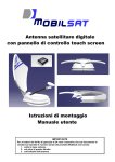
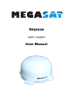
i-Sat
Mounting and usage instructions
Digital Satellite Antenna
Mounting and usage instructions
Page 1 of 12
i-Sat
Mounting and usage instructions
Summary
1.
2.
Introduction .......................................................................................................................................... 3
Safety instructions................................................................................................................................ 3
2.1.
Proper use (for the intended purpose) ............................................................................................ 3
2.2.
Safety during installation work ...................................................................................................... 3
2.3.
Proper installation and safety ......................................................................................................... 4
2.4.
Adhesive sealant ............................................................................................................................ 4
2.5.
Road Traffic Licensing Regulations .............................................................................................. 4
3. Certifications ........................................................................................................................................ 4
4. Package contents .................................................................................................................................. 5
5. Unpacking and preparation ................................................................................................................ 5
6. Mounting............................................................................................................................................... 5
6.1.
Mounting in a fixed position .......................................................................................................... 5
6.1.1.
Selection of the mounting position ........................................................................................ 5
6.1.2.
External unit space requirements ........................................................................................... 6
6.1.3.
Fixing plate mounting ............................................................................................................ 6
6.1.4.
Passing the cables through the roof ....................................................................................... 7
6.1.5.
Cable installation ................................................................................................................... 7
6.1.6.
Power supply.......................................................................................................................... 7
6.1.7.
Protection circuit .................................................................................................................... 8
6.1.8.
Connection to the satellite receiver ........................................................................................ 8
6.1.9.
Dismounting of the antenna ................................................................................................... 8
6.2.
Mounting on a mobile position ...................................................................................................... 9
7. Usage instructions ................................................................................................................................ 9
7.1.
General notes ................................................................................................................................. 9
7.2.
Power on ........................................................................................................................................ 9
7.3.
Satellite selection and search ......................................................................................................... 9
7.4.
Skew or cross-polarization tuning ............................................................................................... 10
7.5.
Manual positioning ...................................................................................................................... 10
7.6.
Power off ...................................................................................................................................... 11
7.7.
Failures or errors .......................................................................................................................... 11
7.7.1.
Generic errors....................................................................................................................... 11
7.7.2.
Reported errors..................................................................................................................... 11
7.7.3.
Reset alarm condition .......................................................................................................... 12
7.8.
System Reset ................................................................................................................................ 12
8. References ........................................................................................................................................... 12
Page 2 of 12
i-Sat
Mounting and usage instructions
1. Introduction
Read carefully and completely this manual before starting with mounting operations.
ATTENTION
The antenna and the remote control must be
mounted only by qualified personnel
In order to prevent danger during mounting operations, during normal operation and during
vehicle moving, please observe carefully the information provided in this manual.
The correct execution of the mounting operations and a correct cabling of the system are
fundamental prerequisites to guarantee conformity with related regulations.
The system is covered by CE brand and by a conformity declaration, as reported in Chapter 3.
2. Safety instructions
2.1. Proper use (for the intended purpose)
The i-Sat is designed to receive digital TV and radio programs via satellite. The turntable can be
used to receive digital TV and radio signals in the frequency range from 10.70 to 12.75GHz. Any
use other than that specified above will void the warranty or guarantee.
The following circumstances result in the loss of all warranty and liability claims towards the
manufacturer:
• Improper installation
• Use of non-specified mounting materials, which cannot guarantee the mechanical reliability
of the antenna system
• Non-permissible use, e.g. use of the planar antenna for storage
• Structural changes or interference with the components and mounting accessories in the set,
which could endanger both the mechanical and functional reliability
• Improper or forcible opening of the components
• Use of cleaners containing solvents, such as acetone, nitro-cellulose combination thinners,
degreasers, petrol, etc.
• Failure to observe installation and safety instructions in this manual
• Breaking of warranty seals
The turntable may be operated in an ambient temperature range of -10 °C to +40 °C.
Operating the system outside this range may result in malfunctions or damage to the
system.
2.2.
Safety during installation work
When carrying out installation work in locations where there is a risk of falling, take
appropriate safety precautions, e.g. use of a working platform. Make sure that the
vehicle roof is sufficiently strong and stable to carry out the installation work (risk of
damage or collapsing of roof).
Page 3 of 12
i-Sat
Mounting and usage instructions
Make sure that:
• The turntable and connected units are disconnected from the power supply
• The person carrying out the installation or repair does not suffer from vertigo and can move
around safely on the roof of the caravan or motor home
• The person carrying out the repairs is wearing sturdy and non-slip shoes
• The person carrying out the installation or repair has a secure position to stand and hold on
while working
• The roof and the climbing equipment used (e.g. ladder) are dry, clean and non-slip
• The roof can withstand the weight of the person carrying out the repairs
• Nobody should be inside the caravan/motor home underneath the antenna during
dismantling/installation
2.3. Proper installation and safety
A crucial safety factor is proper performance of installation and electrical connection work, and
the specified alignment of the turntable in the direction of travel (park position), see also
installation and connection. Follow as precisely as possible the installation conditions and steps
described. Modifications to the electrical installations in the vehicle should only be carried out by
a specialist in vehicle electrics. Do not make any unauthorized changes to the turntable.
2.4.
Adhesive sealant
The turntable is attached to the roof of the vehicle by adhesive and is secured by additional
fixing screws. Note that the curing of the adhesive sealant is temperature-dependent. It reaches
its full strength only after approximately 48 hours.
2.5. Road Traffic Licensing Regulations
The applicable regulations must be observed in respect of fixed installation of the turntable on a
vehicle which is driven on public highways.
In particular, §§ 19/2; 30 C; 32 (2) and the EC directive 74/483 EEC are applicable. Briefly, they
state that no endorsement of the vehicle documentation is required unless the antenna unit
causes the height of the laden vehicle to exceed 2mt, or the antenna unit projects beyond the
outer lateral outline of the vehicle. The maximum eligible height of 4mt (vehicle and antenna
unit) must not be exceeded.
3. Certifications
i-Sat complies with the following regulations:
Electromagnetic compatibility:
Safety:
IP graduation:
Vibrations:
EN55022, EN55024
EN12100-1, EN12100-2, EN294, EN349
EN60529
95/56/CEE
Page 4 of 12
i-Sat
Mounting and usage instructions
4. Package contents
The received package contains the following items:
- External unit with antenna
- Remote control
- Fixing plate
- Power supply cable
- Cable (4mt) for the connection with external unit
- Mounting and usage instructions
- 11mm wrench for F connectors
- Wrench for security screw
5. Unpacking and preparation
Please keep original packaging material because it will be needed in case of system return for
repair or maintenance actions. In other cases the supplier will not be responsible for damages
occurred during transport.
Please keep packaging materials out of reach of children.
6. Mounting
6.1. Mounting in a fixed position
6.1.1. Selection of the mounting position
After all doubts concerning roof stability have been eliminated and after all necessary measures
have been taken on order to assure a proper and safe assembly, position the antenna in the
planned mounting position.
Position the fixing plate, taking care that the arrow on the plate is oriented towards the front of
the caravan. Once positioned, the antenna must be oriented towards the rear of the caravan,
opposite to driving direction (see figure). All other positions will be considered as not correct. For
the final choice of the mounting position, be absolutely sure of antenna space requirements
during normal operations.
Front
Rear
Page 5 of 12
i-Sat
Mounting and usage instructions
6.1.2. External unit space requirements
Be sure that there is enough space for the folded up system and for the complete rotation of the
antenna. For a complete rotation of the antenna during the normal operation the roof of the
vehicle must be free of obstacles. The space requirements for a correct mounting of the external
unit are displayed in the following figures:
6.1.3. Fixing plate mounting
Remove the system from the fixing plate unscrewing the safety screw, rotating the antenna
about 10 degrees clockwise and raising the upper part.
ATTENTION
Position the satellite cable on the caravan roof
BEFORE pasting the plate. When pasting the cable
must be positioned in order to fill one of the four holes
in the lower part of the plate
Page 6 of 12
i-Sat
Mounting and usage instructions
The assembly plate must be glued to the roof using a commercially available sealing compound.
For the cleaning of the roof and the assembly plate use a special cleaning agent recommended
by the manufacturer of the sealing compound (e.g. SikaFlex 252, Teroson 1K-Pur). After the
sealing compound has been dried, apply the sealing compound to the bottom of the plate and
strongly apply the plate to the roof of the vehicle. If the roof of the caravan does not have the
needed consistency, fix the plate with the tapping screws, in order to obtain a stable and safe
assembly. When finished, block the antenna using the security screw. The manufacturer can not
be indicated as responsible for damages caused by an incorrect mounting.
ATTENTION
Do not close the 4 holes in the fixing plate;
they allow the passing of the cable and assure rain outflow.
6.1.4. Passing the cables through the roof
To pass the cables through the roof use, if available, the system adopted by the manufacturer of
the caravan. If no default manufacturers’ system is available, install an appropriate cable
through. Block the cable between the external unit and the cable through, in order to avoid
movements that can cause cable wear or break. Protect the cable from external weather
conditions using appropriate electrical conduits.
Check carefully the point where cable pass through the roof and the strength of the
blocking screws, if used.
a)
b)
c)
d)
6.1.5. Cable installation
Lead the cables coming from the external unit toward the remote control
Take care to cable fixing, in order to avoid oscillations - when the caravan is in motion. Such
oscillations could damage or broke internal wires; along the route to the control unit fix the
cable to the caravan walls using a commercially available cable fixing system.
If the cable is too long, coil it up near the remote control, fixing it in an appropriate way.
For installations with a cable length greater than 4mt, use high quality cables with crimped Fconnectors. The maximum allowed cable length is 10 mt
6.1.6. Power supply
Provide a sufficient power to the system. The system can be powered by a 12V or a 24V power
supply
Notes for power supply on trailers
Often trailers don’t have a stable power supply, or they don’t have a battery at all. In these cases
it’s necessary to power the system using a 220V/12V 2A voltage transformer, connected directly
to the main line. Do not use in any circumstance battery chargers, economic transformers or
non-stabilized power packs.
Once the system is powered it will perform automatically an internal auto-test. If the Led under
the ON/OFF key flashes with a red light, see the reported errors table at page 11.
Page 7 of 12
i-Sat
Mounting and usage instructions
In the following picture is displayed the electric diagram:
6.1.7. Protection circuit
IMPORTANT
In order to avoid damages by inadvertently driving with the external unit folded-up, connect the
yellow cable to the +15 vehicle line or the D+ line that carries voltage when the engine is on and
no-voltage when the engine is switched off. In this way the external unit will be automatically
retracted when the caravan engine will be switched on.
6.1.8. Connection to the satellite receiver
connect the antenna system to the satellite receiver, using the male F-connector cable coming
from the remote control. Now the system can be considered as completely mounted
6.1.9. Dismounting of the antenna
When needed (e.g. caravan parked under the trees or an obstacle present in the satellite
direction) it is possible to quickly dismount the antenna from the fixing plate, and to position it in
a point where the satellite signal can be received better.
Execute the following steps:
- Unscrew the screw that blocks the antenna to the fixing plate
- Turn the antenna 10 degrees clockwise
- Raise it taking care of do not exceed in the movement, to avoid to rip the connection
cable
- Unscrew the F connector, using the 11mm key supplied with the system
Now the antenna can be positioned where desired, taking care of placing it horizontally and to
connect it to the remote control using a good quality 75Ohm satellite cable equipped with a F
connector.
In these cases the antenna can be mounted on a tripod, available as option, equipped with a
fixing plate identical to the one mounted on the roof of the caravan.
Page 8 of 12
i-Sat
Mounting and usage instructions
6.2. Mounting on a mobile position
Execute the following steps:
- Position the antenna and the fixing plate on a plain surface, free of obstacles in the
satellite direction. For an outdoor usage is available a specific optional tripod.
- Connect the 4mt 75Ohm satellite cable, supplied with the system, using the 11mm key.
- Connect the output of the remote control to the satellite receiver.
- Connect the power supply cable (12V or 24V) to the remote control.
Now the system is ready to be used.
7. Usage instructions
7.1. General notes
When the system is powered the antenna, if
opened, will be closed automatically.
When the system is powered the led under the
ON/OFF key will flash green every 4 seconds.
This means that the system is ready to be used.
In the figure is displayed the system remote
control.
7.2. Power on
To switch on the system press the ON/OFF key. The led under the key and the one related to
the last selected satellite will become steady green.
In case the led under the ON/OFF key will become red, see the reported errors table at page 11
and execute the related instructions.
7.3. Satellite selection and search
To select another satellite press quickly the SAT key. The selected satellite is displayed by the
related green LED.
To activate the Satellite search press the SAT key for 3 seconds. During the search phase the
related satellite led flashes red; if the satellite is found the led becomes steady green. If the
system is not able to found the satellite signal the satellite led will become steady red. To stop
the search function at any time press the SAT key.
Page 9 of 12
i-Sat
Mounting and usage instructions
7.4. Skew or cross-polarization tuning
Thanks to the new advanced technologies, the area where it’s possible to receive correctly a
satellite signal is increasing more and more. All Europe dedicated TV satellites obviously point
their signals over Central Europe. When the receiver – your caravan – is outside this area, the
antenna looks at the satellite by side, from a certain “angle”. This effect is called “skew” or
"polarization” and affects the receivers located in several countries: Portugal, South Spain,
Morocco, Greece and Western Russia .
Normally the satellite system is able to compensate this effect without problems, but in some
cases a manual LNB re-positioning is needed; in practical terms, the LNB must be rotated by
some degrees. In the following table are displayed the necessary corrections of the SKEW
effect, for some European countries (approximated values)
Zone
South Spain
Portugal
Greece
West Russia
Other countries
Astra I
+15°
+15°
-12°
-15°
0°
Hotbird
+10°
+15°
-15°
-15°
0°
For positive values it is necessary to rotate the LNB CLOCKWISE, using as zero reference the
central position. For negative values the arm must be rotated COUNTERCLOCKWISE.
Execute the following steps:
- Slightly unscrew the 4 allen keys that block the waveguide
- Turn the waveguide clockwise or counter-clockwise. The maximum allowed angle is 15°
- Block again the previously unscrewed screws
For manual antenna positioning it is necessary that satellite receiver and TV set are switched on,
in order to evaluate correctly the signal strength and quality.
.
7.5. Manual positioning
When the antenna is not moving, pressing simultaneously ON/OFF and SAT keys for more than
2 seconds switches to manual positioning mode. See the following table.
1
2
3
4
5
6
ON/OFF and SAT pressed >2 sec
Operation
ON/OFF and SAT pressed >2 sec
Operation
ON/OFF and SAT pressed >2 sec
Operation
Automatic mode
manual mode
Manual positioning of elevation motor
Change motor
Manual positioning of rotation motor
Manual mode automatic mode
Automatic mode
Page 10 of 12
i-Sat
Mounting and usage instructions
.
Every time there’s a mode/controlled motor switch, the red and green leds are switched on.
Release the buttons as soon as the mode/motor is changed, to avoid system reset
7.6. Power off
To close the antenna and switch off the system press the ON/OFF key for 3 seconds. For a
better safety the system will automatically switch to stand-by status, closing the antenna dish,
when the vehicle engine is started.
7.7. Failures or errors
7.7.1. Generic errors
In the following table are displayed the most common failures/errors and the related solutions, if
applicable.
Failure
The system does not
power up
The antenna performs
the automatic satellite
search but the TV does
not display any signal
Possible solution
Check the fuse on the power line.
Check that all cables are correctly plugged in
Check that the direction toward South is free from obstacles
(building, mountains, trees, …)
Check that in your location it is not necessary to compensate the
skew angle
Check if you are in the area covered by the selected satellite
Check that all cables are correctly plugged
7.7.2. Reported errors
When iSat antenna is in pre-alarm state the ON/OFF led blinks red. The pre-alarm condition is
activated when the system detects an error that needs a slow protection.
When iSat antenna is in alarm state the ON/OFF led is steady red, and the satellite leds show
the type of error detected.
Alarm Led
1
Hotbird led red
2
Astra1 led red
3
4
5
6
7
Astra2 led red
Astra3 led red
Astra4 led red
Atlantic Bird3 led red
All leds red
Cause
Low battery (< 10V) or overload due to a excessive antenna
absorption
No communication between antenna and remote control.
Cable broken or not connected
Dish closing error
LNB broken or not powered
Elevation mechanical failure
Rotation mechanical failure
Dish closing error when engine key inserted
Notes:
In case of low battery, the error condition must be verified for at least 10 consecutive
seconds, in order to avoid false alarms due to short low voltage transitions; during these 10
seconds (pre-alarm) the ON/OFF and Hotbird led will blink red.
In the first three cases, the remote control will switch-off the antenna.
Page 11 of 12
i-Sat
Mounting and usage instructions
7.7.3. Clear alarm condition
When an alarm is detected, it’s possible to clear the alarm condition pressing the ON/OFF key
for more than 3 seconds but less than 6 seconds.
ATTENTION
If the ON/OFF key is pressed for more than 6 seconds the whole system will be reset
The functions activated by the clear alarm procedure are:
Alarm Action performed
1, 2, 3 The electronics will be reset and the antenna will act as the first power on; the first
operation will be dish closing. If the error is detected again, the alarm condition will be
activated again
4, 5, 6 The system passes in “Satellite selection” state
7
Dish closing continues
7.8. System Reset
Except of standby state, in all the remaining states it is possible to reset the whole system
pressing the ON/OFF key form more than 6 seconds. In this case the antenna is reset as the
first power on and the first operation will be the dish closing. In the following table are described
the reset operations.
ON/OFF
key
pressed
1…3Sec
3…6 Sec
> 6 Sec.
LED ON/OFF
State
Red led blinking every 0,25
sec. Green led maintains its
state
Red led blinking every 0,1 S
sec. Green led switched off
Red led steady on
Reset activation time is > 3 Sec.
ON/OFF key release reset only the alarm condition.
Reset activation time is < 3 Sec.
ON/OFF key release reset only the alarm condition.
Whole system reset
8. References
Mobiltech s.a.s.
Via Brughetti, 9/E
20030 Bovisio Masciago (MI)
Tel: (+39) 0362 – 544.928
Fax: (+39) 0362 – 576.478
Internet: www.mobiltech.it
Mailto: [email protected]
Page 12 of 12