1
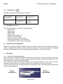
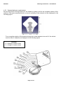
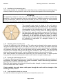
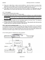
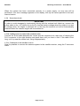
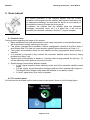
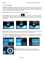
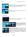
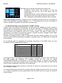
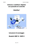
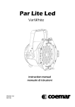
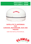
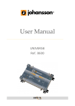
Digital satellite antenna with touch screen control panel Mounting instructions User Manual IMPORTANT To exercise the right of the 24 months warranty is mandatory that in the sales document is reported the Mobilsat serial number, that can be found: 1. under the antenna base 2. at the end of this booklet 3. on the antenna packaging Mounting Instructions – User Manual MobilSat SUMMARY 1 2 3 4 5 6 Mounting instructions ......................................................................................................................... 3 1.1 Safety instructions .......................................................................................................................... 3 1.1.1 Proper use (for the intended purpose) .................................................................................... 3 1.1.2 Safety during installation work .............................................................................................. 3 1.1.3 Proper installation and safety ................................................................................................. 4 1.1.4 Adhesive sealant .................................................................................................................... 4 1.1.5 Road Traffic Licensing Regulations ...................................................................................... 4 1.2 Certifications .................................................................................................................................. 5 1.3 Packaging content .......................................................................................................................... 5 1.4 Unpacking and preparation ............................................................................................................ 5 1.5 Mounting ........................................................................................................................................ 5 1.5.1 Selection of mounting position .............................................................................................. 5 1.5.2 External unit space requirements ........................................................................................... 6 1.5.3 Installation of the mounting plate .......................................................................................... 7 1.5.4 Mounting of the external system............................................................................................ 7 1.5.5 Passing the cables through the roof ....................................................................................... 7 1.5.6 Cable installazion inside the caravan ..................................................................................... 7 1.5.7 Power supply.......................................................................................................................... 8 1.5.8 Notes for power supply on trailers ......................................................................................... 8 1.5.9 Protection circuit .................................................................................................................... 9 1.5.10 Cabling between control and command units ........................................................................ 9 1.5.11 Connection to the satellite receiver ........................................................................................ 9 User manual ........................................................................................................................................ 10 2.1 General notes ............................................................................................................................... 10 2.2 The control panel ......................................................................................................................... 10 2.3 Basic operations ........................................................................................................................... 11 2.4 Installer menu............................................................................................................................... 12 2.5 Manual pointing (cross-polarization “SKEW” setting) ............................................................... 13 2.6 List of available satellites............................................................................................................. 14 Failures or malfunctions.................................................................................................................... 14 Technical data .................................................................................................................................... 15 Notes .................................................................................................................................................... 15 References ........................................................................................................................................... 16 Page 2 of 16 Mounting Instructions – User Manual MobilSat 1 Mounting instructions Read carefully and completely this manual at least once before starting with mounting operations. ATTENTION The antenna and the control panel must be mounted only by qualified personnel In order to prevent danger during mounting operations, during normal operation and during vehicle moving, please observe carefully the information provided in this manual. The correct execution of the mounting operations and a correct cabling of the system are fundamental prerequisites to guarantee conformity with related regulations. The system is covered by 1.2. 1.1 brand and by a conformity declaration, as reported in Capter Safety instructions 1.1.1 Proper use (for the intended purpose) The MobiSat is designed to receive digital TV and radio programs via satellite. The turntable can be used to receive digital TV and radio signals in the frequency range from 10.70 to 12.75GHz. Any use other than that specified above will void the warranty or guarantee. The following circumstances result in the loss of all warranty and liability claims towards the manufacturer: Improper installation Use of non-specified mounting materials, which cannot guarantee the mechanical reliability of the antenna system Non-permissible use, e.g. use of the planar antenna for storage Structural changes or interference with the components and mounting accessories in the set, which could endanger both the mechanical and functional reliability Improper or forcible opening of the components Use of cleaners containing solvents, such as acetone, nitro-cellulose combination thinners, petrol etc. Failure to observe installation and safety instructions in this manual The turntable may be operated in an ambient temperature range of -10 °C to +40 °C. Operating the system outside this range may result in malfunctions or damage to the system 1.1.2 Safety during installation work When carrying out installation work in locations where there is a risk of falling, take appropriate safety precautions, e.g. use of a working platform. Make sure that the Page 3 of 16 Mounting Instructions – User Manual MobilSat vehicle roof is sufficiently strong and stable to carry out the installation work (risk of damage or collapsing of roof). Make sure that: The turntable and connected units are disconnected from the power supply The person carrying out the installation or repair does not suffer from vertigo and can move around safely on the roof of the caravan or motor home The person carrying out the repairs is wearing sturdy and non-slip shoes The person carrying out the installation or repair has a secure position to stand and hold on while working The roof and the climbing equipment used (e.g. ladder) are dry, clean and non-slip The roof can withstand the weight of the person carrying out the repairs Nobody should be inside the caravan/motor home underneath the antenna during dismantling/installation 1.1.3 Proper installation and safety A crucial safety factor is proper performance of installation and electrical connection work, and the specified alignment of the turntable in the direction of travel (park position), see also installation and connection. Follow as precisely as possible the installation conditions and steps described. Modifications to the electrical installations in the vehicle should only be carried out by a specialist in vehicle electrics. Do not make any unauthorized changes to the turntable. 1.1.4 Adhesive sealant The turntable is attached to the roof of the vehicle by adhesive and is secured by additional fixing screws. Note that the curing of the adhesive sealant is temperature-dependent. It reaches its full strength only after approximately five days. 1.1.5 Road Traffic Licensing Regulations The applicable regulations must be observed in respect of fixed installation of the turntable on a vehicle which is driven on public highways. In particular, §§ 19/2; 30 C; 32 (2) and the EC directive 74/483 EEC are applicable. Briefly, they state that no endorsement of the vehicle documentation is required unless the antenna unit causes the height of the laden vehicle to exceed 2mt, or the antenna unit projects beyond the outer lateral outline of the vehicle. The maximum permissible height of 4mt (vehicle and antenna unit) must not be exceeded. Page 4 of 16 Mounting Instructions – User Manual MobilSat 1.2 Certifications MobilSat complies with the following regulations Electromagnetic compatibilità Ref rule: 2004/108/CE EN 55022:2010 EN 55024:2010 Safety Ref rule: 2006/95/CE EN 12100 EN 349 EN 13857 1.3 Packaging content The received package contains the following items: - Control Unit - External Unit - Satellite dish - Power cable - Cable set for external unit - Cable for command unit - Coaxial cable for satellite receiver - Mounting instructions / User’s manual - Fixing screws for dish and mounting plate 1.4 Unpacking and preparation Please keep original packaging material because it will be needed in case of system return for repair or maintenance actions. In other cases the supplier will not be responsible for damages occurred during transport. Please keep packaging materials out of reach of children 1.5 Mounting 1.5.1 Selection of mounting position After all doubts concerning roof stability have been eliminated and after all necessary measures have been taken on order to assure a proper and safe assembly, position the external unit and the antenna in the planned mounting position. Once positioned, both antenna and LNB must be oriented towards the rear of the caravan, opposite to driving direction. All other positions are considered not correct (see figure) For the final choice of the mounting position, be absolutely sure of antenna space requirements during normal operations. Driving direction Back of the vehicle Page 5 of 16 Mounting Instructions – User Manual MobilSat 1.5.2 External unit space requirements Be sure that there is enough space for the folded up system and for the complete rotation of the antenna. The space requirements for a correct mounting of the external unit are displayed in the following figure: For a complete rotation of the antenna during the normal operation the roof of the vehicle must be free of obstacles, as displayed in the following figure LEGEND R = Radius of rotation (mm) H = Heiglht of rotation (mm) Page 6 of 16 Mounting Instructions – User Manual MobilSat 1.5.3 Installation of the mounting plate After having decided the mounting location and after having verified antenna positioning during stand-by related to driving direction, mark on the roof the corner points of the mounting plate. ATTENTION It’s absolutely needed to mark the roof of the vehicle with a line, in order to exclude the possibility to mount the assembly plate in a wrong direction. MobilSat antenna can be mounted in only one direction; LNB must be oriented towards the rear of the vehicle. All other positions will not be considered as correct and will cause immediate guarantee expiration. The assembly plate must be glued to the roof using a commercially available sealing compound. For the cleaning of the roof and the assembly plate use a special cleaning agent recommended by the manufacturer of the sealing compound (e.g. SikaFlex, Teroson 1K-Pur). After the sealing compound has been dried, apply the sealing compound to the bottom of the plate and strongly apply the plate to the roof of the vehicle. If the roof of the caravan does not have the needed consistency, fix the plate with the tapping screws, in order to obtain a stable and safe assembly. The manufacturer can not be indicated as responsible for damages caused by an incorrect mounting. 1.5.4 Mounting of the external system Connect the cable set to the external unit. The cable can be plugged in the proper connector using the dedicated space in the lower part of the unit. After this, insert the cable in the small recess on the base of the plate and mount the external unit on the assembly plate, centering it on prisoners and fixing with the four M6 bolts and the related washers. The two M6 bolts covered by the antenna rotating base will set after installation, after moved the antenna.If the plate has been mounted correctly, now the LNB points exactly to the rear of the vehicle. After having blocked the antenna with raised arm you can mount the dish. To ensure perfect fixing use the 4 screws and the plastic washers with medium-strength threadlock glue. 1.5.5 Passing the cables through the roof To pass the cables through the roof use, if available, the system adopted by the manufacturer of the caravan. If no default manufacturers’ system is available, install a cable through (available in package) with a diameter of at least 16mm. Block the cable between the external unit and the cable through, in order to avoid movements that can cause cable wear or break. Check carefully the point where cable pass through the roof and the strength of the blocking screws, if used. 1.5.6 Cable installation inside the caravan a) Lead the cables coming from the external unit toward the control unit Page 7 of 16 Mounting Instructions – User Manual MobilSat b) Take care to cable fixing, in order to avoid oscillations - when the caravan is in motion. Such oscillations could damage or broke internal wires; along the route to the control unit fix the cable to the caravan walls using a commercially available cable fixing system. c) If the cable is too long, coil it up near the control unit, fixing it in an appropriate way. The cable between the control unit and outdoor unit should not be cut, spliced or welded. . 1.5.7 Power supply Provide a sufficient power to the system. a) The system must powered by a 12V power supply b) Connect the power cable directly to battery terminals, avoiding to use a cable that powers another utility. Often the cable section is not sufficient, to supply the original device (e.g. the television set) plus the new one. In these conditions the voltage that feeds the unit could not be sufficient. If this procedure is not applied the system could be damaged or not work in the appropriate way. c) The supply cable for lengths over 4mt. must have a section of at least 2.5mm 2. For distances of 6mt or more, cable section must be at least 4.0mm 2 d) The ideal solution is to install a new dedicated power line. The protection fuse that must be installed on this line should be between 10A and 15A. 1.5.8 Notes for power supply on trailers Often trailers don’t have a stable power supply, or they don’t have a battery at all. In these cases it’s necessary to power the system using a 220V/12V voltage transformer connected, directly to the main line. Do not use in any circumstance battery chargers, economic transformers or nonstabilized power packs. The voltage that feeds the system must be electronically stabilized and must have a nominal voltage of 13.8V, with a minimum nominal current of 6A. In the following picture is displayed the electric diagram: Page 8 of 16 Mounting Instructions – User Manual MobilSat When the system has been connected correctly to a power supply, an auto test will be performed. If an error message appears on the display, look up the cause specified in the user manual section 1.5.9 Protection circuit IMPORTANT In order to avoid damages by inadvertently driving with the external unit folded-up, connect the yellow cable to the +15 vehicle line or the D+ line that carries voltage when the engine is on and no-voltage when the engine is switched off. In this way the external unit will be automatically retracted when the caravan engine will be switched on. 1.5.10 Cabling between control and command units Connect the 4,5mt cable between the control and the command unit; take care of inserting the RJ11 connector in the right direction and push them until you here a click. If the cable is too long, coil it up near the control unit, fixing it appropriately. 1.5.11 Connection to the satellite receiver Now it’s possible to connect the antenna system to the satellite receiver, using the F-connector cable. Page 9 of 16 Mounting Instructions – User Manual MobilSat 2 User manual For proper operation of the tracking system and the correct reception of the signal from the satellite, pay attention that there are no obstructions between the dish and the south, as the majority of the satellites covering Europe are facing south. If between the caravan and the satellite there are obstacles (buildings, mountains, trees, etc.) in a direct line, it will not be possible the automatic orientation and the TV signal reception. 2.1 General notes General notes regarding the usage of the system: Base operations have been developed in such a way that power on and satellite search will be performed simply switching on the unit. The system manages three satellites. Default configuration consist of Hot Bird, Astra 1 and Atlantic Bird 3. In case you need another satellite follow instructions in Chap. 2.4. The system automatically saves the last satellite and the geographical sector setting, if selected. It is possible to interrupt in any moment the automatic satellite search function, simply pressing the “Menu” key. System goes automatically in stand-by 3 minutes after having pressed the last key. To exit the stand-by status press any the touch screen System beeper issues three different signals; A “low” signal issued for three seconds, at the end of the automatic satellite search phase A “high” signal, issued during the closing procedure of the antenna with engine on. This signal will be stopped only when the antenna is completely closed A “short” signal every time a key is pressed 2.2 The control panel All functions are activated via the touch screen control panel, shown in the following figure . Page 10 of 16 Mounting Instructions – User Manual MobilSat 2.3 Basic operations Switch on and pointing: Tap the touch screen to turn it on and press the "On / Off" button, the antenna automatically performs the search and tracking. After 3 minutes the display turns off and enters in standby mode. Pressing the menu button on the search you can be interrupted it at any time. Leaving the menu antenna resumes search Closing antenna: press the "on / off" button or turn the caravan Fine pointing: pressing the center button for more than 3 seconds (operation confirmed by a beep) the antenna rerun the fine pointing. This feature is useful when the caravan suffer some slight movement and need to adjust the pointing without having to perform a full search. Menu button: with this function you enter the main menu from which you can change user parameters. From "search mode" you can select the automatic or manual search. Auto Search, pointing to sectors: you can change the zone of automatic search based on your position. In this way the antenna will perform only the specific angles for reception in the selected zone. Standard position is "all sectors" Manual search: perform a manual search using the arrows buttons. Leaving this menu the antenna resumes automatic mode Page 11 of 16 Mounting Instructions – User Manual MobilSat Satellite selection: in this menu you can select the desired satellite from the three included in favorites. Pressing the “Exit” button antenna automatically will search the selected satellite Options menu: in this menu you can change language, adjust clock and enter the Installer menu 2.4 Installer menu Installer menu: Press the “Installer Menu” button, password “3105” and confirm by pressing "OK". type the Change the favourite satellite list among the 16 included in the list: Press the satellite you want to change. Select the new satellite and press exit to save the setting Changing parameters pointing: press "Edit" button to enter pointing configuration parameters. The display shows data entered by the manufacturer or the last setting. In case of changes of the signals transmitted by the satellite you can be updated them at any time by entering the new parameters. New parameters can be obtained from the official website of the satellite or from: www.kingofsat.net, www.satbeams.com, www.lyngsat.com, etc. Page 12 of 16 Mounting Instructions – User Manual MobilSat New data can be inserted by pressing the related box: - Frequency (Freq): enter the frequency of the new transponder and add two zeros (see figure) with the numeric keys - Symbol rate (Baud): enter the data of the new transponder and add three zeros (see figure) with the numeric keys - FEC, polarization, transmission standard: insert new data Insert new satellites (max 4): in addition to the 16 satellite included in the list it is possible to insert 4 new satellites, in position Satellite1, 2, 3, 4. This setting can be used if the system is used for reception of satellites not included in the factory list. 2.5 Manual pointing (cross-polarization “SKEW” setting) Thanks to the new advanced technologies, the area where it’s possible to receive correctly a satellite signal is increasing more and more. All Europe dedicated TV satellites obviously point their signals over Central Europe. When the receiver – your caravan – is outside this area, the antenna looks at the satellite by side, from a certain “angle”. This effect is called “skew” or "polarization” and affects the receivers located in several countries: Portugal, South Spain, Morocco, Greece, Turkey and Canary Islands Normally the satellite system is able to compensate this effect without problems, but in some cases a manual LNB re-positioning is needed; in practical terms, the LNB must be rotated by some degrees. In the following table are displayed the necessary corrections of the SKEW effect, for some European countries (approximated values) Zone South Spain Portugal Morocco, Gibilterra Canary Islands Greece Turkey, West Russia Other countries Astra I +15° +25° +20° +35° -12° -15° 0° Hotbird +10° +15° +20° +25° -20° -17° 0° For positive values it is necessary to rotate the LNB CLOCKWISE, using the “zero” indication on the LNB support as reference. For negative values the arm must be rotated COUNTERCLOCKWISE. As displayed in the following pictures, to perform this operation unscrew with an 3mm Allen wrench the two screws that fix LNB and rotate the LNB until the desired value is displayed in the hollow of the upper plate. . Pay attention to the fact that corrections of less than 10° does not necessarily have to be carried out, if reception is good. For manual positioning of the dish it is necessary that the satellite receiver and the TV are turned on, in order to assess the correct positioning of the dish itself and to try to get the maximum signal strength. Page 13 of 16 Mounting Instructions – User Manual MobilSat 2.6 List of available satellites In the following table is displayed the list of available satellites; positions 17-20 can be customized via the Installer Menu 1-5 AMOS 3W ASTRA 4.8E ASTRA 19E ASTRA 23,5E ASTRA 28E 6-10 ATLANTIC BIRD 5W ATLANTIC BIRD 8W ATLANTIC BIRD 12W EUROBIRD 9E EUROBIRD 16E 11-15 EUTELSAT 7E EUTELSAT 10E HISPASAT 30W HOTBIRD 13E THOR 1W 16-20 TURKSAT 42E SATELLITE 1 SATELLITE 2 SATELLITE 3 SATELLITE 4 3 Failures or malfunctions In case of fault the display will show the symbol and the error description The following table shows the most common causes of errors with the explanation and the possible reason/solution. Failure The system does not power up The antenna does not performs automatic satellite search Possible solution Check the fuse on the power line. Check that all cables are correctly plugged in Check that the direction toward South is free from obstacles (building, mountains, trees, …) Check that in your location it is not necessary to compensate the SKEW angle Check if you are in the area covered by the selected satellite Check that all cables are correctly plugged Check that the decoder works and is up to date The antenna performs the automatic satellite search but the TV does not display any signal Display shows ”Serial line error” Display shows ”Mechanical error” Display shows ”Engine running” Detected improper connection between control unit and touch screen display Detected mechanical malfunctions or electrical problems between control unit and outdoor unit Antenna or inhibition function due to the engine running Page 14 of 16 Mounting Instructions – User Manual MobilSat 4 Technical data Power supply: Current consumption stand-by mode: Display consumption stand-by mode: Typical consumption during sat search: MAximum consumption during sat search: Typical time for sat search: Weight: 10 - 17,5V 22mA 22mA 2,5A 4A 60 sec Kg.13 5 Notes ____________________________________________________________________________________________ ____________________________________________________________________________________________ ____________________________________________________________________________________________ ____________________________________________________________________________________________ ____________________________________________________________________________________________ ____________________________________________________________________________________________ ____________________________________________________________________________________________ ____________________________________________________________________________________________ ____________________________________________________________________________________________ ____________________________________________________________________________________________ ____________________________________________________________________________________________ ____________________________________________________________________________________________ ____________________________________________________________________________________________ ____________________________________________________________________________________________ ____________________________________________________________________________________________ ____________________________________________________________________________________________ ____________________________________________________________________________________________ ____________________________________________________________________________________________ Page 15 of 16 Mounting Instructions – User Manual MobilSat 6 References Producer Retailer stamp Mobiltech s.a.s. Via Brughetti, 9/E 20030 Bovisio Masciago (MI) Tel: (+39) 0362 – 544.928 Fax: (+39) 0362 – 576.478 Internet: www.mobiltech.it Mailto: [email protected] Serial Number label Page 16 of 16