1
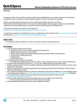
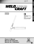
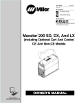
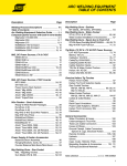
199 528C 1/2005 Processes TIG (GTAW) Welding ENGLISH OM-1603 Description Diamondback Series GTAW Torches DB1812R And DB1825R Visit our website at www.MillerWelds.com ESPAÑOL FRANÇAIS TIG Torch TABLE OF CONTENTS SECTION 1 −SAFETY PRECAUTIONS FOR GTAW TORCHES − READ BEFORE USING . . . . . . . . . . . . . . 1-1. Symbol Usage . . . . . . . . . . . . . . . . . . . . . . . . . . . . . . . . . . . . . . . . . . . . . . . . . . . . . . . . . . . . . . . . . . . . . . . . 1-2. GTAW Torch Hazards . . . . . . . . . . . . . . . . . . . . . . . . . . . . . . . . . . . . . . . . . . . . . . . . . . . . . . . . . . . . . . . . . EMF INFORMATION . . . . . . . . . . . . . . . . . . . . . . . . . . . . . . . . . . . . . . . . . . . . . . . . . . . . . . . . . . . . . . . . . . . . . . . . . . SECTION 2 − SPECIFICATIONS . . . . . . . . . . . . . . . . . . . . . . . . . . . . . . . . . . . . . . . . . . . . . . . . . . . . . . . . . . . . . . . . 2-1. Specifications . . . . . . . . . . . . . . . . . . . . . . . . . . . . . . . . . . . . . . . . . . . . . . . . . . . . . . . . . . . . . . . . . . . . . . . . 2-2. Duty Cycle . . . . . . . . . . . . . . . . . . . . . . . . . . . . . . . . . . . . . . . . . . . . . . . . . . . . . . . . . . . . . . . . . . . . . . . . . . . SECTION 3 − INSTALLATION . . . . . . . . . . . . . . . . . . . . . . . . . . . . . . . . . . . . . . . . . . . . . . . . . . . . . . . . . . . . . . . . . . 3-1. Required Torch Parts And Torch Assembly . . . . . . . . . . . . . . . . . . . . . . . . . . . . . . . . . . . . . . . . . . . . . . . . 3-2. International Style Connector Assembly . . . . . . . . . . . . . . . . . . . . . . . . . . . . . . . . . . . . . . . . . . . . . . . . . . 3-3. Connecting Torch . . . . . . . . . . . . . . . . . . . . . . . . . . . . . . . . . . . . . . . . . . . . . . . . . . . . . . . . . . . . . . . . . . . . . SECTION 4 − MAINTENANCE & TROUBLESHOOTING . . . . . . . . . . . . . . . . . . . . . . . . . . . . . . . . . . . . . . . . . . . 4-1. Routine Maintenance . . . . . . . . . . . . . . . . . . . . . . . . . . . . . . . . . . . . . . . . . . . . . . . . . . . . . . . . . . . . . . . . . . 4-2. Troubleshooting . . . . . . . . . . . . . . . . . . . . . . . . . . . . . . . . . . . . . . . . . . . . . . . . . . . . . . . . . . . . . . . . . . . . . . SECTION 5 − SELECTING AND PREPARING TUNGSTEN ELECTRODE FOR DC OR AC WELDING . . . . 5-1. Selecting Tungsten Electrode (Wear Clean gloves To Prevent Contamination Of Tungsten) . . . . . . . . 5-2. Preparing Tungsten Electrode For Welding . . . . . . . . . . . . . . . . . . . . . . . . . . . . . . . . . . . . . . . . . . . . . . . . SECTION 6 − GUIDELINES FOR TIG WELDING (GTAW) . . . . . . . . . . . . . . . . . . . . . . . . . . . . . . . . . . . . . . . . . . 6-1. Positioning The Torch . . . . . . . . . . . . . . . . . . . . . . . . . . . . . . . . . . . . . . . . . . . . . . . . . . . . . . . . . . . . . . . . . . 6-2. Torch Movement During Welding . . . . . . . . . . . . . . . . . . . . . . . . . . . . . . . . . . . . . . . . . . . . . . . . . . . . . . . . 6-3. Positioning Torch Tungsten For Various Weld Joints . . . . . . . . . . . . . . . . . . . . . . . . . . . . . . . . . . . . . . . . SECTION 7 − PARTS LIST . . . . . . . . . . . . . . . . . . . . . . . . . . . . . . . . . . . . . . . . . . . . . . . . . . . . . . . . . . . . . . . . . . . . . WARRANTY 1 1 1 2 3 3 3 4 4 4 5 7 7 7 9 9 10 10 10 11 11 12 SR6_1/00 1-1. Symbol Usage Means Warning! Watch Out! There are possible hazards with this procedure! The possible hazards are shown in the adjoining symbols. Marks a special safety message. Means NOTE; not safety related. This group of symbols means Warning! Watch Out! Possible ELECTRIC SHOCK and HOT PARTS hazards. Consult symbols and related instructions below for necessary actions to avoid the hazards. 1-2. GTAW Torch Hazards GTAW WELDING can be hazardous. PROTECT YOURSELF AND OTHERS FROM POSSIBLE SERIOUS INJURY OR DEATH. KEEP CHILDREN AWAY. PACEMAKER WEARERS KEEP AWAY UNTIL CONSULTING YOUR DOCTOR. In welding, as in most jobs, exposure to certain hazards occurs. Welding is safe when precautions are taken. The safety information given below is only a summary of the more complete safety information found in the welding power source Owner’s Manual. Read and follow all safety precautions. HAVE ALL INSTALLATION, OPERATION, MAINTENANCE, AND REPAIR WORK PERFORMED ONLY BY QUALIFIED PEOPLE. ELECTRIC SHOCK can kill. 1. 2. 3. 4. Always wear dry insulating gloves. Insulate yourself from work and ground. Do not touch live electrode or electrical parts. Repair or replace worn, damaged, or cracked torch or cable insulation. 5. Turn off welding power source before changing tungsten electrode or torch parts. 6. Keep all covers and handle securely in place. WELDING can cause fire or explosion. 1. Do not weld near flammable material. 2. Do not weld on closed containers. 3. Watch for fire; keep extinguisher nearby. HOT SURFACES can burn skin. 1. Allow torch to cool before touching. 2. Do not touch hot metal. 3. Protect hot metal from contact by others. ARC RAYS can burn eyes and skin. 1. Wear welding helmet with correct shade of filter. 2. Wear correct eye and body protection. 3. Cover exposed skin. FUMES AND GASES can be hazardous to your health. 1. Keep your head out of the fumes. 2. Ventilate area, or use breathing device. 3. Read Material Safety Data Sheets (MSDSs) and manufacturer’s instructions for material used. NOISE can damage hearing; SOME APPLICATIONS, SUCH AS PULSING, are noisy. 1. Check for noise level limits exceeding those specified by OSHA. 2. Use approved ear plugs or ear muffs if noise level is high. 3. Warn others nearby about noise hazard. BUILD UP OF GAS can injure or kill 1. Shut off shielding gas supply when not in use. 2. Always ventilate confined spaces or use approved air-supplied respirator. OM-1603 Page 1 ENGLISH SECTION 1 −SAFETY PRECAUTIONS FOR GTAW TORCHES − READ BEFORE USING EMF INFORMATION Considerations About Welding And The Effects Of Low Frequency Electric And Magnetic Fields Welding current, as it flows through welding cables, will cause electromagnetic fields. There has been and still is some concern about such fields. However, after examining more than 500 studies spanning 17 years of research, a special blue ribbon committee of the National Research Council concluded that: “The body of evidence, in the committee’s judgment, has not demonstrated that exposure to powerfrequency electric and magnetic fields is a human-health hazard.” However, studies are still going forth and evidence continues to be examined. Until the final conclusions of the research are reached, you may wish to minimize your exposure to electromagnetic fields when welding or cutting. To reduce magnetic fields in the workplace, use the following procedures: OM-1603 Page 2 1. Keep cables close together by twisting or taping them. 2. Arrange cables to one side and away from the operator. 3. Do not coil or drape cables around your body. 4. Keep welding power source and cables as far away from operator as practical. 5. Connect work clamp to workpiece as close to the weld as possible. About Pacemakers: Pacemaker wearers consult your doctor first. If cleared by your doctor, then following the above procedures is recommended. ENGLISH SECTION 2 − SPECIFICATIONS 2-1. Specifications Model DB1812R DB1825R Ampere Rating 350 Amps W/Argon Gas @ 100% Duty Cycle DCEN, ACHF Cooling Method Water Cooling Requirements 1.1 quart/minute (1.0 liter/minute) Tungsten Size .020 Thru 5/32 in (0.5 Thru 4.0 mm) Cable Options 12-1/2 ft (3.8 m) One-Piece High−Flex Dimensions 25 ft (7.6 m) One-Piece High−Flex Length: 9 in (229 mm); Handle Diameter: 1−1/8 in (29 mm); Weight: 5.8 oz (165 g) 2-2. Duty Cycle 100% Duty Cycle At 350 Amperes Using Argon Gas 0 Definition 10 Duty Cycle is percentage of 10 minutes that torch can weld at rated load without overheating. Minutes Continuous Welding sb1.5* 8/93 EXCEEDING RATED AMPERAGE can damage torch and void warranty. • Do not exceed rated amperage (see Section 2-1) OM-1603 Page 3 SECTION 3 − INSTALLATION 3-1. Required Torch Parts And Torch Assembly 7 Assembling Torch Parts 6 4 5 3 1 2 16 1 Cup 2 Collet Body 3 Heat Shield 4 Backcap Insulator 5 Collet 6 O-Ring 7 Backcap 8 Torch Body 9 Handle 10 Power Cable 11 Water Hose 8 12 Gas Hose 12 9 13 Power Cable Adapter 14 International Style Adapter 11 13 15 Water Hose For International Style Adapter Assembling Torch Body 14 10 Keep connections tight. Replace cup, heat shield, and backcap as needed. 16 Tungsten Electrode (See Section 5) Installing Tungsten 15 To adjust tungsten position, loosen backcap. Ref. 802 676 3-2. International Style Connector Assembly 1 1 3 2 1 in (26 mm) 5 4 Weld Output Cable 2 Insulating Boot 3 Sleeve Slide insulating boot onto cable; strip cable and install sleeve. 4 Connector Body 5 Setscrew Insert cable with sleeve fully into connector body, tighten setscrew, and slide insulating boot over connector. 3 Tools Needed: ST-156 496 OM-1603 Page 4 ENGLISH 3-3. Connecting Torch A. Connecting Torch When Using A Freestanding Coolant System If applicable, install high-frequency unit. 2 1 3 4 11 7 10 12 6 8 9 5 Tools Needed: 802 560 5/8, 7/8, 1-1/8 in Turn Off welding power source and cooling system power before installing torch. 1 Welding Power Source 2 Regulator/Flowmeter 3 Gas Cylinder 4 Gas Hose (Customer Supplied) Obtain correct length with 5/8-18 right-hand fittings. 5 Torch 6 Power Cable Adapter 7 Coolant Hose (Customer Supplied) Obtain correct length with 5/8-18 left-hand fittings. 8 Coolant-Out Of Torch/Power Cable (Red) Connect coolant-out of torch/power cable to power cable adapter, and connect adapter to weld output terminal. 9 Torch Gas Hose 10 Coolant-Into Torch Hose (Blue) 11 Cooling System 12 Work Clamp Connect work clamp to a clean, paint-free location on workpiece, close to weld. Use wire brush or sandpaper to clean metal at weld joint area. OM-1603 Page 5 B. Connecting Torch To A Dynastyt 300 DX Or Maxstar 300 DX TIGRunnert Unit Turn Off welding power source power before installing torch. 2 Tools Needed: 11 1 1 3 Gas Hose With 5/8-18 RightHand Fittings (Customer Supplied) Connections: 5/8, 7/8, 1-1/8 in 9 7 8 6 2 Regulator/Flowmeter 3 Gas Cylinder 4 Coolant System 5 Torch 6 Coolant-Into Torch Hose (Blue) 7 Torch Gas Hose 8 Coolant-Out Of Torch/Power Cable (Red) 9 International Style Adapter Connect coolant-out of torch/power cable to power cable adapter, and connect adapter to weld output terminal. 5 4 10 Work Clamp Connect work clamp to a clean, paintfree location on workpiece, close to weld. Use wire brush or sandpaper to clean metal at weld joint area. 10 11 Welding Power Source 12 Foot Control 12 803 311 C. Connecting Torch To A Syncrowave 250 DX Or 350 LX TIGRunnert Unit Turn Off welding power source power before installing torch. Tools Needed: 3 1 1 2 Gas Hose With 5/8-18 Right-Hand Fittings (Customer Supplied) Connections: 5/8, 7/8, 1-1/8 in 4 5 2 Regulator/Flowmeter 3 Power Source 4 Gas Cylinder 5 Coolant System 6 Coolant Hose (Supplied With TIGRunner) 7 Power Cable Adapter 8 Torch 9 Coolant-Into Torch Hose (Blue) 10 Coolant-Out Of Torch/Power Cable (Red) Connect torch coolant-out of torch/power cable to power cable adapter, and connect adapter to weld output terminal. 8 11 Torch Gas Hose 9 6 Connect work clamp to a clean, paintfree location on workpiece, close to weld. 7 12 10 12 Work Clamp 11 Use wire brush or sandpaper to clean metal at weld joint area. 13 Foot Control 13 803 311 OM-1603 Page 6 4-1. Routine Maintenance Disconnect torch before maintaining. 40 Hours Clean and tighten weld terminals. Repair or replace cracked weld cable. Replace unreadable labels. Replace cracked parts Torch Body Torch Cable 4-2. Troubleshooting NOTE Before using troubleshooting table, check selection and preparation of tungsten electrode according to Section 5. Trouble Remedy Arc will not start. High frequency present Check cable and work connections. Be sure weld circuit is complete (see Section 3-3). and visible at the torch. Check and be sure shielding gas is present. Lack of high frequency; difficulty in es- Select proper size and type tungsten. Properly prepare tungsten according to Section 5. tablishing arc. Check cables and torch for cracks or bad connections. Be sure that torch cables are not close to any grounded metal. Repair or replace necessary parts. Check torch consumables. Be sure collet and collet body are correctly installed and tightened (see Section 3-1). Check welding power source High Frequency control, and if necessary, check and adjust spark gaps. Torch gas valve not working properly (if Have Factory Authorized Service Station/Service Distributor check valve. applicable). No shielding gas flow from torch. Be sure valves on gas supply are open. Check cable for kinks or blockage. Check and tighten all gas supply fittings. Check cables and torch for cracked insulation or bad connections. Repair or replace (see Section 4-1). Tungsten electrode oxidizing and not re- Shield weld zone from drafts. maining bright after conclusion of weld. Increase postflow time. Increase gas flow rate. Check manufacture’s recommendations. Check and tighten all gas fittings. Check gas valve and flow meter/regulator. Select proper size and type tungsten. Properly prepare tungsten (see Section 5). Excessive tungsten electrode con- Select proper size and type tungsten. Properly prepare tungsten according to Section 5. sumption. Check polarity setting on welding power source (see welding power source Owner’s manual). Check for proper gas flow rate. Check manufacture’s recommendations. If torch is water cooled, check torch and cables for water leaks. Repair or replace if necessary (see Section 4-1). OM-1603 Page 7 ENGLISH SECTION 4 − MAINTENANCE & TROUBLESHOOTING Trouble Wandering arc Remedy Shield weld zone from drafts. Reduce gas flow rate. Select proper size and type tungsten. Properly prepare tungsten according to Section 5. When using AC, check welding power source High Frequency control setting, and increase setting if necessary. Yellow powder or smoke on cup. Use proper type shielding gas. Check for proper gas flow rate. Check manufacture’s recommendations. Increase postflow time. Check torch cup size. Match cup size to joint being welded. Erratic arc When using DC, check polarity, and/or polarity of welding cables. When using AC, check welding power source High Frequency control setting, and be sure it is operating continuously. Select proper size and type tungsten. Properly prepare tungsten according to Section 5. Use proper arc length. Arc length may be too long or too short. Make sure base material is clean and free of contaminates. When using AC, slow travel speed can cause erratic arc. Adjust travel speed. Porosity in weld. Check for proper gas flow rate. Check manufacture’s recommendations. Check and tighten gas fittings. Make sure base material and filler material is clean and free of contaminates. Check for impurities and moisture in gas lines. Purge if necessary. If torch is water cooled, check torch and cables for water leaks. Repair or replace if necessary (see Section 4-1). OM-1603 Page 8 ac/dc_gtaw 2/2004 Whenever possible and practical, use DC weld output instead of AC weld output. 5-1. Selecting Tungsten Electrode (Wear Clean gloves To Prevent Contamination Of Tungsten ) Amperage Range - Gas Type♦ - Polarity Electrode Diameter DC − Argon − Electrode Negative/Straight Polarity DC − Argon − Electrode Positive/Reverse Polarity AC − Argon AC − Argon − .010” Up to 25 * Up to 20 Up to 15 .020” 15-40 * 15-35 5-20 Balanced Wave 2% Ceria (Orange Band), 1.5% Lanthanum (Gray Band), Or 2% Thorium (Red Band) Alloy Tungstens .040” 25-85 * 20-80 20-60 1/16” 50-160 10-20 50-150 60-120 3/32” 135-235 15-30 130-250 100-180 1/8” 250-400 25-40 225-360 160-250 5/32” 400-500 40-55 300-450 200-320 3/16” 500-750 55-80 400-500 290-390 1/4” 750-1000 80-125 600-800 340-525 .010” Up to 15 * Up to 15 Up to 10 .020” 5-20 * 5-20 10-20 .040” 15-80 * 10-60 20-30 1/16” 70-150 10-20 50-100 30-80 3/32” 125-225 15-30 100-160 60-130 1/8” 225-360 25-40 150-210 100-180 5/32” 360-450 40-55 200-275 160-240 3/16” 450-720 55-80 250-350 190-300 1/4” 720-950 80-125 325-450 250-400 .010” * * Up to 20 Up to 15 .020” * * 15-35 5-20 .040” * * 20-80 20-60 1/16” * * 50-150 60-120 3/32” * * 130-250 100-180 1/8” * * 225-360 160-250 5/32” * * 300-450 200-320 3/16” * * 400-550 290-390 1/4” * * 600-800 340-525 Pure Tungsten (Green Band) Zirconium Alloyed Tungsten (Brown Band) ♦Typical argon shielding gas flow rates are 15 to 35 cfh (cubic feet per hour). *Not Recommended. Figures listed are a guide and are a composite of recommendations from American Welding Society (AWS) and electrode manufacturers. OM-1603 Page 9 ENGLISH SECTION 5 − SELECTING AND PREPARING TUNGSTEN ELECTRODE FOR DC OR AC WELDING 5-2. Preparing Tungsten Electrode For Welding Grinding the tungsten electrode produces dust and flying sparks which can cause injury and start fires. Use local exhaust (forced ventilation) at the grinder or wear an approved respirator. Read MSDS for safety information. Consider using tungsten containing ceria, lanthana, or yttria instead of thoria. Grinding dust from thoriated electrodes contains low-level radioactive material. Properly dispose of grinder dust in an environmentally safe way. Wear proper face, hand, and body protection. Keep flammables away. A. Preparing Tungsten For DC Electrode Negative (DCEN) Welding Or AC Welding With Inverter Machines 2-1/2 Times Electrode Diameter Radial Grinding Causes Wandering Arc 1 3 2 1 2 3 Tungsten Electrode Flat Diameter of this flat determines amperage capacity. 4 Wrong Tungsten Preparation Grinding Wheel Grind end of tungsten on fine grit, hard abrasive wheel before welding. Do not use wheel for other jobs or tungsten can become contaminated causing lower weld quality. Ideal Tungsten Preparation − Stable Arc 4 Straight Ground Grind lengthwise, not radial. B. Preparing Tungsten For Conventional AC Welding 1 − 1-1/2 Times Electrode Diameter 1 2 1 2 Tungsten Electrode Balled End Ball end of tungsten by applying AC amperage recommended for a given electrode diameter (see Section 5-1). Let ball on end of the tungsten take its own shape. SECTION 6 − GUIDELINES FOR TIG WELDING (GTAW) 6-1. Positioning The Torch Weld current can damage electronic parts in vehicles. Disconnect both battery cables before welding on a vehicle. Place work clamp as close to the weld as possible. For additional information, see your distributor for a handbook on the 3 Gas Tungsten Arc Welding (GTAW) process. 2 1 Workpiece Make sure workpiece is clean before welding. 4 2 Work Clamp Place as close to the weld as possible. 1 4 3 4 5 6 90° 10−15° Select and prepare tungsten according to Sections 5-1 and 5-2. 5 6 10−25° 5 6 Guidelines: The inside diameter of the gas cup should be at least three times the tungsten diameter to provide adequate shielding gas coverage. (For example, if tungsten is 1/16 in diameter, gas cup should be a minimum of 3/16 in diameter. Tungsten extension is the distance the tungsten extends out gas cup of torch. 1/16 in The tungsten extension should be no greater than the inside diameter of the gas cup. 3/16 in Arc length is the distance from the tungsten to the workpiece. Bottom View Of Gas Cup OM-1603 Page 10 Torch Filler Rod (If Applicable) Gas Cup Tungsten Electrode Ref. ST-161 892 ENGLISH 6-2. Torch Movement During Welding Tungsten Without Filler Rod 75° Welding direction Form pool Tilt torch Move torch to front of pool. Repeat process. Tungsten With Filler Rod 75° Welding direction Form pool 15° Tilt torch Remove rod Add filler metal Move torch to front of pool. Repeat process. ST-162 002-B 6-3. Positioning Torch Tungsten For Various Weld Joints “T” Joint Butt Weld And Stringer Bead 20° 90° 70° 75° 20° 10° 15° Corner Joint Lap Joint 20-40° 90° 75° 75° 15° 15° 30° ST-162 003 / S-0792 OM-1603 Page 11 SECTION 7 − PARTS LIST 1 3 6 7 5 4 2 10 8 11 14 15 9 12 18 13 17 19 20 16 21 Ref. 802 676-A Figure 7-1. Complete Torch Assembly OM-1603 Page 12 Item No. Stock No. Model No. Quantity Model Description DB1812R DB1825R Figure 7-1. Complete Torch Assembly . . 1 . . . . . . 57Y02 . . . . . . . . . . . . . . . BACK CAP, long (consisting of) . . . . . . . . . . . . . . . . . . . . . . . . . . . . . . 1 . . . . . . 2 . . . . . ♦57Y04 . . . . . . . . . . . . . . . BACK CAP, button . . . . . . . . . . . . . . . . . . . . . . . . . . . . . . . . . . . . . . . . . 1 . . . . . . . . . . . . . 199 591 . . . . . . . . . . . . . . . . O-Ring . . . . . . . . . . . . . . . . . . . . . . . . . . . . . . . . . . . . . . . . . . . . . . . . . . 1 . . . . . . 3 . . . . . . . . 18-7 . . . . . . . . . . . . . . . INSULATOR, back cap . . . . . . . . . . . . . . . . . . . . . . . . . . . . . . . . . . . . . . 1 . . . . . . 4 . . . . . . . DB18 . . . . . . . . . . . . . . . TORCH BODY . . . . . . . . . . . . . . . . . . . . . . . . . . . . . . . . . . . . . . . . . . . . . 1 . . . . . . 5 . . . . . . . 18CG . . . . . . . . . . . . . . . INSULATOR, cup . . . . . . . . . . . . . . . . . . . . . . . . . . . . . . . . . . . . . . . . . . 1 . . . . . . 6 . . . . . ♦54N01 . . . . . . . . . . . . . . . GAS LENS INSULATOR, medium . . . . . . . . . . . . . . . . . . . . . . . . . . . . 1 . . . . . . 7 . . . . . ♦54N63 . . . . . . . . . . . . . . . GAS LENS INSULATOR, large . . . . . . . . . . . . . . . . . . . . . . . . . . . . . . . 1 . . . . . . 8 . . . . . . 10N24 . . . . . . . . . . . . . . . COLLET, 3/32 . . . . . . . . . . . . . . . . . . . . . . . . . . . . . . . . . . . . . . . . . . . . . 1 . . . . . . 8 . . . . . ♦10N21 . . . . . . . . . . . . . . . COLLET, .020 . . . . . . . . . . . . . . . . . . . . . . . . . . . . . . . . . . . . . . . . . . . . . 1 . . . . . . 8 . . . . . ♦10N22 . . . . . . . . . . . . . . . COLLET, .040 . . . . . . . . . . . . . . . . . . . . . . . . . . . . . . . . . . . . . . . . . . . . . 1 . . . . . . 8 . . . . . ♦10N23 . . . . . . . . . . . . . . . COLLET, 1/16 . . . . . . . . . . . . . . . . . . . . . . . . . . . . . . . . . . . . . . . . . . . . . 1 . . . . . . 8 . . . . . ♦10N25 . . . . . . . . . . . . . . . COLLET, 1/8 . . . . . . . . . . . . . . . . . . . . . . . . . . . . . . . . . . . . . . . . . . . . . . 1 . . . . . . 8 . . . . . ♦54N20 . . . . . . . . . . . . . . . COLLET, 5/32 . . . . . . . . . . . . . . . . . . . . . . . . . . . . . . . . . . . . . . . . . . . . . 1 . . . . . . 9 . . . . . . 10N32 . . . . . . . . . . . . . . . COLLET BODY, 3/32 . . . . . . . . . . . . . . . . . . . . . . . . . . . . . . . . . . . . . . . 1 . . . . . . 9 . . . . . ♦10N29 . . . . . . . . . . . . . . . COLLET BODY, .020 . . . . . . . . . . . . . . . . . . . . . . . . . . . . . . . . . . . . . . . 1 . . . . . . 9 . . . . . ♦10N28 . . . . . . . . . . . . . . . COLLET BODY, 1/8 . . . . . . . . . . . . . . . . . . . . . . . . . . . . . . . . . . . . . . . . 1 . . . . . . 9 . . . . . ♦10N30 . . . . . . . . . . . . . . . COLLET BODY, .040 . . . . . . . . . . . . . . . . . . . . . . . . . . . . . . . . . . . . . . . 1 . . . . . . 9 . . . . . ♦10N31 . . . . . . . . . . . . . . . COLLET BODY, 1/16 . . . . . . . . . . . . . . . . . . . . . . . . . . . . . . . . . . . . . . . 1 . . . . . . 9 . . . ♦406 488 . . . . . . . . . . . . . . . COLLET BODY, 5/32 . . . . . . . . . . . . . . . . . . . . . . . . . . . . . . . . . . . . . . . 1 . . . . . 10 . . . . ♦45V25 . . . . . . . . . . . . . . . GAS LENS, medium . . . . . . . . . . . . . . . . . . . . . . . . . . . . . . . . . . . . . . . . 1 . . . . . 10 . . . . ♦45V26 . . . . . . . . . . . . . . . GAS LENS, medium . . . . . . . . . . . . . . . . . . . . . . . . . . . . . . . . . . . . . . . . 1 . . . . . 10 . . . . ♦45V27 . . . . . . . . . . . . . . . GAS LENS, medium . . . . . . . . . . . . . . . . . . . . . . . . . . . . . . . . . . . . . . . . 1 . . . . . 10 . . . . ♦45V24 . . . . . . . . . . . . . . . GAS LENS, medium . . . . . . . . . . . . . . . . . . . . . . . . . . . . . . . . . . . . . . . . 1 . . . . . 10 . . . . ♦45V28 . . . . . . . . . . . . . . . GAS LENS, medium . . . . . . . . . . . . . . . . . . . . . . . . . . . . . . . . . . . . . . . . 1 . . . . . 10 . . . . ♦45V29 . . . . . . . . . . . . . . . GAS LENS, medium . . . . . . . . . . . . . . . . . . . . . . . . . . . . . . . . . . . . . . . . 1 . . . . . 11 . ♦45V0204 . . . . . . . . . . . . . . . GAS LENS, large . . . . . . . . . . . . . . . . . . . . . . . . . . . . . . . . . . . . . . . . . . 1 . . . . . 11 . . . ♦45V116 . . . . . . . . . . . . . . . GAS LENS, large . . . . . . . . . . . . . . . . . . . . . . . . . . . . . . . . . . . . . . . . . . 1 . . . . . 11 . . . . ♦45V64 . . . . . . . . . . . . . . . GAS LENS, large . . . . . . . . . . . . . . . . . . . . . . . . . . . . . . . . . . . . . . . . . . 1 . . . . . 11 . . . ♦995795 . . . . . . . . . . . . . . . GAS LENS, large . . . . . . . . . . . . . . . . . . . . . . . . . . . . . . . . . . . . . . . . . . 1 . . . . . 11 . . . . ♦45V63 . . . . . . . . . . . . . . . GAS LENS, large . . . . . . . . . . . . . . . . . . . . . . . . . . . . . . . . . . . . . . . . . . 1 . . . . . 12 . . . . . 10N47 . . . . . . . . . . . . . . . NOZZEL, #7 alumina . . . . . . . . . . . . . . . . . . . . . . . . . . . . . . . . . . . . . . . 1 . . . . . 12 . . . . ♦10N44 . . . . . . . . . . . . . . . NOZZEL, #12 alumina . . . . . . . . . . . . . . . . . . . . . . . . . . . . . . . . . . . . . . 1 . . . . . 12 . . . . ♦10N45 . . . . . . . . . . . . . . . NOZZEL, #10 alumina . . . . . . . . . . . . . . . . . . . . . . . . . . . . . . . . . . . . . . 1 . . . . . 12 . . . . ♦10N46 . . . . . . . . . . . . . . . NOZZEL, #8 alumina . . . . . . . . . . . . . . . . . . . . . . . . . . . . . . . . . . . . . . . 1 . . . . . 12 . . . . ♦10N48 . . . . . . . . . . . . . . . NOZZEL, #6 alumina . . . . . . . . . . . . . . . . . . . . . . . . . . . . . . . . . . . . . . . 1 . . . . . 12 . . . . ♦10N49 . . . . . . . . . . . . . . . NOZZEL, #5 alumina . . . . . . . . . . . . . . . . . . . . . . . . . . . . . . . . . . . . . . . 1 . . . . . 12 . . . . ♦10N50 . . . . . . . . . . . . . . . NOZZEL, #4 alumina . . . . . . . . . . . . . . . . . . . . . . . . . . . . . . . . . . . . . . . 1 . . . . . 13 . . . . ♦54N14 . . . . . . . . . . . . . . . NOZZEL, medium alumina . . . . . . . . . . . . . . . . . . . . . . . . . . . . . . . . . . 1 . . . . . 13 . . . . ♦54N15 . . . . . . . . . . . . . . . NOZZEL, medium alumina . . . . . . . . . . . . . . . . . . . . . . . . . . . . . . . . . . 1 . . . . . 13 . . . . ♦54N16 . . . . . . . . . . . . . . . NOZZEL, medium alumina . . . . . . . . . . . . . . . . . . . . . . . . . . . . . . . . . . 1 . . . . . 13 . . . . ♦54N17 . . . . . . . . . . . . . . . NOZZEL, medium alumina . . . . . . . . . . . . . . . . . . . . . . . . . . . . . . . . . . 1 . . . . . 13 . . . . ♦54N18 . . . . . . . . . . . . . . . NOZZEL, medium alumina . . . . . . . . . . . . . . . . . . . . . . . . . . . . . . . . . . 1 . . . . . 14 . . . . ♦57N74 . . . . . . . . . . . . . . . NOZZEL, large alumina . . . . . . . . . . . . . . . . . . . . . . . . . . . . . . . . . . . . . 1 . . . . . 14 . . . . ♦57N75 . . . . . . . . . . . . . . . NOZZEL, large alumina . . . . . . . . . . . . . . . . . . . . . . . . . . . . . . . . . . . . . 1 . . . . . 14 . . . . ♦53N87 . . . . . . . . . . . . . . . NOZZEL, large alumina . . . . . . . . . . . . . . . . . . . . . . . . . . . . . . . . . . . . . 1 . . . . . 14 . . . . ♦53N88 . . . . . . . . . . . . . . . NOZZEL, large alumina . . . . . . . . . . . . . . . . . . . . . . . . . . . . . . . . . . . . . 1 . . . . . 15 . . . . H200M . . . . . . . . . . . . . . . HANDLE . . . . . . . . . . . . . . . . . . . . . . . . . . . . . . . . . . . . . . . . . . . . . . . . . . 1 . . . . . 16 . . . . 41V29R . . . . . . . . . . . . . . . CABLE, power 25 ft . . . . . . . . . . . . . . . . . . . . . . . . . . . . . . . . . . . . . . . . . . . . . . . . 16 . . . . 40V64R . . . . . . . . . . . . . . . CABLE, power 12 ft . . . . . . . . . . . . . . . . . . . . . . . . . . . . . . . . . . . . . . . . 1 . 17 . . . . 41V32R . . . . . . . . . . . . . . . HOSE, water 25 ft . . . . . . . . . . . . . . . . . . . . . . . . . . . . . . . . . . . . . . . . . . . . . . . . . . 17 . . . . 40V74R . . . . . . . . . . . . . . . HOSE, water 12 ft . . . . . . . . . . . . . . . . . . . . . . . . . . . . . . . . . . . . . . . . . . 1 . 18 . . . . 41V30R . . . . . . . . . . . . . . . HOSE, gas 25 ft . . . . . . . . . . . . . . . . . . . . . . . . . . . . . . . . . . . . . . . . . . . . . . . . . . . 18 . . . . 40V75R . . . . . . . . . . . . . . . HOSE, gas 12 ft . . . . . . . . . . . . . . . . . . . . . . . . . . . . . . . . . . . . . . . . . . . 1 . 19 . . . . ♦45V11 . . . . . . . . . . . . . . . ADAPTER, power cable (included in DTP kit) . . . . . . . . . . . . . . . . . . . . . . . . . . 20 . . ♦190 219 . . . . . . . . . . . . . . . ADAPTER, international style (water hose included) . . . . . . . . . . . . 1 . . . . 1 1 1 1 1 1 1 1 1 1 1 1 1 1 1 1 1 1 1 1 1 1 1 1 1 1 1 1 1 1 1 1 1 1 1 1 1 1 1 1 1 1 1 1 1 1 1 1 1 1 1 1 1 OM-1603 Page 13 Item No. Stock No. Model No. Quantity Model Description DB1812R DB1825R Figure 7-1. Complete Torch Assembly (continued) . 21 . . ♦198 314 . . . . . . . . . . . . . . . HOSE, water side adapter international style (included w/190 219) 1 . . . . . . . . . . . . . ♦AK3C . . . . . . . . . . . . . . . ACCESSORY KIT (included in DTP kit) . . . . . . . . . . . . . . . . . . . . . . . . . . . . . . . . . . . ♦CC322HD . . . . . . . . . . . . . . . CABLE COVER, 22 ft (not shown) . . . . . ♦CC310HD . . . . . . . . . . . . . . . CABLE COVER, 10 ft (not shown) . . . . . . . . ♦194738 . . . . . . . . . . . . . . . REGULATOR (included in DTP kit) . . . . . . . . . . . . . . . . . . . . . . . . . . . . . . . . . . . . . . . . . ♦198 319 . . . . . . . . . . . . . . . CLAMP, ground 15ft (included in DTP kit) . . . . . . . . . . . . . . . . . . . . . . . . . . . . . . . . . . . . ♦198 317 . . . . . . . . . . . . . . . HOSE, gas 12 ft (included in DTP kit) . . . . . . . . . . . . . . . . . . . . . . . . . . . . . . . . . . . . . . . ♦198 316 . . . . . . . . . . . . . . . HOSE, gas 3 ft (included in DTP kit) . . . . . . . . . . . . . . . . . . . . . . . . . . . . . . . . . . . . . . . . ♦198 315 . . . . . . . . . . . . . . . HOSE, water 6 ft (included in DTP kit) . . . . . . . . . . . . . . . . . . . . . . . . . . . . . . . ♦OPTIONAL BE SURE TO PROVIDE MODEL AND STYLE NUMBER WHEN ORDERING REPLACEMENT PARTS. OM-1603 Page 14 1 1 1 1 1 1 1 ENGLISH Notes Notes This limited warranty supersedes all previous Miller warranties and is exclusive with no other guarantees or warranties expressed or implied. Warranty Questions? Call 1-800-4-A-MILLER for your local Miller distributor. Your distributor also gives you ... Service You always get the fast, reliable response you need. Most replacement parts can be in your hands in 24 hours. Support Need fast answers to the tough welding questions? Contact your distributor. The expertise of the distributor and Miller is there to help you, every step of the way. * LIMITED WARRANTY − Subject to the terms and conditions below, Miller Electric Mfg. Co., Appleton, Wisconsin, warrants to its original retail purchaser that new Miller equipment sold after the effective date of this limited warranty is free of defects in material and workmanship at the time it is shipped by Miller. THIS WARRANTY IS EXPRESSLY IN LIEU OF ALL OTHER WARRANTIES, EXPRESS OR IMPLIED, INCLUDING THE WARRANTIES OF MERCHANTABILITY AND FITNESS. Induction Heating Coils and Blankets * APT & SAF Model Plasma Cutting Torches * Remote Controls * Accessory Kits * Replacement Parts (No labor) * Spoolmate Spoolguns * Canvas Covers Within the warranty periods listed below, Miller will repair or replace any warranted parts or components that fail due to such defects in material or workmanship. Miller must be notified in writing within thirty (30) days of such defect or failure, at which time Miller will provide instructions on the warranty claim procedures to be followed. Miller’s True Blue Limited Warranty shall not apply to: 1. Miller shall honor warranty claims on warranted equipment listed below in the event of such a failure within the warranty time periods. All warranty time periods start on the date that the equipment was delivered to the original retail purchaser, or one year after the equipment is sent to a North American distributor or eighteen months after the equipment is sent to an International distributor. Consumable components; such as contact tips, cutting nozzles, contactors, brushes, slip rings, relays or parts that fail due to normal wear. (Exception: brushes, slip rings, and relays are covered on Bobcat, Trailblazer, and Legend models.) 2. Items furnished by Miller, but manufactured by others, such as engines or trade accessories. These items are covered by the manufacturer’s warranty, if any. 3. Equipment that has been modified by any party other than Miller, or equipment that has been improperly installed, improperly operated or misused based upon industry standards, or equipment which has not had reasonable and necessary maintenance, or equipment which has been used for operation outside of the specifications for the equipment. 1. 5 Years Parts — 3 Years Labor * * 2. 3 Years — Parts and Labor * * * * 3. Original main power rectifiers Inverters (input and output rectifiers only) Transformer/Rectifier Power Sources Plasma Arc Cutting Power Sources Semi-Automatic and Automatic Wire Feeders Inverter Power Sources (Unless Otherwise Stated) * Water Coolant Systems (Integrated) * * * Intellitig Maxstar 150 Engine Driven Welding Generators (NOTE: Engines are warranted separately by the engine manufacturer.) 1 Year — Parts and Labor Unless Specified * * * * * * * * * * * * * * * * * * * DS-2 Wire Feeder Motor Driven Guns (w/exception of Spoolmate Spoolguns) Process Controllers Positioners and Controllers Automatic Motion Devices RFCS Foot Controls Induction Heating Power Sources and Coolers Water Coolant Systems (Non-Integrated) Flowgauge and Flowmeter Regulators (No Labor) HF Units Grids Maxstar 85, 140 Spot Welders Load Banks Arc Stud Power Sources & Arc Stud Guns Racks Running Gear/Trailers Plasma Cutting Torches (except APT & SAF Models) Field Options (NOTE: Field options are covered under True Blue for the remaining warranty period of the product they are installed in, or for a minimum of one year — whichever is greater.) 4. 6 Months — Batteries 5. 90 Days — Parts * MIG Guns/TIG Torches MILLER PRODUCTS ARE INTENDED FOR PURCHASE AND USE BY COMMERCIAL/INDUSTRIAL USERS AND PERSONS TRAINED AND EXPERIENCED IN THE USE AND MAINTENANCE OF WELDING EQUIPMENT. In the event of a warranty claim covered by this warranty, the exclusive remedies shall be, at Miller’s option: (1) repair; or (2) replacement; or, where authorized in writing by Miller in appropriate cases, (3) the reasonable cost of repair or replacement at an authorized Miller service station; or (4) payment of or credit for the purchase price (less reasonable depreciation based upon actual use) upon return of the goods at customer’s risk and expense. Miller’s option of repair or replacement will be F.O.B., Factory at Appleton, Wisconsin, or F.O.B. at a Miller authorized service facility as determined by Miller. Therefore no compensation or reimbursement for transportation costs of any kind will be allowed. TO THE EXTENT PERMITTED BY LAW, THE REMEDIES PROVIDED HEREIN ARE THE SOLE AND EXCLUSIVE REMEDIES. IN NO EVENT SHALL MILLER BE LIABLE FOR DIRECT, INDIRECT, SPECIAL, INCIDENTAL OR CONSEQUENTIAL DAMAGES (INCLUDING LOSS OF PROFIT), WHETHER BASED ON CONTRACT, TORT OR ANY OTHER LEGAL THEORY. ANY EXPRESS WARRANTY NOT PROVIDED HEREIN AND ANY IMPLIED WARRANTY, GUARANTY OR REPRESENTATION AS TO PERFORMANCE, AND ANY REMEDY FOR BREACH OF CONTRACT TORT OR ANY OTHER LEGAL THEORY WHICH, BUT FOR THIS PROVISION, MIGHT ARISE BY IMPLICATION, OPERATION OF LAW, CUSTOM OF TRADE OR COURSE OF DEALING, INCLUDING ANY IMPLIED WARRANTY OF MERCHANTABILITY OR FITNESS FOR PARTICULAR PURPOSE, WITH RESPECT TO ANY AND ALL EQUIPMENT FURNISHED BY MILLER IS EXCLUDED AND DISCLAIMED BY MILLER. Some states in the U.S.A. do not allow limitations of how long an implied warranty lasts, or the exclusion of incidental, indirect, special or consequential damages, so the above limitation or exclusion may not apply to you. This warranty provides specific legal rights, and other rights may be available, but may vary from state to state. In Canada, legislation in some provinces provides for certain additional warranties or remedies other than as stated herein, and to the extent that they may not be waived, the limitations and exclusions set out above may not apply. This Limited Warranty provides specific legal rights, and other rights may be available, but may vary from province to province. miller_warr 1/05 ENGLISH Effective January 1, 2005 (Equipment with a serial number preface of “LF” or newer) Owner’s Record Please complete and retain with your personal records. Model Name Serial/Style Number Purchase Date (Date which equipment was delivered to original customer.) Distributor Address City State Zip For Service Contact a DISTRIBUTOR or SERVICE AGENCY near you. Always provide Model Name and Serial/Style Number. Contact your Distributor for: Welding Supplies and Consumables Options and Accessories Personal Safety Equipment Service and Repair Miller Electric Mfg. Co. An Illinois Tool Works Company 1635 West Spencer Street Appleton, WI 54914 USA Replacement Parts Training (Schools, Videos, Books) International Headquarters−USA USA Phone: 920-735-4505 Auto-Attended USA & Canada FAX: 920-735-4134 International FAX: 920-735-4125 Technical Manuals (Servicing Information and Parts) Circuit Diagrams European Headquarters − United Kingdom Phone: 44 (0) 1204-593493 FAX: 44 (0) 1204-598066 Welding Process Handbooks To locate a Distributor or Service Agency visit www.millerwelds.com or call 1-800-4-A-Miller Contact the Delivering Carrier to: www.MillerWelds.com File a claim for loss or damage during shipment. For assistance in filing or settling claims, contact your distributor and/or equipment manufacturer’s Transportation Department. PRINTED IN USA 2005 Miller Electric Mfg. Co. 1/05