1
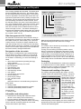
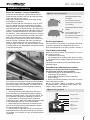
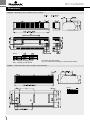
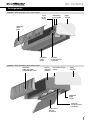
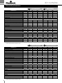
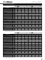
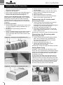
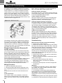
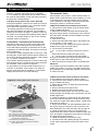
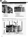
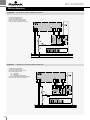
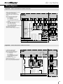
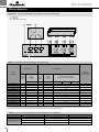
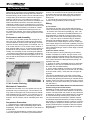
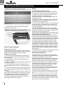
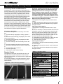
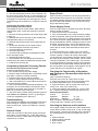
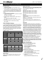
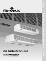
INSTALLATION AND OPERATING INSTRUCTIONS Air curtains C1, D2 04/2013 Air curtains Contents Application, Operating Conditions and Construction..............................................................3 Designations, storage, shipping.................................................................................................4 Installation.....................................................................................................................................5 Dimensions...................................................................................................................................6 Arrangement.................................................................................................................................6 Technical parameters...................................................................................................................8 Heating outputs of water exchangers......................................................................................10 Mounting.....................................................................................................................................11 Electrical connection.................................................................................................................12 Putting into operation................................................................................................................13 Mounting of accessories...........................................................................................................14 Controllers and room thermostats...........................................................................................16 Connection diagrams.................................................................................................................17 Chaining of curtains...................................................................................................................22 Operating and maintenance instructions.................................................................................23 Maintenance, operation checks................................................................................................24 Troubleshooting.........................................................................................................................25 Spare parts, service and disposal............................................................................................26 The up to date version of this document is available at our website: www.remak.eu 2 Air curtains Application, Operating Conditions and Construction Information from the manufacturer DoorMaster door curtains are manufactured in compliance with the valid Czech and European technical regulations and technical standards. Doormaster air curtains form an unobtrusive aerodynamic barrier in order to suppress the free flow of air between an inside and outside environment, at the entrance to a building for example, and an environment with various conditions (different temperatures, dustiness, insects etc). A second integral function of the curtain is the mixing of the air that remains after entering with the air that has been heated in the room where the curtain is installed, which reduces the negative feeling evoked by the flow of cool air. The manufacturer recommends the use of a curtain without heating (version N) only in particular cases where there is a reason for it (to separate an air-conditioned room for example) when the use of built-in heating is unsuitable. The curtains are to be installed and used only in compliance with this documentation. Any other usage does not comply with their designated purpose.Neither the manufacturer nor the supplier can assume responsibility for damages that arise from such misusage, and the user carries the whole risk. The operating and service personnel must have access to the mounting and operating documentation, and it is expedient to place it in the vicinity of the curtain. The valid safety instructions, norms and generally recognized technical regulations are to be respected when handling, assembling, connecting to the mains, putting into operation, as well as during repair and maintenance work on the equipment. All connections of the device must comply with the appropriate safety standards. Any changes and modifications of the units that might influence safety may not be done without the agreement of the manufacturer/supplier. The same applies to the installing and setting of protection equipment and valves. Before installing and using, it is necessary to familiarize yourself with the following instructions and to respect them. Usage and operating conditions DoorMaster air curtains are designed for inside installation in a dry environment in a horizontal position above the door opening. The curtains are not intended for vertical application and cannot be installed next to the door opening. The maximum height recommended for the installation is 2.5 m for curtains of the C1 series and 3.0 m for those of the D2 series. The curtain can operate in air void of coarse dust particles, lubricants, chemical vapors and other contaminants. The curtain is intended for an environment with a normal influence classification (ČSN 33 2000-1 ed.2). Its usage is prohibited in an aggressive environment, outdoors, in a moist environment with dangerous condensation or in an environment with a dangerous explosion! The version with electric heating and the version without heating can be operated at temperatures as low as -5 °C (provided there is no condensation in the environment). The version with a water exchanger (W) is not safeguarded against freezing and must be installed in a non-freezing area, i.e. +5 °C to +40 °C. Otherwise, a sufficient supply of heated water must be provided so that the medium in the water exchanger does not freeze. Door curtains are intended for connecting to the power-supply system 1x230V+N+PE /50Hz or 3x400V+N+PE /50 Hz (according to the type or heating of the curtain). The main lead-in must be properly protected with the possibility of a safety disconnection in order to ensure a non-voltage state. The fuse of the main lead-in must be equipped with a shut-off release, which is an indispensable component of the protection system for an air curtain against over-heating. The electrical connection must comply with the diagram. A curtain in the standard version is prepared for connecting external drivers. The external drivers (shut-off switches) must be dimensioned at least to the value for inductive load, which is listed in the corresponding tables of this documentation. As standard equipment, the door curtains are furnished with fan motors that have thermal contacts led out to the cable that ensures disconnection of the power supply to the motor or to the electric heating when there is an over-load. Fuses provide for short-circuit protection of the motor and of the control circuits. The fans are furnished with motors that have thermal insulation for the winding of the F class. Curtains with water heat exchanger are intended with no limitations for higher medium temperatures (up to 70 °C). For even higher flow temperature is it necessary to fit thermostatically controlled inlet valve TVW TVW-P or-R and the valve head has to limit the heat transfer rate to a maximum temperature of 40 ° C (temperature of the outlet air from the air curtain). The maximum permissible operating pressure of the heating water in the exchanger is 1.5 MPa. When connecting pipes are used to connect the exchangers, their maximum permissible operating pressure (1.0 MPa) must be respected. The level of acoustic output that is emanated with the air from the device is listed below in the corresponding tables for the appropriate types. Construction of the air curtain C1 curtains The curtain's construction is frameless with covering panels made of varnished sheet metal in the shade RAL 9002 and with plastic sidewalls. The components used are from leading European manufacturers: special tangential fans from the company Punker and energy-saving EBM motors (with an input power of only 130W for a length of 1 m), a two-row CU/Al water exchanger (version W) in all lengths with one connection for the media, an electric exchanger with stainless coiled heating rods (two outputs - version E1 and E2). The over-all electric protection of the covered curtains is IP 20. D2 curtains The internal chassis with covering panels is made of varnished sheet metal in the shade RAL 9002. 3 Air curtains Designation, Storage and Dispatch The covering sidewalls are laminated. The intake panel has an integrated filter insert (G1). The exhaust chamber is furnished with anti-noise insulation. The exhaust screen is adjustable. As standard D2 curtains are equipped with 3-speed fans made by leading european manufacturer. The D2 curtains are equipped with fan units from the leading manufacturer of fans, Nicotra, and in the standard version, they have a three-step speed control. In the standard version, the three-row Cu/Al water exchanger (version W) in lengths up to 2.0 m comes with one connection for the media and with two connections in a length of 2.5 m. The electric exchanger is delivered with stainless coiled heating rods (two outputs - version E1 and E2). The over-all electric protection of the covered curtain is IP 20. Side Arrangement of Air Curtains All media are connected from above. Electric wiring is led through the grommets; the hot water is connected to the header necks (3/4" outer thread). The C and D air curtains' electric connection is always situated on the right side (looking at the air curtain from the inlet side); the water heater connection is situated on the right side with the C air curtains, respectively on the left side with the D2 air curtains, see figures #6 and #7. Designation of the air curtain Each curtain is furnished with a type (manufacturing) plate located on the left (C curtain) or on the right (D curtain) on the upper panel of the curtain (at the spot for the feed-in of electricity), on which the following is listed: name of the manufacturer (including the logo) and the address designation of conformity CE, ROST type designation manufacturing code date of manufacture manufacturing number max. airflow over-all electric input power electric protection power-supply voltage max. nominal current weight and further when it is a manufacturing component: water heater heating output maximum permissible temperature of water maximum permissible pressure of water electric heater heating output Information and safety plates Plates with the warning sign "Attention electric device!" on the safety covers of the wiring Inlet and outlet for heating water (version W) Plate with the warning "Attention! When connecting, see to it that the connecting cables do not extend into the fan's intake!" (D2 curtain) 4 Figure 1 - designation of curtains C1 - E1 - 150 / TR-M optional equipment curtain to which it is possible to connect further chained curtains **) three-step speed control (applies only to C1) basic equipment length of curtain (100, 150, 200, 250 cm) type of heating: N - low-temperature E1 - electric heating lower E2 - electric heating higher W - water heating type of curtain (C1, D2) *) Code SP with D2 air curtains: compliant with ErP 2013 **) more in the chapter "Chaining of curtains" Make sure that all designations on the device are legible and undamaged for the whole time of usage. Storage The curtains can be stored only horizontally on wooden palettes (part of the packaging). Turning over and storing in another position is prohibited! For purposes of transporting and storing, three curtains at most can be stacked up if they are secured against sliding. The allowable storage conditions for a device packaged in the standard manner according to ČSN EN 60721-3-1: IE11 (+5°C +40°C, max. 85% relative humidity without condensation and frost formation). Packaging The bodies of the DoorMaster air curtains are packaged in cardboard boxes on wooden palettes. The product is fixated in the box by means of polystyrene fillers. The D2-250 curtains are shipped on a palette. Transport and handling of the parts For handling, lifting and hanging the curtain, use only suitable means with sufficient load capacity. Transport the curtain only on a Figure 2 - manufacturing plate palette that is secured against jolts, impacts and overturning. For your own safety, wear gloves when handling the device. Do not move the load over people's heads. When hanging the curtain, be careful not to damage the parts of its casing. Remove the protective wrapping shortly before mounting. When disposing of the wrapping, be sure to observe the appropriate government regulations regarding the environment and waste disposal. Air curtains Installation, mounting Rules for location - correct installation Install the curtains above the entrance door with the outlet slot near the side of the door and with the intake side in the direction of the room. Observe the instructions listed in the chapter "Usage and operating conditions". Place the curtain with the outlet slot as close as possible to the wall and as close as possible to the upper edge of the door opening so that air is prevented from penetrating through an unwanted gap. The width of the curtain must correspond at least to the width of the door opening. A partial overlapping on the sides increases the efficiency. When designing the hanging, a minimum of space must be maintained for connecting the media above the curtain (we recommend at least 150 mm); easy access to all the service parts of the curtain must also be ensured - see below and make sure that the space for intake and exhaust is not restricted by obstacles or other screening. The device must be located at a safe distance from inflammable materials according to the appropriate laws. Figure 3 - installation above entrance door Figure 4 - service procedures Service procedures for the C1 curtain removable intake panel (fuses, terminals for the electrical connection) Service procedures for the D" curtain removable intake panel (fuses, filtration insert) service panel (terminals for the electrical connection) Service procedures For the location of the curtain, it is important that enough space is provided for maintenance and service. Such space depends on the type of curtain, see illus. 4. Check before mounting Before the actual mounting, it is necessary to carry out the following checks: intactness of the delivery (its completeness according to the delivery receipt) parameters of the voltage system and of the connected power. The defects ascertained must be eliminated before mounting begins. Procedure for mounting the curtains The curtains are designed for hanging on M8 threaded bars with the help of hanging profiles (standard equipment of the curtain); as a variation, C1 curtains can be hung on wall hanging consoles (optional accessory). Safety instructions Only professionally trained personnel, who have been instructed as to the possible dangers regarding the tasks entrusted to them, may mount the device, put it into operation and perform maintenance work on it. When handling, mounting and doing repair and maintenance work, observe the safety instructions listed in the appropriate sections of the documentation. When designing the fastenings for the device and also when carrying out the actual installation, respect the weight listed for the product! The connection of the device must comply with the appropriate safety norms (before putting into operation, for example, it is necessary to carry out a final electrical inspection). Mounting on hanging bars and hanging profile on the upper part of the C1 and D2 curtains Adjust the length of the threaded bars according to the height of the hanging. Affix the M8 hanging bars to the construction (to the ceiling). Screw the nuts and washers to the lower end of the bars in the following order: M8 nut - 8.4 washer - M8 nut - 8.4 washer - rectangular binding washer - rectangular binding washer - 8.4 washer - spring washer - M8 nut Figure 5 - hanging profile hanging bar M8 M8 nut, 8.4 washer binding washers M8 nut, spring washer hanging profile 5 Air curtains Dimensions Figure 6 - dimensions of the curtains in the C1 series * ** Size A ZAV – Hanging on hanging profile NKC – Hanging on wall console * W: curtain with water heating ** E1, E2: curtain with el. heating, N: curtain without heating Figure 7 - basic dimensions of the curtains in the D2 series Size A 6 Air curtains Arrangements Figure 8 – basic description of C1 series curtain cover for the wiring connections for the media plastic sidewall removable intake panel adjustable outlet screen terminals for the electrical connection Figure 9 – basic description of D2 series curtain removable intake panel with integrated filter insert internal aluminum sidewall connections for the media plastic sidewall adjustable outlet screen terminals for the electrical connection service panel that can be opened 7 Air curtains Technical parameters N DoorMaster C1 Low-temperature W Water heating C1-N-100 C1-N-150 C1-N-200 C1-W-100 C1-W-150 C1-W-200 Door width (max.) mm 1.000 1.500 2.000 1.000 1.500 2.000 Total width of curtain mm 1.040 1.540 2.040 1.040 1.540 2.040 Height of curtain body mm 240 240 240 240 240 240 Depth of curtain body mm 365 365 365 365 365 365 kg 23 / 24,5 30,5 / 32 39 / 40,5 25 / 26 33,5 / 34,5 44 / 46 m³/h 1.200 1.800 2.400 1.100 1.600 2.200 Weight (1-speed / 3-speed) Airflow (max.) Nominal voltage Input power of fans Current through the fans Heating output (80/60 °C; heating rods output) Heating current Total input current Total current 230 V / 50 Hz 230 V / 50 Hz kW 0,13 0,22 0,26 0,13 0,22 A 0,6 1 1,2 0,6 1 0,26 1,2 kW – – – 8,3 13 17,5 A – – – – – – kW 0,13 0,22 0,26 0,13 0,22 0,26 A 0,6 1 1,2 0,6 1 1,2 III. Step Airflow m³/h 1.200 1.800 2.400 1.100 1.600 2.200 Acoustic pressure * dB(A) 55 57 58 53 55 56 Acoustic output dB(A) 67 69 70 65 67 68 II. Step Airflow m³/h 950 1.400 1.850 850 1.250 1.700 Acoustic pressure * dB(A) 53 55 56 51 53 54 Acoustic output dB(A) 65 67 68 63 65 66 I. Step * ** Airflow m³/h 800 1.200 1.600 700 1.050 1.450 Acoustic pressure * dB(A) 53 55 56 50 52 53 Acoustic output dB(A) 65 67 68 62 64 65 Acoustic pressure at a distance of 3.0 m, directional factor 2 and absorption surface 200 m2 Acoustic output according to ČSN ISO 3743-2 Electric heating E1 E1 DoorMaster C1 E2 Electric heating E2 C1-E1-100 C1-E1-150 C1-E1-200 C1-E2-100 C1-E2-150 C1-E2-200 Door width (max.) mm 1.000 1.500 2.000 1.000 1.500 2.000 Total width of curtain mm 1.040 1.540 2.040 1.040 1.540 2.040 Height of curtain body mm 240 240 240 240 240 240 Depth of curtain body mm 365 365 365 365 365 365 kg 24 / 25 32,5 / 34 42,5 / 44 26 / 27 33,5 / 34,5 44 / 46 m³/h 1.200 1.800 2.400 1.200 1.800 2.400 Weight (1-speed / 3-speed) Airflow (max.) Nominal voltage Input power of fans Current through the fans Heating output (80/60 °C; heating rods output) Heating current Total input current Total current 3 x 400 V / 50 Hz 3 x 400 V / 50 Hz kW 0,13 0,22 0,26 0,13 0,22 0,26 A 0,6 1 1,2 0,6 1 1,2 kW 4,5 6,75 9 9 13,5 18 A 7,3 11 14,5 14,5 22 29 kW 4,65 7 9,3 9,15 13,7 18,3 A 8 12 15,5 15 23 30 III. Step Airflow m³/h 1.200 1.800 2.400 1.200 1.800 2.400 Acoustic pressure * dB(A) 55 57 58 55 57 58 Acoustic output dB(A) 67 69 70 67 69 70 II. Step Airflow m³/h 900 1.400 1.850 900 1.400 1.850 Acoustic pressure * dB(A) 53 55 56 53 55 56 Acoustic output dB(A) 65 67 68 65 67 68 1.600 I. Step * ** 8 Airflow m³/h 800 1.200 1.600 800 1.200 Acoustic pressure * dB(A) 52 54 55 52 54 55 Acoustic output dB(A) 64,5 66,5 67,5 64,5 66,5 67,5 Acoustic pressure at a distance of 3.0 m, directional factor 2 and absorption surface 200 m2 Acoustic output according to ČSN ISO 3743-2 Air curtains Technical parameters N DoorMaster D2 W Low-temperature Water heating D2-N-100 D2-N-150 D2-N-200 D2-N-250 D2-W-100 D2-W-150 D2-W-200 Door width (max.) mm 1.000 1.500 2.000 2.500 1.000 1.500 2.000 D2-W-250 2.500 Total width of curtain mm 1.020 1.520 2.020 2.520 1.020 1.520 2.020 2.520 Height of curtain body mm 340 340 340 340 340 340 340 340 Depth of curtain body mm 700 700 700 700 700 700 700 700 Weight (1-speed / 3-speed) Airflow (max.) kg 53 83 110 135 60 88 118 150 m³/h 2 250 3 400 4 500 5 600 2 000 3 000 4 000 5 000 kW 0,5 0,75 1 1,25 0,5 0,75 1 1,25 A 2,2 3,3 4,4 5,5 2,2 3,3 4,4 5,5 18 29 40 50 Nominal voltage 230 V / 50 Hz Input power of fans Current through the fans Heating output (80/60 °C; heating rods) Heating current 230 V / 50 Hz kW A Total input current kW 0,5 0,75 1 1,5 0,5 0,75 1 1,5 A 2,2 3,3 4,4 5,5 2,2 3,3 4,4 5,5 Airflow m³/h 2 250 3 400 4 500 5 600 2 000 3 000 4 000 5 000 Acoustic pressure * dB(A) 61 62 64 65 59 61 62 63 Acoustic output dB(A) 76 78 79 80 74,5 76 77,5 78,5 Airflow m³/h 2 000 3 000 4 100 5 100 1 900 2 800 3 700 4 650 Acoustic pressure * dB(A) 59 60 62 63 57 59 60 61 Acoustic output dB(A) 74 76 77 78 73 75 76 77 Airflow m³/h 1 600 2 400 3 250 4 000 1 600 2 400 3 250 4 000 Acoustic pressure * dB(A) 55 56 58 59 53 55 56 57 Acoustic output dB(A) 70 72 73 74 69 71 72 73 Total current III. Step II. Step I. Step * ** Acoustic pressure at a distance of 3.0 m, directional factor 2 and absorption surface 200 m2 Acoustic output according to ČSN ISO 3743-2 N DoorMaster D2 W Electric heating E1 Electric heating E2 D2-E1-100 D2-E1-150 D2-E1-200 D2-E1-250 D2-E2-100 D2-E2-150 D2-E2-200 Door width (max.) mm 1.000 1.500 2.000 2.500 1.000 1.500 2.000 D2-E2-250 2.500 Total width of curtain mm 1.020 1.520 2.020 2.520 1.020 1.520 2.020 2.520 Height of curtain body mm 340 340 340 340 340 340 340 340 Depth of curtain body mm 700 700 700 700 700 700 700 700 Weight (1-speed / 3-speed) Airflow (max.) kg 58 87 116 148 60 88 118 150 m³/h 2 250 3 400 4 500 5 600 2 250 3 400 4 500 5 600 kW 0,5 0,75 1 1,25 0,5 0,75 1 A 2,2 3,3 4,4 5,5 2,2 3,3 4,4 5,5 kW 9 13,5 18 22,5 13,5 20,3 27 33,8 Nominal voltage 3 x 400 V / 50 Hz Input power of fans Current through the fans Heating output (80/60 °C; Heating current Total input current Total current heating rods) 3 x 400 V / 50 Hz 1,25 A 14 20,5 27,5 34,5 20,5 31 41 51,5 kW 9,5 14,5 19 24 14 21 28 36,5 A 16,5 24 32 40 23 34,5 45,5 57 5 600 III. Step Airflow m³/h 2 250 3 400 4 500 5 600 2 250 3 400 4 500 Acoustic pressure * dB(A) 61 62 64 65 61 62 64 65 Acoustic output dB(A) 76 78 79 80 76 78 79 80 Airflow m³/h 2 000 3 000 4 100 5 100 2 000 3 000 4 100 5 100 Acoustic pressure * dB(A) 59 60 62 63 59 60 62 63 Acoustic output dB(A) 74 76 77 78 74 76 77 78 Airflow m³/h 1 600 2 400 3 250 4 000 1 600 2 400 3 250 4 000 Acoustic pressure * dB(A) 55 56 58 59 55 56 58 59 Acoustic output dB(A) 70 72 73 74 70 72 73 74 II. Step I. Step * ** Acoustic pressure at a distance of 3.0 m, directional factor 2 and absorption surface 200 m2 Acoustic output according to ČSN ISO 3743-2 9 Air curtains Installation, Media Connection Raise the curtain and slide the hanging profile between the binding washers. Tighten the nuts (counter). Carry out the connection of the media (see page 11). Carry out the connection of the control and main lead-in for the electric power (see page 12). Hanging on the wall with the help of wall hangers (the accessory is ordered separately, only C1 curtains) The hanging consoles make two kinds of fastening possible: above the curtain and on the level of the curtain. The choice of hanging depends on the particular installation. Dismounting procedure Affix the wall hangings. Determine the correct positi on of the hangings according to illustration No. 11 on page 11. Dismount the original hanging profiles from the product. Screw in the M8x40 hanging screw with the 8 spring washer and the 8.4 washer halfway into the front nuts on the upper side of the curtain; leave the rear nuts empty. Figure 10 - mounting on the threaded bars (C1) Set the curtain (behind the heads of the screws) into the hanger. Screw the M8x40 safety screws with the 8 spring washer and the 8.4 washer into the rear nuts. Tighten all screws. Carry out the connection of the media. Carry out the connection of the control and main lead-in for the electric power (page 12). Dismounting of the C1 service panels Dismounting procedure Loosen the fast closures located in the openings in the intake panel. Do the loosening with a screwdriver by turning the fast closure 90 degrees to the right - The screw must spring out. Open the intake panel and take it off. Unscrew the right lateral protective cover for the wiring (Phillip's head screwdriver): 2x self-cutting screw, 1x M5x10 screw. Remounting is carried out using the reverse procedure. Dismounting of the D2 service panels Dismounting procedure Loosen the fast closures located under the intake panel. Do the loosening with a screwdriver by turning the fast closure 90 degrees to the right The screw must spring out. Open the intake panel and take it off. Loosen and open the lower service panel (M6 screws on the lower edge). Remounting is carried out using the reverse procedure. Heating Water Piping Figure 11 - mounting on the hanging console (C1) Figure 12 - mounting on the threaded bars (D2) 10 Installation, commissioning and maintenance of the device can only be performed by professionally trained persons who have been informed on possible dangers arising from the assignments which they have been authorized to carry out. The air curtains with water heat exchangers (W) are equipped with G 3/4" external thread. Do not use excessive force when connecting the building's hot water circuit to the air curtain. When screwing and tightening, the screw connections of the heat exchanger must be secured against turning by clamping tools, otherwise the heat exchanger piping could be damaged. Figure 13 - connection of heating water (flexible pipe) Air curtains Wiring and Commissioning Using flexible stainless hoses is the easiest way to connect the water heat exchanger to the heating water distribution piping; these hoses can be ordered as optional accessories (G 3/4"-250 hose; max. operating pressure 1MPa). Insert a shut-off valve in the air curtain connecting place to the heating water circuit. The inlet and outlet line must also be equipped with air-venting valves to enable exchanger venting. The inlet and outlet line must be insulated against temperature loss so the surface temperature will not exceed 60°C. Due to the product's purpose (installation in normal environment rooms), antifreeze protection of the water heater is not considered. To protect the water heat exchanger during the winter season, heating circuit pump operation MUST be ensured. If the water heat exchanger is equipped with a TVW-E valve cooperating with an associated room thermostat (RAA10-30), control of the air curtain using a door contact (DK) is not advisable because bringing the heating up to the required temperature takes more time than the door opening takes. Water Heater Connecting Procedure The installer is responsible for making sure the connected piping is clean. The water heat exchanger radiator is not protected against dirt penetration. Connect the inlet and outlet lines to the water heat exchanger headers. Open the heating water inlet from the heating circuit, and vent the heating circuit. Check the connections and heat exchanger radiator for leaks. Attention! The water heat exchangers are not equipped with air-venting valves. Therefore, the inlet and outlet line venting must be vented during installation - at the highest points. The water heat exchanger connections must cause no mechanical stress. When installing the thermo-valves, it is necessary to observe the heating medium flow direction as marked at the connection place (counter-current connection). The thermostatic valve or solenoid valve installation is described below. The D2 air curtain water heater is equipped with four connecting necks (G 3/4"). Two upper threaded necks protruding from the air curtain casing (upper panel) are intended for the heating water circuit while the other two threaded necks inside the air curtain are intended for the thermostatic valve connection, and are closed with brass plugs, refer to the section "Accessory Installation" on page 14. Wiring It is necessary to ensure safety during this activity, i.e. safely disconnect the product, respectively the power supply, by switching off the main switch (circuit breaker) and leaving a warning (a sign with the text: "Do not switch on. Work is being performed on the device."). Observe all safety rules included in these Installation and Operating Instructions as well as other safety rules for operation and maintenance of this product. Air curtains are designed to be connected to 230V+N+PE /50Hz or 3x400V+N+PE /50Hz power supply system. The mains must be properly protected, and safe disconnection must be enabled to ensure the non-voltage state. The air curtain's main power supply protection must be equipped with a switching trigger which is an integral part of the air curtain's overheating protection system. Installation and operation of the air curtain without a lockable main switch enabling safe power supply disconnection is forbidden. The protection and main switch dimensioning data are included in table #1. Place the protection and main switch in a corresponding switchboard box. Connect the air curtain using a wiring harness with conductor cross-section dimensioned according to the current load. Lead the cable through the cable bushings situated in the upper air curtain panel, and connect it to the terminal box inside the air curtain (follow the wiring diagram). To enable access to the terminal box, it is necessary to remove the air curtain covers, refer to the description above. The wiring must comply with the wiring diagram; refer to page 17 and the following pages. Table 1 – main switches and protection 1) 2) Air-curtain Protection 1) C1-N-xx C1-W-xx C1-E1-100 C1-E1-150 C1-E1-200 C1-E2-100 C1-E2-150 C1-E2-200 6A 1/B 6A 1/B 10A 3/B 16A 3/B 20A 3/B 16A 3/B 25A 3/B 32A 3/B Air-curtain Protection 1) D2-N-100 D2-N-150 D2-N-200 D2-N-250 D2-W-100 D2-W-150 D2-W-200 D2-W-250 D2-E1-100 D2-E1-150 D2-E1-200 D2-E1-250 D2-E2-100 D2-E2-150 D2-E2-200 D2-E2-250 6A 1/B 10A 1/B 10A 1/B 16A 1/B 6A 1/B 10A 1/B 10A 1/B 16A 1/B 20A 3/B 32A 3/B 40A 3/B 63A 3/B 32A 3/B 40A 3/B 63A 3/B 63A 3/B Lockable main switch 2) 16A 16A 16A, 3 fáze 25A, 3 fáze 25A, 3 fáze 25A, 3 fáze 40A, 3 fáze 40A, 3 fáze Lockable main switch 2) 16A 16A 16A 25A 16A 16A 16A 25A 25A, 3 phases 40A, 3 phases 63A, 3 phases 80A, 3 phases 40A, 3 phases 63A, 3 phases 80A, 3 phases 80A, 3 phases low-voltage switching trigger Lockable main switch with at least 3 mm distant contacts Door contact As standard, the air curtains are equipped with terminals to connect a non-voltage door contact (230V, 6A). 11 Air curtains Wiring and Commissioning As standard, the DoorMaster COMFORT air curtains are designed to be controlled by remote (external) controllers; therefore, no controls are situated on the air curtain casing. For the number of speed and heating stages, and control features, refer to table 9, page 21. External controllers (switches) must be dimensioned at least for the minimum inductive load; for values of inductive load, refer to the applicable tables further in the respective tables on pages 12-13. Figure 14 – WAGO terminals The selected controller must enable device switching off. For types of connecting cables for corresponding controllers, refer to page 21. WAGO screw-free terminals are used to connect the conductors. If stranded conductors are used, it is recommended to provide their insinuated ends with cable tubes. Electric Heater Protection Elements (E1 and E2 versions) Two thermal protections are connected in series with the air curtain control circuit to prevent the heating coil battery overheating; their status is evaluated by a relay. If the thermal protection circuit is open, the control signal will be interrupted, and thus the heating element power supply will be disconnected. The air temperature of the electrical air curtain is set to 45°C (maximum permissible temperature setting). The setting can be performed by means of the control thermostat (TH 167) situated inside the air curtain, which allows downward temperature correction. Wiring Procedure Open the inlet panel and remove it. Remove the right side electrical equipment cover (C1), respectively the lower service panel (D2 air curtain). Connect the controls and control elements as follows: a) Fan Connection If air curtain control is not considered, connect the switch to the LV+Q3 terminals. If air curtain control is used, connect the switch to the LV+Q1+Q2+Q3 terminals. 12 Note: There is no possibility to control the speed with the C1 air curtain basic version (without TR). b) Electric Heater Connection The heating rods are Y-connected to 3+N+PE 400V AC 50 Hz power supply system. Connect the electric heater to the LE+Q1E(+Q2E+Q3E) terminals. c) Door Contact Connection If the door contact is used, connect it to the DK1:DK2 terminals. These terminals are interconnected with a jumper in the factory - remove this jumper. d) Electric Heater Protection Connection The power supply of air curtains equipped with an electric heater (E1 and E2 versions) must be pre-protected with an under-voltage circuit breaker which must be connected to the emergency circuit terminals (TK, TK) in accordance with the corresponding wiring diagram on page 17 and the following pages. e) Main Power Supply Line With air curtains equipped with an electric heater (E1 and E2 versions), connect the main power supply line to the X1: L1+L2+L3+N+PE terminals; with air curtains equipped with a water heater (W and N versions), connect the main power supply line to the X1: L1+N+PE terminals. Install and properly fix the removed parts in reverse order. Commissioning Before the first start-up, perform the following: Check the air curtain mounting. Check the connection valves' openings and whether the water heat exchanger is filled with water - check the water heat exchanger and its connections for leakages. Check the shut-off valves for functionality. Check the electrical connections for completeness according to the corresponding wiring diagram, the screw connections for tightness and proper connection of the media feed lines. Check the air inlet and outlet areas for obstructions. Switch on the power supply. Check the switching of the fan, respectively electric heater output stages. Check the proper directing of the outlet slit. Start the air curtain, and monitor its operation for 30 minutes. Ensure the initial inspection of electrical equipment is performed. Attention! Installation and operation of the air curtain without the lockable main switch enabling safe power supply disconnection is forbidden. It is forbidden to start the air curtain without protective guard covers. An "ATTENTION! ELECTRICAL EQUIPMENT!" label indicates the electrical accident hazard. All the covers must be properly secured during operation. Any tampering with the air curtain protection circuits, or modification of their parameters (emergency thermo- Air curtains Accessory Installation stat 80°C, operation thermostat 60°C) is forbidden. It is forbidden to operate the electric heater without the outlet air temperature control and without ensuring a steady flow of transported air. Checking during the First Air curtain Start-Up During test operation, check the air curtain for unusual noises (squeaking, resonance, etc.), excessive vibrations or the smell of burning insulation. The testing operation must last at least 30 minutes. After the test operation has finished, it is advisable to inspect the air curtain unit again. If a failure occurs, the air curtain must be stopped immediately and the failure removed - for possible solutions, refer to the "Troubleshooting" section on page 24. Controllers - Overview and Connection Operation of the basic air curtain version without fan output control and heating can be controlled by a common wall switch (ON-OFF) connected to the LV+Q3 respectively LE+Q3E terminals. This switch is not included in the delivery. To control air curtains equipped with a control (i.e. multiple-stage fan control and/or external electric heater output control), Siemens standard controllers, refer to page 14, or a similar controller can be used. The controller selection depends on the air curtain type and required control. For features and usage of particular controllers, refer to table 9 on page 20. For specification of recommended conductors for connection of controllers, refer to table 10 on page 20. Keep in mind that lower fan speeds (i.e. lower speed stages) will reduce the air curtain efficiency. Figure 15 – thermostatic valve connection TVW-P or TVW-E (optional accessory) T-fitting 3/4" (not included in the delivery) Air-venting valve 1" (not included in the delivery) Pipe union with double-end thread 1" (not included in the delivery) Elbow 90° (not included in the delivery) Rubber grommet enabling the sensor insertion (part of the product) Thermostatic Valve A thermostatic valve, either a TVW-P 9 thermostatic regulator (with a separate sensor and a capillary) or TVW-E (thermo-electric actuator enabling remote control), can be installed on the upper necks of the water heat exchanger of both C1 and D2 air curtains. TVW-P and TVW-E Valve Installation Procedure Verify that the water heater circuit is disconnected from the media inlet piping. Make sure the device is safely disconnected from the power supply. When connecting the valve, observe the instructions included in these Installation and Operating Instructions. Connect the valve. Remove the laminated side wall on the header side (C1 air curtain) - 4 lock screws. Pull the sensor with capillary through the grommet situated in the upper air curtain panel. Fix the sensor to the holder: C1 air curtain: insert the sensor in the hole in the side wall and fix the holder (see figure # 16). D2 air curtain: pull the sensor with capillary through the retainers on the upper supporting bar, and fix the sensor to the holder (see figure #17).. Mount all removed curtains parts in reversed order. Attention! It is possible to place thermostatic valve with regulator inside of air curtain. 2,5 m long air curtain has two water exchangers which demands intallation of thermostatic valves in 2 sets. TVW-R Thermostatic Valve Installation Procedure (to be installed in the inside of the D2 air curtain) Verify that the water heater circuit is disconnected from the media inlet piping. Make sure the device is safely disconnected from the power supply. Remove the inlet panel (two locks). Release and open the lower service panel. Remove the closing G3/4" nut from the side water heat exchanger inlet header neck, and screw it onto the header upper neck. Install the following components on the inlet header neck in the following sequence: 90°elbow, 65mm long 3/4" extension, angle valve (without head). Observe the instructions on page 11. Screw the low G3/4" nut with O50/O28 washer onto the 150mm long 3/4" extension, and connect the complete assembly to the valve inlet side, refer to page 18. Install the second low G3/4" nut and O50/ O28 washer assembly onto the 150mm extension upper inlet neck, and tighten it against the upper panel (contra-tighten against the lower assembly). Install the regulator (head) on the valve. Pull the sensor with capillary through the retainers on the upper supporting bar, and fix the sensor to the holder. 13 Air curtains Accessory Installation Figure 16 – Thermo-valve sensor installation, C1 Figure 17 – Thermo-valve sensor installation, D2 TVW-P (optional accessory) Thermostat sensor Thermostat capillary tube Sensor holder + 2.9x9.5 (2x) DIN 7971 + 3.5x6.5 (2x) DIN 7971 (TVW-P accessory) Rubber grommet (part of the product) Internal longitudinal profile (part of the product) Air-venting valve (not included in the delivery) Rubber grommet (black) Sensor holder + 2.9x9.5 (2x) DIN 7971 + 3.5x6.5 (2x) DIN 7971 (TVW-P accessory) Thermostat capillary tube Figure 18 – TVW-R Thermostatic Valve Installation, D2 air curtain Sensor with capillary (thermo-valve accessory) Extension 3/4" 150mm, external thread (thermo-valve accessory) G3/4" nut – low (thermo-valve accessory) Angle thermostatic valve 3/4" with thermostatic regulator and separate sensor (thermo-valve accessory) 14 Heating water inlet Air-venting valve Heating water outlet Extension 3/4" 65mm, internal/external thread (thermo-valve accessory) G3/4" closing nut (heat exchanger part) Elbow 90° 3/4" (L 40mm), double-ended thread (thermo-valve accessory) Air curtains Controllers and Room Thermostats Figure 19 – Fan speed controller RAB 91 Three-stage fan speed controller Application: - C1 air curtains …/TR (with transformer) - D2 air curtains, all versions Control: The controller's switch enables three-stage fan speed (air flow rate) control. Figure 20 – Heating output controllers Figure 21 – Room thermostats RAA 10 Heating output control using a room thermostat Application: - C1-E1 E2 air curtains (electric heater) - D2-E1 E2 air curtains (electric heater) - C1-W, D2-W air curtains (water heating) *) Control: The controller enables required temperature control ranging from 10°C to 30°C. RAB 91 E Up to three-stage heating output controller (according to the air curtain and electric heater type, E1/E2) Application: - C1-E2 air curtains (electric heater - version E2, two-stage) - D2-E1 and D2-E2 air curtains (electric heater) Control: The controller's switch enables three-stage heating output control. Table 2 – safety functions RAA 20 Heating output control using a room thermostat Application: -C1-E1, E2 air curtains (electric heater) D2-E1, E2 air curtains (electric heater) - C1-W and D2-W air curtains (water heating) *) Control: The controller enables the required temperature setting on a scale from 10°C to 30°C. RAA 31 Heating output control using a room thermostat Application: - C1-E1, E2 air curtains (electric heater) D2-E1, E2 air curtains (electric heater) - C1-W and D2-W air curtains (water heating) *) Control: - The controller enables the required temperature setting on a scale from 10°C to 30°C. - the switch on the controller (I- ) enables the heater to be switched on/off. - Control (TH 167, max. 45°C) ** Operation (60°C), emergency (80°C) Attention! To ensure their proper functioning, the heater thermostatic controllers and room thermostats must be situated within the area below the air curtain so they can react promptly to a temperature change when the door is opened. The thermostatic controllers can also be used for C1-W or D2-W air curtains with a water heat exchanger; however, only if combined with the TVW-E closing valve. 15 Air curtains Wiring diagrams Figure 22 – C1-E1 air curtains connection X1 - Main power connection (supply) L1+L2+L3+N+PE - Input voltage terminals TK-TK - under-voltage circuit breaker connection terminals DK1-DK2 - Door contact connection terminals LV+Q3 - Two-pole switch/breaker connection terminals LE+Q1E - Electric heater controller power supply terminals XS - Terminals for air curtain chaining (assembly according to the type), refer to the "Air Curtain Chaining" section page 21) Figure 23 – C1-E1/TR air curtains connection X1 - Main power connection (supply) L1+L2+L3+N+PE - Input voltage terminals TK-TK - under-voltage circuit breaker connection terminals DK1-DK2 - Door contact connection terminals Fan controller connection terminals: Q1 - 1. Speed stage Q2 - 2. Speed stage Q3 - 3. Speed stage (the highest speed) or two-pole switch/breaker connection terminals (LV+Q3) LE+Q1E - Electric heater controller power supply terminals XS - Terminals for air curtain chaining 16 Air curtains Wiring diagrams Figure 24 – C1-E2 air curtains connection X1 - Main power connection (supply) L1+L2+L3+N+PE - Input voltage terminals TK-TK - under-voltage circuit breaker connection terminals DK1-DK2 - Door contact connection terminals LV+Q3 - Two-pole switch/breaker connection terminals Electric heater controller power supply terminals: Q1E - I. Electric heater section Q2E - II. Electric heater section Q3E - I.+II. Electric heater section, or room thermostat (single-stage, terminals LE+Q3E) XS - Terminals for air curtain chaining (assembly according to the type), refer to the "Air Curtain Chaining" section page 21) Figure 25 – C1-E2/TR air curtains connection X1 - Main power connection (supply) L1+L2+L3+N+PE - Input voltage terminals TK-TK - under-voltage circuit breaker connection terminals DK1-DK2 - Door contact connection terminals Fan controller connection terminals: Q1 - 1. Speed stage Q2 - 2. Speed stage Q3 - 3. Speed stage (the highest speed) or two-pole switch/breaker connection terminals Electric heater controller power supply terminals: Q1E - I. Electric heater section Q2E - II. Electric heater section Q3E - I.+II. Electric heater section, or room thermostat (single-stage, terminals LE+Q3E) XS - Terminals for air curtain chaining (assembly according to t the type), refer to the "Air Curtain Chaining" section page 21) 17 Air curtains Wiring diagrams Figure 26 – C1-W and C1-N air curtains connection X1 - Main power connection (supply) L+N+PE - Input voltage terminals DK1-DK2 - Door contact connection terminals LV+Q3 - Fan controller connection terminals: STA21 + VVI 46.20 - TVW-E thermo-electric valve Figure 27 – -W and C1-N /TR air curtains connection X1 - Main power connection (supply) L+N+PE - Input voltage terminals DK1-DK2 - Door contact connection terminals Fan controller connection terminals Q1 - 1. Speed stage Q2 - 2. Speed stage Q3 - 3. Speed stage (the highest speed) or two-pole switch/breaker connection terminals (LV+Q3) STA21 + VVI 46.20 - TVW-E thermo-electric valve 18 Air curtains Wiring diagrams Figure 28 – D2-E1 and D2-E2 air curtains connection Figure 28 - D2-E1 and D2-E2 air curtains connection X1 - Main power connection (supply) L1+L2+L3+N+PE - Input voltage terminals TK-TK - under-voltage circuit breaker connection terminals DK-DK - Door contact connection terminals XV - Fan controller connection terminals Q1 - 1. Speed stage Q2 - 2. Speed stage Q3 - 3. Speed stage (the highest speed) or two-pole switch/breaker connection terminals (LV+Q3) XE - Electric heater controller connection terminals Q1E - I. Electric heater section Q2E - II. Electric heater section Q3E - I.+II. Electric heater section or room thermostat (single-stage, terminals LE+Q3E) XS - Terminals for air curtain chaining (assembly according to the type), refer to the "Air Curtain Chaining" section page 21) AC 3x 400V+N+PE / 50Hz D2-E1-100 max. 9,5 kW max. 16,5 A D2-E1-150 max. 14,5 kW max. 24 A D2-E1-200 max. 19 kW max. 32 A D2-E1-250 max. 24 kW max. 40 A D2-E2-100 max. 14 kW max. 23 A D2-E2-150 max. 21 kW max. 34,5 A D2-E2-200 max. 28 kW max. 45,5 A D2-E2-250 max. 36,5 kW max. 57 A Figure 29 – D2-W and D2-N air curtains connection X1 - Main cower connection (supply) L+N+PE - Input voltage terminals DK-DK - Door contact connection terminals XV - Fan controller connection terminals Q1 - 1. Speed stage Q2 - 2. Speed stage Q3 - 3. Speed stage (the highest speed) or two-pole switch/breaker connection terminals (LV+Q3) XS - Terminals for air curtain chaining (assembly according to the type), refer to the "Air Curtain Chaining" section page str.21) STA21 + VVI 46.20 - TVW-E thermo-electric valve AC 1x 230V+N+PE / 50Hz D2-W(N)-100 0,5 kW max 2,2 A D2-W(N)-150 0,75 kW max 3,3 A D2-W(N)-200 1 kW max 4,4 A D2-W(N)-250 1,5 kW max 5,5 A 19 Air curtains Wiring diagrams Figure 30 – control of chained C1 air curtains using an internal switch Q1 - 1. Speed stage Q2 - 2. Speed stage Q3 - 3. Speed stage (the highest speed) Table 3 – Possible control according to air curtain type Speed control Heating control 1) Control possibilities Number of speed steps Three-step speed controller (0-1-2-3) Number of heating steps RAB 90 Three-step heating controller (0-1-2-3) RAB 90E Possibility for connection of door contact 1) Room thermostat (on/off) with user setting of temperature RAA 10 RAA 20 RAA 31 C1 - N 1 - C1 - W 1 1 when using TVW-E yes C1 - E1 1 1 yes no C1 - E2 1 2 C1 - N / TR 3 yes - yes yes yes no yes C1 - W / TR 3 yes 1 when using TVW-E yes C1 - E1 / TR 3 yes 1 yes no C1 - E2 / TR 3 yes 2 D2 - N 3 yes - yes yes no yes D2 - W 3 yes 1 when using TVW-E yes D2 - E1 3 yes 2 yes yes no D2 - E2 3 yes 3 yes yes no 1) The operation of curtains via a door contact (DK) is not suitable on curtains with el. heating (El and E2) and on curtains with a water exchanger with a front-end, closing, thermo-electric valve, as the warming up of the heating takes longer than passage through the door. Table 4 - types of connecting cables recommended for the controllers Controller Shut-off switch (ON-OFF) Thermostat RAA 10, 20 31 Number of conductors 2 2 4 H05VV-F 2Ax0,75 H05VV-F 2Ax0,75 H05VV-F 4Dx0,75 Type of conductors 20 Controllers RAB 91 and RAB 91E JYTY 2Ax1 JYTY 2Ax1 JYTY 4Dx1 JQTQ 2Ax0,8 JQTQ 2Ax0,8 JQTQ 4Dx0,8 Air curtains Air Curtain Chaining Observing all instructions of the Installation Instructions Manual, suspension dimensioning and instructions for electrical wiring, the air curtains can be chained into any configuration (of the same air curtain line and type of heating), and thus can cover wider door openings. After the wiring has been performed in accordance with below-mentioned instructions, the entire assembly of chained air curtains can be controlled using a common control element (controller, thermostat) connected to the first air curtain in the assembly of chained air curtains, respectively to the external fan switching block if C1 air curtains are chained. Then the air curtain assembly control is carried out using the same principles as a single curtain. Performance and Assembly For a door opening width greater than a single air curtain can cover, several air curtains (of the same line) can be installed in series so their total length will correspond to the door opening width. For example, one 1.5 m air curtain and one 1 m air curtain can be used for a door opening width of 2.5 m. To ensure the assembly is performed as well as possible, both mechanically and visually, it is necessary to use connecting kits (DM SS - accessories) and observe the installation instructions; thus the mutual fitting and narrowest gapping of air curtains as well as enforcement of the entire assembly will be achieved. Figure 31 – Mechanical Connection of C1 series C1 Air Curtain Chaining Mechanical Connection Mechanical connection of C1 air curtains can only be performed using a connecting kit. The connection can only made on the upper side, and it ensures a fixed distance between the air curtains. It is necessary to use one connecting kit (DM SS C1 accessory) for each connection. The air curtains can be chained by their side walls. Suspension Procedure: Suspend the air curtains separately following the procedure on page 5 and the following pages. When suspending, ensure the air curtains are on the same horizontal level. Connect the suspended air curtains using a spacer connection (DM SS C1 accessory) and the delivered screws. The connection must be carried out so that the air curtains will not touch each other and a minimum gap of 2 mm (at the side wall bulging) will be left between them. The electrical interconnection of the connected air curtains is only possible by external cabling. Wiring a) Fan Control The maximum number of air curtains without speed control is limited by the dimensioning of the used switch - air curtains are connected in parallel (e.g. max. 2 air curtains can be connected to the ABB TANGO #1 at a time) otherwise an external contactor must be used. Chained air curtains with a three-stage speed control (C1 …/TR) can only be controlled using an external switching and separating element - relay, contactor one pole for each output stage for each air curtain (the same output stages are connected in parallel). Then the individual relays or contactors (respectively assemblies) can be switched using a common three-stage controller, see figure #30. b) Electric Heater Control To ensure common control (switching) of the electric heaters of multiple air curtains, the type version of air curtains is delivered (designated by the letter M) which enables simplified common control of the heating. Thus, 2 air curtain versions are distinguished by design, designation and code: A basic air curtain (a standard version for individual installation); it can only be installed as the last air curtain within the chained assembly. An air curtain enabling connection of a subsequent chained air curtain (the first up to last but one air curtain in the air curtain chain) - "M" at the end of its type designation. This version enables direct connection of the subsequent air curtain's electric heater control to the installed terminals (XS) allowing the switching of chained electric heaters. (Note: This does not influence the fan common switching, and it must be ensured by an external controller, see above.) c) Air Curtains with a Water Heater and Thermoelectric Control using a Room Thermostat Standard air curtain versions and control accessories can be used to control the water heaters of chained air curtains. The thermostat can control as many valves as is allowed by its electric output dimensioning, otherwise an external switching element (relay) must be used. The valve actuators are switched in parallel. Instead of individual valves and actuators for each exchanger (air curtain), it is possible to design a valve for common water supply to multiple air curtains (the valve must be properly dimensioned in accordance with the required discharge and it must be equipped with the corresponding actuator). 21 Air curtains Operating and Maintenance Instructions Figure 32 – Mechanical connection points Join nearby air-curtains using connection holes – DM SS D2 connection set. Figure 33 – Mechanical connection points, D2 D29 side hole connection holes for curtain chaining D2 Air Curtain Chaining Mechanical Connection The air curtains can be connected to create a visually non-disturbing assembly. Connection can be carried out using a connection kit (DM SS CD2 accessory). Suspension Procedure: Remove the laminated side walls (5x self-tapping screw) from the air curtain body at the side of the air curtain connection. Suspend the air curtains separately following the procedure on page 5. Open the inlet and lower service panels following the procedure on page 10. Using the connection holes (see figure below), connect the adjacent air curtains - connecting kit DM SS D2. Remove the electrical equipment side safety guards and mount the grommet (PG 21) into the D29 hole, see figure #33 Perform electrical connection of the air curtains. The wiring can be made inside the air curtain body. Use the pre-installed grommet to interconnect the air curtains. Fix the cables to the lower part of the exchanger. n Properly reinstall all removed parts. Be sure to reinstall the ground wire (service panel). 22 Wiring a) Fan and Electric Heater Control Electrical chaining of these air curtains is not limited, and there is no need for any specific external accessories. Simple air curtain chaining can be ensured by a suitable combination of air curtains types. 2 air curtain versions are distinguished by design, designation and code: A basic air curtain (a standard version for individual installation); it can only be installed as the last air curtain within the chained assembly. An air curtain enabling connection of the subsequent chained air curtain control (the first up to the last but one air curtain in the air curtain chain) - "M" at the end of its type designation. This version enables direct connection of the subsequent air curtain's electric heater control to the installed terminals (XS) allowing the switching of chained electric heaters as well as fan speed control. b) Air Curtains with a Water Heater and Thermoelectric Control using a Room Thermostat Standard air curtain versions and control accessories can be used to control the water heaters of chained air curtains. The thermostat can control as many valves as is allowed by its electric output dimensioning, otherwise an external switching element (relay) must be used. The valve actuators are switched in parallel. Instead of individual valves and actuators for each exchanger (air curtain), it is possible to design a valve for common water supply to multiple air curtains (the valve must be properly dimensioned in accordance with the required discharge and it must be equipped with the corresponding actuator). The electrical interconnection of the chained air curtains is shown in the wiring diagrams on page 20. Operating Instructions Observe all instructions included in these Installation and Operating Instructions as well as all safety rules for operation and maintenance of this product. Unqualified personnel are prohibited to access internal parts of the device. Each access point to the electrical equipment is protected by a cover (IP 20) which can only be removed using tools. It is forbidden to start and operate the fans if the panels are open or removed, or without fixed protecting guard covers. All the covers must be properly secured during operation. The air curtain connection must be made so that starting up and operation of the air curtain will only be possible if the main switch is turned on. Air curtains can be operated automatically (using a door contact) or manually (using a controller), refer to page 16. If the main circuit breaker is tripped, e.g. due to short circuit or thermal protection (emergency thermostats) intervention, it is necessary to ensure inspection of the air curtain and removal of the failure by an expert. Only then can the air curtain be restarted. Air curtains Maintenance and Screening Checks Screening Checks and Maintenance DoorMaster air curtains are made of high quality components; therefore, they do not need special maintenance. It is only recommended to perform regular service checks (every six months of operation) which include removal (vacuuming) of dust deposits from the air curtain interior, filter and heat-exchanging surfaces of the exchangers (blowing or vacuuming), if equipped. Before performing maintenance, read the safety instructions on pages 3 and 12, and observe them during the maintenance work. Before starting any service work, ensure that the main switch is always turned off and secured to avoid accidental starting of the device during service work. Wait until the heat exchangers cools down (close inlet valves). Removing live electrical parts of the air curtain is forbidden. It is advisable to hire an authorized contractor to perform regular maintenance. Maintenance Procedure Check the inlet grill, and if necessary remove the dirt. Check the filter (if equipped) for fouling, replace if fouled. Check the heat exchanger (if equipped), and if necessary remove the dirt. Check the heat exchanger (if equipped) for leaks, and if necessary repair. Check the outlet grill, and if necessary remove the dirt. Check the impeller connection to the motor shaft. Remove the dust deposits from the air curtain interior. Check all electrical connections. Check the grounding. Clean the air curtain external casing. Important: If taking the exchanger out of operation during the winter season, the water must be completely drained from the exchanger, and possible water residuals must be removed, e.g. by blowing out the exchanger with pressurised air; or the exchanger must be filled with a safe antifreeze solution of water and glycol. The water residuals can freeze in the exchanger and damage the copper pipes. External Casing Cleaning Procedure This applies for the inlet grill, output slit and external casing. Safely disconnect the device from the power supply. Remove the dirt and dust deposits using a rag and detergent solution. Filter Insert Check (type D) This applies for the inlet grill and filter insert, if equipped. It is not necessary to remove the filter insert from the inlet grill to vacuum it. Be careful when vacuuming the filter inset, otherwise the filtration textile could be torn. n If it is highly fouled, remove the filter insert (remove the bars, see figure #34) and vacuum or wash it in clean water. Remove the damaged filter insert. Reinstall the bars (see figure #34) - start in the centre, and ensure the textile is properly stretched. Install and fix the inlet grill. Cleaning the Inlet Area This applies for inlet grill and heat-exchanging surfaces of the exchanger. Remove the inlet grill from the air curtain body (refer to page 11). Remove the dirt and dust deposits using a rag and detergent solution. Table 4 – Operation checks Regular Checks Throughout the air curtain service life, the user is obliged to perform regular inspections of the electrical equipment at intervals in accordance with the applicable legal regulations. For a list and frequency of regular inspections, measuring and testing of the air curtain electrical equipment, refer to table 4. Figure 34 – Filter insert brace installation It is recommended to execute all the checks mentioned above before and after heating season. 23 Air curtains Náhradní díly, servis Troubleshooting The heat-exchanging surface of the exchanger can be vacuumed or blown through. To remove deeper dirt, use a long bristle brush. Be careful not to damage the exchanger fins! If distorted, the exchanger fins can be repaired using a flat screwdriver or a special comb (3.2 mm). Cleaning the Air Curtain Interior and Checking the Internal Parts This applies for the air curtain interior, water heat exchanger leak check, screw and electrical connection checks. Remove the inlet grill from the air curtain body (refer to page 11). Release and remove the side covers, respectively laminated side walls (C1 air curtains). Release and open the lower service panel (D2 air curtains). Vacuum the dust from the air curtain interior. Check and tighten all screw connections. Check all electrical connections. Check the grounding. Check the heat exchanger (if equipped) for leaks, and if necessary repair. Reinstall all removed covers. Check whether all cover plates removed due to maintenance have been reinstalled and properly fixed. Install and fix the inlet grill. Compulsory Operation Screening Checks Functional and protection tests include: Device functional status check: Fan operation test (each output stage) Electric heater functionality test - the heating coil battery KM 3.1 (KM 3.2) contactor switching Protection test (only E1 and E2 versions) Electric heater protection blocking function test Test in simulated fan TK motor failure (by disconnecting motor thermo-contact) Test in exceeded preset operating temperature - by turning the TH 167 thermostat to the minimum value and back to the preset value (max.45°C); the KM 3.1 (KM 3.2) contactors must close/open. Test of the electric heater safety protection (thermostats SM2060 and SM2080) circuits - by opening the circuit loop (separately 60°C and 80°C) Troubleshooting First read these Installation and Operating Instructions when looking for a solution to any problem. If no solution can be found, contact your dealer for customer service. General Check Check the connection to the power supply (turned off main switch, circuit breaker, etc.) If the main switch is turned on and the air curtain does not operate, arrange inspection by an expert. 24 Expert Check Expert checking of the device can only be performed by professionally trained persons who have been informed of possible dangers arising from the assignments which they have been authorized to carry out. Proceed according to the following steps: Power Supply Check If the air curtain does not operate at all, follow the steps below to locate the failure: Check the front-end circuit breaker. If the circuit breaker is OK, check the supply voltage on the X1 terminals, 230V (N and W versions) or 400 V (E version). If there is no voltage present in the terminal box, check the power supply cable and its connection in the parent distribution board; if voltage is present on the terminals, check the fuses - refer to the following point. Check DK-DK terminals. If no door contact is connected to the air curtain, these terminals must be interconnected. Check the fuses (C air curtain: FU2; D air curtain FU1, FU2, FU3) in the air curtain side cover. If any fuse is blown, replace it. Test the air curtain functionality. n If the front-end circuit breaker has been tripped, check the status of the emergency thermostats - the air curtain could be overheated, or the cables open. The contacts of the thermostats are normally closed, if the temperature exceeds 80°C the thermostat contacts will open and the circuit breaker will be tripped. If this happens, the air curtain will have to be checked by an expert. Checking the Functionality of Operation and Emergency Thermostats inside the Air Curtain (only E1 and EE2 versions) If the fans run but the air curtain does not heat: Check the settings of the control thermostat for the low preset temperature (45°C is recommended). Check the fuses in the air curtain side cover (C air curtain: FU1, FU3; D air curtain FU4). Check the operation thermostat TH1.1 (TH2.1) status - contacts closed (the contacts open above 60°C). Protecting thermostats: Control: TH 167 1x Operation: SM2060 2x (1x) Emergency: SM2080 2x (1x) Note: The data in parenthesis are valid for C1-E1(E2)-100 and C1-E1(E2)-150 air curtains Checking the Sensors and Controllers If the supply voltage and fuses are in order while the air curtain does not heat or work at all, or any control stage does not work, check the functionality of the controllers. The following items must be connected to the air curtain: Speed controller Heating output controller Room thermostat Door contact Air curtains Spare parts, service and disposal Check procedure: Verify the air curtain control possibilities, refer to table #9 on page 20. Using a resistor, check the closing of the corresponding contacts in the controller/sensor/door contact. The air curtain functionality can be verified by interconnecting the corresponding terminals inside the air curtain. Interconnect these terminals: Speed controller (the fans do not operate, the speed stages do not operate): LV + Q1 or LV + Q2 or LV + Q3 Heating output controller (the air curtain does not heat): LE + Q1E or LE + Q2E or LE + Q3E Room thermostat (the air curtain does not heat): TK + TK Door contact (the air curtain does not start): DK1 + DK2 Other Possible Problems The air curtain still runs after it has been turned off. The air curtain with a cooling function - if it is turned off and the heating coil battery is hot at that moment, the air curtain fan will be automatically started up to the maximum speed until the interior of the air curtain has safely cooled down. This is not a failure, wait until the air curtain automatically stops. Table 5 – fuses DoorMaster type C1 C1-N-xx C1-W-xx C1-E1-xx C1-E2-xx FU1 – 315 mA FU2 6.3 A 6.3 A FU3 – 315 mA DoorMaster typ D2 (heating N and W) D2-N-10 D2-W-10 D2-N-15 D2-W-15 FU1 FU2 D2-N-20 D2-W-20 D2-N-25 D2-W-25 1.0 A 4.0 A 6.3 A 6.3 A FU3 500 mA FU4 – 10 A D2-E1-15 D2-E2-15 FU1 FU2 D2-E1-20 D2-E2-20 D2-E1-25 D2-E2-25 1.0 A 4.0 A 6.3 A Service Guarantee and servicing can be ordered at the following address: REMAK a.s., Zuberská 2601, CZ-756 61 Rožnov pod Radhoštěm, Czech republic Phone: +420 571 877 787, fax: +420 571 877 777 Service will be provided by an authorized service company. Disposal During the air curtain's service life, it is necessary to ensure safe and environmentally-friendly disposal of all replaced parts and service materials. When disposing of materials, it is necessary to observe the applicable local environmental protection and waste disposal regulations. In case of final liquidation of the device once its service life has elapsed, it is necessary to follow the policy of sorted waste disposal; this means to respect differences in materials and their composition. It is necessary to hire a provider specialized in sorted waste disposal in accordance with the applicable local standards and regulations. We recommend metal parts be scrapped and other parts be disposed of in accordance with sorted waste regulations by waste disposal or waste incineration in an incineration plant. After exceeding its service life limit, the unit belongs to waste group Q14 according to the Waste Act (No.185/2001 Sb.) The unit includes metal parts, insulation material (soft expanded polyurethane), elastomer, filtration material (polyurethane foam), electronic parts and plastic side walls. Waste Classification DoorMaster type D2 (heating E1 and E2) D2-E1-10 D2-E2-10 Spare Filter Inserts Please fill in the size of air curtain when ordering spare filter inserts. Filter inserts can be regenerated by vacuuming or washing in clean water. Order code: DM FND 100 (for D2-XX-100 air curtains) DM FND 150 (for D2-XX-150 air curtains) DM FND 200 (for D2-XX-200 air curtains) DM FND 250 (for D2-XX-250 air curtains) 6.3 A FU3 500 mA FU4 315 mA 10 A Spare Parts The air curtain is delivered without spare parts. If any spare parts are needed, they can be ordered from REMAK a.s. Materials used to pack the product: 15 01 01 cardboard box (paper and cardboard packaging) 15 01 02 polyester packaging pads (plastic packaging) 15 01 03 pallet (wooden packaging) Disabled device and its parts 16 02 06 metal and aluminium parts of the air curtain, insulating material (other items from disabled devices) 15 02 03 filtering materials, plastic side walls (plastics) 16 02 15 electrical parts (dangerous items from disabled devices) 25 Air curtains Further, applicable national regulations and directives must be observed. Printing and language mistakes are reserved. These Installation and Operating Instructions (as a whole or a part) must not be printed or copied without prior written permission from REMAK a. s., Zuberská 2601, Rožnov pod Radhoštěm. These Installation and Operating Instructions are the sole property of REMAK a. s. Changes reserved. Issued: 12th April 2013 26 Air curtains 27 Výrobce si vyhrazuje právo změny bez předchozího upozornění. R08031101 REMAK a.s. Zuberská 2601, 756 61 Rožnov pod Radhoštěm, tel.: +420 571 877 878, fax: +420 571 877 877, email: [email protected], internet: www.remak.cz