1
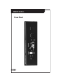
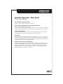
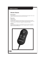
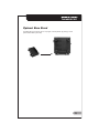
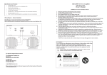
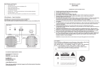
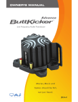
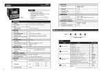
IMPORTANT SAFETY INSTRUCTIONS READ BEFORE OPERATING EQUIPMENT 1. Read these instructions and keep them for future reference. 2. Carefully follow instructions and take heed to all warnings. 3. Do not use this apparatus near water. 4. Clean amplifier housing only with a slightly damp cloth. 5. Do not block any of the ventilation openings. Install in accordance with the manufacturers instructions. 6. Do not install near any heat source such as radiators, heat registers, stoves, or other electrical devices (including amplifiers) that produce heat. 7. Do not defeat the safety purpose of the grounding type plug. A grounding type plug has two blades and a third prong. The third prong is provided for your safety. If the provided plug does not fit easily into your outlet, consult an electrician for replacement of the obsolete outlet before attempting to power up the amplifier. 8. Prevent the power cord from being walked on or pinched, particularly at the plug or at the point where it exits from the amplifier. 9. Use only attachments and accessories specified by the manufacturer. When uncertain about specifications, please first consult the manufacturers website and see the FAQs; if still uncertain please call the phone numbers listed in this manual for tech support. 10. When this apparatus is placed on a cart, stand or table, make sure that it is sufficiently stable and can accommodate the weight of this unit. When placed on a cart with wheels, use extra caution so that it does not tip over when the cart is moving. 11. Unplug this unit during lightning storms or when it is unused for an extended period of time. This device may be plugged into a surge protector or power strip, but should NOT be plugged into a UPS (uninterruptible power supply). 12. DO NOT LEAVE THIS AMPLIFIER IN STAND BY MODE WHEN NO ONE IS IN ATTENDANCE. For safety and to ensure long life, turn the amplifier power switch to the OFF position when unit is not being used. 13. Refer all servicing to qualified service personnel. Servicing is required when the apparatus has been damaged in any way. This would include damage to the power supply cord or plug, whenever liquid has been spilled or objects have fallen into the apparatus, when the apparatus has been exposed to rain or moisture, when it does not operate normally, or whenever it has been dropped. 14. Where the MAINS plug or an appliance coupler is used as the disconnect device, the disconnect device shall remain readily operable. CAUTION RISK OF ELECTRIC SHOCK DO NOT OPEN CAUTION: TO REDUCE THE RISK OF ELECTRIC SHOCK, DO NOT REMOVE COVER (OR BACK) NO USER-SERVICEABLE PARTS INSIDE REFER SERVICING TO QUALIFIED SERVICE PERSONNEL The lightning flash with arrowhead symbol within an equilateral triangle, is intended to alert the user to the presence of uninsulated "dangerous voltage " within the product's enclosure that may be of sufficient magnitude to constitute a risk of electric shock to persons. The exclamation point within an equilateral triangle is intended to alert the user to the presence of important operating and maintenance (servicing) instructions in the literature accompanying the product. Earth symbol. The apparatus shall be connected to a mains socket outlet with a protective earthing connection. Contents......................................................Page Number Important Safety Instructions.............................................02 Amplifier Warnings / Cautions..............................................03 Amplifier Usage Guidelines..........................................05 Amplifier Specifications......................................................05 Included Accessories............................................................05 Amplifier Operation - Front Panel...................................06 - 07 Amplifier Operation - Rear Panel..................................08 - 09 Remote Control...........................................................10 Optional Base Stand.................................................11 Contact Information.......................................Back Cover Warranty......................................................Back Cover Amplifier Usage Guidelines This amplifier is designed for use with the following ButtKicker® transducer models only: BK-GR...................(quantity 1 max) BK-mini-LFE............(quantity 2 max) BK-mini-CT..............(quantity 1 max) BK4-4....................(quantity 2 max) BK4-2...................(quantity 1 max) Amplifier Specifications Dimensions: 9.5 L x 7.5 W x 2.76 H Weight: 5.6 lbs./2.5 kgs. Power Output: 90 watts rms @ 2 ohms 120v Only (also available in 240v) Frequency Response: 10 - 300Hz Input Sensitivity: 80 mVolt Included Accessories: Wired Remote Control Base Stand AC Power Cord Front Panel Amplifier Operation - Front Panel (From Left to Right) POWER BUTTON The Power Button engages and disengages amplifier circuits. Check all amplifier connections and verify the AC line power source before engaging the Power Button. If in Standby mode, the amplifier will be brought into full On mode automatically when an input signal is reapplied, or manually by pressing the Power Button twice to turn the amplifier off, and then back on. POWER STATUS INDICATOR (Orange/Green LED) Orange indicates two possible modes. (1) the amplifier is in Off mode, or (2) the amplifier was on, but reverted to Standby mode after 20 minutes of not receiving input signal. If the amplifier is in Standby mode (Orange), and an input signal is reapplied, the amplifier circuits will automatically energize and the indicator light will turn green. Green indicates that all amplifier circuits are energized and ready to function. After 20 minutes of no input signal, the amplifier will revert back to the low power Standby mode. LOW FILTER CUTOFF PUSH SWITCH Pushing this switch to the in position engages the filter circuit which reduces all frequencies below 25Hz (-3dB) at a rolloff rate of 12dB per octave. HIGH CUTOFF FREQUENCY CONTROL Effective only when the High Cutoff Switch is pushed in. This determines the frequency above which frequencies are rolled off. HIGH CUTOFF FILTER PUSH SWITCH Engages the circuit (including the High Cutoff Frequency Control to its left) that rolls off the higher frequencies (rolloff rate of 12dB per octave). CLIP INDICATOR LIGHT (Red LED) Illuminates when maximum output is approached. SIGNAL INDICATOR LIGHT (Green LED) Illuminates when a signal passes through the circuits to the amplifiers output terminal. VOLUME (-) (+) Short push to step transducer intensity down or up respectively. Hold for multiple steps up and down. NOTE: This feature is labeled Intensity on the Remote Control. REMOTE CONTROL Connect the wired remote here. Please note connectors correct side up. Rear Panel Amplifier Operation - Rear Panel (From Left to Right) IEC TYPE POWER CORD RECEPTICAL Attach one end of power cord here for operation. FUSE HOLDER (INTEGRATED INTO THE POWER RECEPTICAL) Fuse for 120v operation:T4AL 250VAC. A spare fuse is also contained in the fuse holder for your convenience. Pull straight out after removing power cord. Both the active fuse and the spare fuse are removed. HARD POWER SWITCH Removes all AC power from all internal circuits of the amplifier. Set this switch to the OFF position to consume no power over a long period of time. LINE IN/OUT RCA/phono jacks. The Output connector is a wired duplicate of the In connector and is used as an output to daisy chain multiple amplifiers. The number of units daisy chained should be limited to 4. If more are used, an audio distribution amplifier should be used to increase the total possible amplifiers. SPEAKER LEVEL OUTPUT BINDING POSTS Used for attaching speaker wire to the ButtKicker® Unit(s). NOTE: Please see the Amplifier Usage Guidelines on page 5 for a list of ButtKicker® models that can be used with this amplifier. Turn the amplifier off before connecting to the Speaker Output. Wire sizes of 14 gauge and larger are recommended. Binding posts will accept banana type connectors or bare wire. Remote Control Connection Plug the Remote Control into the front of the BKA-130-C Power Amplifier where it says Remote. Please note the correct side up on the connector. Operation POWER BUTTON The Power Button duplicates the Power Button on the front panel of the amplifier. Please refer to the POWER BUTTON and POWER STATUS INDICATOR sections under Amplifier Operation - Front Panel on page 07 for operation information INTENSITY The Intensity Buttons duplicate the Volume Buttons on the front panel of the amplifier. Please refer to the VOLUME (-) (+) section under Amplifier Operation - Front Panel on page 07 for operation instructions. Optional Base Stand The BKA-130-C can also be set in an upright, vertical position by placing it in the optional Base Stand (included).