1
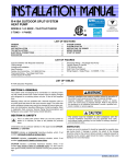
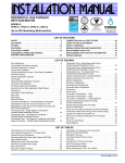
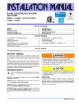
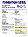
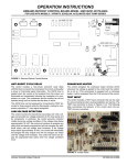
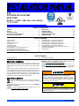
INSTALLATION MANUAL
R-22
OUTDOOR SPLIT-SYSTEM
HEAT PUMP
ISO 9001
Certified Quality
Management System
MODELS: 13 SEER - YMB / HC3A / HL3A SERIES
1.5 TO 5 TONS
LISTED
TABLE OF CONTENTS
GENERAL . . . . . . . . . . . . . . . . . . . . . . . . . . . . . . . . . . . . . . . . . . . . . . 1
SAFETY . . . . . . . . . . . . . . . . . . . . . . . . . . . . . . . . . . . . . . . . . . . . . . . . 1
UNIT INSTALLATION . . . . . . . . . . . . . . . . . . . . . . . . . . . . . . . . . . . . . 2
INSTALLATIONS REQUIRING TXV . . . . . . . . . . . . . . . . . . . . . . . . . . 5
ELECTRICAL CONNECTIONS . . . . . . . . . . . . . . . . . . . . . . . . . . . . . . 5
EVACUATION . . . . . . . . . . . . . . . . . . . . . . . . . . . . . . . . . . . . . . . . . .12
SYSTEM CHARGE . . . . . . . . . . . . . . . . . . . . . . . . . . . . . . . . . . . . . .12
SYSTEM OPERATION . . . . . . . . . . . . . . . . . . . . . . . . . . . . . . . . . . . .13
INSTRUCTING THE OWNER . . . . . . . . . . . . . . . . . . . . . . . . . . . . . .13
WIRING DIAGRAM . . . . . . . . . . . . . . . . . . . . . . . . . . . . . . . . . . . . . .14
LIST OF FIGURES
Typical Installation . . . . . . . . . . . . . . . . . . . . . . . . . . . . . . . . . . . . . . . . 2
Tubing Hanger . . . . . . . . . . . . . . . . . . . . . . . . . . . . . . . . . . . . . . . . . . . 3
Underground Installation . . . . . . . . . . . . . . . . . . . . . . . . . . . . . . . . . . . 3
Heat Protection . . . . . . . . . . . . . . . . . . . . . . . . . . . . . . . . . . . . . . . . . . 4
Typical Field Wiring . . . . . . . . . . . . . . . . . . . . . . . . . . . . . . . . . . . . . . . 6
CFM Selection Board . . . . . . . . . . . . . . . . . . . . . . . . . . . . . . . . . . . . . . 6
Thermostat Wiring – Single Stage Heat Pump PSC Air Handler (with Hot Heat Pump) . . . . . . . . . . . . . . . . . . . . . . . . 7
Thermostat Wiring – Single Stage Heat Pump Single Stage PSC Furnace (with Hot Heat Pump) . . . . . . . . . . . . . . . . 8
Thermostat Wiring – Single Stage Heat Pump PSC Modulating Furnace (with Hot Heat Pump) . . . . . . . . . . . . . . . . .9
Thermostat Wiring – Single Stage Heat Pump Variable Speed Air Handler (with Hot Heat Pump) . . . . . . . . . . . . . . .10
Thermostat Wiring – Single Stage Heat Pump Variable Speed Modulating Furnace (with Hot Heat Pump) . . . . . . . .11
Heat Pump Flow Diagram . . . . . . . . . . . . . . . . . . . . . . . . . . . . . . . . . .12
Wiring Diagram . . . . . . . . . . . . . . . . . . . . . . . . . . . . . . . . . . . . . . . . . .14
LIST OF TABLES
Defrost Initiate Curves . . . . . . . . . . . . . . . . . . . . . . . . . . . . . . . . . . . . 13
SECTION I: GENERAL
The outdoor units are designed to be connected to a matching indoor
coil with sweat connect lines. Sweat connect units are factory charged
with refrigerant for a matching indoor coil plus 15 feet of field supplied
lines.
Matching indoor coils are available with a thermal expansion valve or
an orifice liquid feed sized for the most common usage. The orifice size
and/or refrigerant charge may need to be changed for some indoor-outdoor unit combinations, elevation differences, or total line lengths. Refer
to Application Data covering “General Piping Recommendations and
Refrigerant Line Length” (Part Number 036-61920-001).
SECTION II: SAFETY
This is a safety alert symbol. When you see this symbol on
labels or in manuals, be alert to the potential for personal
injury.
R-22 Saturated Properties . . . . . . . . . . . . . . . . . . . . . . . . . . . . . . . . 13
WARNING indicates a potentially hazardous situation, which, if not
avoided, could result in death or serious injury.
CAUTION indicates a potentially hazardous situation, which, if not
avoided may result in minor or moderate injury. It is also used to
alert against unsafe practices and hazards involving only property damage
Improper installation may create a condition where the operation of
the product could cause personal injury or property damage.
Improper installation, adjustment, alteration, service, or maintenance can cause injury or property damage. Refer to this manual
for assistance or for additional information, consult a qualified contractor, installer, or service agency.
Understand and pay particular attention to the signal words DANGER,
WARNING, or CAUTION.
DANGER indicates an imminently hazardous situation, which, if not
avoided, will result in death or serious injury.
This product must be installed in strict compliance with the
enclosed installation instructions and any applicable local, state,
and national codes including, but not limited to building, electrical,
and mechanical codes.
361813-UIM-A-0208
361813-UIM-A-0208
INSPECTION
SECTION III: UNIT INSTALLATION
As soon as a unit is received, it should be inspected for possible damage during transit. If damage is evident, the extent of the damage
should be noted on the carrier’s delivery receipt. A separate request for
inspection by the carrier’s agent should be made in writing. See Local
Distributor for more information.
LOCATION
Before starting the installation, select and check the suitability of the
location for both the indoor and outdoor unit. Observe all limitations and
clearance requirements.
The outdoor unit must have sufficient clearance for air entrance to the
condenser coil, for air discharge, and for service access. See Figure 1.
LIMITATIONS
The unit should be installed in accordance with all National, State, and
Local Safety Codes and the limitations listed below:
1.
Limitations for the indoor unit, coil, and appropriate accessories
must also be observed.
2.
The outdoor unit must not be installed with any duct work in the air
stream. The outdoor fan is the propeller type and is not designed
to operate against any additional external static pressure.
3.
The maximum and minimum conditions for operation must be
observed to assure a system that will give maximum performance
with minimum service.
AIR TEMPERATURE AT
OUTDOOR COIL, °F
Min.
AIR TEMPERATURE AT
INDOOR COIL, °F
Max.
Min.
Max.
DB
Cool
DB
Heat
DB
Cool
DB
Heat
WB
Cool
DB
Heat
WB
Cool
DB
Heat
50
-10
115
75
57
501
72
80
NOTE: For multiple unit installations, units must be spaced a minimum
of 18 inches apart. (Coil face to coil face.)
If the unit is to be installed on a hot sun exposed roof or a black-topped
ground area, the unit should be raised sufficiently above the roof or
ground to avoid taking the accumulated layer of hot air into the outdoor
unit.
Provide an adequate structural support.
ADD-ON REPLACEMENT/RETROFIT
The following steps should be performed in order to insure proper system operation and performance.
1.
Change-out of the indoor coil to an approved R-22 coil/ condensing unit combination with the appropriate metering device.
2.
If the outdoor unit is being replaced due to a compressor burnout,
then installation of a 100% activated alumina suction-line filter
drier is required, in addition to the factory installed liquid-line drier.
Operate the system for 10 hours. Monitor the suction drier pressure drop. If the pressure drop exceeds 3 psig, replace both the
suction-line and liquid-line driers. After a total of 10 hours run time
where the suction-line pressure drop has not exceeded 3 psig,
replace the liquid line drier, and remove the suction-line drier.
Never leave a suction-line drier in the system longer than 50 hours
of run time.
1. Operation below this temperature is permissible for a short period of
time, during morning warm-up.
4.
The maximum allowable line length for this product is 75 feet.
THERMOSTAT
NEC CLASS 1
WIRING
TO INDOOR
BLOWER
NEC CLASS 2
WIRING
WEATHERPROOF
DISCONNECT SWITCH
48” OVERHEAD
CLEARANCE
TO COIL
SEAL OPENINGS WITH
PERMAGUM OR EQUIVALENT
24” SERVICE
ACCESS
CLEARANCE
18” FRONT
& SIDES
NOTE: ALL OUTDOOR WIRING MUST BE WEATHERPROOF
FIGURE 1: Typical Installation
2
Unitary Products Group
361813-UIM-A-0208
GROUND INSTALLATION
PIPING CONNECTIONS
The unit may be installed at ground level on a solid base that will not
shift or settle, causing strain on the refrigerant lines and possible leaks.
Maintain the clearances shown in Figure 1 and install the unit in a level
position.
The outdoor unit must be connected to the indoor coil using field supplied refrigerant grade copper tubing that is internally clean and dry.
Units should be installed only with the tubing sizes for approved system
combinations as specified in Tabular Data Sheet. The charge given is
applicable for total tubing lengths up to 15 feet. See Application Data
Part Number 036-61920-001 for installing tubing of longer lengths and
elevation differences.
Normal operating sound levels may be objectionable if the unit is placed
directly under windows of certain rooms (bedrooms, study, etc.).
Condensate will drain from beneath the coil of the outdoor unit during
the defrost cycle. Normally this condensate may be allowed to drain
directly on the ground.
The outdoor unit should not be installed in an area where mud or
ice could cause personal injury. Remember that condensate will
drip from the unit coil during heat and defrost cycles and that this
condensate will freeze when the temperature of the outdoor air is
below 32°F.
Elevate the unit sufficiently to prevent any blockage of the air entrances
by snow in areas where there will be snow accumulation. Check the
local weather bureau for the expected snow accumulation in your area.
Isolate the unit from rain gutters to avoid any possible wash out of the
foundation.
ROOF INSTALLATION
When installing units on a roof, the structure must be capable of supporting the total weight of the unit, including a pad, lintels, rails, etc.,
which should be used to minimize the transmission of sound or vibration into the conditioned space.
UNIT PLACEMENT
1.
NOTE: Using a larger than specified line size could result in oil return
problems. Using too small a line will result in loss of capacity and other
problems caused by insufficient refrigerant flow. Slope horizontal vapor
lines at least 1" every 20 feet toward the outdoor unit to facilitate proper
oil return.
PRECAUTIONS DURING LINE INSTALLATION
1.
Install the lines with as few bends as possible. Care must be taken
not to damage the couplings or kink the tubing. Use clean hard
drawn copper tubing where no appreciable amount of bending
around obstruction is necessary. If soft copper must be used, care
must be taken to avoid sharp bends which may cause a restriction.
2.
The lines should be installed so that they will not obstruct service
access to the coil, air handling system, or filter.
3.
Care must also be taken to isolate the refrigerant lines to minimize
noise transmission from the equipment to the structure.
4.
The vapor line must be insulated with a minimum of 1/2" foam rubber insulation (Armaflex or equivalent). Liquid lines that will be
exposed to direct sunlight and/or high temperatures must also be
insulated.
Tape and suspend the refrigerant lines as shown. DO NOT allow tube
metal-to-metal contact. See Figure 3.
5.
Use PVC piping as a conduit for all underground installations as
shown in Figure 4. Buried lines should be kept as short as possible
to minimize the build up of liquid refrigerant in the vapor line during
long periods of shutdown
6.
Pack fiberglass insulation and a sealing material such as permagum around refrigerant lines where they penetrate a wall to reduce
vibration and to retain some flexibility.
7.
See Form 690.01-AD1V for additional piping information.
Provide a base in the pre-determined location.
2.
Remove the shipping carton and inspect for possible damage.
3.
Compressor tie-down bolts should remain tightened.
4.
Position the unit on the base provided.
NOTE: Heat pumps will defrost periodically resulting in water drainage.
The unit should not be located where water drainage may freeze and
create a hazardous condition - such as sidewalks and steps.
Sheet Metal Hanger
LIQUID LINE FILTER-DRIER
Liquid
Line
The heat pumps have a solid core bi-flow filter/drier located on the liquid
line.
Incorrect
NOTE: Replacements for the liquid line drier must be exactly the same
as marked on the original factory drier. See Source 1 for O.E.M.
replacement driers.
Tape
Correct
Insulated Vapor Line
Failure to do so or using a substitute drier or a granular type may
result in damage to the equipment.
FIGURE 2: Tubing Hanger
TO INDOOR COIL
Apply with Models
Filter-Drier
Source 1 Part No.
YMB / HC3A / HL3A
026 - 25512 - 000
All Sizes
LIQUID LINE
PVC
TO OUTDOOR UNIT
INSULATED
CAP
VAPOR LINE
CONDUIT
FIGURE 3: Underground Installation
Unitary Products Group
3
361813-UIM-A-0208
PRECAUTIONS DURING BRAZING OF LINES
All outdoor unit and evaporator coil connections are copper-to-copper
and should be brazed with a phosphorous-copper alloy material such
as Silfos-5 or equivalent. DO NOT use soft solder. The outdoor units
have reusable service valves on both the liquid and vapor connections.
The total system refrigerant charge is retained within the outdoor unit
during shipping and installation. The reusable service valves are provided to evacuate and charge per this instruction.
Serious service problems can be avoided by taking adequate precautions to assure an internally clean and dry system.
Dry nitrogen should always be supplied through the tubing while it
is being brazed, because the temperature is high enough to cause
oxidation of the copper unless an inert atmosphere is provided. The
flow of dry nitrogen should continue until the joint has cooled.
Always use a pressure regulator and safety valve to insure that only
low pressure dry nitrogen is introduced into the tubing. Only a small
flow is necessary to displace air and prevent oxidation.
FIGURE 4: Heat Protection
PRECAUTIONS DURING BRAZING SERVICE VALVE
Precautions should be taken to prevent heat damage to service valve
by wrapping a wet rag around it as shown in Figure 5. Also, protect all
painted surfaces, insulation, and plastic base during brazing. After brazing cool joint with wet rag.
The evaporator is pressurized.
4.
Braze the liquid line to the evaporator liquid connection. Nitrogen
should be flowing through the evaporator coil.
5.
This is not a backseating valve. The service access port has a
valve core. Opening or closing valve does not close service access
port.
If the valve stem is backed out past the chamfered retaining wall,
the O-ring can be damaged causing leakage or system pressure
could force the valve stem out of the valve body possibly causing
personal injury.
Slide the grommet away from the vapor connection at the indoor
coil. Braze the vapor line to the evaporator vapor connection. After
the connection has cooled, slide the grommet back into original
position. Refer to the Tabular Data Sheet for proper vapor line sizing.
6.
Valve can be opened by removing the plunger cap and fully inserting a
hex wrench into the stem and backing out counter-clockwise until valve
stem just touches the chamfered retaining wall.
Protect the vapor valve with a wet rag and braze the vapor line
connection to the outdoor unit. The nitrogen flow should be exiting
the system from the vapor service port connection. After this connection has cooled, remove the nitrogen source from the liquid fitting service port.
7.
Replace the Schrader core in the liquid and vapor valves.
8.
Go to “SECTION IV” for TXV installation.
Connect the refrigerant lines using the following procedure:
9.
Leak test all refrigerant piping connections including the service
port flare caps to be sure they are leak tight. DO NOT OVERTIGHTEN (between 40 and 60 inch - lbs. maximum).
1.
Remove the cap and Schrader core from both the liquid and vapor
service valve service ports at the outdoor unit. Connect low pressure nitrogen to the liquid line service port.
2.
Braze the liquid line to the liquid valve at the outdoor unit. Be sure
to wrap the valve body with a wet rag. Allow the nitrogen to continue flowing. Refer to the Tabular Data Sheet for proper liquid line
sizing.
3.
4
Carefully remove the rubber plugs from the evaporator liquid and
vapor connections at the indoor coil.
10. Evacuate the vapor line, evaporator, and the liquid line to 500
microns or less.
NOTE: Line set and indoor coil can be pressurized to 250 psig with dry
nitrogen and leak tested with a bubble type leak detector. Then release
the nitrogen charge.
NOTE: Do not use the system refrigerant in the outdoor unit to purge or
leak test.
11. Replace cap on service ports. Do not remove the flare caps from
the service ports except when necessary for servicing the system.
Unitary Products Group
361813-UIM-A-0208
Do not connect manifold gauges unless trouble is suspected.
Approximately 3/4 ounce of refrigerant will be lost each time a standard manifold gauge is connected.
12. Release the refrigerant charge into the system. Open both the liquid and vapor valves by removing the plunger cap and with an
allen wrench back out counter-clockwise until valve stem just
touches the chamfered retaining wall. See Page 4 "PRECAUTIONS DURING BRAZING SERVICE VALVE".
13. Replace plunger cap finger tight, then tighten an additional 1/12
turn (1/2 hex flat). Cap must be replaced to prevent leaks.
Dry nitrogen should always be supplied through the tubing while it
is being brazed, because the temperature is high enough to cause
oxidation of the copper unless an inert atmosphere is provided. The
flow of dry nitrogen should continue until the joint has cooled.
Always use a pressure regulator and safety valve to insure that only
low pressure dry nitrogen is introduced into the tubing. Only a small
flow is necessary to displace air and prevent oxidation.
All connections to be brazed are copper-to-copper and should be
brazed with a phosphorous-copper alloy material such as Silfos-5 or
equivalent. DO NOT use soft solder.
Install the TXV bulb to the vapor line near the equalizer line, using the
two bulb clamps furnished with the TXV assembly. Ensure the bulb is
making maximum contact. Refer to TXV installation instruction for view
of bulb location.
Never attempt to repair any brazed connections while the system is
under pressure. Personal injury could result.
See "System Charge” section for checking and recording system
charge.
SECTION IV: INSTALLATIONS REQUIRING
TXV
For installations requiring a TXV, the following are the basic steps for
installation. For detailed instructions, refer to the Installation Instructions
accompanying the TXV kit.
In all cases, mount the TXV bulb after vapor line is brazed and has
had sufficient time to cool.
a.
Bulb should be installed on a horizontal run of the vapor line if
possible. On lines under 7/8" OD the bulb may be installed on
top of the line. With 7/8" OD and over, the bulb should be
installed at the position of about 2 or 10 o'clock.
b.
If bulb installation is made on a vertical run, the bulb should
be located at least 16 inches from any bend, and on the tubing sides opposite the plane of the bend. The bulb should be
positioned with the bulb tail at the top, so that the bulb acts as
a reservoir.
c.
Bulb should be insulated using thermal insulation provided to
protect it from the effect of the surrounding ambient temperature.
Install TXV kit as follows:
1.
First, relieve the holding charge by depressing the Schrader valve
located in the end of the liquid line.
2.
After holding charge is completely discharged, loosen and remove
the liquid line fitting from the orifice distributor assembly. Note that
the fitting has right hand threads.
3.
Remove the orifice from the distributor body using a small diameter wire or paper clip. Orifice is not used when the TXV assembly
is installed.
4.
After orifice is removed, install the thermal expansion valve to the
orifice distributor assembly with supplied fittings. Hand tighten and
turn an additional 1/8 turn to seal. Do not overtighten fittings.
5.
Reinstall the liquid line to the top of the thermal expansion valve.
Hand modify the liquid line to align with casing opening.
6.
Install the TXV equalizer line into the vapor line as follows:
7.
a.
Select a location on the vapor line for insertion of the equalizer line which will not interfere with TXV bulb placement.
b.
Use an awl to punch through the suction tube and insert the
awl to a depth to achieve a 1/8” diameter hole.
Install TXV equalizer line in 1/8” hole previously made in vapor
line. Equalizer line should not be bottomed out in vapor line. Insert
equalizer line at least 1/4” in the vapor line. Braze equalizer line
making sure that tube opening is not brazed closed.
Unitary Products Group
SECTION V: ELECTRICAL CONNECTIONS
GENERAL INFORMATION & GROUNDING
Check the electrical supply to be sure that it meets the values specified
on the unit nameplate and wiring label.
Power wiring, control (low voltage) wiring, disconnect switches, and
over current protection must be supplied by the installer. Wire size
should be sized per NEC requirements.
All field wiring must USE COPPER CONDUCTORS ONLY and
be in accordance with Local, National Fire, Safety & Electrical
Codes. This unit must be grounded with a separate ground
wire in accordance with the above codes.
The complete connection diagram and schematic wiring label is located
on the inside surface of the unit service access panel and in Figure 18
of this instruction.
5
361813-UIM-A-0208
FIELD CONNECTIONS POWER WIRING
DEHUMIDIFICATION CONTROL
1.
Install the proper size weatherproof disconnect switch outdoors
and within sight of the unit.
2.
Remove the screws at the bottom of the corner cover. Slide corner
cover down and remove from unit. See Figure 6.
A dehumidification control accessory 2HU06700124 may be used with
variable speed air handlers or furnaces in high humidity areas. This
control works with the variable speed indoor unit to provide cooling at a
reduced air flow, lowering evaporator temperature and increasing latent
capacity. The humidistat in this control opens the humidistat contacts on
humidity rise. To install, refer to Figures 7-11 in this manual and also
refer to the installation manual packed with the control accessory
2HU06700124.
3.
Run power wiring from the disconnect switch to the unit.
4.
Remove the service access panel to gain access to the unit wiring.
Route wires from disconnect through power wiring opening provided and into the unit control box as shown in Figure 6.
5.
Install the proper size time-delay fuses or circuit breaker, and
make the power supply connections.
6.
Energize the crankcase heater if equipped to save time by preheating the compressor oil while the remaining installation is completed.
Prior to the installation of the dehumidification control, the jumper
across the HUMIDISTAT terminals on the indoor variable speed air handler or furnace CFM selection board must be removed.
During cooling, if the relative humidity in the space is higher than the
desired set point of the dehumidification control, the variable speed
blower motor will operate at lower speed until the dehumidification control is satisfied. A 40-60% relative humidity level is recommended to
achieve optimum comfort.
If a dehumidification control is installed, it is recommended that a minimum air flow of 325 cfm/ton be supplied at all times.
SERVICE
ACCESS
PANEL
For additional connection diagrams for all UPG equipment refer to “Low
Voltage System Wiring” document available online at www.upgnet.com
in the Product Catalog Section.
CFM SELECTION BOARD SETTINGS
CFM SELECTION BOARD
TAP SELECTION
CONTROL
WIRING
CORNER
COVER
POWER
WIRING
D
C
B
A
D
C
B
A
COOL
HEAT
ADJ
DELAY
REMOVE FOR
HEAT PUMP
HUMIDISTAT
FIGURE 5: Typical Field Wiring
FIELD CONNECTIONS CONTROL WIRING
1.
Route low voltage wiring into bottom of control box as shown in
Figure 6. Make low voltage wiring connection inside jumper box
per Figures 7-11.
2.
Replace the corner cover and service access panel that were
removed in Steps 2 and 4 of the “Field Connections Power Wiring”
section.
3.
All field wiring to be in accordance with national electrical codes
(NEC) and/or local-city codes.
NOTE: A Start Assist Kit is available and recommended for long line set
applications or in areas of known low voltage problems.
4. Mount the thermostat about 5 ft. above the floor, where it will be
exposed to normal room air circulation. Do not place it on an outside wall or where it is exposed to the radiant effect from exposed
glass or appliances, drafts from outside doors or supply air grilles.
5.
FIGURE 6: CFM Selection Board
For proper system operation the CFM Selection Board jumpers must be
set properly.
Refer to the Tabular Data Sheet for the recommended air flow settings
for each size condensing unit.
Set the cooling speed per the instructions for the air handler or furnace
by selecting the correct COOL and ADJ taps. Verify the airflow using
the LED display on the CFM selection board.
The HEAT PUMP jumper MUST be removed for proper system operation.
The HUMIDISTAT jumper must also be removed if a dehumidistat is
installed.
Route the 24-volt control wiring (NEC Class 2) from the outdoor
unit to the indoor unit and thermostat.
NOTE: To eliminate erratic operation, seal the hole in the wall at the
thermostat with permagum or equivalent to prevent air drafts affecting
the operation of in the thermostat.
6
Unitary Products Group
361813-UIM-A-0208
For additional connection diagrams for all UPG equipment refer to “Low Voltage System Wiring” document available online at www.upgnet.com in the
Product Catalog Section.
HP 9A
Single Stage Heat Pump – PSC Air Handler (With Hot Heat Pump Operation)
ID MODELS
THERMOSTAT
THERMOSTAT
THERMOSTAT
*DN22U00124
*BP21H50124
*BN21H00124
*DP21H40124
*DN21H00124
*DP32H70124
OD MODELS
AHP
SHP
MA
YZB
YMB
H*3
PSC
AIR HANDLER
PSC
AIR HANDLER
SINGLE STAGE
HEAT PUMP
2
YORKGUARD VI
CONTROL
C
24 – Volt Common
C
24 – Volt Common
C
24 – Volt Common
C
24 – Volt Common
C
24 – Volt Common
Y1
First Stage Compressor
Y1
First Stage Compressor
Y1
First Stage Compressor
Y1
Single Stage Compressor
Y1
Single Stage Compressor
R
24 – Volt Hot
(Heat XFMR)
R
24 – Volt Hot
R
24 – Volt Hot
R
24 – Volt Hot
R
24 – Volt Hot
G
Fan
G
Fan
G
Fan
G
Fan
E
Emergency Heat
E
Emergency Heat
E
Emergency Heat
W1
First Stage Aux. Heat
W1 OUT
First Stage Heat
W2
Third Stage Heat
W2
Second Stage Aux. Heat
W2 OUT
Second Stage Heat
R
24 – Volt Hot
(Cool XFMR)
O/B
Reversing Valve
O
Reversing Valve
Energized in Cool
O
Reversing Valve
Energized in Cool
Y/Y2
Second or Full
Stage Compressor
O
Reversing Valve
Energized in Cool
L
Malfunction Light
L
Malfunction Light
L
Malfunction Light
X/L
Malfunction Light
Y2 OUT
Second Stage Compressor
O
Reversing Valve
Energized in Cool
X/L
Malfunction Light
Y2
Y2
Y2
Second Stage Compressor Second Stage CompressorSecond Stage Compressor
AUX
Auxiliary Heat
W2
Second Stage Heat
Y2
Second Stage Compressor
W1
Second Stage Aux. Heat
W
Auxiliary Heat
3
Step 1 of Thermostat
Thermostat Installer Setup
B/O Switch on Thermostat Installer / Configuration
1-System Type-must be set
must be in the O position
Menu must be set to
to 5 – 2 Heat/1 Heat Pump
Heat Pump 1
Thermostat Installer Setup
Second stage auxiliary
2-Changeover Valve-must
heat will be controlled by
be set to 0 – O/B terminal
the thermostat, not the
Energized in Cooling
heat pump control when
wired as shown.
3
Part Number:
S1-2HU16700124
1
External Humidistat
(Optional)
Open on Humidity Rise
HUM
Humidity Switch
Open on Humidity Rise
24VAC Humidifier
(Optional)
HUM OUT
(24VAC out)
24VAC
Electronic Air Cleaner
(Optional)
EAC (24VAC out)
Electronic Air Cleaner
BSG
Bonnet Sensor
BS
Bonnet Sensor
Change Hot Heat Pump
jumper on the heat pump
control to “ON”
Move the MODE
jumper to “HP”
Move HUM STAT
jumper to “YES”
if humidistat is to be used.
Refer to AH documentation
for W1 and W2 electric
heat staging options.
Part Numbers:
SAP = Legacy
159480 = 031-09156
2
Part Numbers:
SAP = Legacy
126768 = 031-09137
18395 = 031-01996
340512 = 031-09178
1
FIGURE 7: Thermostat Wiring – Single Stage Heat Pump - PSC Air Handler (with Hot Heat Pump)
Unitary Products Group
7
361813-UIM-A-0208
HP 12A
Single Stage Heat Pump – Single Stage PSC Furnace (With Hot Heat Pump Operation)
ID MODELS
PS(8/9)
THERMOSTAT
THERMOSTAT
THERMOSTAT
*DN22U00124
*BP21H50124
*BN21H00124
*DP21H40124
*DN21H00124
*DP32H70124
OD MODELS
L*8S
YZB
F*(8/9)S
G8C
YMB
G*(8/9)S
GF(8/9)
H*3
G*9F
SINGLE
STAGE PSC
FURNACE
SINGLE STAGE
HEAT PUMP
SINGLE STAGE PSC
FURNACE
2
YORKGUARD VI
CONTROL
C
24 – Volt Common
C
24 – Volt Common
C
24 – Volt Common
C
24 – Volt Common
C
24 – Volt Common
Y1
First Stage Compressor
Y1
First Stage Compressor
Y1
First Stage Compressor
Y1
Single Stage Compressor
Y1
Single Stage Compressor
R
24 – Volt Hot
(Heat XFMR)
R
24 – Volt Hot
R
24 – Volt Hot
R
24 – Volt Hot
R
24 – Volt Hot
G
Fan
G
Fan
G
Fan
G
Fan
E
Emergency Heat
E
Emergency Heat
E
Emergency Heat
W
First Stage Heat
W1 OUT
First Stage Heat
W2
Third Stage Heat
R
24 – Volt Hot
(Cool XFMR)
W2 OUT
Second Stage Heat
Y / Y2
Second or Full
Stage Compressor
Y2 OUT
Second Stage Compressor
O/B
Reversing Valve
O
Reversing Valve
Energized in Cool
O
Reversing Valve
Energized in Cool
O
Reversing Valve
Energized in Cool
L
Malfunction Light
L
Malfunction Light
L
Malfunction Light
X/L
Malfunction Light
Y2
Y2
Y2
Second Stage CompressorSecond Stage CompressorSecond Stage Compressor
AUX
Auxiliary Heat
W2
Second Stage Heat
Y2
Second Stage Compressor
W1
Second Stage Aux. Heat
3
External Humidistat
(Optional)
Open on Humidity Rise
W
Auxiliary Heat
Bonnet Sensor
(Optional)
24VAC Humidifier
(Optional)
Step 1 of Thermostat
Thermostat Installer Setup
B/O Switch on Thermostat Installer / Configuration
1-System Type-must be set
must be in the O position
Menu must be set to
to 5 – 2 Heat/1 Heat Pump
Heat Pump 1
Thermostat Installer Setup
Part Number:
S1-2HU16700124
BSG
Bonnet Sensor
BS
Bonnet Sensor
Change FFuel jumper
on the heat pump control
to “ON”
Change Hot Heat Pump
jumper on the heat pump
control to “ON”
2-Changeover Valve-must
be set to 0 – O/B terminal
Energized in Cooling
3
1
Part Numbers:
SAP = Legacy
265902 = 031-09167
2
Part Numbers:
SAP = Legacy
126768 = 031-09137
18395 = 031-01996
340512 = 031-09178
1
FIGURE 8: Thermostat Wiring – Single Stage Heat Pump - Single Stage PSC Furnace (with Hot Heat Pump)
8
Unitary Products Group
361813-UIM-A-0208
HP 17A
Single Stage Heat Pump – PSC Modulating Furnace (With Hot Heat Pump Operation)
OD MODELS
ID MODELS
THERMOSTAT
THERMOSTAT
THERMOSTAT
*DN22U00124
*BP21H50124
*BN21H00124
*DP21H40124
*DN21H00124
*DP32H70124
PM9
YZB
FC9M
FL9M
YMB
H*3
PSC
MODULATING
FURNACE
SINGLE STAGE
HEAT PUMP
PSC
2
MODULATING FURNACE
YORKGUARD VI
CONTROL
C
24 – Volt Common
C
24 – Volt Common
C
24 – Volt Common
C
24 – Volt Common
C
24 – Volt Common
Y1
First Stage Compressor
Y1
First Stage Compressor
Y1
First Stage Compressor
Y1
Single Stage Compressor
Y1
Single Stage Compressor
R
24 – Volt Hot
(Heat XFMR)
R
24 – Volt Hot
R
24 – Volt Hot
R
24 – Volt Hot
R
24 – Volt Hot
G
Fan
G
Fan
G
Fan
G
Fan
E
Emergency Heat
E
Emergency Heat
E
Emergency Heat
W
Modulating Heat
W1 OUT
First Stage Heat
W2
Third Stage Heat
R
24 – Volt Hot
(Cool XFMR)
W2 OUT
Second Stage Heat
Y/Y2
Second or Full
Stage Compressor
Y2 OUT
Second Stage Compressor
O/B
Reversing Valve
O
Reversing Valve
Energized in Cool
O
Reversing Valve
Energized in Cool
O
Reversing Valve
Energized in Cool
L
Malfunction Light
L
Malfunction Light
L
Malfunction Light
X/L
Malfunction Light
Y2
Y2
Y2
Second Stage CompressorSecond Stage CompressorSecond Stage Compressor
AUX
Auxiliary Heat
W2
Second Stage Heat
Y2
Second Stage Compressor
W1
Second Stage Aux. Heat
3
W
Auxiliary Heat
External Humidistat
(Optional)
Open on Humidity Rise
Bonnet Sensor
(Optional)
24VAC Humidifier
(Optional)
Step 1 of Thermostat
Thermostat Installer Setup
B/O Switch on Thermostat Installer / Configuration
1-System Type-must be set
must be in the O position
Menu must be set to
to 5 – 2 Heat/1 Heat Pump
Heat Pump 1
Thermostat Installer Setup
Part Number:
S1-2HU16700124
BSG
Bonnet Sensor
BS
Bonnet Sensor
Change FFuel jumper
on the heat pump control
to “ON”
Change Hot Heat Pump
jumper on the heat pump
control to “ON”
2-Changeover Valve-must
be set to 0 – O/B terminal
Energized in Cooling
3
1
Part Numbers:
SAP = Legacy
155941 = 031-09140
2
Part Numbers:
SAP = Legacy
126768 = 031-09137
18395 = 031-01996
340512 = 031-09178
1
FIGURE 9: Thermostat Wiring – Single Stage Heat Pump - PSC Modulating Furnace (with Hot Heat Pump)
Unitary Products Group
9
361813-UIM-A-0208
HP 18A
Single Stage Heat Pump – Variable Speed Air Handler (With Hot Heat Pump Operation)
ID MODELS
THERMOSTAT
THERMOSTAT
THERMOSTAT
*DN22U00124
*BP21H50124
*BN21H00124
*DP21H40124
*DN21H00124
*DP32H70124
OD MODELS
AV
SV
MV
YZB
YMB
H*3
VARIABLE SPEED
AIR HANDLER
SINGLE STAGE
HEAT PUMP
VARIABLE SPEED
2
AIR HANDLER CONTROL
YORKGUARD VI
CONTROL
C
24 – Volt Common
C
24 – Volt Common
C
24 – Volt Common
COM
24 – Volt Common
C
24 – Volt Common
Y1
First Stage Compressor
Y1
First Stage Compressor
Y1
First Stage Compressor
Y1
Single Stage Compressor
Y1
Single Stage Compressor
R
24 – Volt Hot
(Heat XFMR)
R
24 – Volt Hot
R
24 – Volt Hot
R
24 – Volt Hot
R
24 – Volt Hot
G
Fan
G
Fan
G
Fan
G
Fan
E
Emergency Heat
E
Emergency Heat
E
Emergency Heat
W1
First Stage Aux. Heat
W1 OUT
First Stage Heat
W2
Third Stage Heat
W2
Second Stage Aux. Heat
W2 OUT
Second Stage Heat
R
24 – Volt Hot
(Cool XFMR)
O/B
Reversing Valve
O
Reversing Valve
Energized in Cool
O
Reversing Valve
Energized in Cool
Y/Y2
Second or Full
Stage Compressor
O
Reversing Valve
Energized in Cool
L
Malfunction Light
L
Malfunction Light
L
Malfunction Light
X/L
Malfunction Light
Y2 OUT
Second Stage Compressor
O
Reversing Valve
Energized in Cool
X/L
Malfunction Light
Y2
Y2
Y2
Second Stage CompressorSecond Stage CompressorSecond Stage Compressor
AUX
Auxiliary Heat
W2
Second Stage Heat
Y2
Second Stage Compressor
W1
Second Stage Aux. Heat
3
3
W
Auxiliary Heat
HUM
DehumidificationOpen on Humidity Rise
BSG
Bonnet Sensor
24VAC Humidifier
(Optional)
HUM OUT
(24VAC out)
BS
Bonnet Sensor
24VAC
Electronic Air Cleaner
(Optional)
EAC (24VAC out)
Electronic Air Cleaner
External Humidistat
(Optional)
Open on Humidity Rise
Step 1 of Thermostat
Thermostat Installer Setup
B/O Switch on Thermostat Installer / Configuration
1-System Type-must be set
must be in the O position
Menu must be set to
to 5 – 2 Heat/1 Heat Pump
Heat Pump 1
Thermostat Installer Setup
Second stage auxiliary
2-Changeover Valve-must
heat will be controlled by
be set to 0 – O/B terminal
the thermostat, not the
Energized in Cooling
heat pump control when
wired as shown.
Part Number:
S1-2HU16700124
1
Change Hot Heat Pump
jumper on the heat pump
control to “ON”
Move the MODE
jumper to “HP”
Move the HUM STAT
jumper to “YES”
if humidistat is to be used.
Refer to AH documentation
for W1 and W2 electric
heat staging options.
Part Numbers:
SAP = Legacy
159481 = 031-09157
2
Part Numbers:
SAP = Legacy
126768 = 031-09137
18395 = 031-01996
340512 = 031-09178
1
FIGURE 10: Thermostat Wiring – Single Stage Heat Pump - Variable Speed Air Handler (with Hot Heat Pump)
10
Unitary Products Group
361813-UIM-A-0208
HP 19A
Single Stage Heat Pump – Variable Speed Modulating Furnace (With Hot Heat Pump Operation)
ID MODELS
THERMOSTAT
THERMOSTAT
THERMOSTAT
*DN22U00124
*BP21H50124
*BN21H00124
*DP21H40124
*DN21H00124
*DP32H70124
OD MODELS
PC9
YZB
FC9C
FL9C
YMB
H*3
VARIABLE SPEED
MODULATING
FURNACE
VARIABLE SPEED
MODULATING
FURNACE CONTROL
SINGLE STAGE
HEAT PUMP
YORKGUARD VI
CONTROL
2
C
24 – Volt Common
C
24 – Volt Common
C
24 – Volt Common
C
24 – Volt Common
C
24 – Volt Common
Y1
First Stage Compressor
Y1
First Stage Compressor
Y1
First Stage Compressor
Y1
Single Stage Compressor
Y1
Single Stage Compressor
R
24 – Volt Hot
(Heat XFMR)
R
24 – Volt Hot
R
24 – Volt Hot
R
24 – Volt Hot
R
24 – Volt Hot
G
Fan
G
Fan
G
Fan
G
Fan
E
Emergency Heat
E
Emergency Heat
E
Emergency Heat
W
Modulating Heat
W1 OUT
First Stage Heat
W2
Third Stage Heat
W2 OUT
Second Stage Heat
R
24 – Volt Hot
(Cool XFMR)
Y/Y2
Second or Full
Stage Compressor
Y2 OUT
Second Stage Compressor
O/B
Reversing Valve
O
Reversing Valve
Energized in Cool
O
Reversing Valve
Energized in Cool
O
Reversing Valve
Energized in Cool
L
Malfunction Light
L
Malfunction Light
L
Malfunction Light
X/L
Malfunction Light
Y2
Y2
Y2
Second Stage Compressor Second Stage CompressorSecond Stage Compressor
AUX
Auxiliary Heat
W2
Second Stage Heat
Y2
Second Stage Compressor
W1
Second Stage Aux. Heat
W
Auxiliary Heat
3
3
External Humidistat
(Optional)
Open on Humidity Rise
External Humidistat
(Optional)
Open on Humidity Rise
HUM
DehumidificationOpen on Humidity Rise
Bonnet Sensor
(Optional)
24VAC Humidifier
(Optional)
Thermostat Installer Setup
B/O Switch on Thermostat
1-System Type-must be set
must be in the O position
to 5 – 2 Heat/1 Heat Pump
Thermostat Installer Setup
2-Changeover Valve-must
be set to 0 – O/B terminal
Energized in Cooling
3
1
Step 1 of Thermostat
Installer / Configuration
Menu must be set to
Heat Pump 1
Move HUMIDISTAT
jumper to “YES”
if humidistat is to be used.
Part Number:
S1-2HU16700124
Part Numbers:
SAP = Legacy
171334 = 031-09153
BSG
Bonnet Sensor
BS
Bonnet Sensor
Change FFuel jumper
on the heat pump control
to “ON”
Change Hot Heat Pump
jumper on the heat pump
control to “ON”
2
Part Numbers:
SAP = Legacy
126768 = 031-09137
18395 = 031-01996
340512 = 031-09178
1
FIGURE 11: Thermostat Wiring – Single Stage Heat Pump - Variable Speed Modulating Furnace (with Hot Heat Pump)
Unitary Products Group
11
361813-UIM-A-0208
SECTION VI: EVACUATION
It will be necessary to evacuate the system to 500 microns or less. If a
leak is suspected, leak test with dry nitrogen to locate the leak. Repair
the leak and test again.
To verify that the system has no leaks, simply close the valve to the vacuum pump suction to isolate the pump and hold the system under vacuum. Watch the micron gauge for a few minutes. If the micron gauge
indicates a steady and continuous rise, it’s an indication of a leak. If the
gauge shows a rise, then levels off after a few minutes and remains
fairly constant, its an indication that the system is leak free but still contains moisture and may require further evacuation if the reading is
above 500 microns.
SECTION VII: SYSTEM CHARGE
The factory charge in the outdoor unit includes enough charge for the
unit, a 15 ft. line set and the smallest indoor coil match-up. Some indoor
coil matches may require additional charge. See tabular data sheet provided in unit literature packet for charge requirements.
Compressor damage will occur if system is improperly charged. On
new system installations, charge system per tabular data sheet for
the matched coil and follow guidelines in this instruction.
If a calibrated charging cylinder or accurate weighing device is available, add refrigerant accordingly. Otherwise, model-specific charging
charts are provided in Tables 3 - 9 for cooling mode only. There is no
accurate method for charging these units in the heating mode. If charging is required during the heating mode, the unit must be evacuated
and charge weighed in according to the rating plate. If TXV indoor coils
are used with the 2 through 3-1/2 ton models, the following subcooling
charging method must be used. Superheat charging charts are not valid
with TXV equipped systems.
Subcooling Charging Method
For the heating operation, there is no accurate subcooling method for
charging the unit. If unit charging is required during heating operation,
the unit must be evacuated and charge weighed-in per the marking on
the rating plate.
For the cooling operation, the recommended subcooling is typically
around 10°F. This may vary greatly based on each unique system.
Do not leave the system open to the atmosphere.
The “TOTAL SYSTEM CHARGE” must be permanently stamped on the
unit data plate.
1.
Total system charge is determined as follows:
2.
Operate the system for a minimum of 15-20 minutes.
1.
Determine outdoor unit charge from tabular data sheet.
3.
2.
Determine indoor coil adjustment from tabular data sheet.
Refer to the tabular data sheet for the recommended airflow and
verify this indoor airflow (it should be about 400 SCFM per ton).
3.
Calculate the line charge using the tabular data sheet if line length
is greater than 15 feet.
4.
Measure the liquid refrigerant pressure P and temperature T at the
service valve.
4.
Total system charge = item 1 + item 2 + item 3.
5.
5.
Permanently stamp the unit data plate with the total amount of
refrigerant in the system.
Calculate the saturated liquid temperature ST from Table 2 on the
last page of this document.
6.
Subcooling temperature TC = Saturated Temperature (ST) - Liquid
Temp (T).
Refrigerant charging should only be carried out by a qualified air
conditioning contractor.
Set the system running in the cooling mode by setting the thermostat at least 6°F below the room temperature.
Example: The pressure P and temperature T measured at the liquid
service port is 360 Psig and 93°F. From Table 13, the saturated temperature for 360 Psig is 109°. The subcooling temperature TC =
109°-93°=16°F
Add charge if the calculated subcooling temperature TC in Step 6 is
lower than the recommended level. Remove and recover the refrigerant
if the subcooling TC is higher than the recommended level.
See rating plate for unit specific subcooling chart.
See Figure 12 to trace the flow of refrigerant through the system.
FIELD CONNECTED LINE
INDOOR COIL
OUTDOOR
COIL
4-WAY
REVERSING
VALVE
FILTER DRYER
(Solid core)
.
SUCTION
ACCUMULATOR
COMPRESSOR
TXV
(Cooling)
LIQUID
SENSOR
COOLING CYCLE FLOW
HEATING CYCLE FLOW
TXV
(Heating)
FIELD CONNECTED LINE
SHOWN IN COOLING POSITION.
FIGURE 12: Heat Pump Flow Diagram
12
Unitary Products Group
361813-UIM-A-0208
SECTION VIII: SYSTEM OPERATION
2.
For more information on the control operation, refer to “Operation
Instructions - DEMAND DEFROST CONTROL BOARD in this Booklet.
REQUIRED CONTROL SETUP
IMPORTANT: The following steps must be taken at the time of
installation to insure proper system operation.
1.
2.
3.
4.
5.
6.
Consult system wiring diagram to determine proper wiring for
proper system configuration.
If hot heat pump configuration is desired, change HOT HEAT
PUMP jumper to ON position.
If installation includes a fossil fuel furnace, change FFUEL jumper
to ON position.
Set low temperature cutout (LTCO) and balance point (BP) jumpers as desired.
Verify proper system functionality. Confirm room thermostat operation including fault code display capability.
Upon completion of installation, verify that no fault codes are
stored in memory. Clear the fault code memory if necessary.
DEFROST OPERATION
The following defrost curve selection jumper positions are set from factory.
3.
4.
SECTION IX: INSTRUCTING THE OWNER
Assist owner with processing warranty cards and/or online registration.
Review Owners Guide and provide a copy to the owner and guidance
on proper operation and maintenance. Instruct the owner or the operator how to start, stop and adjust temperature setting.
When applicable, instruct the owner that the compressor is equipped
with a crankcase heater to prevent the migration of refrigerant to the
compressor during the “OFF” cycle. The heater is energized only when
the unit is not running. If the main switch is disconnected for long periods of shut down, do not attempt to start the unit until 8 hours after the
switch has been connected. This will allow sufficient time for all liquid
refrigerant to be driven out of the compressor.
The installer should also instruct the owner on proper operation and
maintenance of all other system components.
MAINTENANCE
1.
Dirt should not be allowed to accumulate on the outdoor coils or
other parts in the air circuit. Clean as often as necessary to keep
the unit clean. Use a brush, vacuum cleaner attachment, or other
suitable means.
2.
The outdoor fan motor is permanently lubricated and does not
require periodic oiling.
3.
If the coil needs to be cleaned, it should be washed with Calgon
Coilclean (mix one part Coilclean to seven parts water). Allow
solution to remain on coil for 30 minutes before rinsing with clean
water. Solution should not be permitted to come in contact with
painted surfaces.
4.
Refer to the furnace or air handler instructions for filter and blower
motor maintenance.
5.
The indoor coil and drain pan should be inspected and cleaned
regularly to prevent odors and assure proper drainage.
TABLE 1: Defrost Initiate Curves
Defrost Curve Selection
Jumper Position
1
2
3
4
Heat Pump Model
2-Ton
2.5-Ton
4-Ton
5-Ton
3-Ton
3.5-Ton
1.5-Ton
INDICATIONS OF PROPER OPERATION
Cooling
Cooling operation is the same as any conventional air conditioning unit.
1.
2.
3.
4.
The outdoor fan should be running, with warm air being discharged from the top of the unit.
The indoor blower (furnace or air handler) will be operating, discharging cool air from the ducts. Coils or other parts in the air circuit should be cleaned as often as necessary to keep the unit
clean. Use a brush, vacuum cleaner attachment, or other suitable
means.
The vapor line at the outdoor unit will feel cool to the touch.
The liquid line at the outdoor unit will feel warm to the touch.
Heating
Indications of proper Heating operation is as follows:
1.
The outdoor fan should be running, with cool air being discharged
from the top of the unit.
The indoor blower (furnace or air handler) will be operating, discharging warm air from the ducts.
The vapor line at the outdoor unit will feel warm to the touch.
The liquid line at the outdoor unit will feel cool to the touch.
IT IS UNLAWFUL TO KNOWINGLY VENT, RELEASE OR DISCHARGE REFRIGERANT INTO THE OPEN AIR DURING
REPAIR, SERVICE, MAINTENANCE OR THE FINAL DISPOSAL OF THIS UNIT.
WHEN THE SYSTEM IS FUNCTIONING PROPERLY AND
THE OWNER HAS BEEN FULLY INSTRUCTED, SECURE
THE OWNER’S APPROVAL.
TABLE 2: R-22 Saturated Properties
Pressure
PSIG
80
82
84
86
88
90
92
94
96
98
100
102
104
106
108
Temp °F
48
49
50
51
52
54
55
56
57
58
59
60
61
62
63
Pressure
PSIG
110
112
114
116
118
120
122
124
126
128
130
132
134
136
138
Unitary Products Group
Temp °F
64
65
66
67
68
69
70
71
72
73
74
75
76
77
78
Pressure
PSIG
140
142
144
146
148
150
152
154
156
158
160
162
164
166
168
Temp °F
78
79
80
81
82
83
84
84
85
86
87
88
88
89
90
Pressure
PSIG
170
172
174
176
178
180
182
184
186
188
190
192
194
196
198
Temp °F
91
91
92
93
94
94
95
96
97
97
98
99
99
100
101
Pressure
PSIG
200
202
204
206
208
210
212
214
216
218
220
222
224
226
228
Temp °F
101
102
103
103
104
105
105
106
107
107
108
109
109
110
111
Pressure
PSIG
230
232
234
236
238
240
242
244
246
248
250
252
254
256
258
Temp °F
111
112
112
113
114
114
115
115
116
117
117
118
118
119
119
13
SECTION X: WIRING DIAGRAM
FIGURE 13: Wiring Diagram
Subject to change without notice. Printed in U.S.A.
Copyright © by Unitary Products Group. 2008. All rights reserved.
Unitary
Product
Group
361813-UIM-A-0208
Supersedes: 170761-UIM-D-1106
5005
York
Drive
Norman
OK
73069