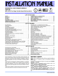
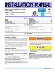
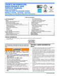
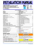
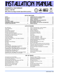
1
246815-YTG-D-0108
DESCRIPTION
These Category IV, highly efficient, compact, condensing
type furnaces are designed for residential and commercial
installations in a basement, closet, alcove, recreation room or
garage where the ambient temperature is above 32°F, or
higher. They may be either side wall or thru-roof vented using
approved plastic type combustion air and vent piping. All
units are factory assembled, wired and tested to assure
dependable and economical installation and operation.
TECHNICAL GUIDE
WARRANTY
AFFINITY
MODELS: PC9*DH
GAS-FIRED
CONDENSING / HIGH EFFICIENCY
DOWNFLOW / HORIZONTAL
MODULATING FURNACES
WITH ECM MOTOR
NATURAL GAS
60 - 120 MBH INPUT
EFFICIENCY
RATING
CERTIFIED
ISO 9001
Certified Quality
Management System
Due to continuous product improvement,
specifications are subject to change without notice.
Visit us on the web at www.york.com for the most
up-to-date technical information.
Additional rating information can be found at
www.gamanet.org.
Lifetime limited warranty on both heat exchangers to the original purchaser; a 20-year limited warranty from original installation date to subsequent purchaser.
10-year warranty on the heat exchanger in commercial applications.
5-year limited parts warranty.
FEATURES
• Modulating heating operation includes:
- Modulating gas valve
- Modulating inducer operation
• Provides increased comfort level & very quiet unit operation
• Compact, easy to install, ideal height 40" cabinet.
• Blower-off delay for cooling SEER improvement.
• Easy to connect power/control wiring.
• Built-in, high level self diagnostics with fault code display.
• Low unit amp requirement for easy replacement application.
• Integrated control module for reliable, economical operation.
• High velocity filter available for easy field installation.
• May be installed as either two-pipe (direct vent) or single
pipe vent (using indoor combustion air)
• Top intake & vent connection allows installation in narrow
locations.
• Electronic Hot Surface Ignition saves fuel cost with
increased dependability and reliability.
• Induced combustion system with inshot main burners for
quiet, efficient operation.
• No special vent termination kit required.
• 100% shut off main gas valve for extra safety.
• ECM High-efficiency, direct drive motor with large, quiet
blower.
• 24V, 40 VA control transformer and blower relay supplied
for add-on cooling.
• Hi-tech tubular aluminized steel primary heat exchanger.
• Secondary (condensing) heat exchanger of 29-4C highgrade stainless steel.
• Timed on, adjustable off blower capability for maximum
comfort.
• Independent door removal for greater durabilty and ease
of access.
• Easy access from front of unit for cleaning, maintenance or
service.
• Protection from intake, exhaust or condensate blockage.
• Insulated blower compartment for quiet operation.
• 3-way transition facilitates fresh air piping.
FOR DISTRIBUTION USE ONLY - NOT TO BE USED AT POINT OF RETAIL SALE
246815-YTG-D-0108
22-3/4
A
7/8
T-STAT WIRING 7/8” K.O.
7/8
T-STAT WIRING 7/8” K.O.
HORIZONTAL CONDENSATE
DRAIN OPENING 1-3/4”
13-7/8
HORIZONTAL CONDENSATE
DRAIN OPENING 1-3/4”
40
HORIZONTAL CONDENSATE
DRAIN OPENING 2”
JUNCTION BOX
HOLE 7/8”
22-3/4
GAS PIPE ENTRY 1-1/2”
HORIZONTAL
CONDENSATE
DRAIN OPENING 1-3/4”
29
29
CONDENSATE DRAIN
HOLE 7/8”
JUNCTION BOX
HOLE 7/8”
22-3/4
21-5/8
21-1/4
18-1/2
18-1/2
11-3/4
7-1/2
SIDE PIPING HOLE 3-3/8”
GAS PIPE
ENTRY 1-1/2”
9-1/8
8-1/2
CONDENSATE DRAIN
HOLE 7/8”
2-1/4
22-1/4
25-3/8
26-1/2
27-1/8
30-1/8
FRONT
23-11/16
23-5/8
1-1/4
19-1/4
LEFT SIDE
RIGHT SIDE
5/8
1-1/4
5/8
D
E
B
C
20
2-1/4
23-1/4
BOTTOM IMAGE
SUPPLY END
TOP IMAGE
RETURN END
DIMENSIONS
Models
CFM
Cabinet
Size
PC9B12N060DH11
PC9B12N080DH11
PC9C16N080DH11
PC9C16N100DH11
PC9C20N100DH11
PC9D20N120DH11
1200
1200
1600
1600
2000
2000
B
B
C
C
C
D
A (in.)
17-1/2
17-1/2
21
21
21
24-1/2
B (in.)
16-1/4
16-1/4
19-3/4
19-3/4
19-3/4
23-1/4
Cabinet Dimension
C (in.)
15
15
18-1/2
18-1/2
18-1/2
22
D (in.)
1-3/4
1-3/4
2-1/8
2-1/8
2-1/8
2-1/2
E (IN.)
2-3/8
2-3/8
2-3/4
2-3/4
2-3/4
3
ELECTRICAL AND PERFORMANCE DATA
Models
Input
Max/Min
Output
Max/Min
Nominal
Airflow
Cabinet Width
AFUE
Air Temp. Rise
Maximum Input
Air Temp. Rise
Minimum Input
PC9B12N060DH11
PC9B12N080DH11
PC9C16N080DH11
PC9C16N100DH11
PC9C20N100DH11
PC9D20N120DH11
MBH
60 / 21
80 / 28
80 / 28
100 / 35
100 / 35
120 / 42
MBH
57 / 20
76 / 26
76 / 26
95 / 33
95 / 33
115 / 39
CFM
1200
1200
1600
1600
2000
2000
In.
17-1/2
17-1/2
21
21
21
24-1/2
%
95.0
95.0
95.0
95.0
95.0
95.0
°F
40 - 70
40 - 70
40 - 70
40 - 70
40 - 70
40 - 70
°F
20 - 50
20 - 50
20 - 50
20 - 50
20 - 50
20 - 50
Models
Max. Outlet
Air Temp.
Blower
Blower
Size
Total
Unit
In.
11 x 8
11 x 8
11 x 10
11 x 10
11 x 11
11 x 11
Amps
9
9
12
12
14
14
Power Supply
(Voltage-PH-Hz
PC9B12N060DH11
PC9B12N080DH11
PC9C16N080DH11
PC9C16N100DH11
PC9C20N100DH11
PC9D20N120DH11
°F
170
170
170
170
170
170
Approximate
Operating
Weight
136
143
159
163
165
182
115-1-60
115-1-60
115-1-60
115-1-60
115-1-60
115-1-60
HP
1/2
1/2
3/4
3/4
1
1
Amps
7.7
7.7
9.6
9.6
12.8
12.8
Max.
Min. Wire Size
Over-current (awg) @ 75 ft.
Protect
One Way
20
20
20
20
20
20
14
14
14
14
12
12
Annual Fuel Utilization Efficiency (AFUE) numbers are determined in accordance with DOE Test procedures.
Wire size and over current protection must comply with the National Electrical Code (NFPA-70-latest edition) and all local codes.
The furnace shall be installed so that the electrical components are protected from water.
2
Unitary Products Group
246815-YTG-D-0108
AIR FLOW DATA
HIGH / LOW SPEED COOLING AND HEAT PUMP CFM
PC9B12N060DH11
PC9B12N080DH11
CFM
CFM
JUMPER SETTINGS
High
Low
High
Low
COOL Tap
ADJ Tap
1330
900
1310
890
A
B
1130
800
1100
740
B
B
1220
850
1220
830
A
A
1040
730
1000
670
B
A
1120
770
1090
720
A
C
920
650
900
610
C
B
950
660
880
610
B
C
740
540
680
510
D
B
860
610
810
580
C
A
690
540
630
500
D
A
790
570
730
530
C
C
530
590
500
D
C
630
PC9C16N080DH11
PC9C16N100DH11
PC9C20N100DH11
CFM
CFM
JUMPER SETTINGS
High
Low
High
Low
COOL Tap
ADJ Tap
1660
1110
2210
1480
A
B
1550
1050
1780
1180
B
B
1610
1070
2040
1350
A
A
1440
960
1620
1050
B
A
1470
990
1840
1250
A
C
1370
920
1560
1010
C
B
1290
850
1470
940
B
C
1130
790
1370
890
D
B
1230
850
1460
930
C
A
1050
720
1250
790
D
A
1110
760
1310
810
C
C
950
660
1090
690
D
C
PC9D20N120DH11
CFM
JUMPER SETTINGS
High
Low
COOL Tap
ADJ Tap
2280
1510
A
B
1860
1190
B
B
2090
1370
A
A
1630
1060
B
A
1880
1250
A
C
1620
1030
C
B
1500
960
B
C
1410
880
D
B
1490
920
C
A
1290
790
D
A
1360
840
C
C
1140
690
D
C
All CFM’s are shown at 0.5” w.c. external static pressure.These units have variable speed motors that automatically adjust to provide constant CFM from 0.0” to 0.6” w.c.
static pressure. From 0.6” to 1.0” static pressure, CFM is reduced by 2% per 0.1” increase in static. Operation on duct systems with greater than 1.0” w.c. external static
pressure is not recommended.
NOTE: At some settings, LOW COOL airflow may be lower that what is required to operate an airflow switch on certain models of electronic air cleaners. Consult the
instructions for the electronic air cleaner for further details.
NOTES:
1. Airflow expressed in standard cubic feet per minute (CFM).
Unitary Products Group
3
246815-YTG-D-0108
FILTER PERFORMANCE
FILTER SIZES
The airflow capacity data published in the “Blower Performance” table listed above represents blower performance
WITHOUT filters. To determine the approximate blower performance of the system, apply the filter drop value for the filter being used or select an appropriate value from the “Filter
Performance” table shown.
Cabinet
Size
Top Return
Filter in
1200
B
(2) 14 x 20
1600
C
(2) 14 x 20
2000
C
(2) 14 x 20
2000
D
(2) 14 x 20
CFM
NOTE: The filter pressure drop values in the “Filter Performance” table shown are typical values for the type of filter
listed and should only be used as a guideline. Actual pressure drop ratings for each filter type vary between filter manufacturer.
NOTE: All filters must be high velocity cleanable type.
FILTER PERFORMANCE - PRESSURE DROP INCHES W.C. AND (KPA)
Filter Type
Minimum
Opening Size
Airflow Range
CFM
in
Disposable
Washable Fiber
Pleated
In W.C.
In W.C.
In W.C.
2
0 - 750
230
0.01
0.01
0.15
751 - 1000
330
0.05
0.05
0.20
1001 - 1250
330
0.10
0.10
0.20
1251 - 1500
330
0.10
0.10
0.25
1501 - 1750
380
0.15
0.14
0.30
1751 - 2000
380
0.19
0.18
0.30
2001 & Above
463
0.19
0.18
0.30
APPLYING FILTER PRESSURE DROP TO
DETERMINE SYSTEM AIRFLOW
3.
To determine the approximate airflow of the unit with a filter in
place, follow the steps below:
1. Select the filter type.
2. Determine the External System Static Pressure (ESP)
without the filter.
Select a filter pressure drop from the table based upon
the number of return air openings or return air opening
size and add to the ESP from Step 2 to determine the
total system static.
If total system static matches a ESP value in the airflow table
(i.e. 0.20, 0.60, etc,) the system airflow corresponds to the
intersection of the ESP column and Model/Blower Speed row.
UNIT CLEARANCES TO COMBUSTIBLES
Top
Front
Rear
Flue
Floor/Bottom
In.
In.
In.
In.
In.
In.
In.
Downflow
1
3
0
0
0
0
1*
Yes
Horizontal
0
3
0
1
1
0
0
Yes
Application
Left Side Right Side
Closet
Attic
Line
Contact
Yes
Yes
NA
Yes
Yes
Yes†
Alcove
* Combustible floor base or air conditioning coil required for use on combustible floor.
† Line contact only permitted between lines formed by the intersection of the rear panel and side panel (top in horizontal position) of the furnace jacket and building joists, studs or framing.
4
Unitary Products Group
246815-YTG-D-0108
For additional connection diagrams for all UPG equipment refer to “Line Voltage System Wiring” document available on-line at
www.upgnet.com in the Product Catalog Section.
AC 26A
Two Stage Air Conditioner – Variable Speed Modulating Furnace
ID MODELS
PC9
FC9C
THERMOSTAT
THERMOSTAT
*DN22U00124
*PP32U70124
FL9C
VARIABLE SPEED
MODULATING
FURNACE
VARIABLE SPEED
MODULATING
FURNACE CONTROL
TWO STAGE
AIR
CONDITIONER
1
C
24 – Volt Common
C
24 – Volt Common
C
24 – Volt Common
C
24 – Volt Common
Y1
First Stage Compressor
Y1
First Stage Compressor
Y1
Single Stage Compressor
Y1
First Stage Compressor
R
24 – Volt Hot
(Heat XFMR)
R
24 – Volt Hot
(Heat XFMR)
R
24 – Volt Hot
R
24 – Volt Hot
G
Fan
G
Fan
G
Fan
E/W1
First Stage Heat
E/W1
Emergency Heat
W
Modulating Heat
W2
Second Stage Heat
AUX
Auxiliary Heat
R
24 – Volt Hot
(Cool XFMR)
R
24 – Volt Hot
(Cool XFMR)
Y2
Second Stage
Compressor
Y2
Second Stage
Compressor
Y/Y2
Second or Full
Stage Compressor
Y2
Second Stage
Compressor
2
2
External Humidistat
(Optional)
Open on Humidity Rise
External Humidistat
(Optional)
Open on Humidity Rise
HUM
DehumidificationOpen on Humidity Rise
24VAC Humidifier
(Optional)
Connection of the “C”
Connection of the “C”
terminal, 24-volt common terminal, 24-Volt common
is optional when used with is optional when used with
batteries
batteries
Thermostat Installer Setup Thermostat Installer Setup
1-System Type-must
0170-System Type-must
be set to 6-2 Heat/2 Cool be set to 8-2 Heat/2 Cool
Multistage Conventional Multistage Conventional
Move HUMIDISTAT
jumper to “YES”
if humidistat is to be used.
Thermostat Installer Setup
15-Compressor Protection
-must be set to 5
2
Part Number:
S1-2HU16700124
Part Numbers:
SAP = Legacy
171334 = 031-09153
1
Thermostat Chart -
Unitary Products Group
5
246815-YTG-D-0108
AC 26B
Two Stage Air Conditioner – Variable Speed Modulating Furnace
ID MODELS
PC9
THERMOSTAT
THERMOSTAT
*DN22C00124
*DP22U70124
FC9C
FL9C
VARIABLE SPEED
MODULATING
FURNACE
VARIABLE SPEED
MODULATING
FURNACE CONTROL
TWO STAGE
AIR
CONDITIONER
1
C
24 – Volt Common
C
24 – Volt Common
C
24 – Volt Common
C
24 – Volt Common
Y
First Stage Compressor
Y1
First Stage Compressor
Y1
Single Stage Compressor
Y1
First Stage Compressor
R
24 – Volt Hot
R
24 – Volt Hot
R
24 – Volt Hot
R
24 – Volt Hot
G
Fan
G
Fan
G
Fan
W
First Stage Heat
E/W1
First Stage Heat
W
Modulating Heat
W2
Second Stage Heat
W2
Second Stage Heat
Y/Y2
Second or Full
Stage Compressor
Y2
Second Stage
Compressor
Y2
Second Stage
Compressor
Y2
Second Stage
Compressor
2
2
External Humidistat
(Optional)
Open on Humidity Rise
External Humidistat
(Optional)
Open on Humidity Rise
HUM
DehumidificationOpen on Humidity Rise
24VAC Humidifier
(Optional)
Connection of the “C” Step 1 of Thermostat User
terminal, 24-Volt common Configuration Menu must
be set to MS 2
is optional when used with
batteries
Connection of the “C”
terminal, 24-Volt common
is optional when used with
batteries
2
Part Number:
S1-2HU16700124
Move HUMIDISTAT
jumper to “YES”
if humidistat is to be used.
Part Numbers:
SAP = Legacy
171334 = 031-09153
1
Thermostat Chart -
6
Unitary Products Group
246815-YTG-D-0108
AC 26C
Two Stage Air Conditioner – Variable Speed Modulating Furnace
ID MODELS
PC9
FC9C
FL9C
THERMOSTAT
VARIABLE SPEED
MODULATING
FURNACE
*PP32U71124
*PP32U72124
VARIABLE SPEED
MODULATING
FURNACE CONTROL
TWO STAGE
AIR
CONDITIONER
1
C
24 – Volt Common
C
24 – Volt Common
C
24 – Volt Common
Y1
First Stage Compressor
Y1
Single Stage Compressor
Y1
First Stage Compressor
R
24 – Volt Hot
R
24 – Volt Hot
R
24 – Volt Hot
G
Fan
G
Fan
Comfort Alert Interface
(two pin connector)
E/W1
First Stage Heat
W
Modulating Heat
W2
Second Stage Heat
Y/Y2
Second or Full
Stage Compressor
L
Malfunction Light
Y2
Second Stage
Compressor
Y2
Second Stage
Compressor
HUM
DehumidificationOpen on Humidity Rise
DHM
Dehumidification
HM
Humidistat
Step 1 of Thermostat User
Configuration Menu must
be set to MLTISTG
Step 16 of Thermostat
Installer Table Menu
must be set to ON to use
Comfort Alert Features
Only applies to
*PP32U72124
E2/P Switch must be in the
E2 position
24VAC Humidifer
(Optional)
Move HUMIDISTAT
jumper to “YES”
if humidistat is to be used.
Part Numbers:
SAP = Legacy
171334 = 031-09153
1
Optional Harness
Thermostat Chart -
Unitary Products Group
7
246815-YTG-D-0108
HP 28A
Two Stage Heat Pump – Variable Speed Modulating Furnace (With Hot Heat Pump Operation)
ID MODELS
OD MODELS
PC9
YZE
FC9C
YZH
FL9C
THERMOSTAT
H*5
H*8
VARIABLE SPEED
MODULATING
FURNACE
*PP32U71124
*PP32U72124
VARIABLE SPEED
MODULATING
FURNACE CONTROL
TWO STAGE
HEAT PUMP
YORKGUARD VI
CONTROL
2
C
24 – Volt Common
C
24 – Volt Common
C
24 – Volt Common
Y1
First Stage Compressor
Y1
Single Stage Compressor
Y1
Single Stage Compressor
R
24 – Volt Hot
R
24 – Volt Hot
R
24 – Volt Hot
G
Fan
G
Fan
W
Modulating Heat
W1 OUT
First Stage Heat
W2
Second Stage Aux. Heat
W2 OUT
Second Stage Heat
Y/Y2
Second or Full
Stage Compressor
Y2 OUT
Second Stage Compressor
O
Reversing Valve
Energized in Cool
O
Reversing Valve
Energized in Cool
L
Malfunction Light
X/L
Malfunction Light
Y2
Second Stage Compressor
Y2
Second Stage Compressor
E/W1
First Stage Aux. Heat
W
Auxiliary Heat
HUM
DehumidificationOpen on Humidity Rise
DHM
Dehumidistat
HM
Humidistat
Step 1 of the Thermostat
Installer Table must be
set to Heat Pump
Step 2 of the Thermostat
Installer Table must be
set to 2
Step 5 of Thermostat User
Configuration Menu must
be set to “ON” for
Dehumidification
E2/P Switch must be in the
E2 position
1
Bonnet Sensor
(Optional)
24VAC Humidifier
(Optional)
Move HUMIDISTAT
jumper to “YES”
if humidistat is to be used.
Part Numbers:
SAP = Legacy
171334 = 031-09153
BSG
Bonnet Sensor
BS
Bonnet Sensor
Change FFuel jumper
on the heat pump control
to “ON”
Change Hot Heat Pump
jumper on the heat pump
control to “ON”
2
Part Numbers:
SAP = Legacy
126768 = 031-09137
18395 = 031-01996
340512 = 031-09178
1
Thermostat Chart -
8
Unitary Products Group
246815-YTG-D-0108
HP 28C
Two Stage Heat Pump – Variable Speed Modulating Furnace (With Hot Heat Pump Operation)
ID MODELS
THERMOSTAT
THERMOSTAT
*PP32U70124
*DN22H00124
*DP22U70124
OD MODELS
PC9
YZE
FC9C
FL9C
YZH
H*5
H*8
VARIABLE SPEED
MODULATING
FURNACE
VARIABLE SPEED
MODULATING
FURNACE CONTROL
TWO STAGE
HEAT PUMP
YORKGUARD VI
CONTROL
2
C
24 – Volt Common
C
24 – Volt Common
C
24 – Volt Common
C
24 – Volt Common
Y
First Stage Compressor
Y1
First Stage Compressor
Y1
Single Stage Compressor
Y1
Single Stage Compressor
R
24 – Volt Hot
(Heat XFMR)
R
24 – Volt Hot
R
24 – Volt Hot
R
24 – Volt Hot
G
Fan
G
Fan
G
Fan
E
Emergency Heat
W
Modulating Heat
W1 OUT
First Stage Heat
W2
Second Stage Aux. Heat
RC
24 – Volt Hot
(Cool XFMR)
W2 OUT
Second Stage Heat
Y/Y2
Second or Full
Stage Compressor
Y2 OUT
Second Stage Compressor
O/B
Reversing Valve
O
Reversing Valve
Energized in Cool
O
Reversing Valve
Energized in Cool
L
Malfunction Light
L
Malfunction Light
X/L
Malfunction Light
Y2
Y2
Second Stage CompressorSecond Stage Compressor
AUX
Auxiliary Heat
Y2
Second Stage Compressor
E/W1
First Stage Aux. Heat
3
External Humidistat
(Optional)
Open on Humidity Rise
Thermostat Installer Setup Step 1 of Thermostat
0170-System TypeInstaller/Configuration
must be set to 12
Menu must be set to “HP2”
Selection of GAS/ELEC
3 Heat/2 Heat Pump
Thermostat Installer Setup switch on thermostat
0190-Changeover Valvenot necessary
must be set to 0
O/B terminal
Energized in Cooling
Thermostat Installer Setup
0200-Backup Heat Sourcemust be set to 1
Heat Pump Backup Heat
Source is Fossil Fuel
Thermostat Installer Setup
0210-External Fossil Fuel
Kit- must be set to 1
Heat Pump Control
is Controlling Heat Pump
Backup Heat
1
W
Auxiliary Heat
HUM
DehumidificationOpen on Humidity Rise
Bonnet Sensor
(Optional)
Move HUMIDISTAT
jumper to “YES”
if humidistat is to be used.
Part Numbers:
SAP = Legacy
171334 = 031-09153
BSG
Bonnet Sensor
BS
Bonnet Sensor
Change FFuel jumper
on the heat pump control
to “ON”
Change Hot Heat Pump
jumper on the heat pump
control to “ON”
2
Part Numbers:
SAP = Legacy
126768 = 031-09137
18395 = 031-01996
340512 = 031-09178
1
Thermostat Chart -
Unitary Products Group
9
246815-YTG-D-0108
ACCESSORIES
PROPANE (LP) CONVERSION KIT 1NP0680 - All units
This accessory conversion kit may be used to convert natural
gas (N) units for propane (LP) operation. Conversions must
be made by qualified distributor or dealer personnel.
CONCENTRIC VENT TERMINATION 1CT0302 (2")
1CT0303 (3")
CONDENSATE NEUTRALIZER KIT - 1HT0901
Neutralizer cartidge has a 1/2" plastic tube fittings for installation in the drain line. Calcium carbonate refill media is also
avaiable from the Source 1 Parts (p/n 026-30228-000).
SIDEWALL VENT TERMINATION 1HT0901 (3")
1HT0902 (2")
For use on sidewall, two-pipe installations only. Provide a
more attractive termination for locations where the terminal is
visable on the side of the home.
10
COMBUSTIBLE FLOOR BASE 1CB0317 - 17 1/2” Cabinet
1CB0321 - 21” Cabinet
1CB0324 - 24-1/2” Cabinet
COIL TRANSITION 1TK0917 - 17 1/2” Cabinet
1TK0921 - 21” Cabinet
1TK0924 - 24-1/2” Cabinet
Required in downflow applications when using G*FD series
coils.
ROOM THERMOSTATS - A wide selection of compatible
thermosets are available to provide optimum performance
and features for any installation.
1H/1C, manual change-over electronic non-programmable
thermostat.
1H/1C, auto/manual changeover, electronic programmable,
deluxe 7-day, thermostat.
1H/1C, auto/manual changeover, electronic programmable.
* For the most current accessory information, refer to the
price book or consult factory.
Unitary Products Group
246815-YTG-D-0108
NOTES
Unitary Products Group
11
NOTES
Subject to change without notice. Printed in U.S.A.
Copyright © by Unitary Products Group. 2008. All rights reserved.
Unitary
Products
Group
246815-YTG-D-0108
Supersedes: 246815-YTG-C-0606
5005
York
Drive
Norman
OK
73069