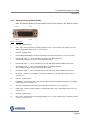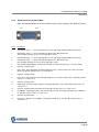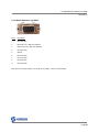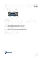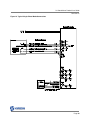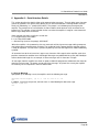
1
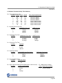
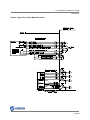
Varedan Technologies
LA Series
Stand-Alone Linear Amplifiers
Product User Guide
Revision A10
LA Stand-Alone Product User Guide
Record of Revisions
Rev
Date
Valid For
Description
A1
07/20/2011
All units
Initial release
A2
10/15/2011
All units
Revise part numbering
A3
11/11/11
All units
Add connection drawing
A4
6/1/2012
All units
Correct mating CPC part numbers
A5
6/18/2012
All units
Add J8 Male pinout
A6
7/27/2012
4016-RC
Add optical isolation for new front panel
A7
10/11/12
All units
Add 800W version
A8
08/11/14
All units
Fix limit - opto input drawing
A9
10/24/14
All units
Revise Appendix A
A10
11/14/14
All units
Add e and f commands, update LA525 settings
A11
11/18/14
All units
Autobalance update, connector updates
A12
12/23/14
All units
Update opto section
Page 2
LA Stand-Alone Product User Guide
Revision A7
Technical changes to improve performance may be made at any time without notice!
All rights reserved. No part of this work may be reproduced in any form without written permission from
Varedan Technologies.
Page 3
LA Stand-Alone Product User Guide
Revision A7
Contents
1 Introduction .......................................................................................................................................... 6
1.1
Model Numbering ............................................................................................................................. 7
1.2
Specifications 200W, 400W, 500W ................................................................................................. 7
1.3
Specifications 800W ......................................................................................................................... 8
1.4
Safety Information ............................................................................................................................ 9
1.4.1
Grounding ..................................................................................................................................... 9
1.4.2
Hazardous Voltage Information .................................................................................................... 9
2 System Installation ............................................................................................................................. 10
2.1
Mechanical Dimensions ................................................................................................................. 10
2.1.1
200W, 400W, 500W Case Dimensions...................................................................................... 10
2.1.2
800W Case Dimensions ............................................................................................................. 11
2.2
Selecting a mounting area.............................................................................................................. 12
2.3
Front Panel ..................................................................................................................................... 13
................................................................................................................................................................. 13
2.3.1
AC Input ...................................................................................................................................... 14
2.3.1.1
Changing the AC input configuration ...................................................................................... 14
2.4
Interface Connections .................................................................................................................... 15
2.4.1
Motor Connector (J1) CPC-14 .................................................................................................... 15
2.4.2
USB Connector (J2) USB B........................................................................................................ 15
2.4.3
Command B+ Input BNC (J4)..................................................................................................... 15
2.4.4
Command A+ Input BNC (J5)..................................................................................................... 15
2.4.5
Enable Input BNC (J6) ................................................................................................................ 15
2.4.6
Fault Output BNC (J7) ................................................................................................................ 15
2.4.7
Signal Connector Electrical Interface.......................................................................................... 16
2.4.7.1
J8 & J9 Electrical Interface, Optically Isolated ....................................................................... 16
2.4.7.2
J8 & J9 Electrical Interface, Non-isolated ............................................................................... 17
2.4.8
Signal Connector (J8) DB-15 Female......................................................................................... 18
2.4.9
Signal Connector (J8) DB-15 Male ............................................................................................. 19
2.4.10 RS232 Connector (J3) DB-9F..................................................................................................... 20
2.4.11 Auxiliary I/O Connector (J9) DB-9M............................................................................................ 21
2.4.12 7-Segment Display...................................................................................................................... 22
3 Establishing Communications............................................................................................................ 24
3.1
RS232 Serial Interface ................................................................................................................... 24
3.2
USB Interface ................................................................................................................................. 24
3.3
Serial Commands........................................................................................................................... 25
3.3.1
A – Alarm Reset.......................................................................................................................... 25
3.3.2
B – AutoBalance ......................................................................................................................... 25
3.3.3
E – Enable Status ....................................................................................................................... 25
3.3.4
e - Enable Level .......................................................................................................................... 25
3.3.5
F – Factory Defaults.................................................................................................................... 25
3.3.6
f - Fault Output Level .................................................................................................................. 25
3.3.7
H – Help ...................................................................................................................................... 25
3.3.8
L – List all parameters ................................................................................................................ 25
3.3.9
M – Mode .................................................................................................................................... 26
3.3.10 R – Reset .................................................................................................................................... 26
3.3.11 S – Save Parameters.................................................................................................................. 26
3.3.12 Y – Display Fault History............................................................................................................. 26
3.3.13 YC – Clear Fault History ............................................................................................................. 26
3.3.14 YS – Display SOA Fault History.................................................................................................. 26
Page 4
LA Stand-Alone Product User Guide
Revision A7
4 Serial Parameter Settings .................................................................................................................. 27
4.1
P – Parameter Command .............................................................................................................. 27
4.2
Software Parameter Setting Table Summary................................................................................. 28
5 Troubleshooting ................................................................................................................................. 31
5.1
Autobalance.................................................................................................................................... 31
6 Appendix A – Serial Interface Details................................................................................................. 32
6.1
Sign on Message............................................................................................................................ 32
6.2
Alarm Messages............................................................................................................................. 33
6.3
Autobalance Messages .................................................................................................................. 33
6.4
Enable Status Messages................................................................................................................ 33
6.5
Factory Default Message................................................................................................................ 34
6.6
Help Messages............................................................................................................................... 34
6.7
List Messages ................................................................................................................................ 35
6.8
Mode Command Messages ........................................................................................................... 35
6.9
Save Parameters Message ............................................................................................................ 35
6.10
Fault History Messages .............................................................................................................. 36
6.11
Clear Fault History Message....................................................................................................... 36
6.12
SOA Fault History Messages...................................................................................................... 37
7 Appendix B – Firmware Updates ....................................................................................................... 38
8 Sales and Service .............................................................................................................................. 39
Page 5
LA Stand-Alone Product User Guide
Revision A7
1 Introduction
The LA Series Stand-Alone linear amplifier system is an AC line powered unit based on the LA series
current-mode linear amplifiers.
Some of the key features of this system:
Available in 4 power levels
Available in single/two-phase or 3-phase models
Commonly available front panel connectors for easy wiring
Single phase 110 or 220 VAC input is only power required for operation
All required power supplies are contained in the box
Factory configurable transformer for various bus voltage options
Front panel status indicator shows amplifier status
Integrated fans provide sufficient cooling for most applications
USB or RS-232 communication capability
Flexible mounting options for bottom or side mounting
Simple setup and operation
Since the Stand Alone contains a LA amplifier module, we recommend referring to the LA Series
Technical Reference manual for the modules as well. That document is available on our website.
Page 6
LA Stand-Alone Product User Guide
Revision A7
Model Numbering
The LA Series Stand-Alone Linear Amplifier System is available in various power options and in either
single-phase or 3-phase models.
Model Number Breakdown: LA-415-SA-T
Linear Amplifier
Power Level (see table)
Stand Alone Package
S=Single Phase, T= 3 phase
1.1 Specifications 200W, 400W, 500W
Parameter
Output Phases
LA-210-SA-S LA-210-SA-T LA-415-SA-S LA-415-SA-T LA-525-SA-S LA-525-SA-T
1 or 2
3
1 or 2
3
1 or 2
3
Peak Output Current
10A
15A
25A
Continuous Output Current
2.5A
5A
10A
Peak Output Power (25°C)
400W
1200W
1500W
Continuous Power Dissipation (25°C)
200W
400W
500W
Weight
22.0lbs
Size - Height
7.87 in.
Size - Length x Width
12.17 in. x 6.28 in.
Motor Bus Voltage – Bipolar
+/-56VDC (Contact factory for other transformer choices)
Max. Heat Sink Temperature
70°C
Current Loop Bandwidth*
Operating Modes
up to 10kHz
Sinusoidal (w/ external commutation) / Trapezoidal
Absolute Overcurrent Trip Time
Hall Sensor Supply (+5 Ext.)
Command Signal (A and B inputs)
Power Requirements
Fuse
50ms
+5V @ 100mA max.
+/-10V Single-Ended, +/-20V Differential
120VAC, 10A or 230VAC, 5A
8A Slow Blow
10A Slow Blow
Notes: 1 - Single-phase models can drive 2 motor coils using ½ the bus voltage by connecting one side of
the motor coil to the phase output and the other to ground.
Page 7
LA Stand-Alone Product User Guide
Revision A7
1.2 Specifications 800W
Parameter
Output Phases
LA-830-SA-S
LA-830-SA-T
1 or 2
3
Peak Output Current
30A
Continuous Output Current
15A
Peak Output Power (25°C)
1500W
Continuous Power Dissipation (25°C)
800W
Weight
26.0lbs
Size - Height
7.93 in.
Size - Length x Width
17.70 in. x 8.75 in.
Motor Bus Voltage – Bipolar
+/-56VDC (Contact factory for other transformer choices)
Max. Heat Sink Temperature
70°C
Current Loop Bandwidth*
Operating Modes
Absolute Overcurrent Trip Time
Hall Sensor Supply (+5 Ext.)
Command Signal (A and B inputs)
Power Requirements
up to 10kHz
Sinusoidal (w/ external commutation) / Trapezoidal
50ms
+5V @ 100mA max.
+/-10V Single-Ended, +/-20V Differential
120VAC, 15A or 230VAC, 7.5A
Page 8
LA Stand-Alone Product User Guide
Revision A7
1.3 Safety Information
Read this information before operating this system.
1.3.1
Grounding
The AC power connection to the box must have a connection to ground.
CAUTION
The LA StandAlone must be plugged into a properly grounded AC outlet.
Failure to provide this ground could result in a fatal electric shock.
Verify ground continuity to all metal pieces on the system.
Metal components bolted only to granite may not be grounded. Black anodized and
painted surfaces are not conductive.
1.3.2
Hazardous Voltage Information
CAUTION
Hazardous voltages are present at the motor output terminals and within the sheet
metal enclosure. Disconnect the AC power before plugging / unplugging any
connections or before servicing or disassembling the enclosure.
Page 9
LA Stand-Alone Product User Guide
Revision A7
2 System Installation
2.1 Mechanical Dimensions
2.1.1
200W, 400W, 500W Case Dimensions
Figure 1: LA StandAlone Dimensions for 200W, 400W and 500W units
Page 10
LA Stand-Alone Product User Guide
Revision A7
2.1.2
800W Case Dimensions
A
A
0.21
17.28
4.03
7.93
A
A
1.94
8.75
17.70
1.22
17.28
A
Notes:
A: 0.2in x 0.313in Slot for UNC 10-32 Screws (8 places)
1) All dimensions in inches
A
6.22
A
A
0.21
Figure 2: LA StandAlone Dimensions for 800W units
Page 11
LA Stand-Alone Product User Guide
Revision A7
2.2 Selecting a mounting area
The unit should be mounted in a solid, clean, dry location with adequate ventilation.
Avoid mounting areas that:
Obstruct the intake or exhaust of the internal forced air cooling.
Allow dust, debris to enter and contaminate the cooling capability of the drive.
Have humidity above 80% or are susceptible to moisture or coolant.
Are prone to corrosive or flammable materials.
Have an ambient temperature higher than 85°F (30°C).
Vibrate, are susceptible to vibration or that could transmit the cooling fan vibration to sensitive
test equipment.
Note:
The StandAlone’s allowable power output is limited by the amplifier heatsink temperature. Any
reduction in cooling capability will be directly proportional to a reduction in performance.
Page 12
LA Stand-Alone Product User Guide
Revision A7
2.3 Front Panel
AC Power Switch
ON / OFF
AC Input
Module
AC Input Selector Panel
115 / 230VAC
Fan Exhaust / Exit
14 Pin CPC
Motor Connector
USB Connector
Reset Switch
LED Display
Signal Connector
RS232 Interface
Aux. I/O Interface
BNC Connectors
Page 13
LA Stand-Alone Product User Guide
Revision A7
2.3.1
AC Input
The LA Stand-Alone amplifier can accept AC input voltages of 100 – 120 and 208 - 240VAC at 47 – 63Hz.
Note that the Stand-Alone amplifier utilizes an unregulated linear power supply. Therefore a higher AC
input (for a given range) will provide a higher voltage to the spindle and allow the spindle to reach higher
velocities.
The AC Inlet should be configured per the table below.
Fuse /
Input AC Voltage Ranges
Fuse Block Value in Window
(47-63 Hz)
Fuse Value
115V / 230V
Input Minimum
Input Maximum
8A
115
100
120
4A
230
208
240
Figure 3: Suggested Fusing for AC Input
2.3.1.1 Changing the AC input configuration
1. Remove power from the AC Inlet
2. Use a flat tipped screwdriver to open the window that covers the red voltage value.
3. Use the screw driver to remove the fuse block.
4. Use the table above to determine the correct fuse value.
5. Reinstall the fuse module such that the correct voltage value will show through the window.
6. Close the window.
Figure 4: Fuse block removal from the AC inlet
Page 14
LA Stand-Alone Product User Guide
Revision A7
2.4 Interface Connections
2.4.1
Pin 3
Motor Connector (J1) CPC-14
Pin 1
Pin 7
Pin 4
Pin 11
Pin 8
Pin 12
Pin 14
2.4.2
2.4.3
2.4.4
2.4.5
2.4.6
Pin #
Description
1
6
8
14
Motor Phase C or Single-Phase Motor Phase B or Single-Phase +
Motor Phase A (not used for Single-Phase)
GND
Mate: Varedan 4006-62
Includes the following:
Tyco: 206044-1 Tyco: 66359-2x4 Tyco:206070-1
USB Connector (J2) USB B
Command B+ Input BNC (J4)
Command A+ Input BNC (J5)
Enable Input BNC (J6)
Fault Output BNC (J7)
Pin #
Description
1
2
3
4
+5vdc
USB USB +
GND
Pin #
Description
1
Shell
Command B+ Input (Same as J8-3)
GND
Pin #
Description
1
Shell
Command A+ Input (Same as J8-1
GND
Pin #
Description
1
Shell
Enable Input (Same as J8-11)
GND
Pin #
Description
1
Shell
Fault Output (Same as J8-13)
GND
Page 15
LA Stand-Alone Product User Guide
Revision A7
2.4.7
Signal Connector Electrical Interface
The following drawings illustrate the electrical interface for the J8 & J9 signal connectors. Note that there
are 2 configurations available from the factory, one with optical isolation and one without. Please be sure
to use the correct drawing. Also note that J8 can be either DB15M (male) or DB15F (female).
2.4.7.1 J8 & J9 Electrical Interface, Optically Isolated
For the optically isolated version of J8, Opto Common is pin 14 and can be any voltage in the range 524vdc. Active signal inputs are low referenced to the supply providing the Opto Common voltage.
Alternatively a common ground can be provided on pin 14 and 5-24vdc can be used to activate the
individual inputs. Note that the Fault output is open collector with no internal current limiting
resistor. The user must provide an external current limiting resistor to limit current to no more
than 200mA.
Note: Pin outs are shown for DB15M connector option. Refer to 2.4.8 or 2.4.9 as appropriate.
Page 16
LA Stand-Alone Product User Guide
Revision A7
2.4.7.2 J8 & J9 Electrical Interface, Non-isolated
The following drawing shows the non-isolated interface for J8 and J9.
Note: Pin outs are shown for DB15M connector option. Refer to 2.4.8 or 2.4.9 as appropriate
Page 17
LA Stand-Alone Product User Guide
Revision A7
2.4.8
Signal Connector (J8) DB-15 Female
Note: Two different genders of J8 are used. Be sure to use the correct pin out (Male or Female).
Pin 8
Pin 15
Pin 1
Pin 9
Pin #
Description
1
Common - Signal Ground
2
Limit + Input - Active high input, Internally pulled high (3.3V), set low to enable travel. Not used in Sine
Mode. For optically isolated version see section 2.4.7.1
3
Common - Signal Ground
4
Current Monitor IRMS Output - Analog current output 1V=10A (LA-210/LA-415) or 1V=3.3A (LA-525)
5
Command B - Input - +/- 10vdc command input. Only used in Differential mode
Note: Command B inputs are also used for single-phase mode
6
Command B+ Input - +/- 10vdc command input. Used in both Single Ended and Differential modes
7
Command A- Input - +/- 10vdc command input. Only used in Differential mode
Note: Command A inputs are not used in single-phase mode
8
Command A+ Input - +/- 10vdc command input. Used in both Single Ended and Differential modes
9
Reset Input - Ground to reset amplifier. Internally pulled high (3.3V). For optically isolated version see
section 2.4.7.1
10
Common - Signal Ground
11
Fault Output - High output indicates fault, low normally (no fault). Internally pulled high (5V). For optically
isolated version see section 2.4.7.1.
12
Common - Signal Ground. Fault Collector for optically isolated version. See section 2.4.7.1.
13
Enable Input - Ground to enable amplifier. Internally pulled high (3.3V). For optically isolated version see
section 2.4.7.1
14
Common - Signal Ground
15
Limit - Input - Active high input, Internally pulled high (3.3V), set low to enable travel. For optically isolated
version see section 2.4.7.1
Page 18
LA Stand-Alone Product User Guide
Revision A7
2.4.9
Signal Connector (J8) DB-15 Male
Note: Two different genders of J8 are used. Be sure to use the correct pin out (Male or Female).
Pin 1
Pin 8
Pin 9
Pin 15
Pin #
Description
1
Command A+ Input - +/- 10vdc command input. Used in both Single Ended and Differential modes
2
Command A- Input - +/- 10vdc command input. Only used in Differential mode
Note: Command A inputs are not used in single-phase mode
3
Command B+ Input - +/- 10vdc command input. Used in both Single Ended and Differential modes
4
Command B - Input - +/- 10vdc command input. Only used in Differential mode
Note: Command B inputs are also used for single-phase mode
5
Current Monitor IRMS Output - Analog current output 1V=10A (LA-210/LA-415) or 1V=3.3A (LA-525)
6
Common - Signal Ground
7
Limit + Input - Active high input, Internally pulled high (3.3V), set low to enable travel. Not used in Sine
Mode. For optically isolated version see section 2.4.7.1.
8
Common - Signal Ground
9
Limit - Input - Active high input, Internally pulled high (3.3V), set low to enable travel. For optically isolated
version see section 2.4.7.1.
10
Common - Signal Ground
11
Enable Input - Ground to enable amplifier. Internally pulled high (3.3V). For optically isolated version see
section 2.4.7.1.
12
Common - Signal Ground. Fault Collector for optically isolated version. See section 2.4.7.1.
13
Fault Output - High output indicates fault, low normally (no fault). Internally pulled high (5V). Fault Emitter
for optically isolated version see section 2.4.7.1.
14
Common - Signal Ground
15
Reset Input - Ground to reset amplifier. Internally pulled high (3.3V). For optically isolated version see
section 2.4.7.1.
Page 19
LA Stand-Alone Product User Guide
Revision A7
2.4.10 RS232 Connector (J3) DB-9F
Pin 5
Pin 9
Pin 1
Pin 6
Pin #
Description
1
No Connection
2
RS232 Receive - Data into amplifier
3
RS232 Transmit - Data from amplifier
4
No Connection
5
Ground
6
No Connection
7
No Connection
8
No Connection
9
No Connection
Note: Receive and Transmit pins are disabled if J2 (USB) is used for communication.
Page 20
LA Stand-Alone Product User Guide
Revision A7
2.4.11 Auxiliary I/O Connector (J9) DB-9M
Pin 1
Pin 6
Pin 5
Pin 9
Pin #
Description
1
Motor Temperature Switch Input - Ground to enable amplifier (switch closed). Pulled up to +5vdc.
2
Common - Use as return for Motor Temperature Switch.
3
Common - Ground
4
Hall C Input. For optically isolated version see section 2.4.7.1
5
Hall A Input. For optically isolated version see section 2.4.7.1
6
Hall B Input. For optically isolated version see section 2.4.7.1
7
+5VDC Output
8
DSP Program Input - Contact Factory for Programming Instructions.
9
Common - Ground
Note: +5VDC Output is limited to 300mA
Page 21
LA Stand-Alone Product User Guide
Revision A7
2.4.12 7-Segment Display
The 7 segment LED display on the front panel shows the status of the controller in real-time. The following
table lists the front panel LED display codes and their meaning. If multiple errors are present, the display
will cycle through all the error codes, displaying each for ½ second. Most errors can be reset by either
pressing the front panel pushbutton switch or cycling power to the unit, although some errors cannot be
fixed in the field. Please contact the factor for assistance with any errors that do not clear after a reset.
Ok, motor current enabled. This is the “normal” display when enabled.
DSP Fault – Set when the internal DSP checksum fails following reset
NVM Fault – Set when NVM checksum fails following reset. Parameter
defaults are set.
Internal +5vdc – Set when the internal +5vdc supply is out of range
Autobalance Fault – Set when autobalance can’t balance amplifier outputs.
ABS Overcurrent – Set when instantaneous overcurrent condition is detected
SOA – Set when Safe Operating Area protection detects an over power
condition.
Internal +5 vdc Reference error – Set when internal +5 reference supply is out of range
Bus Over Voltage – Set when the internal motor bus voltage is greater than +/-75 vdc.
Ok, not enabled (Output is Clamped off). This is the normal display when not enabled.
Internal +2.5 vdc Reference error – Set when internal 2.5vdc supply is out of range.
Fatal Error – Set if the DSP encounters an unidentified problem.
Page 22
LA Stand-Alone Product User Guide
Revision A7
Heatsink Over Temp – Set when the heat sink temperature is above 70 C. Remove power
and allow the unit to cool before attempting to run again.
Overcurrent – Set when amplifier detects an overcurrent condition. (“L”ow speed circuit
breaker).
Bus Under Voltage – Set when the internal motor bus voltage is less than +/-10 Vdc.
Bias error – Set when the internal bias voltage input is outside the allowable range.
(Decimal point on) Indicates an Overcurrent (“L”) trip pending
Page 23
LA Stand-Alone Product User Guide
Revision A7
3
Establishing Communications
The LA StandAlone amplifier communicates via a RS232 port or USB port at 19200 baud.
A serial communication program such as HyperTerminal can be used for communications. The standard
settings are 8 data bits, 1 stop bit, no parity and no hardware or software handshaking.
Settings Emulation = ANSIW. ASCII Setup No boxes checked, 100msec delay,
HyperTerminal Note: When changing baud rates or establishing communication for the first time use the
call\disconnect and then call\call tab prior to cycling power to the controller.
3.1 RS232 Serial Interface
The controller can communicate with a host via RS-232 using a standard three wire DTE to DTE cross
over serial cable as shown below. Note that the J3 RS-232 interface pins (2 & 3) are disabled if the USB
port is being used, but the signal pins remain active.
NOTE: Do not attempt to use RS-232 and USB at the same time. Remove the USB connector when
using RS-232.
Figure 8: Serial Data Cable Diagram
3.2 USB Interface
As an alternative to RS-232, USB can be used for communication. The connection is a standard USB
Type B connector. The easiest way to use the USB interface is to establish a virtual com port (VCP) using
the driver provided by Future Technology Devices, Inc. which can be found at
http://www.ftdichip.com/Drivers/VCP.htm
This driver allows the USB port to be configured as a COM port by the operating system. Application
software can access the USB device in the same way as it would access a standard COM port with of the
same settings.
Be sure to set the baud rate for the VCP to 19200 When an active USB cable is plugged into the USB
port, the RS-232 communication on J3 is disabled.
NOTE: Do not attempt to use RS-232 and the USB at the same time. Remove the RS-232 connector
when using USB.
Page 24
LA Stand-Alone Product User Guide
Revision A7
3.3 Serial Commands
The following commands are supported over the serial port communications interface.
3.3.1 A – Alarm Reset
This command allows viewing or resetting the alarm status. “A” with no parameter is used to read the
alarm status. “A 1” is used to reset the alarm status. Note: When an alarm is detected by the system, the
drive is immediately disabled.
3.3.2 B – AutoBalance
This command is used to invoke the autobalance algorithm. During autobalance the display will indicate
“-“ (middle bar).
3.3.3 E – Enable Status
This command is used to set/view the enable state of the drive. Note: When an alarm is detected by the
system, the drive is immediately disabled.
There are two modes of Enable operation, Software and Hardware. In Hardware mode, the drive enable
is controlled by the hardware Enable input. A low on this input Enables the drive. A high or open on this
input disables the drive. The E command only allows viewing the enable state when in “hardware” enable
mode.
Software enable mode is configured following a reset and BEFORE the hardware input is used. The
drive will come up disabled and the E command can be used to enable (E1) or disable (E0) the drive. If at
any time during software mode operation, the hardware input goes low, the drive reverts to hardware
mode as described above.
3.3.4 e - Enable Level
This command sets or views the active level for the hardware enable input. Entering e 0 sets the level to
active low. Entering e 1 sets the level to active high. Entering e without any value returns the present
setting. The factory default level is 0 (active low) to enable.
3.3.5 F – Factory Defaults
This command is used to set all the parameters to the factory defaults. Use the “S” command to save
the settings to NVM following the F command. By not automatically saving the defaults, the user can
choose to go back to the original settings (that were in the drive before the F command was used) by
resetting the drive.
3.3.6 f - Fault Output Level
This command sets or views the active level for the Fault output. Entering f 0 sets the active Fault output
to low for a fault condition. Entering f 1 sets the active Fault output high for a fault condition. Entering f
without any value returns the present setting. The factory default level is 1 (active high) for a fault
condition.
3.3.7 H – Help
This command lists a summary of commands and their function.
3.3.8 L – List all parameters
This command lists all the user settable parameters and system readings to the display. The enable and
alarm status are also shown.
Page 25
LA Stand-Alone Product User Guide
Revision A7
3.3.9 M – Mode
This command is used to view or set the commutation mode of the drive. M0 sets trapezoidal
commutation, M1 sets Sinusoidal 2 phase input commutation. The “M command can only be used to view
the commutation setting if jumpers are installed.
3.3.10 R – Reset
This command causes the drive to perform a power on reset.
3.3.11 S – Save Parameters
This command saves the user selectable parameters to NVM.
3.3.12 Y – Display Fault History
The last 8 errors from the fault history buffer are displayed. If a fault occurs while the drive is enabled, the
fault is saved into the fault history buffer. The last 8 errors are saved in NVM and recalled for display when
this command is issued. Only errors that occur while the drive is enabled are stored. This prevents
nuisance errors that commonly occur during startup/shutdown to be ignored.
3.3.13 YC – Clear Fault History
This command clears the fault history buffer in NVM. This command is useful after setting up a new
system in production to be sure any setup errors are cleared.
3.3.14 YS – Display SOA Fault History
This command displays the last saved SOA trip information from NVM. In the event of an SOA trip, all
the system parameters related to the trip are stored. This information is useful to the factory for
troubleshooting SOA events.
Page 26
LA Stand-Alone Product User Guide
Revision A7
4 Serial Parameter Settings
The user parameter settings are configured either by jumpers or via the serial interface. When jumpers
are used, the serial interface can only be used to read the jumper settings. If no jumpers are installed, the
software settings are used. If the configuration when using jumpers results in no jumpers being installed
(Sine Mode with all minimum values), place a jumper on JP1-G. This will force the drive to read and use
the jumper settings. The use of this jumper in Sine mode will not affect operation.
When no jumpers are installed, the settings are controlled from software using P values as shown
below. To use the serial interface to configure the settings, remove all jumpers and use the values as
described below for the Pn locations. Note that if any jumper is installed, all jumper settings will be read
and used for setting the parameters.
4.1 P – Parameter Command
This command is used to view or set the user parameters and RAM locations in the drive. The following
list shows software variables and their corresponding “P” access number. Be VERY careful when
changing these values, as the software does not provide for protection from improper settings. Adverse
settings may cause “undesirable” effects on the system.
The values for P0-P6 reflect the jumper settings as described above when jumpers are installed and
cannot be changed from the serial interface. When no jumpers are installed, these values can be modified
using the serial interface by changing the appropriate Pn value to configure the drive as if jumpers were
present.
P0
P1
P2
P3
P4
P5
P6
P7
Transconductance setting
Absolute Overcurrent Trip setting
Overcurrent Trip setting
Overcurrent Trip Time setting
Input Filter setting
Sine/ Hall mode setting
Current Loop Bandwidth setting
Motor Reverse setting
Note: P8-P255 are system values that should not be changed by the user.
To set a parameter value, type P followed by the address (0-6) followed by a space followed by the value
followed by <Enter> (Cr Lf). Refer to the next page for the P values and their settings.
Example: Set P1 Absolute Overcurrent Trip to 15.0 Amps.
Type: P1 1<Enter>
Drive response: 1
To view a parameter setting, type P followed by the address (0-6) followed by Enter.
Example: View the Overcurrent Trip setting:
Type: P2 <Enter>
Drive response: 1 (or whatever the present value is)
Page 27
LA Stand-Alone Product User Guide
Revision A7
4.2 Software Parameter Setting Table Summary
P0 – Transconductance value
P0 Value LA-210 LA-415 LA-525
0
0.25
0.8
1.0
1
0.5
1.0
1.5
2
0.75
1.2
2.0
3
1.0
1.5
2.5
4
0.25
0.8
1.0
5
0.5
1.0
1.5
6
0.75
1.2
2.0
7
1.0
1.5
2.5
DAC Single End/Differential
Differential (Bipolar)
Differential (Bipolar)
Differential (Bipolar)
Differential (Bipolar)
Single Ended (Unipolar)
Single Ended (Unipolar)
Single Ended (Unipolar)
Single Ended (Unipolar
P1 – Absolute Overcurrent Level
P1 Value
LA210/LA415 Trip Level
0
12 Amps
1
15Amps
2
18Amps
3
20Amps
LA525 Trip Level
15 Amps
20 Amps
25 Amps
30 Amps
P2 – Overcurrent Trip Level
P2 Value
LA210/LA415 Trip Level
0
2.0 Amps
1
3.0 Amps
2
4.0 Amps
3
5.0 Amps
LA525Trip Level
4 Amps
6 Amps
8 Amps
10 Amps
P3 – Overcurrent Trip Time
P3 Value
Trip Time
0
1.25 Sec
1
2.5 Sec
2
5.0 Sec
3
10.0 Sec
P4 – Input Filter Setting
P4 Value
LA210/LA415 Input Filter Setting
0
500 Hz
1
800 Hz
2
15 kHz
3
32 kHz
LA525Input Filter Setting
500 Hz
2,500 Hz
10,000 Hz
20,000 Hz
P5 – Sine Hall Mode Setting
P5 Value
Sine Hall Setting
0
Sine
1
Hall
P6 – Open Loop Gain Setting (fixed configuration in some versions)
P6 Value
Current Loop Bandwidth
0
Contact
1
Factory
2
For
3
Settings
P7 – Motor Reverse Setting
Value Motor Reverse Setting
0
Normal Halls Direction
1
Reverse direction
Page 28
LA Stand-Alone Product User Guide
Revision A7
Figure 9. Typical Three-Phase Mode Connections
Page 29
LA Stand-Alone Product User Guide
Revision A7
Figure 10. Typical Single-Phase Mode Connections
Page 30
LA Stand-Alone Product User Guide
Revision A7
5 Troubleshooting
5.1 Autobalance
The amplifier has a built-in algorithm for balancing the linear amplifier power stage. Normally it is not
necessary to perform this procedure as the amplifier stage is balanced at the factory. Due to the inherent
offsets of the analog circuitry in the power stage, offsets may occur in the system over time that cause
unwanted torque ripple. Offsets can be detected in open loop mode by commanding 0 current and rotating
the motor by hand and feeling for “detents”. If any significant detents are found, balancing may be
necessary.
To Autobalance the system, the following procedure is used:
1) Run the system to operating temperature.
2) Lock the motor such that no motion can be commanded by the controller when current is applied.
3) Issue a "B" command over the serial interface. Alternatively the procedure can be started by
accessing the amplifier module under the top cover and pressing the S1 reset switch for greater
than 1 second. Note: The reset switch on the front panel will not initiate Autobalance.
The middle bar on the LED display will illuminate indicating Autobalance is in progress.
4) Autobalance is now running and may take up to 1 minute to complete.
5) When the Autobalance algorithm completes successfully (“C” or “0” on display), issue a “S”
command to save the final settings in the amplifier. If this save is not performed, a power on reset
will return the balance to the pre-autobalance settings.
6) If Autobalance cannot complete, a “4” error code will be on the display. This indicates the
controller is unable to balance the motor. Reset the system and try again to Autobalance.
Autobalance errors can be due to motor movement, very low resistance (<1 ohm), severely out of
range balance in the amplifier, or other internal problems. Please contact the factory for
assistance if repeated attempts to Autobalance fail.
Page 31
LA Stand-Alone Product User Guide
Revision A7
6 Appendix A – Serial Interface Details
This section describes the details of the serial communication messages. The only white space character
used in this protocol is the Space (ASCII 0x20). All lines are terminated with a Carriage Return and Line
Feed (cr/lf) followed by a “>” prompt (ASCII 0x3E). The prompt is sent following any message by the
amplifier. The prompt line has no termination in order to allow a dumb terminal cursor to remain on the
prompt line. This provides a clear indication for the user when the amplifier is ready for a new command
when using a dump terminal interface.
Some common characters used in this section are:
cr = Carriage Return, ASCII 0x0D
lf = Line Feed, ASCII 0x0A
> = Greater Sign (used as the prompt), ASCII 0x3E
When the amplifier is first powered up, the user must wait until the sign on message and the prompt are
sent before normal communication can begin. The sending of the first prompt from the amplifier means it
is ready for operation. If a fault alarm is present on power up, the fault message will be shown followed by
a prompt.
All command sent to the unit must be in upper-case characters. Messages that the amplifier sends for a
particular command or condition are a fixed length. Messages are padded with the space (ASCII 0x20) to
achieve the desired length. As an example, all alarm messages are 14 characters in length.
All messages from the amplifier are shown in quotes to allow the programmer to determine the character
count for each message. The quotes are not part of the message. Any blank lines sent by the amplifier
are shown by the cr/lf sequence in the text shown below.
6.1 Sign on Message
Upon power up or following a reset, the amplifier sends the following message.
“Varedan Technologies, (c) 2007 Ver 4002-11-2.3.0-2”
“>”
In addition, if any faults are present, the fault status is show following the above message.
“Alarm = BUS UV”
“>”
Page 32
LA Stand-Alone Product User Guide
Revision A7
6.2 Alarm Messages
Sent in response to “A” command or upon detection of alarm condition. 16 possible responses, 14
characters in length.
"Alarm
"Alarm
"Alarm
"Alarm
"Alarm
"Alarm
"Alarm
"Alarm
"Alarm
"Alarm
"Alarm
"Alarm
"Alarm
"Alarm
"Alarm
"Alarm
“>”
=
=
=
=
=
=
=
=
=
=
=
=
=
=
=
=
DSP
"
NVM
"
HALLS "
AMP OT"
MOT OT"
ABS OC"
RMS OC"
BUS OV"
BUS UV"
5V REF"
15VREF"
2.5REF"
5V EXT"
AUTOBL"
SOA
"
FATAL "
6.3 Autobalance Messages
In response to the “B” command:
If Autobalance can’t run:
“Drive Must Be Enabled to use this command”
“>”
While Autobalance is active:
“-“
(Prompt is sent upon completion of Autobalance)
“>”
6.4 Enable Status Messages
In response to the “E” command:
If disabled with alarm:
“DISABLED”
cr/lf
“Alarm = BUS UV”
“>”
If disabled without alarm:
“DISABLED”
“>”
If enabled:
“ENABLED”
“>”
Page 33
LA Stand-Alone Product User Guide
Revision A7
6.5 Factory Default Message
In response to the “F” command:
"Loading Default Parameters"
“>”
6.6 Help Messages
In response to the “H” command:
“Command List”
“A<n> = Show/Reset Alarm Status”
“E<n>= Set/View Enable Status Enable=1 Disable=0”
“F = Load Factory Defaults”
“H = Help”
“L = List Parameters”
“M = View Mode”
“P Addr <data> = Set/View Parameter”
“R = Reset Drive”
“S = Save setting to NVM”
“T = SOA Trip Data”
“Y = Show Alarm History”
“YC = Clear Alarm History”
“YS = Show Saved SOA Fault Data”
cr/lf
“>”
Page 34
LA Stand-Alone Product User Guide
Revision A7
6.7 List Messages
In response to the “L” command:
“Bus+= 0 V”
“Bus-=-0 V”
“Vpha= 0 V”
“Vphb= 0 V”
“Vphc= 0 V”
“Ipha= 0.0 A”
“Iphb= 0.0 A”
“Iphc= 0.0 A”
“+15 = 15.2 V”
“-15 =-15.2 V”
“+5 = 4.9 V”
“+5Ex= 4.9 V”
“+2.5= 2.50 V”
“-2.5=-2.50 V”
“Temp= 23 C”
cr/lf
“RMS Overcurrent,JP1-A,B (Amps): Off Off”
“RMS Trip Time, JP1-C,D (Sec): On Off ”
“Absolute Overcurrent, JP1-E,F (Amps): Off On ”
“Motor Direction Setting, JP1-H: Normal”
“Sine or Hall Mode, JP2-A: Sine”
“Input Filter Setting, JP2-B,C (kHz): On On ”
“Transconductance Ratio, JP2-D,E: Off Off”
“Input Differential or Single Ended, JP2-F : Diff”
cr/lf
“DISABLED”
cr/lf
“Alarm = BUS UV”
“>”
Note that this is an example message. The actual message data depends on the values and status of the
amplifier. If the amplifier is enabled, “ENABLED” is shown instead of “DISABLED”. The alarm message
follows the alarm message formats as described earlier.
6.8 Mode Command Messages
In response to the “M” command, the amplifier responds with the following, depending on the jumper
settings or the user setting for mode:
“Sine Current Mode”
“>”
“Trap Current Mode”
“>”
6.9 Save Parameters Message
In response to the “S” command:
“Saving Parameter”
“>”
Page 35
LA Stand-Alone Product User Guide
Revision A7
6.10
Fault History Messages
In response to the “Y” command:
cr/lf
“Alarm History (Last to First)”
cr/lf
“Alarm = BUS UV”
cr/lf
“Alarm = 15VREF”
cr/lf
“Alarm = 15VREF”
cr/lf
“Alarm = BUS UV”
cr/lf
“Alarm = 15VREF”
cr/lf
“Alarm = ABS OC”
cr/lf
“Alarm = BUS UV”
cr/lf
“Alarm = BUS UV”
cr/lf
“>”
Note that this is just an example fault history. Actual results may vary, but all messages follow the format
for the Alarm messages described earlier. If no history is stored, the amplifier responds with just a prompt.
6.11
Clear Fault History Message
In response to the “YC” command:
cr/lf
Alarm History Cleared
cr/lf
“>”
Page 36
LA Stand-Alone Product User Guide
Revision A7
6.12
SOA Fault History Messages
In response to the “YS” command:
cr/lf
“Saved SOA History”
cr/lf
“Cnts= 0”
“MaxP= 0 W”
“ActP= 0 W”
“Bus+= 0.0 V”
“Bus-=-0.0 V”
“Vpha= 0.0 V”
“Vphb= 0.0 V”
“Vphc= 0.0 V”
“Ipha= 0.0 A”
“Iphb= 0.0 A”
“Iphc= 0.0 A”
“Temp= 0 C”
cr/lf
“>”
Note that this is an example message. Actual results will be displayed in the event of an actual SOA trip.
Page 37
LA Stand-Alone Product User Guide
Revision A7
7
Appendix B – Firmware Updates
It may become necessary to update the firmware in the controller if a new release of code becomes
available, or if additional features are added. Updates are easily done in the field using a personal
computer with a USB or RS-232 serial interface port and a small application program that sends the
updated code to the controller from the host PC. The controller contains a built-in boot loader that updates
the firmware via the RS-232 or USB interface. This boot loader becomes active when the DSP detects J9
pin 8 (DSP Program) is grounded on power up or reset. In this mode the normal serial interface is
disabled and a special programming interface is activated. Please contact the factory for more detailed
programming instructions.
Page 38
LA Stand-Alone Product User Guide
Revision A7
8 Sales and Service
Varedan Technologies
3870 Del Amo Blvd
Suite 503
Torrance, CA 90503
1-310-542-2320
www.varedan.com
[email protected]
Page 39