1
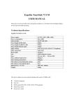
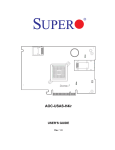
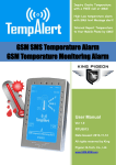
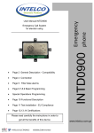
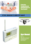
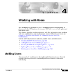
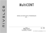
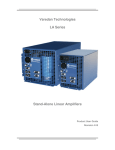
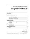
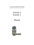
Remote switching machines
with a FREE call from your
mobile phone!
Remote inquiry the status with
a FREE Call from your mobile
phone!
Remote inquiry the Data
acquisition Value with a FREE
call from your mobile phone!
GSM Remote Switch
GSM SMS Controller Alarm User Manual
Ver 1.1
RTU5017
Date Issued: 2013-07-12
All rights reserved by King
Pigeon Hi-Tech. Co., Ltd.
www.GSM-M2M.com
GSM Remote Switch
GSM SMS Controller Alarm
Table of Contents
1. Brief Introduction ------------------------------------------------------------------------------------------------------------3
2. Safety Directions -------------------------------------------------------------------------------------------------------------3
3. Standard Packing List ------------------------------------------------------------------------------------------------------4
4. Mainly Features---------------------------------------------------------------------------------------------------------------4
5. Physical Layout and Installation Diagram----------------------------------------------------------------------------5
5.1 Control Unit physical layout-------------------------------------------------------------------------------------------------5
5.2 Interface instruction for installation--------------------------------------------------------------------------------------6
6. Programming and Operation -------------------------------------------------------------------------------------------7
6.1 Setup New Password--------------------------------------------------------------------------------------------------8
6.2 Setup Authorized number--------------------------------------------------------------------------------------------------8
6.3 Setup Digital Input Attributes----------------------------------------------------------------------------------------------10
6.4 Setup Analog input Attributes--------------------------------------------------------------------------------------11
6.5 Setup Digital Output Attributes-------------------------------------------------------------------------------------------14
6.6 Armed/Disarmed the GSM Unit---------------------------------------------------------------------------------------15
6.7 Inquiry the GSM Unit current status-------------------------------------------------------------------------------------16
6.8 Setup Automatically report attributes----------------------------------------------------------------------------------16
6.9 Inquiry the IMEI Code and firmware version-------------------------------------------------------------------------16
6.10 External AC Power Status Monitoring---------------------------------------------------------------------------------16
7. iOS App and Android Apps Instructions-----------------------------------------------------------------------------17
8. Technical specifications---------------------------------------------------------------------------------------------------17
9. Quality Warranty -------------------------------------------------------------------------------------------------------------18
10.AffixTable--Installation Schedule--------------------------------------------------------------------------------------18
This handbook has been designed as a guide to the installation and operation of RTU5017 GSM SMS Controller
Alarm.
Statements contained in the handbook are general guidelines only and in no way are designed to supersede the
instructions contained with other products.
We recommend that the advice of a registered electrician be sought before any Installation work commences.
King Pigeon Hi-Tech.Co., Ltd, its employees and distributors, accept no liability for any loss or damage including
consequential damage due to reliance on any material contained in this handbook.
King Pigeon Hi-Tech.Co., Ltd, its employees and distributors, accept no liability for GSM Network upgrading or
SIMCard upgrading due to the technology specifications contained in this handbook.
SMS Command List
SMS COMMAND
Functions & Actions
AA
To arm the Unit, in this mode, digital inputs triggered will alarm.
BB
To disarm the Unit, in this mode, digital input triggered will not alarm.
Very Important!
Please fill the
Installation
CC
To switch ON the Relay Output X and Y;
Schedule at last
DD
To switch OFF the Relay Output X and Y
Page before
EE
Inquiry the Unit Status.
programming it.
*The commands should plus Password, the format is Password+SMS Command. i.e.: if the password is 1234, then
you can send 1234AA to arm, 1234BB to disarm, the AA~EE must be Caps Lock.
King Pigeon Hi-Tech. Co., Ltd.
Page 2 of 18 Ver 1.1
File No.:RTU501710
GSM Remote Switch
GSM SMS Controller Alarm
1. Brief introduction
The GSM SMS Controller RTU5017 is a very simple programmable I/O ports (1AD, 2DIN, 2DOUT) and
cost effective GSM RTU which can be used for data acquisition, remote switching machine, temperature
monitoring, automation system and other applications.
Just dial from Authorized User number then one of the two relay output or any one of the relay output will
be switched on or off. There are no call costs, the GSM SMS Controller Alarm rejects the call from
authorized number then carries out the turn ON/OFF action.
The RTU5017 also supports interval time to report the Analog input value, Digital output status to the
authorized numbers, and also can report the value of them while the threshold of the ultra-high----high, low
---- ultra-low occurrence.
Moreover, the RTU5017 with 2 digital inputs for digital inputs, when any one of the inputs triggered, will
activate one or both of the relay outputs, in the meanwhile, the RTU5017 will send SMS Alert or dial to
authorized numbers immediately. This is very useful if you need protect your assets with low cost solution.
In one word, the GSM SMS Controller RTU5017 is the best choice for lots of applications.
2.Safety Directions
Safe Startup
Do not use GSM unit when using GSM equipment is prohibited or might bring disturbance or
danger.
Interference
All wireless equipment might interfere network signals of GSM unit and influence its
performance.
Avoid Use at Gas Station
Do not use GSM Gate Opener at a gas station. Power off GSM unit when it near fuels or
chemicals.
Power it off near Blasting Places
Please follow relevant restrictive regulations. Avoid using the device in blasting places.
King Pigeon Hi-Tech. Co., Ltd.
Page 3 of 18 Ver 1.1
File No.:RTU501710
GSM Remote Switch
GSM SMS Controller Alarm
Reasonable Use
Please install the product at suitable places as described in the product documentation.
Avoid signal shielded by covering the mainframe.
Use Qualified Maintenance Service
Maintenance can be carried out only by qualified maintainer.
3. Standard Packing List
Control Unit X1, GSM ANT X1, User Manual X1(CD), Connector X1,AC/DC Adaptor X1.
Optional Accessories: (Wired Sensors)
PIR Motion Sensor, Glass Break Sensor, Magnetic Window Sensor, Temperature Sensor, Infrared Beam
Fence, Vibration sensor, Siren, Current Transducer, Humidity Transducer,etc.
4. Mainly Features
√ Can be operated from anywhere, no distance limitation, Android App and iOS App iKeypad for quickly
operation;
√ Din Rail 35mm installation;
√ No call charges. the GSM SMS Controller rejects the call from authorized number then carry out the
programmable actions on the first 'ring';
√ Multiple applications. (gates, barriers, temperature, humidity, machines, automation systems);
√ Secure - Using caller ID and password for identification, unknown callers are ignored;
√ Programmable by SMS Commands with password protection;
√ External AC Power monitoring, AC On/OFF will send SMS to authorized phone numbers;
√ Timer Report—Can setup every x hours automatically send its status/Value to the authorized numbers;
√ Rechargeable Backup Battery inside can last 18hours;
√ Upto 6 authorized phone numbers, each number can be used to receive call or SMS or both of call and
SMS while alarm occurrence;
√ Authorized phone numbers can be used for dial to switch ON/OFF one or both of the relay outputs,
inquiry status, armed or disarmed;
√ Two digital outputs (dry contact, NO) with relay rating 10A/240VAC for connecting the switch of the air
conditioner or machines, the outputs can setup as always ON, Pulse output, by SMS, authorized phone
number dial in, and alarm events;
√ Two Digital inputs (Dry Contact, NC/NO) for door sensor, motion sensors or other sensors, the input
activated can active one or both of the relay outputs and send programmable SMS and dial to
authorized phone numbers;
√ One Analog input, 0-5V or 0-20mA or 4~20mA, 10bits Direct Current inputs, can setup interval time to
alarm, interval value to alarm, ultra-high, high, low, ultra-low alarm, ensure time, when alarm can active
one or both of the relay outputs and send programmable SMS to authorized phone numbers;
King Pigeon Hi-Tech. Co., Ltd.
Page 4 of 18 Ver 1.1
File No.:RTU501710
GSM Remote Switch
GSM SMS Controller Alarm
√ Based on GSM Network, applied to many applications.
5. Physical Layout and Installation Diagram
5.1 Control Unit physical layout
5.2 Interface Instructions for installation
At the backside of the panel, please use the tool to remove the screw, and you can see the below:
Reset Button, press it then power on the
panel, after heard Di sound then loose it,
about 5 seconds.
Power Switch, ON
SIMCard Slot
Power Switch, OFF
Microphone Hole, while the
GSM Unit dialing out can
hear the on-site sounds.
King Pigeon Hi-Tech. Co., Ltd.
Page 5 of 18 Ver 1.1
File No.:RTU501710
GSM Remote Switch
GSM SMS Controller Alarm
Interface Instruction
GSM ATN
GSM ATN, for contacting the external GSM Antenna, 50MOhm, SMA Male.
POWER
External DC Power status LED indicator
ALARM
When alarm occurrence will On, otherwise is OFF.
RELAY
Any One or both of the two relay outputs close will ON, otherwise will OFF.
GSM
GSM Module Status indicator, registering GSM Network flicks quickly, registered
successful flicks slow. No GSM Signal will be off.
Connector Interface
DC8~24V
+
DC8~24V positive input, 2A, for power on the GSM Unit.
–
DC8~24V negative input, 2A, for power on the GSM Unit.
King Pigeon Hi-Tech. Co., Ltd.
Page 6 of 18 Ver 1.1
File No.:RTU501710
Digital Input
AD Input
Relay Outputs
Inner Temp.
GSM Remote Switch
GSM SMS Controller Alarm
DIN1
Digital Input 1 Positive, Dry Contact, NC/NO
GND
Digital GND
DIN2
Digital Input 2 Positive, Dry Contact, NC/NO
AIN
Analog Input, direct current 0~5V or 0~20mA or4~20mA
GND
Analog GND
X+
Relay Output X, Positive, Dry Contact, NO Type, 10A/240VAC
X–
Relay Output X, Negative, Dry Contact, NO Type, 10A/240VAC
Y+
Relay Output Y, Positive, Dry Contact, NO Type, 10A/240VAC
Y–
Relay Output Y, Negative, Dry Contact, NO Type, 10A/240VAC
Inner Temperature Sensor, will be invalid after contacted external temperature
senor at the Temp. input.
6. Programming and Operation
Notice:
1. The default Password is 1234.
2. After power on the unit, the buzzer will alert by 1 long Di sound to alert, if the MCU can not
communicate to the GSM Module or not find out the SIMCard or Simcard installed failure or no
gsm signal more than 5 minutes, the buzzer will alert twice short Di Di (0.5 second) to alert. After
1 minute the event still exist, then will alert again. If the alarm occurrence, the buzzer will sound 1
minute (Sound 20 seconds then stop 1 second, then continue to sound 20 seconds, total is 1
minute) to warn the users.
3. All the settings are through SMS commands, please edit the below SMS commands in your cell
phone, then send to theGSM unit. The unit cannot support PIN Code Protected SIMCard.
4. You can program the GSM unit with SMS commands using your phone. It is safe to do so
because in addition to the fact that other people may not know the number of the SIM inserted in
it, we also use a Password that makes it impossible for anybody, who doesn't know it, to access
the system by chance.
5. Remember that commands must be CAPITAL LETTERS. It is PWD not pwd, CAP not Cap etc.
Don't add spaces or any other character.
6. The pwd in the commands is means the password, when you use it, please in stand of it by the
digital number; the capital letters PWD is the command letter, use PWD directly.
7. In some GSM operators they use different SMS parameter; the units can’t return the SMS
confirmation in some gsm operators, but it can performance the functions correctly. Also, you
can try to add the country code before the number, see the below settings:
King Pigeon Hi-Tech. Co., Ltd.
Page 7 of 18 Ver 1.1
File No.:RTU501710
GSM Remote Switch
GSM SMS Controller Alarm
For example:
E.g.: the country code is 0086, or +86.
The user cell phone number is 13600000000 and has been assigned as a SMS Alert number, the simcard
number in the panel is 13512345678.
When you setup the number as the authorized number, please setup as 008613600000000 or
+86136000000000. Not 13600000000.
8. If the password is correct but the the command is incorrect, the RTU5019 will return: SMS
Format Error, Please check Caps Lock in Command! So please check the Command, or
add the country code before the telephone number or check the input is in ENGLISH INPUT
METHOD and CAPS LOCK. If password incorrect then will not any response SMS.
9. Once the GSM Unit received the SMS Command, will return SMS to confirmation, if no SMS
return, please check your command or resend again.
10. The SMS commands that you will certainly use in the GSM units are the following:
6.1 Setup New Password
pwd+P+newpassword
pwd is the GSM Unit password, default is 1234.
P is the identification character of this command.
if successful, the unit will return: new password,This is the New Password, please remember it
carefully. The password is 4digits.
For example, the original password is 1234, you want change it to 6666, then you can send the command
below: 1234P6666
6.2 Setup Authorized number
The GSM Unit supports upto 6 authorized phone number, each number can be setup as different rights to
receive alarm message and access the GSM unit.
pwd+#+Serial Number+A+Function 1 Code+#+Function 2 code+#+Telephone Number+#
Serial Number = 1~6.
A is the identification character of this command.
Function 1 Code =1,2,3. It is for alarm receiving attribute setting.
=1 stands for when alarm occurrence, the GSM unit will dial as well as send SMS to this number.(The
SMS Number Format must be the Same as the Dial Number Format, include or not includes Country
code.)
=2 stands for when alarm occurrence, the GSM unit only send alarm SMS to this number, doesn’t dial.
=3 stands for when alarm occurrence, the GSM unit only dial this number, doesn’t sends SMS.
Function 2 Code =0,1,2,3,4. It is for accessing GSM unit attribute setting.
=0 stands for when this number dial to the GSM unit, will be rejected after the first ring, meanwhile, the
King Pigeon Hi-Tech. Co., Ltd.
Page 8 of 18 Ver 1.1
File No.:RTU501710
GSM Remote Switch
GSM SMS Controller Alarm
GSM unit will be changed to Armed Mode and return SMS. This is very useful when the user want to
change the GSM Unit to Armed mode with a FREE call from its mobile phone! When the user dial the
GSM unit again, the GSM unit will be changed to Disarmed mode and return SMS to ensure the operation
is successful.
=1 stands for when this number dial to the GSM unit, will be rejected after the first ring, meanwhile, the
GSM unit will report the GSM Unit’s status.(The return SMS is the same as command pwd+EE)
=2 stands for when this number dial in the GSM unit, will be rejected by the first ring, and both of the Relay
output X and Y will close and last the programmable time, till timeout or dial in again, the relays will open
and return SMS to confirmation. (The programmable time please see 6.5 about Setup Timeout for
authorized number dialing in)
=3 stands for when this number dial in the GSM unit, will be rejected by the first ring, and the Relay output
X will close and last the programmable time, till timeout or dial in again, the relays will open and return
SMS to confirmation.. (The programmable time please see 6.5 about Setup Timeout for authorized
number dialing in)
=4 stands for when this number dial in the GSM unit, will be rejected by the first ring, and the Relay output
Y will close and last the programmable time, till timeout or dial in again, the relays will open and return
SMS to confirmation.(The programmable time please see 6.5 about Setup Timeout for authorized
number dialing in)
Telephone Number: authorized number, max. 18 characters,
E.g.: if you want to setup 13512345678 as the third authorized number, and the password is 1234, country
code is 0086, when alarm occurrence this number can receive both SMS and incoming from the GSM Unit,
when dial to the GSM Unit from this number, can change the GSM Unit to Disarmed or Armed mode. Then
you can send 1234#3A1#0#008613512345678# to the GSM Unit. Will return:
Tel1: Empty
Tel2: Empty
Tel3: 008613512345678-1-0 stands for function 1 code =1 and function 2 code =0 value.
Tel4: Empty
Tel5: Empty
Tel6: Empty
※Inquiry the Authorized number
pwd+A+#
After received this command,the GSM Unit will return the SMS as abovementioned.
E.g.: If you want to know the authorized number list, and the password is 1234, then you can send 1234A#
to check it.
※Remove the Authorized Number
pwd+#+Serialnumber+A+#
King Pigeon Hi-Tech. Co., Ltd.
Page 9 of 18 Ver 1.1
File No.:RTU501710
GSM Remote Switch
GSM SMS Controller Alarm
Please overwrite it with another new number or removed it by this SMS Command.
Tips: Only digital input in armed mode alarm occurrence then will send SMS text and dial to the authorized
numbers, the other alarm occurrence only send SMS alerts to the authorized numbers.
6.3 Setup Digital Input Attributes
The GSM Unit supports 2 dry contact digital inputs, the NC/NO can be modified, and also can setup while
the digital input active how does the relay outputs active.
The digital inputs only alarm in Armed mode, in disarmed mode, the digital input active will not cause any
alarm. When the digital input active in Armed, will send the programmable text message to the authorized
numbers to alert the user firstly, then automatically dial the authorized numbers one by one till any one
answer the call or 3 times in cycles.
The SMS Command is
pwd+#+Serialnumber+# +X+ close time+#+Y+close time+#+inputtype+#
Serial Number = 1,2, stands for digital input 1 or digital input 2;
X/Y: stands for relay output X and Y;
Close time=0000~9999, unit is Second, Stands for while Digital input active, how many seconds does the
Relay Output X and Y should close and last. When =0000 then stands for the relay will always close, must
open it by SMS Commands. When =9999, then stands for this relay will not carry out any action. The
default is 9999 for both of the X and Y.
Inputtype=NC,NO, stands for the digital input type. NC is normally close, when open will active, NO is
normally open, when close will active. The default is NO. If the sensor which you used with this unit is NC,
then you should set the unit as NC type. if the sensor is NO, then you should set the unit as NO type. when
you set the digital inputs as NC, if you don’t use the input, please connect the digital inputs by a wire to
short it. Otherwise, it will alarm.
E.g.: the password is 1234, and setup while digital input 2 active, the relay output X close 100S, the relay
output Y always close, the digital input type is NC. Then send the SMS 1234#2#X0100#Y0000#NC to the
GSM Unit. After the GSM Unit received, will return: X0100#Y0000#NC#Alarmtextmessage#
※Modify Digital Input Alarm SMS Text Message
The user can modify the digital inputs alarm SMS message by the following command; the SMS Alert
message should less than 30 letters.
pwd+#+Serialnumber+M+#Alarmtextmessage#
Serial Number = 1,2, stands for digital input 1 or digital input 2;
M is the identification character of this command.
Alarmtextmessage: stands for the alarm SMS message, max.30characters. the default is: DIN1 Alarm!
King Pigeon Hi-Tech. Co., Ltd.
Page 10 of 18 Ver 1.1
File No.:RTU501710
GSM Remote Switch
GSM SMS Controller Alarm
for the digital input 1 and DIN2 Alarm! for the digital input 2.
※Inquiry Digital Input Attributes
pwd+F+Serialnumber+#
Serial Number = 1,2, stands for digital input 1 or digital input 2;
F is the identification character of this command.
After received this command,the GSM Unit will return: X****#Y****#NC#AlarmTextMessage#
6.4 Setup Analog input Attributes
The GSM Unit accepts one direct current 0~5V or 0~20mA analog input, the user can setup interval time to
alarm, interval value to alarm, ultra-high, high, low, ultra-low alarm, ensure time, when alarm occurrence
can active one or both of the relay outputs and send programmable SMS and dial to authorized phone
numbers.
The GSM Unit will automatically calculate measured current/voltage covert to engineering value by
formula, the formula is: Engineering Value=Measured Value * Scale Value + Base Value
Please see below to setup the temperature attributes:
The SMS command is:
pwd#B#X****#Y****#STP**#TM***#LL***#L***#H***#HH***#SC***#BS****#SP***#ENS***#
X/Y: stands for relay output X and Y;
X****/Y****: the Relay Output Close time=0000~9999, unit is Second, Stands for while ultra-high value or
ultra-low value active, how many seconds does the Relay Output X and Y should close and last. When
=0000 then stands for the relay will always close, must open it by SMS Commands. When =9999, then
stands for this relay will not carry out any action. The default is 9999 for both of the X and Y.
STP**: STP is the identification character of this command. Stands for the Step value. **=00~9999. =9999
stands for disable this function. Can be setup as decimal. when the input range changed exceed this value,
will send SMS to alter the user. Will not affect the relay outputs. The SMS Content is:
TM***: TM is the identification character of this command. Stands for the interval time to alert the user,
***=000~9999, =9999 stands for disable this function. unit is minute. Will not affect the relay outputs. The
SMS Content is:
LL***: LL is the identification character of this command. Stands for the ultra-low value, ***=-999~9999,
=9999 stands for disable this function. Can be setup as decimal. when the engineering value lower than
this value, will send SMS to the users and also affect the relay outputs. The SMS Content is:
Ultra-Low Value Alarm!
Current is xxx;
Relay X is ON/OFF;
Relay Y is ON/OFF;
AC Power is ON/OFF.
King Pigeon Hi-Tech. Co., Ltd.
Page 11 of 18 Ver 1.1
All return values are the
engineering value, actual
value, like 55degree. Not
current or voltage value.
File No.:RTU501710
GSM Remote Switch
GSM SMS Controller Alarm
L***: L is the identification character of this command. Stands for the low value, ***=-999~9999, =9999
stands for disable this function. Can be setup as decimal. when the engineering value lower than this
value, will send SMS to the users, but will not affect the relay outputs. The SMS Content is:
Low Value Alarm!
Current is xxx;
Relay X is ON/OFF;
Relay Y is ON/OFF;
AC Power is ON/OFF.
H***: H is the identification character of this command. Stands for the high value, ***=-999~9999, =9999
stands for disable this function. Can be setup as decimal. when the engineering value higher than this
value, will send SMS to the users, but will not affect the relay outputs. The SMS Content is:
High Value Alarm!
Current is xxx;
Relay X is ON/OFF;
Relay Y is ON/OFF;
AC Power is ON/OFF.
HH***: HH is the identification character of this command. Stands for the ultra-high value, ***=-999~9999,
=9999 stands for disable this function. Can be setup as decimal. when the engineering value higher than
this value, will send SMS to the users and also affect the relay outputs. The SMS Content is:
Ultra-High Value Alarm!
Current is xxx;
Relay X is ON/OFF;
Relay Y is ON/OFF;
AC Power is ON/OFF.
SC***: SC is the identification character of this command, ***=000~999, default is 1, can be decimal, is
the Scale Value. Means each mA or Voltage equal to how many A or Voltage or others. SC=Input Range/
Output Range. See examples. e.g.: 2.3 or 1.9.
BS****: BS is the identification character of this command, ****=-999~9999, default is 0, can be decimal
or minus value, is the base value. See below example, E.g.: 2.500 or -5.30.
SP***: SP is the identification character of this command. Stands for the min. time between two alarm ,
means how many seconds after last alarm event then process new alarm event, ***=000~9999, =9999
stands for disable this function. unit is seconds, this parameter is in order to avoid repeat alarm too quickly.
ENS***: ENS is the identification character of this command. Stands for the ensure time of actual value
exceed the pre-set value, means when actual value exceed the value and last for how many seconds then
consider is an alarm event. ***=000~999, default is 10, unit is seconds, this parameter is in order to avoid
false alarm.
King Pigeon Hi-Tech. Co., Ltd.
Page 12 of 18 Ver 1.1
File No.:RTU501710
GSM Remote Switch
GSM SMS Controller Alarm
Tips:
1) The value for STP***,LL***,L***,H***,HH*** are engineering value, not measured value. And is Linear Transformation
with Equal-slope Calculation Simulator.
2) the GSM SMS Controller use the linear transformation with the equal-slope calculation formula inside and based on
0-5V, the value at the Start must be voltage value according to the Linear Transformation with Equal-slope Calculation
Simulator.
King Pigeon Hi-Tech. Co., Ltd.
Page 13 of 18 Ver 1.1
File No.:RTU501710
GSM Remote Switch
GSM SMS Controller Alarm
----Examples----
1. The Current transducer is 4-20mA(See above photo mentioned, start value 4mA equal to 1V, 20mA equal to 5V. ), and
the measured range is 0~1Amp. Then the
SC=(1-0)/(5-1)=0.25,
BS=0-1*0.25=-0.25
2.The Currenct transducer is 0-20mA(See above photo mentioned, start value 0mA equal to 0V, 20mA equal to 5V. ),and
the measured range is 0~10Amp, then the
SC=(10-0)/(5-0)=2
BS=0
3. The Current transducer is 0-5V, and the measured range is 0-15Amp. Then the
SC=(15-0)/(5-0)=3
BS=0
4. The analog measure range is 0-18Amps, the output current is 4-20mA. When 5Amp is low, and 3Amp is ultra-low, 8Amp
is High, and 10Amp is ultra-high, when Ultra-low and Ultra-high alarm, required relay X to close 60 seconds, relay Y not
close, when the current changed more than 1A then alert the user, every 5 hours(=300 minutes) alert the user once, the
min. time between two alarm is 380 seconds, the time to ensure the current is 60seconds. Password is 1234.
So:
pwd=1234;
X****=X0060;
SC=(18-0)/(5-1)=4.5;
Y****=Y9999;
BS=0-1*4.5=-4.5,
STP**=1.5;
TM***=300;
SP***=380,
LL=3;
L=5; H=8; HH=10;
ENS***=60
The SMS Command should be:
1234#B#X60#Y9999#STP1#TM300#LL3#L5#H8#HH10#SC4.5#BS-4.5#SP380#ENS60#
※Inquiry Analog Input Attributes
The user can send SMS Command to inquiry the settings, the command is:
pwd+B+#
6.5 Setup Digital Output Attributes
The GSM Unit inbuilt two Dry Contact digital output relays, the rated is 10A/240VAC, it can be used for
connecting the switch of the air conditioner or machines, the outputs can setup as always ON, Timeout
OFF, Pulse output, by SMS, authorized phone number dial in, and alarm events.
The SMS Commands for setting and operating them are below:
※Switch ON the Relay X and Y:
Switch OFF the relay X and Y:
pwd+CC
pwd+DD
Will return: Relay X+Y ON.
Will return: Relay X+Y OFF;
※Switch ON the Relay X:
Switch OFF the Relay X:
pwd+CX
pwd+DX
Will return: Relay X is ON.
※Switch ON the Relay Y:
Will return:Relay X is OFF.
Switch OFF the Relay Y:
pwd+DY
pwd+CY
King Pigeon Hi-Tech. Co., Ltd.
Page 14 of 18 Ver 1.1
File No.:RTU501710
GSM Remote Switch
GSM SMS Controller Alarm
Will return: Relay Y is ON
Will return: Relay Y is OFF
※Setup Timeout for authorized number dialing in
When dial in to Switch on the relay, the relay close time can be setup, and the relay will automatically
switch off till re-call in or timeout.
For Relay Output X, the command is:
pwd+XC****
**** =0000~9999, unit is Second, Stands how many seconds does the Relay Output X should close and
last. When =0000 then stands for the relay will always close, must open it by SMS Commands. When
=9999, then stands for this relay will not carry out any action. The default is 9999.
Will return:Relay X ON to the call in number. When call in again or timeout, the relay will automatically
open, and send SMS alert to the user: Relay X OFF.
For Relay Output Y, the command is:
pwd+YC****
**** =0000~9999, unit is Second, Stands how many seconds does the Relay Output Y should close and
last. When =0000 then stands for the relay will always close, must open it by SMS Commands. When
=9999, then stands for this relay will not carry out any action. The default is 9999.
Will return: Relay Y ON to the call in number. When call in again or timeout, the relay will automatically
open, and send SMS alert to the user: Relay Y OFF.
Tips: if both of the relay X and relay Y were setup the timeout, then when the authorized number call in, both of them will
be switched on, and return SMS: Relay X + Y ON. Re-call or timeout then will return each relay’s status.
※Pulse Output SMS Commands:
The user can send SMS to switch on/off the relays once or more times to make it output pulse type.the
Command is below:
pwd+nP***L***T**
n: =X or Y, Stands for relay Output X or Y;
P***: P is the identification character of this command. ***=000~999, unit is second, stands for how long
the relay X will keep for close then open.
L***: L is the identification character of this command. ***=000~999, unit is second, stands for interval
open time.
T**: T is the identification character of this command, **=00~99, stands for the relay should close how
many times.
After the GSM Unit received this command, will return: Executed to confirmation.
King Pigeon Hi-Tech. Co., Ltd.
Page 15 of 18 Ver 1.1
File No.:RTU501710
GSM Remote Switch
GSM SMS Controller Alarm
6.6 Armed/Disarmed the GSM Unit
The user can Armed or Disarmed the GSM Unit by SMS Commands or authorized number dial in.
In Armed Mode, the digital input active will alarm, in disarmed mode, the digital input active will not alarm.
When alarm occurrence, will send programmed SMS text message and automatically dial the authorized
numbers one by one, till answer the call or timeout in 3 cycles.
Tips: The other inputs(Pulse input, temperature sensor, analog input)active, no matter in armed or disarmed mode will
occurrence alarm immediately.
The Armed Command is:
pwd+AA
The Disarmed Command is:
pwd+BB
Will return: Armed
Will return: Disarmed
6.7 Inquiry the GSM Unit current status
The user can inquiry the GSM Unit current status by SMS command or authorized number dial in.
The SMS Command is:
pwd+EE
Will return:
DIN: 0/1;0/1
(0 stands for open, 1 stands for closed)
AIN: xxx;
Relay X: ON/OFF;
Relay Y: ON/OFF;
Armed/Disarmed;
GSM Signal is xx;
AC Power is ON/OFF.
6.8 Setup Automatically report attributes
The user can setup interval time to report the GSM Unit current status to the specified number.
The SMS command is:
pwd+D***+#+specified number+#
D***:D is the identification character of this command. ***=000~999, unit is hour, stands for how many
hours does the GSM Unit should report its current status to the specified number.
specified number: a mobile phone that the GSM Unit will send the SMS to it. Usually is administrator
number or monitoring center number.
※Inquiry Automatically report Attributes Setting
The user can send SMS Command to inquiry the settings, the command is:
King Pigeon Hi-Tech. Co., Ltd.
Page 16 of 18 Ver 1.1
File No.:RTU501710
GSM Remote Switch
GSM SMS Controller Alarm
pwd+D+#
6.9 Inquiry the IMEI Code and firmware version
The user can inquiry the IMEI Code and the firmware version by SMS command, the SMS Command is:
pwd+E+#
6.10 External AC Power Status Monitoring
The GSM Unit will automatically monitoring the exteranal AC power, while AC power goes off, will send AC
Power Goes OFF to the authorized number immediately, and while the external AC power goes on, will
send AC Power Goes ON to the authorized number immediately.
7. iOS App and Android Apps Instructions
The user can operate the GSM Unit by Android Apps and iOS. Both of them are free charge. For
Android Apps, please download from our official website, and download the iKeyPad from Apple Store.
The interface of these tools please see below.
8. Technical specifications
Rated Voltage:
8~24V 2A DC
Standby Consumption: 30~35mA (Not charging battery)
Working Consumption: 400mA
Working temperature:
Storage temperature:
Relative humidity:
GSM frequency:
SIM Card:
-20℃~+60℃
-10℃~+60℃
10-90%, No condensation
900/1800MHz(Default) or 850/1900Mhz (Optional)
Supporting 3V SIM Card
GSM Antenna:
50 Ω SMA Antenna interface
Communication protocol: GSM PHASE 2/2+ (include data service)
Digital Inputs: 2 (Dry Contact, NC or NO)
Digital outputs: 2 (Dry Contact, NO, 10A/240VAC)
King Pigeon Hi-Tech. Co., Ltd.
Page 17 of 18 Ver 1.1
File No.:RTU501710
GSM Remote Switch
GSM SMS Controller Alarm
Analog Input: 1(Direct Current 0~5V or 0~20mA or 4~20mA, 10bits.)
Backup Rechargable Battery: 3.7V@900mAH lithium batteries
External Size: 150mm*71mm*30.30mm
Installation Type: 35mm DIN Rail.
Net Weight: 0.60Kg
9. Warranty
1) This system is warranted to be free of defects in material and workmanship for one year.
2) This warranty does not extend to any defect, malfunction or failure caused by abuse or misuse by the
Operating Instructions. In no event shall the manufacturer be liable for any alarm system altered by
purchasers.
10. Affix Table
Before setup the GSM Unit please write down the installation plan firstly, it is very useful for saving your
test and installation time. After installed successful, then tear off this Schedule for review in further.
…………………………………………………………………………………………………………………………
Installation Schedule SIMCard Number in the GSM Unit: ___________________ Installation Address: ________________________________________________________________________________
________________________________________________________________________________ Authorized Type Serial Number User Name Phone Number Alert Method SMS&Call
Access the GSM Unit SMS Call Arm/Disarm
Switch ON/OFF Relay XY Inquiry
1 2 3 4 5 6 Notice: Please mark V if for enable and X for disable. The End!
Any questions please help to contact us feel free.
Http://www.GSM-M2M.com
King Pigeon Hi-Tech. Co., Ltd.
Page 18 of 18 Ver 1.1
File No.:RTU501710