1
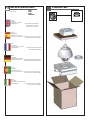
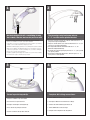
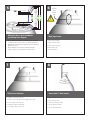
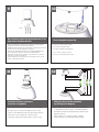
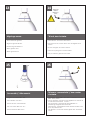
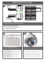
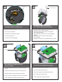
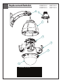
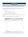
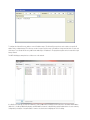
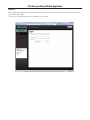
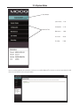
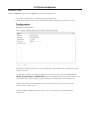
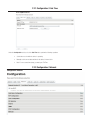
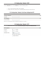
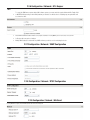
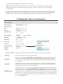
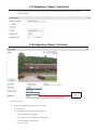
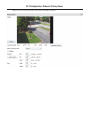
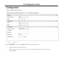
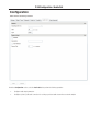
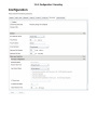
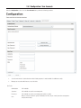
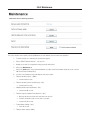
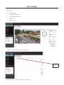
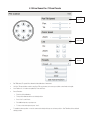
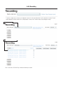
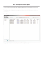
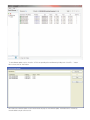
Installation and Operation Instructions
Before attempting to connect or operate this product, please
read these instructions completely.
EXO
Vandal
Resistant
HD
Camera
High Definition Camera Systems for Harsh Environments
EXVP7C2-2...............Rugged 1080P HD PTZ camera system, 20x optic zoom, H.264, ONVIF, extended temperature range, surge protection with
Pendent adaptor
EXVW7C2-2...............Rugged 1080P HD PTZ camera system, 20x optic zoom, H.264, ONVIF, extended temperature range, surge protection with
Wall mount
EXVP7C2-3................Rugged 1080P HD PTZ camera system, 30x optic zoom, H.264, ONVIF, extended temperature range, surge protection with
Pendent adaptor
EXVW7C2-3..............Rugged 1080P HD PTZ camera system, 20x optic zoom, H.264, ONVIF, extended temperature range, surge protection with Wall mount
Moog Inc.
Sensor and Surveillance Systems
© 2013, Moog Inc. All Rights Reserved
3650 Woodhead Drive Northbrook, IL. USA 60062
+1.847.498.0700 Fax: +1.847.498.1258 www.moogS3.com
81-IN5505 110513
IMPORTANT SAFEGUARDS
1
Read these instructions.
2
Keep these instructions.
3
Heed all warnings
4
Follow all instructions.
5
Do not use this apparatus near water.
6
Clean only with damp cloth.
7
Do not block any of the ventilation openings. Install in accordance with the
CAUTION
RISK OF ELECTRIC SHOCK
DO NOT OPEN
manufacturers instructions.
8
9
SAFETY PRECAUTIONS
Cable Runs- All cable runs must be within permissible distance.
CAUTION: TO REDUCE THE RISK OF
ELECTRIC SHOCK, DO NOT REMOVE
COVER ( OR BACK). NO USER- SERVICEABLE PARTS INSIDE. REFER SEVICING
TO QUALIFIED SERVICE PERSONNEL.
Mounting - This unit must be properly and securely mounted to a supporting
structure capable of sustaining the weight of the unit.
Accordingly:
a. This installation should be made by a qualified service person and should conform
to all local codes.
b. Care should be exercised to select suitable hardware to install the unit, taking into
account both the composition of the mounting surface and the weight of the unit.
10 Do not install near any heat sources such as radiators, heat registers, stoves, or other
apparatus ( including amplifiers) that produce heat.
11 Do not defeat the safety purpose of the polarized or grounding-type plug. A
polarized plug has two blades with one wider than the other. A grounding type
plug has two blades and a third grounding prong. The wide blade or the third
prong are provided for your safety. When the provided plug does not fit into your
outlet, consult an electrician for replacement of the obsolete outlet.
12 Protect the power cord from being walked on or pinched particularly at plugs,
convenience receptacles, and the point where they exit from the apparatus.
13 Only use attachment/ accessories specified by the manufacturer.
14 Use only with a cart, stand, tripod, bracket, or table specified by the manufacturer,
or sold with the apparatus. When a cart is used, use caution when moving the cart/
apparatus combination to avoid injury from tip-over.
15 Unplug this apparatus during lighting storms or when unused for long periods of time.
16 Refer all servicing to qualified service personnel. Servicing is required when the
apparatus has been damaged in any way, such as power-supply cord or plug is
damaged, liquid has been spilled of objects have fallen into the apparatus, the
The lightning flash with an arrowhead symbol,
within an equilateral triangle, is intended to
alert the user to the presence of non-insulated
“dangerous voltage” within the product’s
enclosure that may be of sufficient magnitude
to constitute a risk to persons.
Este símbolo se piensa para alertar al usuario a la presencia
del “voltaje peligroso no-aisIado” dentro del recinto de los
productos que puede ser un riesgo de choque eléctrico.
Ce symbole est prévu pour alerter I’utilisateur à la presence
“de la tension dangereuse” non-isolée dans la clôture de
produits qui peut être un risque de choc électrique.
Dieses Symbol soll den Benutzer zum Vorhandensein der
nicht-lsolier “Gefährdungsspannung” innerhalb der
Produkteinschließung alarmieren die eine Gefahr des
elektrischen Schlages sein kann.
Este símbolo é pretendido alertar o usuário à presença “di
tensão perigosa non-isolada” dentro do cerco dos produtos
que pode ser um risco de choque elétrico.
Questo simbolo è inteso per avvertire I’utente alla presenza
“di tensione pericolosa” non-isolata all’interno della
recinzione dei prodotti che può essere un rischio di scossa
elettrica.
apparatus has been exposed to rain or moisture, does not operate normally, or
has been dropped.
Be sure to periodically examine the unit and the supporting structure to make sure that the integrity
of the installation is intact. Failure to comply with the foregoing could result in the unit separating
from the support structure and falling, with resultant damages or injury to anyone or anything struck
by the falling unit.
UNPACKING
Unpack carefully. Electronic components can be
damaged if improperly handled or dropped. If an item
appears to have been damaged in shipment, replace
it properly in its carton and notify the shipper.
Be sure to save:
1 The shipping carton and packaging material.
They are the safest material in which to make future
shipments of the equipment.
2 These Installation and Operating Instructions.
SERVICE
If technical support or service is needed, contact us at
the following number:
TECHNICAL SUPPORT
AVAILABLE 24 HOURS
1 - 800 - 554 -1124
The exclamation point within an equilateral
triangle is intended to alert the user to
presence of important operating and
maintenance (servicing) instructions in the
literature accompanying the appliance.
Este símbolo del punto del exclamation se piensa para
alertar al usuario a la presencia de instrucciones importantes
en la literatura que acompaña la aplicación.
Ce symbole de point d’exclamation est prévu pour alerter
l’utilisateur à la presence des instructions importantes dans
la littérature accompagnant l’appareil.
Dieses Ausruf Punktsymbol soll den Benutzer zum
Vorhandensein de wichtigen Anweisungen in der Literatur
alarmieren, die das Gerät begleitet.
Este símbolo do ponto do exclamation é pretendido alertar o
usuário à presença de instruções importantes na literatura
que acompanha o dispositivo.
Questo simbolo del punto del exclamaton è inteso per
avvertire l’utente alla presenza delle istruzioni importanti nella
letteratura che accompagna l'apparecchio.
MADEIN
USA
BUY AMERICA COMPLIANT • COUNTRY OF ORIGIN U.S.A.
Product Warranty Registration
Register Your Products Online
www.moogS3.com/technical-support/product-registration
Moog values your patronage. We are solely committed to providing you with the highest quality products and
superior customer service. With 3-Year and 5-Year warranties (depending on the product purchased) we stand
behind every product we sell.
See full warranty details at www.moogS3.com/technical-support/warranty-plan/
:
• Simple and Trouble-Free RMA process
• Product / software updates
• Special promotions
• Eliminate the need to archive purchase documents such as receipts, purchase orders, etc.
Limited Warranty for Moog Products
Moog - Decatur Operations, subsequently referred to as “Manufacturer,” warrants these products to be free from defects in material or workmanship as follows:
PRODUCT CATEGORY
PARTS \ LABOR
All Enclosures and Electronics
Five (5) Years
Accessory Brackets
Five (5) Years
Controllers
Three (3) Years
Power Supplies / IR Illuminators
Three (3) Years
Poles / PolEvators / CamEvator
Three (3) Years
Warrior Series™ / Q-View™
Three (3) Years
SView Series
Three (3) Years 6 months if used in auto scan / tour operation
DeputyDome™, NiteTrac™, Igloo Dome, PurgeDome™
Three (3) Years 6 months if used in auto scan / tour operation
EXO Series Dome and Fixed Camera Systems*
Three (3) Years 6 months if used in auto scan / tour operation
EXO Series GeminEye Visible and Thermal Camera Systems
One (1) Year
™
™
™
™
During the labor warranty period, to repair the Product, Purchaser will either return the defective product, freight prepaid, or deliver it to Manufacturer at Moog Decatur
Operations, 2525 Park Central Boulevard, Decatur, Georgia, 30035. The Product to be repaired is to be returned in either its original carton or a similar package affording
an equal degree of protection with a RMA # (Return Materials Authorization number) displayed on the outer box or packing slip. To obtain a RMA# you must contact our
Technical Support Team at 800.554.1124, extension 101. Manufacturer will return the repaired product freight prepaid to Purchaser. Manufacturer is not obligated to
provide Purchaser with a substitute unit during the warranty period or at any time. After the applicable warranty period, Purchaser must pay all labor and/or parts charges.
The limited warranty stated in these product instructions is subject to all of the following terms and conditions.
TERMS AND CONDITIONS
1. NOTIFICATION OF CLAIMS: WARRANTY SERVICE: If Purchaser believes that the Product is defective in material or workmanship, then written notice with an explanation
of the claim shall be given promptly by Purchaser to Manufacturer. All claims for warranty service must be made within the warranty period. If after investigation,
Manufacturer determines the reported problem was not covered by the warranty, Purchaser shall pay Manufacturer for the cost of investigating the problem at its then
prevailing per incident billable rate. No repair or replacement of any Product or part thereof shall extend the warranty period of the entire Product. The specific warranty on
the repaired part only shall be in effect for a period of ninety (90) days following the repair or replacement of that part or the remaining period of the Product parts warranty,
whichever is greater.
2. EXCLUSIVE REMEDY: ACCEPTANCE: Purchaser’s exclusive remedy and Manufacturer’s sole obligation is to supply (or pay for) all labor necessary to repair any Product
found to be defective within the warranty period and to supply, at no extra charge, new or rebuilt replacements for defective parts.
3. EXCEPTIONS TO LIMITED WARRANTY: Manufacturer shall have no liability or obligation to Purchaser with respect to any Product requiring service during the warranty
period which is subjected to any of the following: abuse, improper use, negligence, accident, or acts of God (i.e., hurricanes, earthquakes), modification, failure of the
end-user to follow the directions outlined in the product instructions, failure of the end-user to follow the maintenance procedures recommended by the International Security
Industry Organization, written in product instructions, or recommended in the service manual for the Product. Furthermore, Manufacturer shall have no liability where a
schedule is specified for regular replacement or maintenance or cleaning of certain parts (based on usage) and the end-user has failed to follow such schedule; attempted
repair by non-qualified personnel; operation of the Product outside of the published environmental and electrical parameters, or if such Product’s original identification
(trademark, serial number) markings have been defaced, altered, or removed. Manufacturer excludes from warranty coverage Products sold AS IS and/or WITH ALL FAULTS
and excludes used Products which have not been sold by Manufacturer to the Purchaser. All software and accompanying documentation furnished with, or as part of the
Product is furnished “AS IS” (i.e., without any warranty of any kind), except where expressly provided otherwise in any documentation or license agreement furnished with
the Product. ANY COST ASSOCIATED WITH REMOVAL OF DEFECTIVE PRODUCT AND INSTALLATION OF REPLACEMENT PRODUCT IS NOT INCLUDED IN THIS WARRANTY.
4. PROOF OF PURCHASE: The Purchaser’s dated bill of sale must be retained as evidence of the date of purchase and to establish warranty eligibility.
DISCLAIMER OF WARRANTY
EXCEPT FOR THE FOREGOING WARRANTIES, MANUFACTURER HEREBY DISCLAIMS AND EXCLUDES ALL OTHER WARRANTIES, EXPRESS OR IMPLIED, INCLUDING, BUT
NOT LIMITED TO ANY AND/OR ALL IMPLIED WARRANTIES OF MERCHANTABILITY, FITNESS FOR A PARTICULAR PURPOSE AND/OR ANY WARRANTY WITH REGARD TO ANY
CLAIM OF INFRINGEMENT THAT MAY BE PROVIDED IN SECTION 2-312(3) OF THE UNIFORM COMMERCIAL CODE AND/OR IN ANY OTHER COMPARABLE STATE STATUTE.
MANUFACTURER HEREBY DISCLAIMS ANY REPRESENTATIONS OR WARRANTY THAT THE PRODUCT IS COMPATIBLE WITH ANY COMBINATION OF NON-MANUFACTURER
PRODUCTS OR NON-MANUFACTURER RECOMMENDED PRODUCTS PURCHASER MAY CHOOSE TO CONNECT TO THE PRODUCT.
LIMITATION OF LIABILITY
THE LIABILITY OF Manufacturer, IF ANY, AND PURCHASER’S SOLE AND EXCLUSIVE REMEDY FOR DAMAGES FOR ANY CLAIM OF ANY KIND WHATSOEVER, REGARDLESS
OF THE LEGAL THEORY AND WHETHER ARISING IN TORT OR CONTRACT, SHALL NOT BE GREATER THAN THE ACTUAL PURCHASE PRICE OF THE PRODUCT WITH RESPECT
TO WHICH SUCH CLAIM IS MADE. IN NO EVENT SHALL MANUFACTURER BE LIABLE TO PURCHASER FOR ANY SPECIAL, INDIRECT, INCIDENTAL, OR CONSEQUENTIAL
DAMAGES OF ANY KIND INCLUDING, BUT NOT LIMITED TO, COMPENSATION, REPLACEMENT LABOR COSTS, REIMBURSEMENT, OR DAMAGES ON ACCOUNT OF THE LOSS
OF PRESENT OR PROSPECTIVE PROFITS OR FOR ANY OTHER REASON WHATSOEVER.
* NOTE
Moog will repair or replace, at its option, any equipment which is damaged by transient voltage surge/spike or lightning strike (an “Occurrence”), while properly connected
to wired AC power line with protective ground. Any repair or modification of the equipment done by someone other than Moog voids the warranty.
Form 500-911 081913
!
Electrical Specifications
Power 24VAC
Class 2 Only
24 VAC
3.2 Amps
Total Power: 75 Watts
Tools Required:
English
EXPF7
EXSS7
EXSP7
EXRHW(P)7
.100” Flat Head Screwdriver
Phillips Head Screwdriver
7/16” Wrench or Socket
24 VAC
3.2 amperios
Energía Total: 75 vatios
Las Herramientas Requirieron: Destornillador Principal Plano Del 100"
Destornillador Principal Phillips
Español
24 VCA
3.2 ampères
Puissance Totale : 75 watts
Les Outils besoin :
Français
Deutsch
Tournevis Principal Plat De 100"
Tournevis Principal Phillips
24 VAC
3.2 Ampere
Gesamtenergie: 75 Watt
Werkzeuge Erforderten: 100"Flacher Hauptschraubenzieher
Kreuzkopfhauptschraubenzieher
24 VAC
3.2 ampères
Poder Total: 75 watts
As Ferramentas Requereram: Chave de fenda Principal Lisa Do 100"
Portuguese
Italiano
Chave de fenda Principal Phillips
24 VAC
3.2 ampère
Alimentazione Totale: 75 watt
Attrezzi Richiesti:
Cacciavite Capo Piano Del 100"
Cacciavite Capo "phillips"
Contents of Box
1
2
➞
4”-5”
Bracket is designed for 45° conduit fitting (If using
the conduit). Run wire into bracket, secure to wall.
• El soporte se diseña para la guarnición del conducto 45° (si usa el conducto).
Funcione con el alambre en el soporte seguro para emparedar.
• La parenthèse est conçue pour l'ajustage de précision du conduit 45° (si à l'aide du
conduit). Courez le fil dans la parenthèse bloquée pour murer.
• Haltewinkel ist für Befestigung des Rohres 45° bestimmt (wenn das Rohr verwendet
wird). Lassen Sie Draht in den Haltewinkel laufen, der, um zu ummauern sicher ist.
• O suporte é projetado para o encaixe da canalização 45° (se usando a canalização).
Funcione o fio no suporte seguro para murar.
• La staffa è progettata per il montaggio del condotto 45° (se per mezzo del condotto).
Faccia funzionare il legare nella staffa sicura per murare.
3
Secure lanyard to lanyard clip.
Trim incoming control and power wires to
4”- 5”, for either wall or pendent bracket.
• Recorte de control de entrada y los cables de alimentación de 4 "- 5",
para pared o soporte independiente.
• Coupez le contrôle d'entrée et les câbles d'alimentation à 4 "- 5", soit
pour mur ou un support indépendant.
• Trim eingehenden Kontrolle und Macht Drähte bis 4 "- 5", für
Wand-oder hängende Halterung.
• & entrante do controle da guarnição; pnha fios a 4” - 5”, para a parede
ou o suporte pendent.
• & ricevuto di controllo della disposizione; alimenti i legare a 4„ - 5„,
per la parete o la staffa pendent.
4
Complete ALL wiring connections.
• Asegure el acollador al clip del acollador.
• Termine TODAS LAS conexiones del cableado.
• Fixez la lanière à l'agrafe de lanière.
• Accomplissez TOUS LES raccordements de câblage.
• Befestigen Sie Abzuglinie an Abzuglinieclip.
• Schließen Sie ALLE Verdrahtungsanschlüsse ab.
• Fixe o colhedor ao grampo do colhedor.
• Termine TODAS AS conexões da fiação.
• Assicuri la cordicella alla clip della cordicella.
• Completi TUTTI I collegamenti dei collegamenti.
5
6
!
Wiring the dome can be completed
by referring to the diagram.
Important
Gasket
Must be
in place
Align large arrows.
• Atar con alambre la bóveda puede ser terminada refiriendo al diagrama.
• Alinee las flechas grandes.
• Le câblage du dôme peut être accompli en se rapportant au diagramme.
• Alignez les grandes flèches.
• Das Verdrahten der Haube kann durchgeführt werden, indem man auf das
Diagramm sich bezieht.
• Richten Sie große Pfeile aus.
• Wiring a abóbada pode ser terminado consultando ao diagrama.
• Alinhe grandes setas.
• Legare la cupola può essere completato riferendosi allo schema.
• Allini le grandi frecce.
7
To lock, turn clockwise.
8
Secure with ¼” Allen wrench.
• Para trabarse, dar vuelta a la derecha.
• Asegure con la llave Allen del ¼”.
• Pour fermer à clef, tourner dans le sens des aiguilles d'une montre.
• Fixez clé Allen avec de ¼ ».
• Zu sich verriegeln, nach rechts drehen.
• Sichern Sie mit ¼“ Inbusschlüssel.
• Para travar, para girar no sentido horário.
• Fixe com chave Allen do ¼ de”.
• Per per chiudere, girare in senso orario.
• Fissi con chiave di Allen del ¼„.
9
10
4”-5”
Trim incoming control and power wires to 4-5” for
either wall or pendent bracket.
• Ajuste los alambres entrantes del control y de la energía a
4-5” para la pared o el soporte pendiente.
• Équilibrez les fils entrants de commande et de puissance à 4-5
» pour le mur ou la parenthèse en suspens.
• Trimmen Sie ankommende Steuer- und Energiendrähte bis
4-5“ entweder für Wand oder pendent Haltewinkel.
• Apare fios entrantes do controle e do poder a 4-5” para a
parede ou o suporte pendent.
• Assetti i legare ricevuti di potere e di controllo a 4-5„ per la
parete o la staffa pendent.
11
Complete all wiring connections
(coax wire not supplied).
Secure lanyard to lanyard clip.
• Asegure el acollador al clip del acollador.
• Fixez la lanière à l'agrafe de lanière.
• Befestigen Sie Abzuglinie an Abzuglinieclip.
• Fixe o colhedor ao grampo do colhedor.
• Assicuri la cordicella alla clip della cordicella.
12
Wiring the dome can be completed
by referring to the diagram.
• Termine todas las conexiones del cableado (alambre coaxil no suministrado).
• Atar con alambre la bóveda puede ser terminada refiriendo al diagrama.
• Accomplissez tous les raccordements de câblage (fil coaxial non fourni).
• Le câblage du dôme peut être accompli en se rapportant au diagramme.
• Schließen Sie alle Verdrahtungsanschlüsse ab (koaxialer Draht nicht geliefert).
• Das Verdrahten der Haube kann durchgeführt werden, indem man auf das
Diagramm sich bezieht.
• Termine todas as conexões da fiação (fio co-axial não fornecido).
• Completi tutti i collegamenti dei collegamenti (legare coassiale non fornito).
• Wiring a abóbada pode ser terminado consultando ao diagrama.
• Legare la cupola può essere completato riferendosi allo schema.
13
14
10
Important
Gasket
Must be in
place
!
Align large arrows.
To lock, turn clockwise.
• Alinee las flechas grandes.
• Para trabarse, dar vuelta a la derecha.
• Alignez les grandes flèches.
• Pour fermer à clef, tourner dans le sens des aiguilles d'une
montre.
• Richten Sie große Pfeile aus.
• Alinhe grandes setas.
• Allini le grandi frecce.
15
Secure with ¼” Allen wrench.
• Asegure con la llave Allen del ¼”.
• Fixez clé Allen avec de ¼”.
• Sichern Sie mit ¼“ Inbusschlüssel.
• Fixe com chave Allen do ¼ de”.
• Fissi con chiave di Allen del ¼”.
• Zu sich verriegeln, nach rechts drehen.
• Para travar, para girar no sentido horário.
• Per per chiudere, girare in senso orario.
16
!
To loosen - unscrew bolts ½” turn counter
clockwise.
• Para aflojar - desatornille a la derecha contrario de la vuelta
del ½ de los pernos”.
• Pour se desserrer - dans le sens des aiguilles d'une montre de
tour dévissez de boulons ½ » contre-.
• Um sich zu lösen - schrauben Sie Schraubbolzen ½“
Umdrehungs-Gegenrechtses herum ab.
• Para afrouxar - desaparafuse sentido horário contrário volta
do ½ dos parafusos da”.
• Per allentare - sviti in senso orario di girata del ½ dei bulloni„
contro.
Wiring Connections for ALL Housings
17
A
A
24VDC
B
B
C
RJ45
D
POWER
1
2
3
24Vac
24Vac
GND
1
2
3
Speaker +
1
2
Alarm (In)
Blue
Alarm (Out)
Black/White
3
4
Alarm (In/GND)
Alarm (Out)
Red/White
Red
Orange
Green/White
75 Watts
AUDIO
C
D
Audio GND
MIC +
Gray
Brown
White
ALARM
Violet
Make the appropriate male and female connections.
•
•
•
•
•
Haga las conexiones masculinas y femeninas apropiadas.
Établissez les rapports masculins et femelles appropriés.
Stellen Sie die passenden männlichen und weiblichen Beziehungen her.
Faça as conexões masculinas e fêmeas apropriadas.
Faccia i collegamenti maschii e femminili adatti.
12
19
12
18
,5
22
,75
20
1,0
18
1,5
16
2,5
14
4
12
6
10
2
MM
AWG
Pan / Tilt Unit
These
are recommended
maximum
The
beam
angle may be
adjusted on the
distancesoffor
24VAC
bottom
the
unit.with a 10% voltage drop.
• Éstos se recomiendan las distancias máximas para 24VAC con
una gota del voltage del 10%.
• Ceux-ci sont recommandés des distances maximum pour 24VAC
avec une chute de tension de 10%.
• Diese werden maximale Abstände für 24VAC mit einem 10%
Spannungsabfall empfohlen.
• Estes são recomendados distâncias máximas para 24VAC com
uma queda de tensão de 10%.
• Questi sono suggeriti distanze massime per 24VAC con una
differenza de potenziale di 10%.
The beam angle may be adjusted on the
Tobottom
add SDof
card,
the you
unit.must remove Pan / Tilt unit.
• Para añadir una tarjeta SD, debe quitar Pan / unidad Tilt.
• Pour ajouter carte SD, vous devez supprimer Pan / Tilt unité.
• Auf SD-Karte hinzufügen, müssen Sie entfernen Pan / Tilt-Einheit.
• Para adicionar cartão SD, você deve remover o Pan / Tilt unidade.
• Per aggiungere scheda SD, è necessario rimuovere Pan / Tilt unità.
20
Captive Screw
To remove, loosen captive screw.
• Para quitarlo, tornillo cautivo suelto.
21
Power Network Cables
Disconnect cables, and remove
Pan / Tilt from base bracket in housing.
• Per rimuovere, sciolto vite imperdibile.
• Desconecte los cables y retire la cacerola / de la inclinación
del soporte de base en materia de vivienda.
• Débranchez les câbles, puis retirez Pan / Tilt de support de
base en matière de logement.
• Ziehen Sie die Kabel, und entfernen Pan / Tilt aus Grundträger
im Gehäuse.
• Desconecte os cabos e remover Pan / Tilt do suporte de
base em habitação.
• Scollegare i cavi e rimuovere Pan / Tilt dalla staffa base in custodia.
22
23
• Pour l'enlever, vis captive lâche.
• Zum Entfernen loser unverlierbare Schraube.
• Para remover, parafuso solto.
SD Card Slot
SD card slot is located at the base
of Pan / Tilt unit.
• Ranura para tarjetas SD se encuentra en la base? De la unidad
Pan / Tilt.
• Fente pour carte SD se trouve à la base? De l'unité de Pan / Tilt.
• SD-Kartensteckplatz an der Basis liegt der Pan / Tilt-Einheit.
• Slot para cartão SD está localizado na base? De Pan / Tilt unidade.
• Slot per scheda SD si trova alla base? Del Pan / Tilt unità.
SD Card
(Not Supplied)
Insert SD card if application requires.
• Inserte la tarjeta SD si la aplicación requiere.
• Insérez la carte SD si l'application l'exige.
• Legen Sie eine SD-Karte, wenn die Anwendung erfordert.
• Insira o cartão SD se a aplicação requer.
• Inserire la scheda SD se l'applicazione richiede.
24
25
Tab
Connect Lanyard to trim ring assembly.
Align key slot to housing pins, close and turn
counterclockwise, secure screws to lock.
• Conecte el acollador con el montaje del anillo del ajuste.
• Alinear ranura de la llave a los pines de vivienda, cierre y gire en sentido contrario,
asegurar los tornillos de bloqueo.
• Reliez la lanière à l'anneau d'équilibre.
• Schließen Sie Abzuglinie an Ordnung Ring an.
• Conecte o colhedor ao conjunto do anel da guarnição.
• Colleghi la cordicella al complessivo dell'anello della cornice.
• Alignez la fente clé de broches de logement, fermer et tourner vers la gauche,
vis sécurisées pour le verrouiller.
• Richten Keilschlitz zu Gehäusestifte, schließen und gegen den Uhrzeigersinn
drehen, sichere Schrauben zu verriegeln.
• Alinhe a ranhura chave pinos de habitação, feche e vire anti-horário, parafusos
de segurança para bloquear.
• Allineare fessura chiave per perni presenti, chiudere e girare in senso antiorario,
viti sicure per bloccare.
Replacement Parts List
EXVW7C2-2
EXVW7C2-3
6
EXVP7C2-2
EXVP7C2-3
7
1
2
3
4
5
1
2
2
3
4
5
5
6
7
PART NUMBER
111-HGR73641G
65-EXPT-2000
65-EXPT-3000
30-VL4281
25-DCR7-9000
20-DC4357
20-DT4357
110-50VL3551G
110-50VL3606G
DESCRIPTION
Metal Housing Top Assembly
20x Pan Tilt Assembly
30x Pan Tilt Assembly
Liner Assembly (2 parts)
Trim Ring Assembly - PC Dome _Clear
PC Dome Clear
PC Dome Tinted
Wall Mount Bracket
Pendent Mount Bracket
TABLE OF CONTENTS
Software Sections
Moog Discovery Tool ...................................................... .....................................................................................................
1.0.0
Using the Moog EXO Web Application .............................
.....................................................................................................
2.0.0
System Status ............................................................... .....................................................................................................
2.1.0
System Configuration ..................................................... .....................................................................................................
2.2.0
Configuration / Date Time ............................................... .....................................................................................................
2.2.1
Configuration / Network .................................................. .....................................................................................................
2.2.2
Configuration / Network / DHCP ...................................... .....................................................................................................
2.2.3
Configuration / Network / Host Name Configuration-NPT .. .....................................................................................................
2.2.4
Configuration / Network / HTTP ....................................... .....................................................................................................
2.2.5
Configuration / Network / API - Bonjour ........................... .....................................................................................................
2.2.6
Configuration / Network / SNMP Configuration ................. .....................................................................................................
2.2.7
Configuration / Network / RTSP Configuration .................. .....................................................................................................
2.2.8
Configuration / Network / Multicast ................................. .....................................................................................................
2.2.9
Configuration / Video In .................................................. .....................................................................................................
2.3.0
Configuration / Video In / Video Input ............................... .....................................................................................................
2.3.1
Configuration / Video In / Sensor ..................................... .....................................................................................................
2.3.2
Configuration / Video In / Video Compression ................... .....................................................................................................
2.3.3
Configuration / Video In / Point to Point ............................ .....................................................................................................
2.3.4
Configuration / Video In / Text Overlay .............................. .....................................................................................................
2.3.5
Configuration / Video In / Motion Detection ...................... .....................................................................................................
2.3.6
Configuration / Video In / Privacy Zones ........................... .....................................................................................................
2.3.7
Configuration / Audio In .................................................. .....................................................................................................
2.3.8
Configuration / Audio Out ............................................... .....................................................................................................
2.3.9
Configuration / Recording ............................................... .....................................................................................................
2.4.0
Configuration / User Accounts ......................................... .....................................................................................................
2.4.1
Maintenance ................................................................. .....................................................................................................
3.0.0
Live Viewer .................................................................... .....................................................................................................
4.0.0
Live Viewer Pan / Tilt and Presets ................................... .....................................................................................................
4.1.0
Recording .....................................................................
.....................................................................................................
5.0.0
Performing Batch Firmware Update ................................
.....................................................................................................
6.0.0
Point to Point Connections .............................................. .....................................................................................................
7.0.0
Troubleshooting Guide .................................................... .....................................................................................................
8.0.0
SOFTWARE SETUP
1.0.0 Moog Discovery Tool
By factory default, the Moog EXO Camera is configured in DHCP. If you are not using a DHCP server it will automatically allocate itself
an APIPA (Automatic Private IP Addressing) address in the range 169.254.0.1 to 169.254.255.254 with subnet mask 255.255.0.0.
Initial device network configuration is done via the Moog Discovery Tool (MDT), a tool provided by Moog that can be found on the
company’s web site and on the flash drive supplied with each camera system. The flash drive also contains a copy of Microsoft
Silverlight 5. Both programs should be installed on the your local server.
The MDT plays 3 important roles:
1.
Discovery of all Moog EXO Cameras
2.
Allows for remote configuration of the IP address and subnet mask
3.
Permits batch firmware upgrade of all common EXO devices
Note: Silverlight is a free plug in and is required to interface with the Moog EXO Web brower.
Once your device is installed on your network and powered up, launch MDT from any computer on the network and the following window
will be displayed:
The MDT supports 2 ways to discover a device. The first way doesn’t need any configuration and uses the Bonjour discovery protocol.
In order to be able to discover a device via Bonjour, the network must support multicast delivery.
If it is not the case, you can use the second way, which is the Unicast Discovery. The Unicast Discovery can be configured by using the
“Unicast Discovery” configuration form. This configuration form is available via the Admin / Unicast Discovery menu option.
To configure the Unicast Discovery, add one or more IP address ranges. The Unicast Discovery tries to reach a device at a specific IP
address in the configured ranges. The discovery can be a long process if the range of IP addresses is large and the device is at the end
of the range. To accelerate the discovery, add several small ranges of IP addresses. The ping timeout option can be increased for a high
latency network.
The MDT will display as many devices as it discovers on the network
If no DHCP server was able to assign an IP address to a Moog EXO Camera, it will appear in the MDT device list with an APIPA address
(169.254.*.*). If a Moog EXO Camera displays an APIPA address it must be configured with a valid IP address before it can be remotely
configured by selecting the ‘’Assign IP address’’ from the selection list and configuring the TCP / IP settings.
To assign IP Address, update firmware, or configure Moog web interface, right click on highlighted serial number / Mac Address.
Assign IP Address(es)
Once the IP information is set, the Silverlight web application served by the EXO Camera can be launched from the MDT or directly in your
web browser by typing the device’s IP address in the address bar. You can start to use your networked video management system for final
system configuration or you can configure advanced parameters using the Moog EXO web based management.
2.0.0 Using the Moog EXO Web Application
Application
When entering the Web Application, the following window will be displayed. You will be asked a username and password. The default User
name and Password is ‘admin’.
(To reset the user name and password see / Configurations / User Accounts)
2.1.0 System Status
Status Window
System Status - 2.1.0
Configuration - 2.2.0
Main Menu Tabs
Maintenance - 3.0.0
Live Viewer
- 4.0.0
Recording
- 5.0.0
Upon successfully logging into the web interface, a welcome screen will be displayed. The welcome screen shows general device health
status as well as firmware version and system uptime.
2.2.0 System Configuration
Configuration / System
Under the Configuration section, select the System tab to perform the following operations:
•
View product model information, current firmware version and serial number.
•
Specify a custom name; this name can be used by third-party software to display a selected name for the device.
-
Enable edge recording by checking the box “Use Recorder Module” checkbox. Disabling edge recording will accelerate
the device’s boot time.
-
To enable edge recording an SD card must be added to the camera interface card, located on the EXO pan/tilt device.
SD cards are not provided as a standard feature. Directions for installing the SD card are provided in the first section
of this installer manual. Edge recording set up is done through the Recording Tab in the Live Viewer EXO screen.
-
Note: Recording menu will only be displayed when user recorder module check box is selected. You must save,
and then reboot to complete selection.
-
SD Card: Use 2GB to 32 GB Micro SD Card of class 6 or above. You must make sure the card is formatted to
FAT32 or EXT3.
2.2.1 Configuration / Date Time
Under the Configuration section, select the Date Time tab to perform the following operations:
•
Set the time zone in which the device is operating.
•
Manually set the current date and time for the device’s internal clock.
•
Note: For an accurate time stamp, you must sync UTC Time.
2.2.2 Configuration / Network
Configuration / Network
2.2.3 Configuration / Network / DHCP
Under the Configuration section, select the Network tab to perform the following operations:
•
Set the encoder’s IP parameters; DHCP or static IP information.
•
Configure an NTP server to allow the device to automatically update its internal clock using an NTP server.
2.2.4 Configuration / Network / Host Name Configuration-NPT
NPT Server- use when desiring to have local network time as default, to do so you must…….
2.2.5 Configuration / Network / HTTP
•
Change the device’s HTTP configuration, Note: Avoid changing these settings unless absolutely necessary.
2.2.6 Configuration / Network / API- Boujour
NOTE:
•
To control the EXO Camera system with a VMS software system, you must enable the required Network APIs. Enable PSIA
or GENETEC API depending on which VMS platform you intend to use with the device. Disabling any unrequired APIs will
accelerate boot time.
•
Note: ONVIF standard is built in and does not require activation. If using ONVIF you do not need to select an API.
•
Set Bonjour discovery protocol settings.
•
Modify SNMP settings to match with any SNMP software you wish to use for monitoring the device.
2.2.7 Configuration / Network / SNMP Configuration
2.2.8 Configuration / Network / RTSP Configuration
2.2.9 Configuration / Network / Multicast
If using Mulitcast output, Insert Multicast start IP, and select start port.
2.3.0 Configuration / Video In
2.3.1 Configuration / Video In / Video Input
Under the Configuration section, select the Video In tab to perform the following operations:
Digital format – choices are, 720 30fps, 720 60fps, 1080 30fps, 1080 25fps. Note max camera output with WDR Active is 15fps (1080p).
2.3.2 Configuration / Video In / Sensor
Configure camera bloc / sensor parameters. These parameters will also be saved to the camera bloc itself if possible:
Use the narrow pull down function for vertical and horizontal rotation of the image.
(Note: Activating WDR at 1080P will reduce maximum frame rate to 15fps.)
Configure video compression parameters for any of the three available codec instances (Primary H.264, Secondary H.264 and
MJPEG). Most VMS software solutions will interact with these parameters and thus it is suggested to leave these at default values
in the web interface.
VBR aggressiveness however is unique to Moog EXO Cameras and proposes various levels (disabled to aggressive) of motion triggered
rate control. The more aggressive the setting, the more variation motion will have on the rate control. It is strongly suggested to disable
VBR aggressiveness for low bit rate scenarios (below 1Mbps) as this parameter may negatively affect perceived video quality.
2.3.3 Configuration / Video In / Video Compression
Frame per sec (fps):
➞
Set Quantization (QP) level to desired rate. The higher the number the greater the compression. (16 very low, 51 very high)
Frame Rate
-
Allows you to specify the frame rate to be used by the codec.
Rate Control
-
Allows you to choose between Variable Bit Rate and Constant Bit Rate. The first option will instruct the H.264
codec to dynamically adjust the bit rate in order to meet both the target quality (QP) and frame rate settings.
The second option will instruct the H.264 codec to prioritize target bit rate and vary quality (QP) first and frame
rate as a last resort.
Min/Max QP
-
This parameter allows you to specify the compression range that the codec will use to determine image quality
during compression. In order to force a specific quality setting, you can set the minimum and maximum to the
same value. The lower the value, the better the quality will be.
-
This parameter allows you to specify if the codec should take into account the level of motion in the image for bit
rate calculations. You can select from Conservative, Moderate and Aggressive options for this setting. Using the
Conservative option, the codec will allow bit rate to drop up to ¾ of the configured target bit rate when no motion
is detected in the image. Using the Moderate option, the codec will allow bit rate to drop up to ½ of the configured
target bit rate when no motion is detected in the image. Using the Aggresive option, the codec will allow bit rate to
drop up to ¼ of the configured target bit rate when no motion is detected in the image. You can disable this feature
by selecting the disabled option.
VBR Aggressiveness
2.3.4 Configuration / Video In / Point to Point
•
Configure point to point video connections (up to three) for creating persistent video streams from the encoder to
a network endpoint.
2.3.5 Configuration / Video In / Text Overlay
Text Box
To insert a text overlay:
•
There are (2) available strings (Text blocks). Select string.
•
Select string size.
•
For string position click mouse inside string position box.
o
Text bar will appear on video image.
o
If you wish to relocate, simply click in desired position.
o
Type desired text into String Text Box.
o
Press Save Button.
2.3.6 Configuration / Video In / Motion Detection
Select from 1 of 4 available regions:
•
With mouse click on region position box.
•
Bring mouse pointer to view window and drag box around area for motion detection.
•
Select desired Frame Count, Sensitivity and Thresholds.
•
Press “Save” button to store information.
•
You can select up to (4) separate “Motion” windows.
-
Frame count: Number of frames required to trigger motion
-
Sensitivity: No sensitivity, 100 MAX sensitivity
-
Threshold: % of image required to trigger, both threshold must have a value; “off” value must be lower than “on”.
2.3.7 Configuration / Video In / Privacy Zones
Privacy Zones are used to block out video in areas view is not permitted or desired.
To add a Privacy Zone:
•
Select the Zone to be identified with privacy area. There are up to 16 zones available.
•
With the mouse, click on Privacy Zone Position Box.
•
Move mouse pointer over the Image Window, click and draw a box on the area you wish to see video.
•
Press the “Save” button to store.
2.3.8 Configuration / Audio In
Under the Configuration section, select the Audio In tab to perform the following operations:
•
Configure audio input compression parameters.
•
Configure point to point audio connections (up to three) for creating persistent audio streams from the encoder to
a network endpoint.
2.3.9 Configuration / Audio Out
Under the Configuration section, select the Audio Out tab to perform the following operations:
•
Configure audio output parameters.
•
Configure a point to point audio connection for receiving a persistent audio stream from a network endpoint.
2.4.0 Configuration / Recording
Note: Recording Menu will NOT be visible unless activated; see 2.20 System configuration.
•
Grooming mode; Select method to remove files from full SD card chronological will remove old files first.
2.4.1 Configuration / User Accounts
Under the Configuration section, select the User Accounts tab to perform the following operations:
•
Select the web interface’s authentication method. A dual passphrase is made available for additional security.
•
Manage user accounts which have access to the device.
User Roles:
Administrator:
All is available
Superuser:
All is available except the user management
Poweruser:
All is available except the user management and the recording
User:
Only access basic operations: system information, live video (no ptz controls), date time management
and password change
3.0.0 Maintenance
This section describes how to update your Moog EXO Cameras to newer firmware versions from the web application.
1.
To find the latest file go to www.moogS3.com/technical-support/.
2.
Click on “EXO PTZ Camera Firmware” - click, save file.
3.
Navigate to your device’s web application using your favorite web browser.
4.
Click on the Maintenance tab.
5.
Click on the Update button, locate downloaded firmware. You will be asked for the firmware update file; please select the
.iof file which was provided by Moog.
6.
You will see the following messages indicating the status of the update:
o
Firmware upload in progress... (100%)
•
o
Firmware uploaded. Saving to internal storage... (0%)
•
o
o
Lasts around 105 seconds.
Firmware ready for installation. Rebooting device... (0%)
•
Web page will disconnect from device until device has rebooted.
•
You will be prompted for login once the device is up again.
•
Lasts around 110 seconds.
Testing firmware stability... (26%)
•
o
Lasts around 45 seconds.
Validating and decompressing firmware... (0%)
•
o
Lasts around 95 seconds.
Lasts 120 seconds.
Firmware update complete. (100%)
4.0.0 Live Viewer
Use Live View for:
•
Live Camera View
•
Start and Stop Recording
•
Pan / Tilt and Camera Control
•
Setting Presets
•
Adjust View Scale
To enable live you must activate by pressing the “Play” button.
Play Button
To adjust viewing scale for 1024 x 768 monitor, press smaller view.
4.1.0 Live Viewer Pan / Tilt and Presets
Pan/Tilt
Controls
Lens Control
Preset
Controls
•
Pan Tilt Control; To operate Press Arrow in desired direction of movement.
•
Use Pan / Tilt speed slider controls to vary Pan / Tilt speed control, to increase speed, slide control knob to the right.
•
Lens Funtion use +/- buttons to update Iris, Zoom and Focus.
•
Preset Functions.
•
o
First Select Preset Number.
o
Then position Camera and lens to desired position.
o
Press “Set” to save Preset.
o
For additional presets, repeat process.
o
To clear, select desired preset press “clear”.
To establish a home position – move the camera to desired position, press set home position – Pan Tilt will use this as default
start up position.
5.0.0 Recording
To activate recording mode you must go to Configuration / System / Use Recorder Mode. Click “Use Recorder Mode” checkbox. This will
activate addional Recording controls in the recording window. You must “Save” and then “Reboot” after making this change.
> Select Video Input
> Select Date of the Recording
Then select the filed clip you wish to view
Note: You must have either VLC Player or Windows Media Player installed.
6.0.0 Performing Batch Firmware Update
This section describes how to perform a batch update of multiple Moog EXO Camera devices to newer firmware versions from the MDT.
The batch firmware update works by starting a firmware update session. Only one session at time is allowed and only 20 devices can be
selected by session.
From the MDT, select one or more devices of the same type.
By using the right mouse button on the selected devices, choose the “Firmware Update” menu option.
To start a firmware update session, choose the “.iof” file corresponding to the new firmware by clicking to the “Select File …” button.
Once selected, click the “Start” button.
Once started, the “Firmware Update Session” window shows the progress of the firmware update. This window can be closed at any
moment without losing the current session.
If closed, the progress of the current session can be followed by reopening the “Firmware Update Session” window by clicking the
from the “Tools” toolbar.
button
Once done, clear the current session from the “Firmware Update Session” window and restart a new session if needed.
7.0.0 Point to Point Connections
Point-to-point connections between a Moog EXO Camera and a Decoder can be configured using the device’s web application.
In the Moog EXO web application, in the Configuration section, go to the Video In tab. Scroll down all the way to the bottom of the
configuration page. The last 3 sections are named Point to Point 1, 2 and 3.
Here’s a quick overview of the settings available for a connection:
•
Enabled: Indicates whether this connection is to be used.
•
Description: Free-form user description of the connection, not used by the device.
•
Encoder: Indicates which video feed is to be sent over the point-to-point connection. Possible values include «Primary H.264
» and «Secondary H.264». These values refer to the encoders configured in previous sections of the same web page.
•
Destination IP: Address where to send the video. This is usually the address of a Decoder. The destination can also be a
multicast group address. DNS names are not yet supported, only IP addresses.
•
Destination Port: Network port where to send the video. This value must match the port value in the Decoder.
Once all the settings have been set, click on Save at the bottom of the page to apply them. The Moog EXO Camera then creates or updates
the connection as needed.
8.0.0 Troubleshooting Guide
•
•
Device does not seem to boot-up
o
Verify that a 24Vac power supply is connected to the device.
o
When a valid power source is detected, the status Pan / Tilt LED, power will light up GREEN.
Cannot discover the device or communicate via the network
o
Dynamic discovery of the Moog Camera requires multicast networking to be supported by your network and switch
equipment. (Bonjour protocol)
o
Make sure you have connected the device to your network.


![取扱説明書[NR-E430V/430VL/F430V] (3.76 MB/PDF)](http://vs1.manualzilla.com/store/data/006648042_2-89ac55d92c1fb0f3590623e547ebc7e0-150x150.png)