1
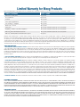
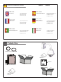
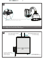
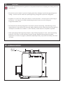
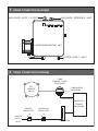
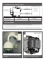
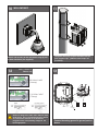
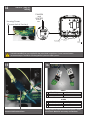
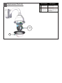
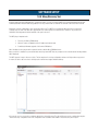
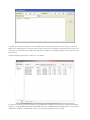
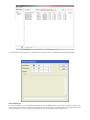
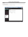
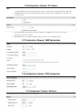
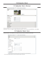
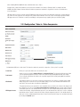
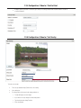
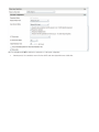
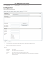
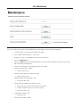
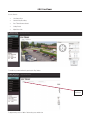
Installation and Operation Instructions Before attempting to connect or operate this product, please read these instructions completely. EXO Explosion Proof HD Camera High Definition Camera Systems for Harsh Environments EXPD7C1-2................Purged 1080P HD PTZ camera system, 20x optic zoom, H.264 support, ONVIF: Class I Division 2 Groups A, B, C and D EXPD7C1-3................Purged 1080P HD PTZ camera system, 20x optic zoom, H.264 support, ONVIF: Class I Division 2 Groups A, B, C and D EXPD7C2-2................Purged 1080P HD PTZ camera system, 20x optic zoom, H.264 support, ONVIF: Class II Division 2 Groups E, F and G EXPD7C2-3................Purged 1080P HD PTZ camera system, 20x optic zoom, H.264 support, ONVIF: Class II Division 2 Groups E, F and G Moog Inc. Sensor and Surveillance Systems © 2013, Moog Inc. All Rights Reserved 3650 Woodhead Drive Northbrook, IL. USA 60062 +1.847.498.0700 Fax: +1.847.498.1258 www.moogS3.com 81-IN5515 121113 IMPORTANT SAFEGUARDS 1 Read these instructions. 2 Keep these instructions. 3 Heed all warnings 4 Follow all instructions. 5 Do not use this apparatus near water. 6 Clean only with damp cloth. 7 Do not block any of the ventilation openings. Install in accordance with the CAUTION RISK OF ELECTRIC SHOCK DO NOT OPEN manufacturers instructions. 8 9 SAFETY PRECAUTIONS Cable Runs- All cable runs must be within permissible distance. CAUTION: TO REDUCE THE RISK OF ELECTRIC SHOCK, DO NOT REMOVE COVER ( OR BACK). NO USER- SERVICEABLE PARTS INSIDE. REFER SEVICING TO QUALIFIED SERVICE PERSONNEL. Mounting - This unit must be properly and securely mounted to a supporting structure capable of sustaining the weight of the unit. Accordingly: a. This installation should be made by a qualified service person and should conform to all local codes. b. Care should be exercised to select suitable hardware to install the unit, taking into account both the composition of the mounting surface and the weight of the unit. 10 Do not install near any heat sources such as radiators, heat registers, stoves, or other apparatus ( including amplifiers) that produce heat. 11 Do not defeat the safety purpose of the polarized or grounding-type plug. A polarized plug has two blades with one wider than the other. A grounding type plug has two blades and a third grounding prong. The wide blade or the third prong are provided for your safety. When the provided plug does not fit into your outlet, consult an electrician for replacement of the obsolete outlet. 12 Protect the power cord from being walked on or pinched particularly at plugs, convenience receptacles, and the point where they exit from the apparatus. 13 Only use attachment/ accessories specified by the manufacturer. 14 Use only with a cart, stand, tripod, bracket, or table specified by the manufacturer, or sold with the apparatus. When a cart is used, use caution when moving the cart/ apparatus combination to avoid injury from tip-over. 15 Unplug this apparatus during lighting storms or when unused for long periods of time. 16 Refer all servicing to qualified service personnel. Servicing is required when the apparatus has been damaged in any way, such as power-supply cord or plug is damaged, liquid has been spilled of objects have fallen into the apparatus, the The lightning flash with an arrowhead symbol, within an equilateral triangle, is intended to alert the user to the presence of non-insulated “dangerous voltage” within the product’s enclosure that may be of sufficient magnitude to constitute a risk to persons. Este símbolo se piensa para alertar al usuario a la presencia del “voltaje peligroso no-aisIado” dentro del recinto de los productos que puede ser un riesgo de choque eléctrico. Ce symbole est prévu pour alerter I’utilisateur à la presence “de la tension dangereuse” non-isolée dans la clôture de produits qui peut être un risque de choc électrique. Dieses Symbol soll den Benutzer zum Vorhandensein der nicht-lsolier “Gefährdungsspannung” innerhalb der Produkteinschließung alarmieren die eine Gefahr des elektrischen Schlages sein kann. Este símbolo é pretendido alertar o usuário à presença “di tensão perigosa non-isolada” dentro do cerco dos produtos que pode ser um risco de choque elétrico. Questo simbolo è inteso per avvertire I’utente alla presenza “di tensione pericolosa” non-isolata all’interno della recinzione dei prodotti che può essere un rischio di scossa elettrica. apparatus has been exposed to rain or moisture, does not operate normally, or has been dropped. Be sure to periodically examine the unit and the supporting structure to make sure that the integrity of the installation is intact. Failure to comply with the foregoing could result in the unit separating from the support structure and falling, with resultant damages or injury to anyone or anything struck by the falling unit. UNPACKING Unpack carefully. Electronic components can be damaged if improperly handled or dropped. If an item appears to have been damaged in shipment, replace it properly in its carton and notify the shipper. Be sure to save: 1 The shipping carton and packaging material. They are the safest material in which to make future shipments of the equipment. 2 These Installation and Operating Instructions. SERVICE If technical support or service is needed, contact us at the following number: TECHNICAL SUPPORT AVAILABLE 24 HOURS 1 - 800 - 554 -1124 The exclamation point within an equilateral triangle is intended to alert the user to presence of important operating and maintenance (servicing) instructions in the literature accompanying the appliance. Este símbolo del punto del exclamation se piensa para alertar al usuario a la presencia de instrucciones importantes en la literatura que acompaña la aplicación. Ce symbole de point d’exclamation est prévu pour alerter l’utilisateur à la presence des instructions importantes dans la littérature accompagnant l’appareil. Dieses Ausruf Punktsymbol soll den Benutzer zum Vorhandensein de wichtigen Anweisungen in der Literatur alarmieren, die das Gerät begleitet. Este símbolo do ponto do exclamation é pretendido alertar o usuário à presença de instruções importantes na literatura que acompanha o dispositivo. Questo simbolo del punto del exclamaton è inteso per avvertire l’utente alla presenza delle istruzioni importanti nella letteratura che accompagna l'apparecchio. MADEIN USA BUY AMERICA COMPLIANT • COUNTRY OF ORIGIN U.S.A. Product Warranty Registration Register Your Products Online www.moogS3.com/technical-support/product-registration Moog values your patronage. We are solely committed to providing you with the highest quality products and superior customer service. With 3-Year and 5-Year warranties (depending on the product purchased) we stand behind every product we sell. See full warranty details at www.moogS3.com/technical-support/warranty-plan/ : • Simple and Trouble-Free RMA process • Product / software updates • Special promotions • Eliminate the need to archive purchase documents such as receipts, purchase orders, etc. Limited Warranty for Moog Products Moog - Decatur Operations, subsequently referred to as “Manufacturer,” warrants these products to be free from defects in material or workmanship as follows: PRODUCT CATEGORY PARTS \ LABOR All Enclosures and Electronics Five (5) Years Accessory Brackets Five (5) Years Controllers Three (3) Years Power Supplies / IR Illuminators Three (3) Years Poles / PolEvators™ / CamEvator Three (3) Years Warrior Series™ / Q-View™ Three (3) Years SView Series Three (3) Years 6 months if used in auto scan / tour operation DeputyDome™, NiteTrac™, Igloo Dome, PurgeDome™ Three (3) Years 6 months if used in auto scan / tour operation EXO Series Dome and Fixed Camera Systems* Three (3) Years 6 months if used in auto scan / tour operation EXO Series GeminEye Visible and Thermal Camera Systems One (1) Year ™ ™ ™ During the labor warranty period, to repair the Product, Purchaser will either return the defective product, freight prepaid, or deliver it to Manufacturer at Moog Decatur Operations, 2525 Park Central Boulevard, Decatur, Georgia, 30035. The Product to be repaired is to be returned in either its original carton or a similar package affording an equal degree of protection with a RMA # (Return Materials Authorization number) displayed on the outer box or packing slip. To obtain a RMA# you must contact our Technical Support Team at 800.554.1124, extension 101. Manufacturer will return the repaired product freight prepaid to Purchaser. Manufacturer is not obligated to provide Purchaser with a substitute unit during the warranty period or at any time. After the applicable warranty period, Purchaser must pay all labor and/or parts charges. The limited warranty stated in these product instructions is subject to all of the following terms and conditions. TERMS AND CONDITIONS 1. NOTIFICATION OF CLAIMS: WARRANTY SERVICE: If Purchaser believes that the Product is defective in material or workmanship, then written notice with an explanation of the claim shall be given promptly by Purchaser to Manufacturer. All claims for warranty service must be made within the warranty period. If after investigation, Manufacturer determines the reported problem was not covered by the warranty, Purchaser shall pay Manufacturer for the cost of investigating the problem at its then prevailing per incident billable rate. No repair or replacement of any Product or part thereof shall extend the warranty period of the entire Product. The specific warranty on the repaired part only shall be in effect for a period of ninety (90) days following the repair or replacement of that part or the remaining period of the Product parts warranty, whichever is greater. 2. EXCLUSIVE REMEDY: ACCEPTANCE: Purchaser’s exclusive remedy and Manufacturer’s sole obligation is to supply (or pay for) all labor necessary to repair any Product found to be defective within the warranty period and to supply, at no extra charge, new or rebuilt replacements for defective parts. 3. EXCEPTIONS TO LIMITED WARRANTY: Manufacturer shall have no liability or obligation to Purchaser with respect to any Product requiring service during the warranty period which is subjected to any of the following: abuse, improper use, negligence, accident, or acts of God (i.e., hurricanes, earthquakes), modification, failure of the end-user to follow the directions outlined in the product instructions, failure of the end-user to follow the maintenance procedures recommended by the International Security Industry Organization, written in product instructions, or recommended in the service manual for the Product. Furthermore, Manufacturer shall have no liability where a schedule is specified for regular replacement or maintenance or cleaning of certain parts (based on usage) and the end-user has failed to follow such schedule; attempted repair by non-qualified personnel; operation of the Product outside of the published environmental and electrical parameters, or if such Product’s original identification (trademark, serial number) markings have been defaced, altered, or removed. Manufacturer excludes from warranty coverage Products sold AS IS and/or WITH ALL FAULTS and excludes used Products which have not been sold by Manufacturer to the Purchaser. All software and accompanying documentation furnished with, or as part of the Product is furnished “AS IS” (i.e., without any warranty of any kind), except where expressly provided otherwise in any documentation or license agreement furnished with the Product. ANY COST ASSOCIATED WITH REMOVAL OF DEFECTIVE PRODUCT AND INSTALLATION OF REPLACEMENT PRODUCT IS NOT INCLUDED IN THIS WARRANTY. 4. PROOF OF PURCHASE: The Purchaser’s dated bill of sale must be retained as evidence of the date of purchase and to establish warranty eligibility. DISCLAIMER OF WARRANTY EXCEPT FOR THE FOREGOING WARRANTIES, MANUFACTURER HEREBY DISCLAIMS AND EXCLUDES ALL OTHER WARRANTIES, EXPRESS OR IMPLIED, INCLUDING, BUT NOT LIMITED TO ANY AND/OR ALL IMPLIED WARRANTIES OF MERCHANTABILITY, FITNESS FOR A PARTICULAR PURPOSE AND/OR ANY WARRANTY WITH REGARD TO ANY CLAIM OF INFRINGEMENT THAT MAY BE PROVIDED IN SECTION 2-312(3) OF THE UNIFORM COMMERCIAL CODE AND/OR IN ANY OTHER COMPARABLE STATE STATUTE. MANUFACTURER HEREBY DISCLAIMS ANY REPRESENTATIONS OR WARRANTY THAT THE PRODUCT IS COMPATIBLE WITH ANY COMBINATION OF NON-MANUFACTURER PRODUCTS OR NON-MANUFACTURER RECOMMENDED PRODUCTS PURCHASER MAY CHOOSE TO CONNECT TO THE PRODUCT. LIMITATION OF LIABILITY THE LIABILITY OF Manufacturer, IF ANY, AND PURCHASER’S SOLE AND EXCLUSIVE REMEDY FOR DAMAGES FOR ANY CLAIM OF ANY KIND WHATSOEVER, REGARDLESS OF THE LEGAL THEORY AND WHETHER ARISING IN TORT OR CONTRACT, SHALL NOT BE GREATER THAN THE ACTUAL PURCHASE PRICE OF THE PRODUCT WITH RESPECT TO WHICH SUCH CLAIM IS MADE. IN NO EVENT SHALL MANUFACTURER BE LIABLE TO PURCHASER FOR ANY SPECIAL, INDIRECT, INCIDENTAL, OR CONSEQUENTIAL DAMAGES OF ANY KIND INCLUDING, BUT NOT LIMITED TO, COMPENSATION, REPLACEMENT LABOR COSTS, REIMBURSEMENT, OR DAMAGES ON ACCOUNT OF THE LOSS OF PRESENT OR PROSPECTIVE PROFITS OR FOR ANY OTHER REASON WHATSOEVER. * NOTE Moog will repair or replace, at its option, any equipment which is damaged by transient voltage surge/spike or lightning strike (an “Occurrence”), while properly connected to wired AC power line with protective ground. Any repair or modification of the equipment done by someone other than Moog voids the warranty. ! Electrical Specifications EXPD7C1-2 EXPD7C2-2 EXPD7C1-3 EXPD7C2-3 115 VAC or 230 VAC - Power Input 115 VAC / .75 Amps 230 VAC / .36 Amps Tools Required: English 115 VAC / .75 amperios 230 VAC / .36 amperios .100” Flat Head Screwdriver Phillips Head Screwdriver 7/16” Wrench or Socket 9/16” Wrench or Socket Las Herramientas Requirieron: Español 115 VAC / .75 Ampere 230 VAC / .36 Ampere 115 VCA / .75 ampères 230 VCA / .36 ampères Les Outils besoin: Français Tournevis Principal Plat De 100" Tournevis Principal Phillips 7/16” Wrench or Socket 9/16” Wrench or Socket Werkzeuge Erforderten: Deutsch Portuguese 100"Flacher Hauptschraubenzieher Kreuzkopfhauptschraubenzieher 7/16” Wrench or Socket 9/16” Wrench or Socket 115 VAC / .75 ampère 230 VAC / .36 ampère 115 VAC / .75 ampères 230 VAC / .36 ampères As Ferramentas Requereram: Destornillador Principal Plano Del 100" Destornillador Principal Phillips 7/16” Wrench or Socket 9/16” Wrench or Socket Chave de fenda Principal Lisa Do 100" Chave de fenda Principal Phillips 7/16” Wrench or Socket 9/16” Wrench or Socket Attrezzi Richiesti: Italiano Cacciavite Capo Piano Del 100" Cacciavite Capo "phillips" 7/16” Wrench or Socket 9/16” Wrench or Socket Content of Box SUPPLIED 1/4 “ & 3/8 ” POLY TUBING HARDWARE PURGE / PRESSURIZATION UNIT 1 Unit is shipped with 100’ (max) flex tubing (3/8” & 1/4”) to connect enclosure to purge pressurized unit. 2 fitting are provided as shown in the diagrams. 2 ENCLOSURE SUPPLY OUTLET (3/8 “ Push-in Fitting) ENCLOSURE REFERENCE INLET (1/4 “ Push-in Fitting) PURGED / PRESSURIZATION UNIT ELECTRICAL ALARM WIRING CONDUIT AND SEAL (Customer Supplied) SYSTEM SUPPLY INLET (3/8 “ SS Compression Fitting) 3 English NOTES • To ensure adequate protective gas flow to the protected enclosure, all piping and tubing must be fully reamed. • Precaution must be taken to prevent crimping and other damage to protective gas piping and tubing. Caution must be used when opening/closing swing panel to prevent tubing kinks. • Supplied 1/4” & 3/8” Poly Tubing have ferrule, nut & insert preset. Use that end for connecting to power box. Cut other end to attain desired length and connect to push-in fittings on Purge/Pressurization Unit. • The Tamper-Proof (Primary) Regulator is intended to prevent tampering, while allowing a more stable setpoint to be achieved in the small, tightly sealed enclosure where the protective gas flow is critically low and difficult to stabilize. A 5/64” Hex Key or Allen Wrench is required to operate. • When performing Initial Purge/Pressurization, adjust Primary Regulator to 5 psi. Normal operating pressure is .25 inches of water at Dome Pressure Gauge. Balance Primary and Secondary Regulators for continuous purge by alternately adjusting Primary (5 psi) and Secondary (.25 inches of water). 4 SYSTEM MOUNTING O 0.32 4 places 10.0 PEPPERL+ FUCHS 14.7 5 TUBING CONNECTION DIAGRAMS ENCLOSURE SUPPLY OUTLET ENCLOSURE REFERENCE INLET PEPPERL+ FUCHS PURGE/PRESSURIZATION UNIT SYSTEM SUPPLY INLET 6 TUBING CONNECTION DIAGRAMS DOME PRESURE GAUGE [ENCLOSURE] EXP PRESURE SWITCH ATMOSPHERIC REFERENCE SDOEN OF WOSTOE .3 .2 .1 .4 SAFE 0 HIGH LOW .5 ENCLOSURE PRESSURE REFERENCE OFF PRIMARY REGULATOR SYSTEM SUPPLY INLET SECONDARY REGULATOR ON 5 500 4 400 3 300 2 20 1 10 SUPPLY METER FLOWMETER PROTECTED CAMERA ENCLOSURE 7 CONNECTION SIZES, LENGTHS & BENDS CAMERA PEPPERL+ FUCHS REFERENCE GAS SUPPLY (System Supply) PROTECTED CAMERA ENCLOSURE CAMERA PURGE/PRESSURIZATION UNIT SUPPLY System Supply 3/8” OD SS Tubing Fully Reamed MAXIMUM: 20 ft / 10 bends Camera Supply Camera Reference SUPPLIED 3/8” Poly Tubing SUPPLIED 1/4” Poly Tubing 100 ft MAX 100 ft MAX SET-UP PROCEDURE • See supplied Model 1001A Installation and Operation Manual for Class I Purging Set-up. The use of a temporary SCFH flowmeter is unnecessary. Use the permanently installed flowmeter on the swing panel in the Purge/Pressurization Unit. • See supplied Model 1001A Installation and Operation Manual for additional installation and operation information. 8 Carefully unpack both boxes and compare with parts list. 9 REMOVE INSERT Open the metal power supply box on the camera enclosure and remove cardboard packing materials. 10 11 WALL MOUNT: Attach unit securely to the wall mount using (4) 3/8” or 8mm hardware (not supplied). 12 INPUT: (120VAC 1A 240VAC .5A) The power box may be pole mounted with the pole support clips. (Stainless steel straps not provided). 13 220-240VAC INPUT (.36Amps) 110-120VAC INPUT (.75Amps) 240Vac 120Vac Input Input The box is designed for either 120 or 240 VAC input single phase. Line (L) and Neutral (N) wires should be connected as marked on the board and plugged into the corresponding voltage for the input single phase. Main Switch Connect incoming ground to ground post as shown. 14 OUTPUT: (24VAC 84VA) CAMERA and HEATERS Housing Power (Connected at Factory) 75 WATTS MAX 24Vac Power To Housing Optional 24Vac Output Main Switch Internal resettable fuses are supplied for the main 24VAC output lines. Do not connect heaters to camera output. The PB24 is not designed for 3 phase or 208V systems. 15 16 AUDIO 1 2 3 SPEAKER (+) AUDIO GND MIC (+) 1 2 3 4 ALARM (IN) ALARM (OUT) ALARM (IN / OUT) ALARM (OUT) GRAY BROWN WHITE ALARM Connect RJ45 network lines BLUE BLACK / WHITE VIOLET RED / WHITE Wiring chart for ALARM and AUDIO options- Inside power box. Make the necessary connections. Part Number Replacement Parts List 1 or 2 3 Description 1 RP65EXPT-2000 PAN TILT (20x HD) 2 RP65EXPT-3000 PAN TILT (30x HD) 3 PR25DCP74010 TRIM RING ASSEMBLY WITH CLEAR DOME TABLE OF CONTENTS Software Sections Moog Discovery Tool ...................................................... ..................................................................................................... 1.0.0 Using the Moog EXO Web Application ............................. ..................................................................................................... 2.0.0 System Status ............................................................... ..................................................................................................... 2.1.0 System Configuration ..................................................... ..................................................................................................... 2.2.0 Configuration / Date Time ............................................... ..................................................................................................... 2.2.1 Configuration / Network .................................................. ..................................................................................................... 2.2.2 Configuration / Network / DHCP ...................................... ..................................................................................................... 2.2.3 Configuration / Network / Host Name Configuration-NPT .. ..................................................................................................... 2.2.4 Configuration / Network / HTTP ....................................... ..................................................................................................... 2.2.5 Configuration / Network / API - Bonjour ........................... ..................................................................................................... 2.2.6 Configuration / Network / SNMP Configuration ................. ..................................................................................................... 2.2.7 Configuration / Network / RTSP Configuration .................. ..................................................................................................... 2.2.8 Configuration / Network / Multicast ................................. ..................................................................................................... 2.2.9 Configuration / Video In .................................................. ..................................................................................................... 2.3.0 Configuration / Video In / Video Input ............................... ..................................................................................................... 2.3.1 Configuration / Video In / Sensor ..................................... ..................................................................................................... 2.3.2 Configuration / Video In / Video Compression ................... ..................................................................................................... 2.3.3 Configuration / Video In / Point to Point ............................ ..................................................................................................... 2.3.4 Configuration / Video In / Text Overlay .............................. ..................................................................................................... 2.3.5 Configuration / Video In / Motion Detection ...................... ..................................................................................................... 2.3.6 Configuration / Video In / Privacy Zones ........................... ..................................................................................................... 2.3.7 Configuration / Audio In .................................................. ..................................................................................................... 2.3.8 Configuration / Audio Out ............................................... ..................................................................................................... 2.3.9 Configuration / Recording ............................................... ..................................................................................................... 2.4.0 Configuration / User Accounts ......................................... ..................................................................................................... 2.4.1 Maintenance ................................................................. ..................................................................................................... 3.0.0 Live Viewer .................................................................... ..................................................................................................... 4.0.0 Live Viewer Pan / Tilt and Presets ................................... ..................................................................................................... 4.1.0 Recording ..................................................................... ..................................................................................................... 5.0.0 Performing Batch Firmware Update ................................ ..................................................................................................... 6.0.0 Point to Point Connections .............................................. ..................................................................................................... 7.0.0 Troubleshooting Guide .................................................... ..................................................................................................... 8.0.0 SOFTWARE SETUP 1.0.0 Moog Discovery Tool By factory default, the Moog EXO Camera is configured in DHCP. If you are not using a DHCP server it will automatically allocate itself an APIPA (Automatic Private IP Addressing) address in the range 169.254.0.1 to 169.254.255.254 with subnet mask 255.255.0.0. Initial device network configuration is done via the Moog Discovery Tool (MDT), a tool provided by Moog that can be found on the company’s web site and on the flash drive supplied with each camera system. The flash drive also contains a copy of Microsoft Silverlight 5. Both programs should be installed on the your local server. The MDT plays 3 important roles: 1. Discovery of all Moog EXO Cameras 2. Allows for remote configuration of the IP address and subnet mask 3. Permits batch firmware upgrade of all common EXO devices Note: Silverlight is a free plug in and is required to interface with the Moog EXO Web brower. Once your device is installed on your network and powered up, launch MDT from any computer on the network and the following window will be displayed: The MDT supports 2 ways to discover a device. The first way doesn’t need any configuration and uses the Bonjour discovery protocol. In order to be able to discover a device via Bonjour, the network must support multicast delivery. If it is not the case, you can use the second way, which is the Unicast Discovery. The Unicast Discovery can be configured by using the “Unicast Discovery” configuration form. This configuration form is available via the Admin / Unicast Discovery menu option. To configure the Unicast Discovery, add one or more IP address ranges. The Unicast Discovery tries to reach a device at a specific IP address in the configured ranges. The discovery can be a long process if the range of IP addresses is large and the device is at the end of the range. To accelerate the discovery, add several small ranges of IP addresses. The ping timeout option can be increased for a high latency network. The MDT will display as many devices as it discovers on the network If no DHCP server was able to assign an IP address to a Moog EXO Camera, it will appear in the MDT device list with an APIPA address (169.254.*.*). If a Moog EXO Camera displays an APIPA address it must be configured with a valid IP address before it can be remotely configured by selecting the ‘’Assign IP address’’ from the selection list and configuring the TCP / IP settings. To assign IP Address, update firmware, or configure Moog web interface, right click on highlighted serial number / Mac Address. Assign IP Address(es) Once the IP information is set, the Silverlight web application served by the EXO Camera can be launched from the MDT or directly in your web browser by typing the device’s IP address in the address bar. You can start to use your networked video management system for final system configuration or you can configure advanced parameters using the Moog EXO web based management. 2.0.0 Using the Moog EXO Web Application Application When entering the Web Application, the following window will be displayed. You will be asked a username and password. The default User name and Password is ‘admin’. (To reset the user name and password see / Configurations / User Accounts) 2.1.0 System Status Status Window System Status - 2.1.0 Configuration - 2.2.0 Main Menu Tabs Maintenance - 3.0.0 Live Viewer - 4.0.0 Recording - 5.0.0 Upon successfully logging into the web interface, a welcome screen will be displayed. The welcome screen shows general device health status as well as firmware version and system uptime. 2.2.0 System Configuration Configuration / System Under the Configuration section, select the System tab to perform the following operations: • View product model information, current firmware version and serial number. • Specify a custom name; this name can be used by third-party software to display a selected name for the device. - Enable edge recording by checking the box “Use Recorder Module” checkbox. Disabling edge recording will accelerate the device’s boot time. - To enable edge recording an SD card must be added to the camera interface card, located on the EXO pan/tilt device. SD cards are not provided as a standard feature. Directions for installing the SD card are provided in the first section of this installer manual. Edge recording set up is done through the Recording Tab in the Live Viewer EXO screen. - Note: Recording menu will only be displayed when user recorder module check box is selected. You must save, and then reboot to complete selection. - SD Card: Use 2GB to 32 GB Micro SD Card of class 6 or above. You must make sure the card is formatted to FAT32 or EXT3. 2.2.1 Configuration / Date Time Under the Configuration section, select the Date Time tab to perform the following operations: • Set the time zone in which the device is operating. • Manually set the current date and time for the device’s internal clock. • Note: For an accurate time stamp, you must sync UTC Time. 2.2.2 Configuration / Network Configuration / Network 2.2.3 Configuration / Network / DHCP Under the Configuration section, select the Network tab to perform the following operations: • Set the encoder’s IP parameters; DHCP or static IP information. • Configure an NTP server to allow the device to automatically update its internal clock using an NTP server. 2.2.4 Configuration / Network / Host Name Configuration-NPT NPT Server- use when desiring to have local network time as default, to do so you must……. 2.2.5 Configuration / Network / HTTP • Change the device’s HTTP configuration, Note: Avoid changing these settings unless absolutely necessary. 2.2.6 Configuration / Network / API- Boujour NOTE: • To control the EXO Camera system with a VMS software system, you must enable the required Network APIs. Enable PSIA or GENETEC API depending on which VMS platform you intend to use with the device. Disabling any unrequired APIs will accelerate boot time. • Note: ONVIF standard is built in and does not require activation. If using ONVIF you do not need to select an API. • Set Bonjour discovery protocol settings. • Modify SNMP settings to match with any SNMP software you wish to use for monitoring the device. 2.2.7 Configuration / Network / SNMP Configuration 2.2.8 Configuration / Network / RTSP Configuration 2.2.9 Configuration / Network / Multicast If using Mulitcast output, Insert Multicast start IP, and select start port. 2.3.0 Configuration / Video In 2.3.1 Configuration / Video In / Video Input Under the Configuration section, select the Video In tab to perform the following operations: Digital format – choices are, 720 30fps, 720 60fps, 1080 30fps, 1080 25fps. Note max camera output with WDR Active is 15fps (1080p). 2.3.2 Configuration / Video In / Sensor Configure camera bloc / sensor parameters. These parameters will also be saved to the camera bloc itself if possible: Use the narrow pull down function for vertical and horizontal rotation of the image. (Note: Activating WDR at 1080P will reduce maximum frame rate to 15fps.) Configure video compression parameters for any of the three available codec instances (Primary H.264, Secondary H.264 and MJPEG). Most VMS software solutions will interact with these parameters and thus it is suggested to leave these at default values in the web interface. VBR aggressiveness however is unique to Moog EXO Cameras and proposes various levels (disabled to aggressive) of motion triggered rate control. The more aggressive the setting, the more variation motion will have on the rate control. It is strongly suggested to disable VBR aggressiveness for low bit rate scenarios (below 1Mbps) as this parameter may negatively affect perceived video quality. 2.3.3 Configuration / Video In / Video Compression Frame per sec (fps): ➞ Set Quantization (QP) level to desired rate. The higher the number the greater the compression. (16 very low, 51 very high) Frame Rate - Allows you to specify the frame rate to be used by the codec. Rate Control - Allows you to choose between Variable Bit Rate and Constant Bit Rate. The first option will instruct the H.264 codec to dynamically adjust the bit rate in order to meet both the target quality (QP) and frame rate settings. The second option will instruct the H.264 codec to prioritize target bit rate and vary quality (QP) first and frame rate as a last resort. Min/Max QP - This parameter allows you to specify the compression range that the codec will use to determine image quality during compression. In order to force a specific quality setting, you can set the minimum and maximum to the same value. The lower the value, the better the quality will be. - This parameter allows you to specify if the codec should take into account the level of motion in the image for bit rate calculations. You can select from Conservative, Moderate and Aggressive options for this setting. Using the Conservative option, the codec will allow bit rate to drop up to ¾ of the configured target bit rate when no motion is detected in the image. Using the Moderate option, the codec will allow bit rate to drop up to ½ of the configured target bit rate when no motion is detected in the image. Using the Aggresive option, the codec will allow bit rate to drop up to ¼ of the configured target bit rate when no motion is detected in the image. You can disable this feature by selecting the disabled option. VBR Aggressiveness 2.3.4 Configuration / Video In / Point to Point • Configure point to point video connections (up to three) for creating persistent video streams from the encoder to a network endpoint. 2.3.5 Configuration / Video In / Text Overlay Text Box To insert a text overlay: • There are (2) available strings (Text blocks). Select string. • Select string size. • For string position click mouse inside string position box. o Text bar will appear on video image. o If you wish to relocate, simply click in desired position. o Type desired text into String Text Box. o Press Save Button. 2.3.6 Configuration / Video In / Motion Detection Select from 1 of 4 available regions: • With mouse click on region position box. • Bring mouse pointer to view window and drag box around area for motion detection. • Select desired Frame Count, Sensitivity and Thresholds. • Press “Save” button to store information. • You can select up to (4) separate “Motion” windows. - Frame count: Number of frames required to trigger motion - Sensitivity: No sensitivity, 100 MAX sensitivity - Threshold: % of image required to trigger, both threshold must have a value; “off” value must be lower than “on”. 2.3.7 Configuration / Video In / Privacy Zones Privacy Zones are used to block out video in areas view is not permitted or desired. To add a Privacy Zone: • Select the Zone to be identified with privacy area. There are up to 16 zones available. • With the mouse, click on Privacy Zone Position Box. • Move mouse pointer over the Image Window, click and draw a box on the area you wish to see video. • Press the “Save” button to store. 2.3.8 Configuration / Audio In Under the Configuration section, select the Audio In tab to perform the following operations: • Configure audio input compression parameters. • Configure point to point audio connections (up to three) for creating persistent audio streams from the encoder to a network endpoint. 2.3.9 Configuration / Audio Out Under the Configuration section, select the Audio Out tab to perform the following operations: • Configure audio output parameters. • Configure a point to point audio connection for receiving a persistent audio stream from a network endpoint. 2.4.0 Configuration / Recording Note: Recording Menu will NOT be visible unless activated; see 2.20 System configuration. • Grooming mode; Select method to remove files from full SD card chronological will remove old files first. 2.4.1 Configuration / User Accounts Under the Configuration section, select the User Accounts tab to perform the following operations: • Select the web interface’s authentication method. A dual passphrase is made available for additional security. • Manage user accounts which have access to the device. User Roles: Administrator: All is available Superuser: All is available except the user management Poweruser: All is available except the user management and the recording User: Only access basic operations: system information, live video (no ptz controls), date time management and password change 3.0.0 Maintenance This section describes how to update your Moog EXO Cameras to newer firmware versions from the web application. 1. To find the latest file go to www.moogS3.com/technical-support/. 2. Click on “EXO PTZ Camera Firmware” - click, save file. 3. Navigate to your device’s web application using your favorite web browser. 4. Click on the Maintenance tab. 5. Click on the Update button, locate downloaded firmware. You will be asked for the firmware update file; please select the .iof file which was provided by Moog. 6. You will see the following messages indicating the status of the update: o Firmware upload in progress... (100%) • o Firmware uploaded. Saving to internal storage... (0%) • o o Lasts around 105 seconds. Firmware ready for installation. Rebooting device... (0%) • Web page will disconnect from device until device has rebooted. • You will be prompted for login once the device is up again. • Lasts around 110 seconds. Testing firmware stability... (26%) • o Lasts around 45 seconds. Validating and decompressing firmware... (0%) • o Lasts around 95 seconds. Lasts 120 seconds. Firmware update complete. (100%) 4.0.0 Live Viewer Use Live View for: • Live Camera View • Start and Stop Recording • Pan / Tilt and Camera Control • Setting Presets • Adjust View Scale To enable live you must activate by pressing the “Play” button. Play Button To adjust viewing scale for 1024 x 768 monitor, press smaller view. 4.1.0 Live Viewer Pan / Tilt and Presets Pan/Tilt Controls Lens Control Preset Controls • Pan Tilt Control; To operate Press Arrow in desired direction of movement. • Use Pan / Tilt speed slider controls to vary Pan / Tilt speed control, to increase speed, slide control knob to the right. • Lens Funtion use +/- buttons to update Iris, Zoom and Focus. • Preset Functions. • o First Select Preset Number. o Then position Camera and lens to desired position. o Press “Set” to save Preset. o For additional presets, repeat process. o To clear, select desired preset press “clear”. To establish a home position – move the camera to desired position, press set home position – Pan Tilt will use this as default start up position. 5.0.0 Recording To activate recording mode you must go to Configuration / System / Use Recorder Mode. Click “Use Recorder Mode” checkbox. This will activate addional Recording controls in the recording window. You must “Save” and then “Reboot” after making this change. > Select Video Input > Select Date of the Recording Then select the filed clip you wish to view Note: You must have either VLC Player or Windows Media Player installed. 6.0.0 Performing Batch Firmware Update This section describes how to perform a batch update of multiple Moog EXO Camera devices to newer firmware versions from the MDT. The batch firmware update works by starting a firmware update session. Only one session at time is allowed and only 20 devices can be selected by session. From the MDT, select one or more devices of the same type. By using the right mouse button on the selected devices, choose the “Firmware Update” menu option. To start a firmware update session, choose the “.iof” file corresponding to the new firmware by clicking to the “Select File …” button. Once selected, click the “Start” button. Once started, the “Firmware Update Session” window shows the progress of the firmware update. This window can be closed at any moment without losing the current session. If closed, the progress of the current session can be followed by reopening the “Firmware Update Session” window by clicking the from the “Tools” toolbar. button Once done, clear the current session from the “Firmware Update Session” window and restart a new session if needed. 7.0.0 Point to Point Connections Point-to-point connections between a Moog EXO Camera and a Decoder can be configured using the device’s web application. In the Moog EXO web application, in the Configuration section, go to the Video In tab. Scroll down all the way to the bottom of the configuration page. The last 3 sections are named Point to Point 1, 2 and 3. Here’s a quick overview of the settings available for a connection: • Enabled: Indicates whether this connection is to be used. • Description: Free-form user description of the connection, not used by the device. • Encoder: Indicates which video feed is to be sent over the point-to-point connection. Possible values include «Primary H.264 » and «Secondary H.264». These values refer to the encoders configured in previous sections of the same web page. • Destination IP: Address where to send the video. This is usually the address of a Decoder. The destination can also be a multicast group address. DNS names are not yet supported, only IP addresses. • Destination Port: Network port where to send the video. This value must match the port value in the Decoder. Once all the settings have been set, click on Save at the bottom of the page to apply them. The Moog EXO Camera then creates or updates the connection as needed. 8.0.0 Troubleshooting Guide • • Device does not seem to boot-up o Verify that a 24Vac power supply is connected to the device. o When a valid power source is detected, the status Pan / Tilt LED, power will light up GREEN. Cannot discover the device or communicate via the network o Dynamic discovery of the Moog Camera requires multicast networking to be supported by your network and switch equipment. (Bonjour protocol) o Make sure you have connected the device to your network.