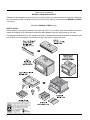
1
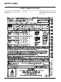
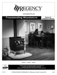
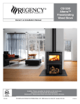
www.regency-fire.com
Freestanding Woodstoves
MODELS:
F1100S
F3100L
Owners &
Installation Manual
S3100L
Tested by:
Installer: Please complete the details on the back cover
and leave this manual with the homeowner.
Homeowner: Please keep these instructions for future reference.
908-288b
FPI FIREPLACE PRODUCTS INTERNATIONAL LTD. 6988 Venture St., Delta, BC Canada, V4G 1H4
02/22/06
Thank-you for purchasing a
REGENCY FIREPLACE PRODUCT.
The pride of workmanship that goes into each of our products will give you years of trouble-free enjoyment. Should you
have any questions about your product that are not covered in this manual, please contact the REGENCY DEALER
in your area.
Keep those REGENCY FIRES burning.
SAFETY NOTES:
If this woodstove is not properly installed, a house fire may result. For your safety, follow the installation instructions,
contact local building or fire officials about restrictions and installation inspection requirements in your area.
This appliance needs fresh air for safe operation and must be installed with adequate combustion air available to the
room in which it is to be operating. Air starvation or icing of the chimney system may result.
2
Regency Freestanding Woodstove
TABLE OF CONTENTS
SAFETY LABEL
Safety Label For F1100S ...............................................4
Safety Label For F3100L ...............................................5
Safety Label For S3100L ...............................................6
PARTS LIST
F1100 & F3100 Stove Main Assembly.........................22
S3100 Step Stove Main Assembly ..............................23
Pedestal, Bottom Shield & Leg Options ......................24
Firebrick .......................................................................25
INSTALLATION
NOTES
Residential ....................................................................7
Installation .....................................................................7
Room Air .......................................................................7
Important .......................................................................7
Modular Installation Options ..........................................7
Minimum Clearance ToCombustible Materials ..............8
WARRANTY
INSTALLATION
Stove Assembly Prior To Installation ...........................10
Step By Step Chimney And Connector Installation ..... 11
MasonryChimney ........................................................12
MasonryFireplace ........................................................12
factory ..........................................................................12
built chimney ...............................................................12
Combustible Wall ChimneyConnector Pass-throughs .13
RecommendedHeights ForWoodstove Flue................14
Mobile Home Installation .............................................14
Listed Components For Mobile Home Installation .......15
Brick Flue Baffle &Secondary Air TubeInstallation ......16
Brick Installation ..........................................................17
Door Handle ................................................................17
Glass Installation .........................................................17
Optional Accessories ...................................................17
Screen Door ................................................................17
Operating Instructions .................................................19
First Fire ......................................................................19
OPERATING INSTRUCTIONS
Draft Control ................................................................19
Fan Operation .............................................................20
Ash Disposal ...............................................................20
Safety Guidelines And Warnings .................................20
Creosote ......................................................................21
Latch Adjustment .........................................................21
Door Gasket ................................................................21
Glass Maintenance ......................................................21
MAINTENANCE
Maintenance ................................................................21
Maintenance OfGold-plated Doors ..............................21
Regency Freestanding Woodstove
3
SAFETY LABEL
SAFETY LABEL FOR F1100S
We have printed a copy of the contents here
for your review.
duplicate serial number
100
C
F
BACK M
FLOOR
PROTECTION*
O
K 405 mm / 16 in
L 150 mm / 6 in
M 150 mm / 6 in
L
K FRONT
MADE IN CANADA
UNITED STATES ENVIRONMENTAL
PROTECTION AGENCY
CERTIFIED TO COMPLY WITH JULY 1990,
PARTICULATE EMISSION STANDARDS.
CAUTION
HOT WHILE IN OPERATION DO NOT TOUCH. KEEP CHILDREN,
CLOTHING AND FURNITURE AWAY. CONTACT MAY CAUSE
SKIN BURNS. READ NAMEPLATE AND INSTRUCTIONS.
908 281a
10/05
4
2007
FPI FIREPLACE PRODUCTS INTERNATIONAL LTD.
6988 VENTURE ST.
DELTA, BC V4G 1H4
2006
* In Canada, floor protection must
extend 18" to the front and 8" to
each side of the stove.
FOR USE WITH SOLID WOOD FUEL ONLY. USE OF OTHER FUELS MAY DAMAGE HEATER AND CREATE A HAZARDOUS CONDITION. DO NOT OBSTRUCT
COMBUSTION AIR OPENINGS. OPERATE ONLY WITH FIREBRICKS IN PLACE. OPERATE ONLY WITH DOOR CLOSED OPEN FEED DOOR TO FEED FIRE ONLY.
DO NOT USE GRATE OR ELEVATE FIRE. BUILD WOOD FIRE DIRECTLY ON HEARTH. DO NOT OVERFIRE IF HEATER OR CHIMNEY CONNECTOR GLOWS
YOU ARE OVERFIRING. INSPECT AND CLEAN CHIMNEY AND CONNECTOR FREQUENTLY. UNDER CERTAIN CONDITIONS OF USE CREOSOTE BUILDUP MAY
OCCUR RAPIDLY. KEEP FURNISHINGS AND OTHER COMBUSTIBLE MATERIAL AWAY FROM HEATER. REPLACE GLASS ONLY WITH NEOCERAM GLASS.
COMBUSTIBLE FLOOR MUST BE PROTECTED BY NON COMBUSTIBLE MATERIAL EXTENDING BENEATH THE HEATER AND TO THE FRONT AND SIDES AS
INDICATED OR TO THE NEAREST PERMITTED COMBUSTIBLE MATERIAL.
OPTIONAL COMPONENT: FAN, ELECTRICAL RATING: VOLTS 115, 60 HZ, 2 AMPS, SCREEN DOOR
COMPONENTS REQUIRED FOR MOBILE HOME INSTALLATION: OUTSIDE AIR KIT AND ONE OF THE FOLLOWING DOUBLE WALL CONNECTOR
IN CANADA: LISTED SECURITY MODEL DP, OR OLIVER MACLEOD PRO VENT PV DOUBLE WALLED CONNECTOR WITH LISTED CHIMNEY SYSTEM:
SECURITY MODEL S2100, ICC EXCEL 2100 .
IN USA: LISTED DOUBLE WALL CONNECTORS SECURITY MODEL DP, SELKIRK MODEL DS, OLIVER MACLEOD PRO VENT PV, SIMPSON DURA VENT
MODEL DVL, GSW SUPER PIPE 6, METAL FAB DOUBLE WALL. CONNECTED TO ONE OF THE FOLLOWING COMPATIBLE CHIMNEY SYSTEMS SECURITY
MODEL S2100 OR MODEL ASHT, SELKIRK MODEL SSII, OLIVER MACLEOD PRO JET 3103, SIMPSON DURA PLUS, GSW MODEL SC OR METAL FAB TEMP/
GUARD, AMERI TEC HS, ICC EXCEL 2100 . USE CHIMNEY COMPONENTS AS SPECIFIED IN INSTALLATION INSTRUCTIONS.
MANUFACTURED BY:
OCT
AUG
JUL
ADJACENT WALL
2005
MINIMUM ALCOVE CEILING HEIGHT: 2.15 M / 7 FT
MAXIMUM ALCOVE DEPTH 915 MM / 36 IN.
MINIMUM CLEARANCES FOR HORIZONTAL CONNECTOR TO CEILING: 455 MM / 18"
THE SPACE BENEATH THE HEATER MUST NOT BE OBSTRUCTED. OPERATE ONLY WITH FIREBRICKS IN PLACE.
I
JUN
INSTALLATION USING LISTED DOUBLE WALL
CONNECTOR ALCOVE
SIDEWALL
G 330 mm / 13 in I 635 mm / 25 in
BACKWALL H 125 mm / 5 in J 290 mm / 11.5in
G
G
MAY
INSTALLATION USING LISTED DOUBLE WALL
CONNECTOR ALCOVE
SIDEWALL
G 280 mm / 11 in I 585 mm / 23 in
BACKWALL H 180 mm / 7 in J 345 mm / 13.5in
J
APR
INSTALLATION USING LISTED DOUBLE WALL
CONNECTOR RESIDENTIAL CLOSE CLEARANCE
SIDEWALL
A 345 mm / 13.5in D 650 mm / 25.5in
BACKWALL B 125 mm / 5 in E 290 mm / 11.5in
CORNER
C 125 mm / 5 in F 430 mm / 17 in
H
MAR
INSTALLATION USING LISTED DOUBLE WALL
CONNECTOR RESIDENTIAL CLOSE CLEARANCE
SIDEWALL
A 230 mm / 9 in D 535 mm / 21 in
BACKWALL B 125 mm / 5 in E 290 mm / 11.5in
CORNER
C 75 mm / 3 in F 380 mm / 15 in
BACKWALL
FEB
INSTALLATION USING LISTED DOUBLE WALL
CONNECTOR MOBILE HOME
SIDEWALL
A 330 mm / 13 in D 635 mm / 25 in
BACKWALL B 125 mm / 5 in E 290 mm / 11.5in
CORNER
C 230 mm / 9 in F 535 mm / 21 in
D
SIDE
INSTALLATION USING LISTED DOUBLE WALL
CONNECTOR MOBILE HOME
SIDEWALL
A 280 mm / 11 in D 585 mm / 23 in
BACKWALL B 150 mm / 6 in E 320 mm / 12.5in
CORNER
C 150 mm / 6 in F 460 mm / 18 in
E
SIDE
MEASURE
FLUE
FROM
HEATER
CENTER LINE
RESIDENTIAL INSTALLATION USING
SINGLE WALL CONNECTOR
SIDEWALL
A 380 mm /15 in D 685 mm / 27 in
BACKWALL B 265 mm / 10.5in E 430 mm / 17 in
CORNER
C 280 mm / 11 in F 585 mm / 23 in
B
A
SIDEWALL
MEASURE
FLUE
FROM
HEATER
CENTER LINE
RESIDENTIAL INSTALLATION USING
SINGLE WALL CONNECTOR
SIDEWALL
A 330 mm / 13 in D 635 mm / 25 in
BACKWALL B 280 mm / 11 in E 445 mm / 17.5in
CORNER
C 205 mm / 8 in F 510 mm / 20 in
SIDEWALL
F1100S WITHOUT AIRMATE SHIELD
SIDEWALL
MINIMUM CLEARANCES TO COMBUSTIBLE MATERIALS
F1100S WITH AIRMATE SHIELD
SIDEWALL
F1100S WITHOUT
F1100S WITH
AIRMATE SHIELD AIRMATE SHIELD
INSTALL AND USE ONLY IN ACCORDANCE WITH THE MANUFACTURER'S INSTALLATION AND OPERATING
INSTRUCTIONS. CONTACT LOCAL BUILDING OR FIRE OFFICIALS ABOUT RESTRICTIONS AND
INSTALLATION INSPECTION IN YOUR AREA. USE 150 MM (6 IN.) DIAMETER MINIMUM 24 MSG BLACK
OR 25 MSG BLUED STEEL CONNECTOR WITH LISTED FACTORY BUILT CHIMNEY SUITABLE FOR USE WITH
SOLID FUELS OR MASONRY CHIMNEY.
SEE LOCAL BUILDING CODE AND MANUFACTURER'S INSTRUCTIONS FOR PRECAUTIONS REQUIRED FOR
PASSING A CHIMNEY THROUGH A COMBUSTIBLE WALL OR CEILING. DO NOT PASS CHIMNEY
CONNECTOR THROUGH COMBUSTIBLE WALL OR CEILING. DO NOT CONNECT THIS UNIT TO A CHIMNEY
BACKWALL
FLUE SERVING ANOTHER APPLIANCE.
SEPT
100
MODEL: REGENCY SMALL FREESTANDING STOVE F1100S
TESTED TO: ULC S627 00 / UL 1482 1998 / UL 737 2000 REPORT NO.6621 (MAY 1993)
NOV
DEC
DO NOT REMOVE THIS LABEL
JAN
LISTED SPACE HEATER, SOLID FUEL TYPE, ALSO
SUITABLE FOR MOBILE HOME INSTALLATION
NOTE: Regency units are constantly being
improved. Check the label on the unit and if
there is a difference, the label on the unit is the
correct one.
DATE OF MANUFACTURE
This is a copy of the label that accompanies
each Regency Small Freestanding Woodstove
(F1100S).
Regency Freestanding Woodstove
SAFETY LABEL
SAFETY LABEL FOR F3100L
This is a copy of the label that accompanies
each Regency Large Freestanding Woodstove
(F3100L).
We have printed a copy of the contents here
for your review.
NOTE: Regency units are constantly being
improved. Check the label on the unit and if
there is a difference, the label on the unit is the
correct one.
102
AUG
JUL
F
BACK M
FLOOR
PROTECTION*
K
405 mm / 16 in
L
150 mm / 6 in
M
150 mm / 6 in
O
L
K FRONT
* In Canada, floor protection must
extend 18" to the front and 8" to
each side of the stove.
MINIMUM CLEARANCE BETWEEN HORIZONTAL CHIMNEY CONNECTOR AND COMBUSTIBLE MATERIALS - 460 MM (18 IN.). CLEARANCE MAY BE REDUCED
BY THE USE OF LISTED PIPE SHIELDS, WALL PROTECTORS OR OTHER MEANS APPROVED BY LOCAL BUILDING OR FIRE OFFICIALS. COMBUSTIBLE
FLOOR MUST BE PROTECTED BY NON-COMBUSTIBLE MATERIAL EXTENDING BENEATH THE HEATER AND TO THE FRONT AND SIDES AS INDICATED OR
TO THE NEAREST PERMITTED COMBUSTIBLE MATERIAL.
FOR USE WITH SOLID WOOD FUEL ONLY. USE OF OTHER FUELS MAY DAMAGE HEATER AND CREATE A HAZARDOUS CONDITION. DO NOT OBSTRUCT
COMBUSTION AIR OPENINGS. OPERATE ONLY WITH FIREBRICKS IN PLACE. OPERATE ONLY WITH DOOR CLOSED - OPEN FEED DOOR TO FEED FIRE ONLY.
DO NOT USE GRATE OR ELEVATE FIRE. BUILD WOOD FIRE DIRECTLY ON HEARTH. DO NOT OVERFIRE - IF HEATER OR CHIMNEY CONNECTOR GLOWS
YOU ARE OVERFIRING. INSPECT AND CLEAN CHIMNEY AND CONNECTOR FREQUENTLY. UNDER CERTAIN CONDITIONS OF USE CREOSOTE BUILDUP MAY
OCCUR RAPIDLY. KEEP FURNISHINGS AND OTHER COMBUSTIBLE MATERIAL AWAY FROM HEATER. REPLACE GLASS ONLY WITH NEOCERAM GLASS.
OPTIONAL COMPONENT: FAN, ELECTRICAL RATING: VOLTS 115, 60 HZ, 2 AMPS, SCREEN DOOR
COMPONENTS REQUIRED FOR MOBILE HOME INSTALLATION: OUTSIDE AIR KIT AND ONE OF THE FOLLOWING DOUBLE WALL CONNECTOR
IN CANADA: LISTED SECURITY MODEL DP, OR OLIVER MACLEOD PRO-VENT PV DOUBLE WALLED CONNECTOR WITH LISTED CHIMNEY SYSTEM:
SECURITY MODEL S2100, ICC EXCEL 2100.
IN USA:
LISTED DOUBLE WALL CONNECTORS SECURITY MODEL DP, SELKIRK MODEL DS, OLIVER MACLEOD PRO VENT PV, SIMPSON DURA VENT
MODEL DVL, GSW SUPER PIPE 6, METAL-FAB DOUBLE WALL. CONNECTED TO ONE OF THE FOLLOWING COMPATIBLE CHIMNEY SYSTEMS SECURITY
MODEL S2100 OR MODEL ASHT, SELKIRK MODEL SSII, OLIVER MACLEOD PRO JET 3103, SIMPSON DURA PLUS, GSW MODEL SC OR METAL-FAB TEMP/
GUARD, AMERI-TEC HS, ICC EXCEL 2100 . USE CHIMNEY COMPONENTS AS SPECIFIED IN INSTALLATION INSTRUCTIONS.
MANUFACTURED BY:
FPI FIREPLACE PRODUCTS INTERNATIONAL LTD.
6988 VENTURE ST.
DELTA, BC V4G 1H4
MADE IN CANADA
UNITED STATES ENVIRONMENTAL
PROTECTION AGENCY
CERTIFIED TO COMPLY WITH JULY 1990,
PARTICULATE EMISSION STANDARDS.
CAUTION
HOT WHILE IN OPERATION DO NOT TOUCH. KEEP CHILDREN,
CLOTHING AND FURNITURE AWAY. CONTACT MAY CAUSE
SKIN BURNS. READ NAMEPLATE AND INSTRUCTIONS.
908-351a
2007
C
2006
ADJACE NT WALL
MAY
JUN
I
2005
ALCOVE INSTALLATION
REQUIRES AIRMATE SHIELD
G
G
SIDE
INSTALLATION USING LISTED DOUBLE WALL
CONNECTOR - ALCOVE
SIDEWALL
G 405 mm / 16 in
I 760 mm / 30 in
BACKWALL H 240 mm / 9.5in
J 405 mm / 16 in
J
APR
INSTALLATION USING LISTED DOUBLE WALL
CONNECTOR - RESIDENTIAL CLOSE CLEARANCE
SIDEWALL
A 405 mm / 16 in
D 760 mm / 30 in
BACKWALL B 240 mm / 9.5in
E 405 mm / 16 in
CORNER
C 215 mm / 8.5in
F 560 mm / 22 in
INSTALLATION USING LISTED DOUBLE WALL
CONNECTOR - RESIDENTIAL CLOSE CLEARANCE
SIDEWALL
A 510 mm / 20 in
D 860 mm / 34 in
BACKWALL B 305 mm / 12 in
E 470 mm / 18.5in
CORNER
C 215 mm / 8.5in
F 560 mm / 22 in
H
MAR
INSTALLATION USING LISTED DOUBLE WALL
CONNECTOR - MOBILE HOME
SIDEWALL
A 510 mm / 20 in
D 860 mm / 34 in
BACKWALL B 305 mm / 12 in
E 470 mm / 18.5in
CORNER
C 255 mm / 10 in
F 595 mm / 23.5in
B AC KWALL
FEB
INSTALLATION USING LISTED DOUBLE WALL
CONNECTOR - MOBILE HOME
SIDEWALL
A 460 mm / 18 in
D 810 mm / 32 in
BACKWALL B 240 mm / 9.5in
E 405 mm / 16 in
CORNER
C 255 mm / 10 in
F 595 mm / 23.5in
D
JAN
MEASURE
FLUE
FROM
HEATER
CENTER-LINE
RESIDENTIAL INSTALLATION USING
SINGLE WALL CONNECTOR
SIDEWALL
A 510 mm / 20 in D 860 mm / 34 in
BACKWALL B 355 mm / 14 in E 520 mm / 20.5 in
CORNER
C 265 mm / 10.5in F 610 mm / 24 in
E
S ID EWALL
MEASURE
FLUE
FROM
HEATER
CENTER-LINE
RESIDENTIAL INSTALLATION USING
SINGLE WALL CONNECTOR
SIDEWALL
A 460 mm / 18 in
D 810 mm / 32 in
BACKWALL B 305 mm / 12 in
E 470 mm / 18.5in
CORNER
C 215 mm / 8.5in
F 560 mm / 22 in
B
A
SIDE
F3100L WITHOUT AIRMATE SHIELD
S ID EWALL
MINIMUM CLEARANCES TO COMBUSTIBLE MATERIALS
F3100L WITH AIRMATE SHIELD
S ID EWALL
F3100L WITHOUT
AIRMATE SHIELD
S ID EWALL
F3100L WITH
AIRMATE SHIELD
INSTALL AND USE ONLY IN ACCORDANCE WITH THE MANUFACTURER'S INSTALLATION AND OPERATING
INSTRUCTIONS. CONTACT LOCAL BUILDING OR FIRE OFFICIALS ABOUT RESTRICTIONS AND INSTALLATION INSPECTION IN YOUR AREA. USE 150 MM (6 IN.) DIAMETER MINIMUM 24 MSG BLACK OR 25 MSG
BLUED STEEL CONNECTOR WITH LISTED FACTORY-BUILT CHIMNEY SUITABLE FOR USE WITH SOLID
FUELS OR MASONRY CHIMNEY.
SEE LOCAL BUILDING CODE AND MANUFACTURER'S INSTRUCTIONS FOR PRECAUTIONS REQUIRED FOR
PASSING A CHIMNEY THROUGH A COMBUSTIBLE WALL OR CEILING. DO NOT PASS CHIMNEY CONNECTOR THROUGH COMBUSTIBLE WALL OR CEILING. DO NOT CONNECT THIS UNIT TO A CHIMNEY FLUE
B AC KWALL
SERVING ANOTHER APPLIANCE.
SEPT OCT
102
MODEL:
REGENCY LARGE FREESTANDING STOVE - F3100L
TESTED TO: ULC S627-00 / UL 1482-1998 / UL 737-2000
REPORT NO.6623 (MAY 93)
NOV
DEC
DO NOT REMOVE THIS LABEL
DATE OF MANUFACTURE
LISTED SPACE HEATER, SOLID FUEL TYPE, SUITABLE FOR
MOBILE HOME INSTALLATION
10/05
Regency Freestanding Woodstove
5
SAFETY LABEL
SAFETY LABEL FOR S3100L
This is a copy of the label that accompanies
each Regency Large Freestanding Step Woodstove (S3100L).
6
We have printed a copy of the contents here
for your review.
NOTE: Regency units are constantly being
improved. Check the label on the unit and if
there is a difference, the label on the unit is
the correct one.
Regency Freestanding Woodstove
INSTALLATION
RESIDENTIAL
INSTALLATION
1) Read all instructions before installing your
Regency Stove. Install and use only in accordance with these installation and operating
instructions. Be aware that local Codes and
Regulations may override some items in this
manual. Check with your local inspector.
2) Select a position for your Regency Stove.
Consult the minimum clearance chart for your
model and set the stove in place. For close
clearance installation use listed double wall
connector systems (refer to Combustible Wall
Chimney Connector Pass - Throughs).
3) To insure vertical alignment, suspend a plumb
bob from the ceiling over the exact center of
your stove flue and mark a spot on the ceiling
to indicate the center of the chimney.
4) Check that the area above the ceiling is clear
for cutting. Re-confirm the clearance from the
stove to combustibles to insure that they are
within the prescribed limits.
5) Install chimney according to chimney manufacturers instructions. The performance of your
woodstove is governed to a very large part by
the chimney system. Too short a chimney can
cause difficult start-up, dirty glass, backsmoking when door is open, and even reduced heat
output. Too tall a chimney may prompt excessive draft which can result in very short burn
times and excessive heat output. The use of an
inexpensive flue pipe damper may be helpful
in reducing excessive draft.
CAUTION: The chimney should be the same
size as the flue outlet on the stove. The chimney
must be listed as suitable for use with solid
fuels. For other types of chimneys check with
your local building code officials. Do not confuse a chimney with a type “B” Venting System
used for gas appliances as suitable for a wood
burning appliance (refer to the Mobile Home
installations section).
6) Mark the location of the pedestal base or legs
on the floor, then move the stove aside and
mark the position of the floor protector.
7) The floor protector must be of non-combustible
material and must extend 16" in front of the
door opening and 6" to the sides and rear of
the unit. Some areas may require a larger size
floor protector. See your local inspector. For
outside air installation refer to Mobile Home
section.
12) A chimney connector cannot pass through an
attic or roof space, closet or similar concealed
space, or a floor, ceiling, wall or partition of
combustible construction. In Canada, if passage through a wall, or partition of combustible
construction is desired, the installation shall
conform to CAN/CSA-B365, Installation Code
for Solid-Fuel-Burning Appliances and Equipment.
13) Your Regency Woodstove is not to be connected
to any air distribution duct.
Emissions from burning wood or gas could
contain chemicals known to the State of California to cause cancer, birth defects or other
reproductive harm.
NOTE: In Canada, floor protection must extend 18" to the front and 8" to each
side of the stove.
8) When the floor protection is complete, position
the stove with the flue collar centered under
the installed chimney.
9) In seismically active areas, Regency recommends that your unit is secured to the floor by
using the bolt down holes inside the pedestal
(the same ones used in Mobile Home installations).
10) For residential installations using "C" Vent
(single wall) the chimney connector must be
at least 24 gauge steel. Do not use galvanized
pipe. For Mobile Home installation refer to the
Mobile Home installation section.
11) Do not connect this unit to a chimney serving
another appliance unless approved by your
local building authority.
ROOM AIR
IMPORTANT
For installation using room air for combustion,
remove knockout from the pedestal, and/or from
the bottom if using a heat shield.
Mobile home installations require the use of outside air.
On pedestal units there are two locations where
outside air may be adapted to the unit. If using the
bottom of the pedestal, do not remove knockout from
the rear of the pedestal. Only remove rear knockout
if outside air will be brought in from the rear.
On leg units outside air can only be brought in from
the bottom of the heat shield.
Note: Once the knockout is removed there are
two tabs remaining. Bend both tabs out
for ease of installation when attaching
outside air.
MODULAR INSTALLATION OPTIONS
The following items are required when assembling your Regency Stove. F1100 and F3100 units - the Rear Heat Deflector is supplied with the
stove, but if you choose not to use it you must use the Airmate instead.
Things to consider when choosing options:
Modular Part
Clearances are different. See the chart on pages 8 and 9. Generally you can get closer clearances with the airmate
F1100 & F3100 only: than with the rear heat deflector.
Airmate OR
Convection heat with Airmate vs. Radiant Heat with Rear Heat Deflector. The airmate pushes heat forward and into
Rear Heat Deflector the room, the rear heat deflector deflects the heat upward. See installation instructions on page 10.
(all units)
Pedestal OR
Legs
There are no performance differences with either the pedestal or legs. It is primarily a personal preference. Legs can
be either painted steel, painted cast, or gold plated cast.
Leg installation requires the bottom shield. See installation instructions on page 11.
OPTIONS: These can be installed at time of installation or added later:
Modular Option
Things to consider when choosing options
Blower/Fan
Adding the blower will increase the area heated by the stove, it can move warm air beyond the room where the stove
is installed. Installation instructions on page 18.
Ash Drawer Kit
Adding the Ash Drawer Kit makes cleaning ashes out of the stove easier and cleaner. Installation instructions on
page 17.
Screen Door
A simple add-on option that will allow you to enjoy the sound, warmth and view of an open fire.
Regency Freestanding Woodstove
7
INSTALLATION
MINIMUM CLEARANCE TO
COMBUSTIBLE MATERIALS
Please read the section below carefully as clearances depend on whether the airmate or the rear heat deflector is installed on the stove.
Measurements "From Unit" are from the top plate of the stove to a side wall or to a corner, and from the rear heat shield to a back wall.
Residential Installation “C” Vent (Single Wall)
Unit
From Unit
From Corner
From Flue Center-line
A
B
C
D
E
F
Small F1100S
with Airmate
with Rear Deflector
13"
15"
11"
10.5"
8"
11"
25"
27"
17.5"
17"
20"
23"
Large F3100L
with Airmate
with Rear Deflector
18"
20"
12"
14"
8.5"
10.5"
32"
34"
18.5"
20.5"
22"
24"
Large S3100L
Step Stove
18"
12"
8.5"
32"
18.5"
22"
Residential Close Clearance (To be installed with required pipe components)
When the stove is installed as a close clearance residential unit, a listed double wall connector is required from the stove
collar to the ceiling level.
Unit
From Unit
From Corner
From Flue Center-line
A
B
C
D
E
F
Small F1100S
with Airmate
with Rear Deflector
9"
13.5"
5"
5"
3"
5"
21"
25.5"
11.5"
11.5"
15"
17"
Large F3100L
with Airmate
with Rear Deflector
16"
20"
9.5"
12"
8.5"
8.5"
30"
34"
16"
18.5"
22"
22"
Large S3100L
Step Stove
16"
9.5"
8.5"
30"
16"
22"
Mobile Home Close Clearance (To be installed with required pipe components)
"C" Vent single wall pipe is not approved for Mobile Home installations. (Refer to Mobile Home Instructions.)
Unit
8
From Unit
From Corner
From Flue Center-line
A
B
C
D
E
F
Small F1100S
with Airmate
with Rear Deflector
11"
13"
6"
5"
6"
9"
23"
25"
12.5"
11.5"
18"
21"
Large F3100L
with Airmate
with Rear Deflector
18"
20"
9.5"
12"
10"
10"
32"
34"
16"
18.5"
23.5"
23.5"
Large S3100L Step Stove
18"
9.5"
10"
32"
16"
23.5"
Regency Freestanding Woodstove
INSTALLATION
Minimum Alcove Clearance to Combustible Materials
The Regency Freestanding models have been alcove approved and must be installed
with a listed double wall connector to the ceiling level.
Note: Minimum alcove ceiling height - 84"
Maximum depth of alcove - 36"
From
Unit
Small F1100S
with Airmate
with Rear Deflector
Large F3100L
with Airmate
with Rear Deflector
Unit
From Flue
Min.
Min.Hearth
Center-line
Width
to Rear Wall
G
H
I
J
K
L
11"
13"
7"
5"
23"
25"
13.5"
11.5"
46"
50"
39"
37"
16"
60"
46.5"
16"
60"
46.5"
16"
9.5"
30"
(not approved for Alcove)
Large S3100L Step Stove
16"
9.5"
30"
Floor Protection
A combustible floor must be protected by a non-combustible material (like tile,
concrete board, or certified to UL-1618 or as defined by local codes) extending beneath the heater and a minimum of 6" from each side and minimum
16" from the front face of the stove and minimum 6" (or the rear clearance to
combustibles whichever is smaller) from the rear of the stove.
Minimum Overall Width (X) of Floor
Protector for all installations:
Small Stove
F1100S
36"
Large Stove
F3100L
40"
Large Step Stove
S3100L
40"
NOTE: In Canada, floor protection must extend 18" to the front and 8" to each side of the stove.
Minimum Overall Depth (Y) of Floor Protector
Unit
Residential
Residential
"C" Vent
Close Clearance
Mobile Home
Alcove
Y
Z
Y
Z
Y
Z
Y
Z
Close Clearance
Small F1100S
with Airmate
with Rear Deflector
38"
38"
6"
6"
37"*
37"*
5"
5"
38"
37"*
6"
5"
38"
37"*
6"
5"
Large F3100L
with Airmate
with Rear Deflector
43"
43"
6"
6"
43"
43"
6"
6"
43"
43"
6"
6"
43"
n/a
6"
n/a
Large S3100L
Step Stove
43"
6"
43"
6"
43"
6"
43"
6"
*The rear clearance to combustibles is less than 6" (152mm), for corner installations the rear corners may be angled to take advantage of the
closer clearances.
Regency Freestanding Woodstove
9
INSTALLATION
Pedestal Assembly
STOVE ASSEMBLY
PRIOR TO
INSTALLATION
Rear Heat Deflector Assembly
for F1100 & F3100
All units require either the pedestal or 4 legs attached to the base. The F1100 and F3100 stoves
require either the Airmate or Rear Heat Deflector
on top of the stove. Clearances to combustible
materials vary depending on whether the airmate
or rear heat deflector is installed, so be sure to
check the Minimum Clearance to Combustible
Materials section.
The rear heat deflector is supplied with the stove
and must be installed unless the optional airmate
has been selected. It stops the heat radiated from
the flue collar from overheating the rear wall. The
rear heat deflector is installed on top of the rear
heat shield, as shown in Diagram 4.
Small
Large
815-555
815-556
850-115
850-315
1) For easier assembly, tip the stove on its
back (onto a soft surface to prevent scratching).
Hint: If you have chosen the Ash Drawer
option, remove the ash dump cover plates
before attaching the pedestal (refer to the
Ashdrawer Kit Installation section).
2) Remove the blanking plate if:
a) you are not installing outside combustion
air or
b) outside air is to be brought in from the
rear of the stove.
Airmate Assembly
for F1100 & F3100
Small
Large
Small
Large
3) Unscrew the 4 bolts in the under-side of the
stove. Align the holes in the corners of the
pedestal top with the corresponding holes
in the base of the stove. Fasten using a bolt
and washer for each corner.
850-105
850-305
1) The airmate sits on top of the stove with
the slots in the sides fitting over the curved
deflector on the rear stove top. See diagram
1. Discard the Rear Heat Deflector that is
supplied with the unit, it is not required if the
airmate is installed.
2) Center the airmate and push it forward to the
front of the stove. The back of the airmate
should be level with the back and sides of
the rear heat shield. See Diagrams 2 & 3.
Diagram 4
S3100L Side Shield Adjustment
The left and right side shields are lowered for
shipping and handling. It allows for a handhold
on the top of the stove. Before placing in the
Step Stove in its final position, the side shields
must be raised.
Loosen the screws on the rear on the stove (3 per
side), slide the side panel up as far as possible
and then secure by tightening the screws.
Diagram 1
4) Push the Regency logo
into the two holes in
the front bottom left corner
of the pedestal
cover plate.
Diagram 2
Note: Any paint touch up should be done
prior to placing logo on pedestal.
Diagram 3
10
5) If not using ash drawer, then cover plate must
be installed. If using ash drawer, then disregard
cover plate.
Regency Freestanding Woodstove
INSTALLATION
Leg and Bottom Shield Assembly
Bottom Shield
Small
Large
Legs (set of 4)
Steel - Painted Black
Cast - Painted Black
Cast - Gold Plated
850-121
850-321
850-125
850-126
850-127
The instructions below apply to the steel leg,
painted cast leg and the gold plated cast leg. It
will be easier to attach the legs to the stove if
the stove is tipped on its back (preferably on a
soft surface to prevent scratching). Ensure to be
extremely careful when tipping stove.
STEP BY STEP
CHIMNEY AND
CONNECTOR
INSTALLATION
Note: These are a generic set of chimney
installation instructions. Always follow the manufacturers own instructions explicitly. Check the Minimum
Recommended Flue Heights section
(Table 1).
1) Remove the 4 bolts from underside of the
base of the pedestal and discard. Also
remove cover plate and put to the side.
1) With your location already established, cut
and frame the roof hole. It is recommended
that no ceiling support member be cut for
chimney and support box installation. If it is
necessary to cut them, the members must
be made structurally sound.
2) Line up the heat shield with the bottom of
the unit.
2) Install radiant shield and support from
above.
3) Start threading the bolt and washer (supplied
with the bottom shield) for about 1/4 of the
way through the leg with the washers being
underneath the legs. Ensure that the legs
are properly aligned with heat shield and
tighten the bolts.
3) Stack the insulated pipe onto your finish
support to a minimum height of 3 feet above
the roof penetration, or 2 feet above any
point within 10 feet measured horizontally.
There must be at least 3 feet of chimney
above the roof level.
8) To complete your chimney installation, install
the double wall connector pipe from the
stove’s flue collar to the chimney support
device.
9) If you are using a horizontal connector,
the chimney connector should be as high
as possible while still maintaining the 18"
(457mm) minimum distance from the horizontal connector to the ceiling.
10) NOTE: Residential Close Clearance and
Alcove installations require a listed double wall connector from the stove collar
to the ceiling level.
The diagrams below illustrate one way to install your unit into a standard ceiling or with a
horizontal connector. Check with your dealer
or installer for information on other options
available to you.
4) Level the stove by adjusting the levelling
bolts in the bottom of each leg.
Note: Increasing the chimney height above
this minimum level will sometimes
help your unit to “breathe” better
by allowing a greater draft to be created. This greater draft can decrease
problems such as, difficult start-ups,
back-smoking when door is open, and
dirty glass. It might be sufficient to
initially try with the minimum required
height, and then if problems do arise
add additional height at a later date.
Standard Ceiling Installation
4) Slide the roof flashing over your chimney
and seal the flashing to the roof with roofing
compound. Secure the flashing to your roof
with nails or screws.
5) Reinstall cover plate.
6) Install logo plate onto heat shield by placing
in 2 holes as shown in diagram.
If you are installing outside combustion air, bend
the tabs out 90 degrees. Pipe fresh air into the
bottom shield by using a minimum 4" duct pipe
with a mesh grill at the outside termination. Attach the pipe to the 2 tabs with screws.
Regency Freestanding Woodstove
5) Place the storm collar over the flashing,
sealing the joints with a silicone caulking.
6) Fasten the raincap with spark screens (if
required) to the top of your chimney.
7) For optimum efficiency when installing into
a masonry chimney, size accordingly, i.e.
the 6" (152mm) flue dia. is 28.28 sq.in.
Horizontal Installation
11
INSTALLATION
MASONRY
CHIMNEY
Ensure that a masonry chimney meets the minimum standards of the National Fire Protection
Association (NFPA) by having it inspected by
a professional. Make sure there are no cracks,
loose mortar or other signs of deterioration and
blockage. Have the chimney cleaned before
the stove is installed and operated. When
connecting the stove through a combustible
wall to a masonry chimney, special methods
are needed.
Ensure that an effective vapour barrier at the
location where the chimney or other component
penetrates to the exterior of the structure.
When referencing installation or connection to masonry fireplaces or chimneys, the
masonry construction must or shall be code
complying.
MASONRY
FIREPLACE
There are listed kits available to connect a stove
to a masonry fireplace. The kit is an adapter
that is installed at the location of the fireplace
damper. The existing damper may have to be
removed to allow installation.
Ensure that an effective vapour barrier at the
location where the chimney or other component
penetrates to the exterior of the structure.
When referencing installation or connection to masonry fireplaces or chimneys, the
masonry construction must or shall be code
complying.
FACTORY
BUILT CHIMNEY
When a metal prefabricated chimney is used, the manufacturer's installation instructions must be followed. You must also purchase and install the
ceiling support package or wall pass-through and "T" section package, firestops (where needed), insulation shield, roof flashing, chimney cap, etc.
Maintain proper clearance to the structure as recommended by the manufacturer. The chimney must be the required height above the roof or other
obstructions for safety and proper draft operation. The space heater is to be connected to a factory-built chimney conforming to CAN/ULC-S629,
Standard for 6500C Factory-Built Chimneys.
12
Regency Freestanding Woodstove
INSTALLATION
COMBUSTIBLE WALL CHIMNEY
CONNECTOR PASS-THROUGHS
Method A: 12" (304.8 mm) Clearance to Combustible Wall Member:
Using a minimum thickness 3.5" (89 mm) brick and a 5/8" (15.9 mm)
minimum wall thickness clay liner, construct a wall pass-through. The
clay liner must conform to ASTM C315 (Standard Specification for
Clay Fire Linings) or its equivalent. Keep a minimum of 12" (304.8
mm) of brick masonry between the clay liner and wall combustibles.
The clay liner shall run from the brick masonry outer surface to the
inner surface of the chimney flue liner but not past the inner surface.
Firmly grout or cement the clay liner in place to the chimney flue liner.
Method B: 9" (228.6 mm) Clearance to Combustible Wall Member:
Using a 6" (152.4 mm) inside diameter, listed, factory-built Solid-Pak
chimney section with insulation of 1" (25.4 mm) or more, build a wall
pass-through with a minimum 9" (228.6 mm) air space between the
outer wall of the chimney length and wall combustibles. Use sheet metal
supports fastened securely to wall surfaces on all sides, to maintain the
9" (228.6 mm) air space. When fastening supports to chimney length,
do not penetrate the chimney liner (the inside wall of the Solid-Pak
chimney). The inner end of the Solid-Pak chimney section shall be
flush with the inside of the masonry chimney flue, and sealed with a
non-water soluble refractory cement. Use this cement to also seal to
the brick masonry penetration.
Method C: 6" (152.4 mm) Clearance to Combustible Wall Member:
Starting with a minimum 24 gage (.024" [.61 mm]) 6" (152.4 mm) metal
chimney connector, and a minimum 24 gage ventilated wall thimble
which has two air channels of 1" (25.4 mm) each, construct a wall
pass-through. There shall be a minimum 6" (152.4) mm separation area
containing fiberglass insulation, from the outer surface of the wall thimble
to wall combustibles. Support the wall thimble, and cover its opening
with a 24-gage minimum sheet metal support. Maintain the 6" (152.4
mm) space. There should also be a support sized to fit and hold the
metal chimney connector. See that the supports are fastened securely
to wall surfaces on all sides. Make sure fasteners used to secure the
metal chimney connector do not penetrate chimney flue liner.
Method D: 2" (50.8 mm) Clearance to Combustible Wall Member:
Start with a solid-pak listed factory built chimney section at least 12"
(304 mm) long, with insulation of 1" (25.4 mm) or more, and an inside
diameter of 8" (2 inches [51 mm] larger than the 6" [152.4 mm] chimney
connector). Use this as a pass-through for a minimum 24-gage single
wall steel chimney connector. Keep solid-pak section concentric with
and spaced 1" (25.4 mm) off the chimney connector by way of sheet
metal support plates at both ends of chimney section. Cover opening
with and support chimney section on both sides with 24 gage minimum
sheet metal supports. See that the supports are fastened securely to
wall surfaces on all sides. Make sure fasteners used to secure chimney
flue liner.
Regency Freestanding Woodstove
13
INSTALLATION
TABLE 1
MINIMUM RECOMMENDED FLUE HEIGHTS IN FEET
(Measured from the top of the unit)
# OF ELBOWS
ELEVATION (FT)
ABOVE SEA LEVEL
0
0-1000
1000-2000
2000-3000
3000-4000
4000-5000
5000-6000
6000-7000
7000-8000
8000-9000
9000-10000
12.0
12.5
13.0
13.5
14.0
14.5
15.0
15.5
16.0
16.5
2 x 15o 4 x 15o 2 x 30o
13.0
13.5
14.0
14.5
15.0
15.5
16.0
16.5
17.0
17.5
14.0
14.5
15.0
15.5
16.0
17.0
17.5
18.0
18.5
19.0
15.0
15.5
16.0
17.0
17.5
18.0
18.5
19.0
20.0
20.5
4 x 30o 2 x 45o 4 x 45o
18.0
19.0
19.5
20.0
21.0
21.5
22.5
23.0
24.0
24.5
16.0
16.5
17.0
18.0
18.5
19.0
20.0
20.5
21.0
22.0
20.0
21.0
21.5
22.5
23.0
24.0
25.0
25.5
26.5
27.0
NOTE: No more than two offsets (four elbows) allowed. Two 45o elbows equal one 90o elbow.
RECOMMENDED
HEIGHTS FOR
WOODSTOVE FLUE
Simple rules on draft. See Table 1.
1) At sea level minimum height is 12'
straight.
2) Add the following vertical height to compensate for:
45 deg. elbow = 1 ft.
90 deg. elbow = 2 ft.
"T"
= 3 ft.
Each foot of horizontal run = 2 ft.
3) Add 4% overall for each 1000' above sea
level.
Example: a)
1-1/2 ft. of horizontal run
one "T"
Total Addition (at sea level)
= 3 ft.
= 3 ft.
= 6 ft.
Example: b)
One 90 deg. elbow
2 ft. of horizontal run
one "T"
Total Addition (at sea level)
= 2 ft.
= 4 ft.
= 3 ft.
= 9 ft.
Recommended Flue Height
Elevation Example a)
Example b)
0'
18'
21'
1000'
18.72'
21.84'
2000'
19.44'
22.68'
5000'
21.60'
25.20'
8000'
23.76'
27.72'
14
MOBILE HOME INSTALLATION
Once you have properly marked the position
of your unit and the floor protection as outlined
in the Residential Installation items #1 through
#8, a supply of fresh air has to be supplied to
your unit. Cut a minimum 4 inch diameter hole
through your floor protector and the floor directly
under your pedestal base to the outside. Use
4" duct pipe with a mesh grill to pipe fresh air
into the pedestal area. Block off the hole in the
back of the pedestal with the square plate and
the two 1/2" screws provided.
Place your unit in position and secure it to the
floor using two lag bolts 3/8" x 3-1/2" through
the two holes inside the pedestal base. It is
important to maintain the structural integrity
of the Mobile Home floor, walls and roof when
installing your unit.
For Mobile Home units installed in the U.S. the
unit must be grounded using a #8 ground wire
with approved termination and star washer.
WARNING:
Minimum height requirements
must be met. Safe removal of
the chimney system must be
adhered to when transporting the
mobile home.
WARNING: Operate only with door fully
closed - open feed door to feed fire only.
Regency Freestanding Woodstove
INSTALLATION
LISTED COMPONENTS FOR
MOBILE HOME INSTALLATION
The Regency Small and Large Freestanding pedestal units are approved for installation in a Mobile Home if one of the following pipe systems is
used.
U.S. Installation*
METALBESTOS SSII
Qty. Part #
Description
1 6DS-VK
Connector Kit
1 6TMH
Shield/Support
1 6TAF-6
Flashing
1 6T-36
Chimney Length
1 6T-18
Chimney Length
1 6T-CT
Rain Cap
PRO-JET 3103
Qty.Part #
1 PV06-TK
1 CSB
1 RRS
1 LFR03
1 SL3
1 SL1
1 RCSA
Description
Connector
Shield/Support
Radiation Shield
Flashing
Chimney Length
Chimney Length
Rain Cap
SECURITY ASHT
Qty.Part #
Description
1 DL42A-6
Connector Kit
1 6SS
Shield/Support
1 6FAMH
Flashing
1 6L3
Chimney Length
1 6L1
Chimney Length
1 CPE
Rain Cap
AMERI-TEC HS
Qty.Part #
Description
1 6DCC
Connector
1 6HSRS-12 Roof Support (6PLRS-12-BK)
1 6F
Flashing
1 6HS-36
Chimney Length
1 6HS-18
Chimney Length
1 6HS-RCS Rain Cap (6PL-MPC)
SIMPSON DURA-PLUS
Qty.Part #
Description
1 6DVL8693 Connector Kit
1 6DP-MH9096 Mobile Home Kit
ICC EXCEL 2100
Qty.Part #
Description
1 6CL48
48" Chimney length (also in
12",18", 24" lengths.
1 6RC
Rain Cap
1 6RCS
Spark Screen (for rain cap)
1 6RDS/SQS Round/Square support box
1 6VF
Flashing
1 6UBA
"Ultrablack" Close Clearance
Connector
Canadian Installations*
SECURITY S2100 (see above for details)
ICC EXCEL 2100 (see above for details)
*The use of alternate pitch flashings, support
box extensions, additional chimney lengths,
and additional chimney bracing, may be used
on each of the previously listed systems. These
parts though must be from the same system
as listed, and must be a similar and/or complimentary part.
CAUTION: At no time use unlabelled
parts, or substitute parts made for
another chimney system.
Install as per chimney manufacturer's installation instructions.
SECURITY S2100
Qty.Part #
Description
1 DL42A-6
Connector Kit
1 6XSF
Support
1 6XFA
Flashing
1 6XL3
Chimney Length
1 6XL18
Chimney Length
1 6XCPE
Rain Cap
METAL-FAB TEMP/GUARD 2100
Qty.Part #
Description
1 6DWBK
Connector
1 6TGRS
Roof Support
1 6TGG36
Chimney Length
1 6TGG12
Chimney Length
1 6TGF
Flashing
1 6TGC
Rain Cap
Regency Freestanding Woodstove
15
INSTALLATION
Small Stoves F1100S
BRICK FLUE BAFFLE &
SECONDARY AIR TUBE
INSTALLATION
The flue baffle system located in the upper area
of the firebox is removable to make cleaning
your chimney system easier. The brick baffles
must be installed prior to your first fire. Smoke
spillage and draft problems may occur if the
baffles are improperly positioned. Check the
position of the brick baffles on a regular basis as
they can be dislodged if too much fuel is forced
into the firebox.
3) Important: push both baffle bricks so
they are tight against the side walls.
The Large Stoves F3100L and S3100L are
shipped with two of the secondary air tubes
loose inside the firebox. They need to be installed
after the brick baffle are installed. Follow the
directions below.
2) Slide the left baffle brick over the front air
tube and then slide it back over the rear air
tube.
Large Stoves F3100L and S3100L
Front View
The unit arrives with the first two air tubes (from
the front) and the 2 baffle bricks on the floor of
the firebox. The baffle bricks are positioned first
and then the air tubes are installed.
4) Install the two front air tubes into the holes
on the side channels. The notch goes on
the right hand side with the air holes facing
forward toward the door opening. If the tube
will not slide in easily, simply use a pair of
vise grips or pliers and tap it into place with
a hammer. A tighter fit will ensure the tube
will not move when the unit is burning.
NOTE: If the first 2 airtubes are already
installed in the stove, they must be
removed in order to install the Brick
Baffles.
1) If the two air tubes are installed continue on
to Step 2), if not, follow the instructions below.
Install the air tube into the holes in the side
channels. The notch goes on the right hand
side with the air holes facing toward the door.
Slide the tube into the left hand side, as far
as possible and then bring it back into the
hole on the right hand side until it locks into
position. If the tube will not slide in easily
simply use a pair of vise grips or pliers and
tap it into place with a hammer. A tighter fit
will ensure the tube will not move when the
unit is burning. Refer to the Mobile Home
Installation section, though there are only
two air tubes in the small units.
Side View
3) Tilt the left baffle brick up on top of the side
channel and it will leave enough room to
position the right baffle brick in the same
manner as Step 1 above. Then reposition
the left baffle brick flat on the air tube.
1) Slide the left baffle brick over the two rear
air tubes and then push it all the way to the
left side of the firebox.
Side View
Note: When cleaning the chimney reverse
the above procedures, removing
the air tube and baffle bricks and
then replace them when cleaning is
completed.
2) Tilt the first Baffle Brick down and then slide
the 2nd Baffle Brick up and back. Reposition
both baffle bricks flat on the air tubes.
16
Front View
4) Important: push both baffle bricks so
they are tight against the side walls.
Front View
Note: When getting the chimney cleaned,
remove the baffle bricks for access
to the flue, then replace them when
cleaning is completed.
Regency Freestanding Woodstove
INSTALLATION
BRICK INSTALLATION
Pedestal Ash Drawer Kit (850-100)
Firebrick is included to extend the life of your
stove and radiate heat more evenly. Check to
see that all firebricks are in their correct positions and have not become misaligned during
shipping.
1) Remove the bricks from the floor of the
firebox.
The "AD" brick in the drawings above is the
brick covering the Ash Dump hole that is used
when the Ash Drawer Kit is installed (refer to
the Listed Components for Mobile Home Installation section).
2) If using ashdrawer, discard cover plate.
Handle at 10 o'clock position.
NOTE: The handle must be positioned at 10
o'clock when closed to avoid the handle from
getting hot and to ensure the screen stays in
place.
DOOR HANDLE
Attach spring handle by rotating counter
clockwise onto rod. Ensure that the rod fits
into the entire length of the spring handle. See
Diagram below.
3) Remove the ash dump cover plates (one
inside the firebox and one on the underside
of the firebox) by removing the two nuts
and bolts holding the 2 plates together from
inside the firebox.
4) Push the ash plug into the hole inside the
firebox and replace all the bricks except
for the brick over the ash plug. See brick
diagrams.
5) Place the ash drawer lid inside the pedestal,
and the ash plug tool beside the lid, then
slide the ash drawer inside so it sits on top
of the lid.
Freestanding - Small F1100
Refer to the Ash Drawer Operating section.
GLASS INSTALLATION
Your Regency stove is supplied with 5 mm
Neoceram ceramic glass that will withstand
the highest heat that your unit will produce. In
the event that you break your glass by impact,
purchase your replacement from an authorized
Regency dealer only.
Freestanding - Large F3100
SCREEN DOOR
Remove the door from the stove and remove
the glass retainer. Position the glass in the door,
make sure that the glass gasketing will properly
seal your unit, and replace the retainer, it should
rest on the gasket not the glass. Tighten securely,
but do not wrench down on the glass as this may
cause the glass to break.
Hook screen to the inside on the right side
of the firebox door opening. Lock in place by
turning handle.
Bottom Shield Ash Drawer Kit
(850-101 )
1) Remove the bricks from the floor of the
firebox.
2) Remove and discard the cover plate by
removing the two screws on the front of the
Bottom Shield.
3) Remove the ash dump cover plates (one
inside the firebox and one on the underside
of the firebox) by removing the two nuts
and bolts holding the 2 plates together from
inside the firebox.
4) Push the ash plug into the hole inside the
firebox and replace all the bricks except
for the brick over the ash plug. See brick
diagrams.
5) Place the ash plug tool beside the lid, then
slide the ash drawer inside.
OPTIONAL
ACCESSORIES
Hooks
Handle Lock
Back Side of Screen Shown
Regency Freestanding Woodstove
The pieces listed below can be purchased and
installed during the initial installation or added
on later.
Refer to the Ash Drawer Operating section.
17
INSTALLATION
Blower/Fan (846-515)
1) Remove the two screws from the top of the
fan housing.
2) Slide the fan up into the rear heat shield.
3) After aligning holes, secure the fan to the rear
heat shield using the two screws removed
earlier.
Note: The connection cord should not be
in contact with any hot surfaces.
NOTE: This appliance, when installed, must
be electrically grounded in accordance
with local codes or, in the absence of local
codes, with the National Electrical Code,
ANSI/NFPA 70, or the Canadian Electrical
code, CSA C22.1.
Read the operating instructions for the fan
before using.
Neutral
Live
Fan
Switch
Black
Black
High (Black)
Black
Fan
Low (Red)
Fan Thermodisc
(normally open)
Manual/
Auto
Switch
Green
White
120V AC
60 Hz
Ground
Fan
Ground
Blower/Fan Wiring Diagram
WARNING: Electrical Grounding Instructions
This appliance is equipped with a three pronged
(grounding) plug for your protection against shock
hazard and should be plugged directly into a properly
grounded three-prong receptacle. Do not cut or remove
the grounding prong from this plug.
18
CAUTION: Label all wires prior to disconnection
when servicing controls. Wiring errors can cause
improper and dangerous operation.
Regency Freestanding Woodstove
OPERATING INSTRUCTIONS
OPERATING
INSTRUCTIONS
good updraft in the flue to establish the fire.
(Leaving the door slightly open will help your
fire start more rapidly.)
With your unit now correctly installed and safety
inspected by your local authority, you are now
ready to start a fire. Before establishing your
first fire, it is important that you fully understand
the operation of your draft control.
CAUTION: Never leave unit unattended
if door is left open. This procedure is for
fire start-up only, as unit may overheat if
door is left open for too long.
3) With the draft still in the fully open position
add two or three seasoned logs to your fire.
Form a trench in the ash bed to allow air to
reach the rear of the firebox prior to closing
the door.
WARNING
Fireplace Stoves equipped with doors
should be operated only with doors fully
closed. If doors are left partly open,
gas and flame may be drawn out of the
fireplace stove opening, creating risks
from both fire and smoke.
4) After about 15 to 20 minutes, when your
wood has begun to burn strongly, adjust
your draft control down to keep the fire at a
moderate level.
When operated with doors open the
manufacturer supplied screen must
be used.
WARNING: Never build a roaring fire in
a cold stove. Always warm your stove
up slowly!
DRAFT CONTROL
5) Once a bed of coals has been established,
you may adjust the draft control to a low
setting to operate the unit at its most efficient
mode.
Both the primary and air wash drafts are controlled by the control rod located on the left side
of the unit (when facing the unit). To increase
your draft - pull open, and to decrease - push
closed. All units have a secondary draft system
that continually allows combustion air to the
induction ports at the top of the firebox, just
below the flue baffle.
6) During the first few fires, keep the combustion
rate at a moderate level and avoid a large fire.
Only after 5 or 6 such fires can you operate
the stove at its maximum setting, and only
after the metal has been warmed.
Important: If you are using room air for combustion, make sure that the back cover plate
at the rear of the pedestal is not installed. The
cover plate must be installed on the unit if your
stove is located in a mobile home or if using
outside air.
Pull - Open
Push - Closed
WARNING: To build a fire in ignorance or to
disregard the information contained in this
section can cause serious permanent damage to the unit and void your warranty!!
FIRST FIRE
When your installation is completed and inspected you are ready for your first fire.
7) For the first few days, the stove will give off an
odour from the paint. This is to be expected
as the high temperature paint becomes seasoned. Windows and/or doors should be left
open to provide adequate ventilation while
this temporary condition exists. Burning the
stove at a very high temperature the first few
times may damage the paint. Burn fires at
a moderate level the first few days.
8) Do not place anything on the stove top during the curing process. This may result in
damage to your paint finish.
9) During the first few days it may be more
difficult to start the fire. As you dry out your
firebrick and your masonry flue, your draft
will increase.
13) All fuel burning appliances consume oxygen
during operation. It is important that you
supply a source of fresh air to your unit
while burning. A slightly opened window is
sufficient for the purpose. If you also have
a fireplace in your home, a downdraft may
be created by your Regency Stove causing
a draft down your chimney. If this occurs,
slightly open a window near your unit.
CAUTION: If the body of your unit,
flue baffle or any part of the chimney connector starts to glow, you
are overfiring. Stop loading fuel
immediately and close the draft control until the glow has completely
subsided.
14) Green or wet wood is not recommended for
your unit. If you must add wet or green fuel,
open the draft control fully until all moisture
has been dispersed by the intense fire.
Once all moisture has been removed, the
draft control may be adjusted to maintain
the fire.
15) If you have been burning your stove on a low
draft, use caution when opening the door.
After opening the damper, open the door
a crack, and allow the fire to adjust before
fully opening the door.
16) The controls of your unit or the air supply
passages should not be altered to increase
firing for any reason.
17) If you burn the unit too slowly or at too low
a setting your unit will not be operating as
efficiently as it can. An easy rule of thumb
says that if your glass is clean, then your flue
is clean and your exhaust is clean. Burn the
stove hot enough to keep your glass clean
and you won't need to clean your flue as
often.
NOTE: If using a smoke detector, select an
area in the room where the appliance
is located that will not prematurely set
off the smoke detector.
10) For those units installed at higher elevations
or into sub-standard masonry fireplaces,
drafting problems may occur. Consult an
experienced dealer or mason on methods
of increasing your draft.
11) Some cracking and popping noises may be
experienced during the heating up process.
These noises will be minimal when your unit
reaches temperature.
1) Open control fully.
2) Open firebox door and build a small fire
using paper and dry kindling. Secure door
on the firebox and wait a few minutes for a
Regency Freestanding Woodstove
12) Before opening your door to reload, open
draft fully for approximately 10 to 15 seconds
until fire has been re-established. This will
minimize any smoking.
19
OPERATING INSTRUCTIONS
ASH DISPOSAL
During constant use, ashes should be removed
every few days. The Ash Drawer option features
a convenient ash dump for easy removal of ash,
refer to the "Modular Options" section.
Bottom Shield (with Legs) Units:
To remove the drawer, lift slightly and slide
it out, and carry it away.
9) Do not connect this unit to a chimney flue
serving another appliance.
Safety Precautions
1) Do not allow ashes to build up to the loading
doors! Only remove ashes when the fire has
died down. Even then, expect to find a few
hot embers.
2) Please take care to prevent the build-up of
ash around the start-up air housing located
inside the stove box, under the loading door
lip.
3) Never start a fire if the ash plug and ash
drawer are not in place. This will cause
overfiring which can cause excessive warping of the stove. Evidence of overfiring can
void the warranty on your stove.
4) The firebricks are brittle and can be damaged
if the plug is replaced carelessly or pieces
that are too large are forced through the
hole.
Ash Drawer Operating Guideline
1) Only clean ashes out of the stove when the
unit has cooled down. Remove the plug by
lifting on the handle using the tool provided.
The plug may still be warm, use caution.
Push the ashes down the hole into the ash
drawer, the large pieces can be left in the
firebox and burned during the next fire or
removed through the door opening.
4) When emptying the ash drawer, make sure
the ashes are cold. Ashes should be placed
in a metal container with a tight fitting lid.
The closed container of ashes should be
placed on a non - combustible floor or on
the ground, well away from all combustible
materials, pending final disposal. If the ashes
are disposed of by burial in soil or otherwise
locally dispersed, they should be retained in
the closed container until all cinders have
thoroughly cooled. Other waste should not
be placed in the ash container.
5) Before putting the ash drawer back into
place, make sure the ash plug is back in
place.
Pedestal Units: make sure the cover lid is
off.
SAFETY GUIDELINES
AND WARNINGS
1) Never use gasoline, gasoline type lantern
fuels, kerosene, charcoal lighter fuel, or
similar liquids to start or ‘freshen up’ a fire
in your heater. Keep all such liquids well
away from the heater while it is in use.
2) Keep the door closed during operation and
maintain all seals in good condition.
3) Do not burn any quantities of paper, garbage, and never burn flammable fluids such
as gasoline, naptha or engine oil in your
stove.
4) If you have smoke detectors, prevent smoke
spillage as this may set off a false alarm.
2) Always leave 1/2 to 1 inch of ash in the
bottom of the firebox. This helps in easier
starting and a more uniform burn of your
fire. Replace ash plug when ashes have
been removed.
3) Pedestal Units:
To remove the drawer, lift slightly and slide
it out. When the drawer is completely out,
slide the cover plate over the ash drawer
and carry away.
5) Do not overfire heater. If the chimney connector, flue baffle or the stove top begin to
glow, you are overfiring. Stop adding fuel and
close the draft control. Overfiring can cause
extensive damage to your stove including
warpage and premature steel corrosion.
Overfiring will void your warranty.
6) Do not permit creosote or soot build-up
in the chimney system. Check and clean
chimney at regular intervals. Failure to do
so can result in a serious chimney fire.
7) Your Regency stove can be very hot. You
may be seriously burned if you touch the
stove while it is operating, keep children,
clothing and furniture away. Warn children
of the burn hazard.
20
8) The stove consumes air while operating,
provide adequate ventilation with an air
duct or open a window while the stove is in
use.
10) Do not use grates or andirons or other
methods for supporting fuel. Burn directly
on the bricks.
11) Open the draft control fully for 10 to 15
seconds prior to slowly opening the door
when refuelling the fire.
12) Do not connect your unit to any air distribution duct.
13) Your woodstove should burn dry, standard
firewood only. The use of cut lumber,
plywood, “mill ends”, coal, charcoal etc. is
prohibited as this fuel can easily overheat
your woodstove. Evidence of excessive
overheating will void your warranty. As well,
a large portion of sawmill waste is chemically
treated lumber, which is illegal to burn in
many areas. Salt drift wood and chemically
treated fire logs also must not be burned in
your woodstoves.
14) Do not store any fuel closer than 2 feet
from your unit. Do not place wood, paper,
furniture, drapes or other combustibles near
the appliance.
15) WARNING: Do not operate without either
the Ash Plug properly seated or the Ash
Dump Plates screwed in place, excessive
temperatures will result.
16) Do not operate with broken glazing.
FAN OPERATION
Automatic
To operate the fan automatically, push the bottom
switch on the side of the fan housing to "AUTO"
and the top switch to either "HIGH" or "LOW"
for fan speed.
This will allow the fan to turn on as the stove
has come up to operating temperature. It will
also shut the fan system off after the fire has
gone out and the unit cooled to below a useful
heat output range.
Manual
To manually operate the fan system push the bottom switch to "MAN" and the top switch to either
"HIGH" or "LOW". This will bypass the sensing
device and allow full control of the fan.
Switching from "AUTO" to "MAN" or "HIGH" to
"LOW" may be done anytime.
Regency Freestanding Woodstove
MAINTENANCE
MAINTENANCE
It is very important to carefully maintain your
fireplace stove, including burning seasoned
wood and maintaining a clean stove and chimney system. Have the chimney cleaned before
the burning season and as necessary during
the season, as creosote deposits may build up
rapidly. Moving parts of your stove require no
lubrication.
CREOSOTE
When wood is burned slowly, it produces tar and
other organic vapours, which when combined
with moisture, form creosote. The creosote vapours condense in the relatively cool chimney
flue of a slow burning fire. As a result, creosote
residue accumulates on the flue lining. When
ignited, this creosote can result in an extremely
hot fire.
WARNING: Things to remember in case of a
chimney fire:
1. Close all draft and damper controls.
2. CALL THE FIRE DEPARTMENT.
MAINTENANCE OF
GOLD-PLATED DOORS
GLASS MAINTENANCE
The gold electroplated finish on the door requires
little maintenance, and need only be cleaned
with a damp cloth. DO NOT use abrasive materials or chemical cleaners, as they may harm
the finish and void the warranty.
Your Regency stove is supplied with 5 mm
Neoceram ceramic glass that will withstand
the highest heat that your unit will produce. In
the event that you break your glass by impact,
purchase your replacement from an authorized
Regency dealer only, and follow our step-by-step
instructions for replacement.
DOOR GASKET
Allow the stove to cool down before cleaning
the glass, do not clean the glass when it is hot.
Do not use abrasive cleaners.
If the door gasket requires replacement 7/8"
diameter material must be used. Regency uses
AMATEX # 10-863KR 7/8" dia. gasket. A proper
high temperature gasket adhesive is required.
See your Regency Dealer.
LATCH ADJUSTMENT
The door latch may require adjustment as the
door gasket material compresses after a few
fires. Removal of the spacer washer, shown
in the diagram below, will allow the latch to be
moved closer to the door frame, causing a tighter
seal. Remove and replace the nuts, washer and
spacer as shown.
Glass Replacement
Allow the stove to cool before removing or replacing glass. Remove the door from the stove
and remove the glass retainer. Use caution when
removing broken glass to avoid injury. When
placing the replacement glass in the door, make
sure that the glass gasketing will properly seal
your unit. Replace the retainer, it should rest on
the gasket not the glass, and tighten securely,
but do not wrench down on the glass as this
may cause breakage.
Do not use substitute materials. If your glass
does break, do not continue to use your unit
until it has been replaced.
Ways to Prevent and Keep Unit
Free of Creosote
1) Burn stove with the draft control wide open
for about 10-15 minutes every morning
during burning season.
2) Burn stove with draft control wide open
for about 10 - 15 minutes every time you
apply fresh wood. This allows the wood to
achieve the charcoal stage faster and burns
up any unburned gas vapours which might
otherwise be deposited within the system.
3) Only burn seasoned wood! Avoid burning
wet or green wood. Seasoned wood has
been dried at least one year.
4) A small hot fire is preferable to a large
smouldering one that can deposit creosote
within the system.
5) Check the chimney at least twice a month
during the burning season for creosote
build-up.
6) Have chimney system and unit cleaned by
competent chimney sweeps twice a year
during the first year of use and at least once
a year thereafter or when a significant layer
of creosote has accumulated (3 mm/1/8" or
more) it should be removed to reduce the
risk of a chimney fire.
Regency Freestanding Woodstove
21
PARTS LIST
F1100 & F3100 STOVE MAIN ASSEMBLY
Part #
Description
1)
846-913
846-915
846-910
846-916
Door Assy-Sm/Med Gold F1100 (no glass)
Door Assy-Sm/Med Black F1100 (no glass)
Door Assy-Large Gold F3100 (no glass)
Door Assy-Large Black F3100 (no glass)
3)
846-302
846-304
936-243
846-920
*
948-170/P
948-172/P
846-973
820-375
*
820-376
*
846-570
846-918
948-101
948-102
846-515
Glass - Replacement - Small/Medium F1100
Glass - Replacement - Large F3100
7/8" Adhesive Tape Gasket
Glass Retainer Clips (8/set)
Screw - 1/4 - 20 x 3/8"
Small Glass Retainer F1100
Large Glass Retainer F3100
Door Handle Assembly
Ash Hole Cover Plate
Bolt 1/4 - 20 x 1/2 Hex Head
Retainer Plate - Ash Dump - Top
Nut - 1/4 - 20 Hex
7/8" Door Gasket Repair Kit
Hinge Cap - Gold (2/set)
Spring Handle - Large
Spring Handle - Small
Complete Fan/Blower Assy (120 V)
4)
5)
6)
7)
9)
12)
13)
14)
15)
16)
17)
19)
20)
22
Part #
25)
27)
28)
29)
30)
35)
36)
37)
40)
41)
42)
Description
910-684
910-142
910-138
910-140
910-157/P
063-954
074-954
033-953
063-953
073-955
063-955
815-557
815-558
850-105
850-305
846-101
846-103
Power Cord (120 V)
Thermodisc Fan AutoON/OFF
Manual/Auto Switch (2-way)
Fan Speed Switch HI/OFF/LOW (3-way)
Fan/Blower Motor (120 V)
Air Tube - 1" F3100 (Qty:1)
Air Tube - 1" F1100 (Qty: 1)
Air Tube - 3/4" F1100 (Qty: 1)
Air Tube - 3/4" F3100 (Qty: 3)
Baffle (set) F1100
Baffle (set) F3100
Rear Air Deflector- F1100
Rear Air Deflector - F3100
Airmate - Sm/Med. F1100
Airmate - Large F3100
F1100 Door Screen
F3100 Door Screen
908-288b
Manual
*Not available as a replacement part.
Regency Freestanding Woodstove
PARTS LIST
S3100 STEP STOVE MAIN ASSEMBLY
Part #
1)
3)
4)
5)
6)
7)
8)
9)
16)
17)
19)
20)
846-910
846-916
846-304
936-243
846-920
*
948-172/P
150-006
150-005
846-973
846-570
846-918
948-101
948-102
Description
Door Assy-Large Gold S3100 (no glass)
Door Assy-Large Black S3100 (no glass)
Glass - Replacement - Large - S3100
7/8" Adhesive Tape Gasket
Glass Retainer Clips (8/set)
Screw - 1/4 - 20 x 3/8"
Large Glass Retainer - S3100
Side Panel - Right - S3100
Side Panel - Left - S3100
Door Handle Assembly
7/8" Door Gasket Repair Kit
Hinge Cap - Gold (2/set)
Spring Handle - Large
Spring Handle - Small
Regency Freestanding Woodstove
Part #
25)
27)
28)
29)
30)
35)
36)
37)
42)
Description
846-515
910-684
910-142
910-138
910-140
910-157/P
063-954
063-953
063-955
846-103
Complete Fan/Blower Assy (120 V)
Power Cord (120 V)
Thermodisc Fan Auto ON/OFF
Manual/Auto Switch (2-way)
Fan Speed Switch HI/OFF/LOW (3-way)
Fan/Blower Motor (120 V)
Air Tube - S3100 (Qty:1)
Air Tube - 1" S3100 (Qty: 3)
Baffle (set) S3100
S3100 Door Screen
908-288b
Manual
*Not available as a replacement part.
23
PARTS LIST
PEDESTAL, BOTTOM SHIELD & LEG OPTIONS
Part #
48)
Description
49)
50)
850-115
850-315
904-257
*
Pedestal - Small
Pedestal - Large
Large Magnet Catch
Blanking Plate - Pedestal
45)
46)
58)
59)
850-100
*
*
942-110
820-249
Ashdrawer Kit - Pedestal
Ashdrawer - Pedestal
Ashdrawer Lid Assy
Ash Plug
Ash Plug Tool Handle
57)
850-121
850-321
*
Bottom Shield - Small
Bottom Shield - Large
Blanking Plate - Btm Shield
55)
58)
59)
850-101
*
942-110
820-249
Ashdrawer Kit - Btm Shield
Ashdrawer - Bottom Shield
Ash Plug
Ash Plug Tool Handle
56)
140) 850-126
850-127
850-128
Legs - Cast Black
Legs - Cast Gold
Legs - Cast Brush Nickel
142) 850-125
948-216
Legs - Steel Black
Logo - Regency
*Not available as a replacement part.
24
Regency Freestanding Woodstove
PARTS LIST
FIREBRICK
Part #
Description
70)
71)
72)
73)
74)
902-111
802-104
802-122
802-146
802-147
Brick - Regular Full Size: 1-1/4" x 4-1/2" x 9"
Brick Partial: 1-1/4" x 4" x 9"
Brick Partial: 1-1/4" x 2" x 4-1/2"
Brick Partial: 1-1/4" x 1-3/4" x 9"
Brick Partial: 1-1/4" x 4-1/2" x 3-1/2"
76)
77)
78)
79)
80)
802-152
802-145
802-149
802-153
802-154
Brick Partial: 1-1/4" x 2" x 9"
Brick Partial: 1-1/4" x 3-1/4" x 9"
Brick Partial: 1-1/4" x 4-1/2" x 3-1/4"
Brick Partial: 1-1/4" x 4-1/2" x 2-1/4"
Brick Partial: 1-1/4" x 6-1/2" x 2-1/4"
81)
82)
83)
84)
85)
802-135
802-155
802-138
802-107
802-156
Brick Partial: 1-1/4" x 1-1/4" x 9"
Brick Partial: 1-1/4" x 3-1/8" x 4-1/2"
Brick Partial: 1-1/4" x 3-3/8" x 9"
Brick Partial: 1-1/4" x 4-1/2" x 8"
Brick Partial: 1-1/4" x 4-1/4" x 8"
Regency Freestanding Woodstove
25
NOTES
26
Regency Freestanding Woodstove
WARRANTY
Regency Fireplace Products are designed with reliability and simplicity in mind. In addition, our internal Quality Assurance Team carefully inspects
each unit thoroughly before it leaves our door. Regency Industries Ltd. is pleased to extend this limited lifetime warranty to the original purchaser
of a Regency Product. This warranty is not transferable.
The Warranty: Lifetime
Covered under the agreement are the following components:
Firebox, ceramic baffle, vermiculite baffle, convector airmate, castings, ashdrawer, glass (thermal breakage) gold plating (against defective manufacture),
airtubes (against warpage) and door handles.
Special Finishes - One year on brushed nickel, louvers and doors. You can expect some changes in color as the product "ages" with constant heating and
cooling. FPI warranties the product for any manufacturing defects on the original product. However, the manufacturers warranty does not cover changing
colors and marks, i.e. finger prints, etc applied after the purchase of the product. Damage from the use of abrasive cleaners is not covered by warranty.
The above will be covered for parts and subsidized labour for the first five years and parts only thereafter with the exception of the fireboxes (see below).
FPI is not liable for freight or labor on any wood burning appliance replaced in field.
Electrical components such as blowers, switches and thermodisc's are covered for one year from the date of purchase.
Conditions:
Any part or parts of this unit which in our judgement show evidence of such defects will be repaired or replaced at Regency's option, through an accredited
distributor or agent provided that the defective part be returned to the distributor or agent Transportation Prepaid, if requested.
It is the general practice of FPI to charge for larger, higher priced replacement parts and issue credit once the replaced component has been returned to FPI
and evaluated for manufacturer defect.
The authorized selling dealer is responsible for all in-field service work carried out on your Regency product. FPI will not be liable for results or costs of
workmanship from unauthorized service persons or dealers.
At all times FPI reserves the right to inspect product in the field which is claimed to be defective.
All claims must be submitted to FPI by authorized selling dealers. It is essential that all submitted claims provide all of the necessary information including
customer name, purchase date, serial #, type of unit, problem, and part or parts requested, without this information the warranty will be invalid.
Exclusions:
This limited Lifetime Warranty does not extend to or include paint, door or glass gasketing, firebrick or trim. It does not cover installation and operational related
problems such as over-firing, use of corrosive driftwood, downdrafts or spillage caused by environmental conditions, nearby trees, buildings, hilltops, mountains,
inadequate venting or ventilation, excessive offsets, negative air pressures caused by mechanical systems such as furnaces, fans, clothes dryers etc.
At no time will FPI be liable for any consequential damages which exceed the purchase price of the unit. FPI has no obligation to enhance or modify any unit
once manufactured. i.e. as products evolve, field modifications or upgrades will not be performed.
FPI will not be liable for travel costs for service work.
Installation and environmental problems are not the responsibility of the manufacturer and therefore are not covered under the terms of this warranty
policy.
Any unit which shows signs of neglect or misuse is not covered under the terms of this warranty policy.
The warranty will not extend to any part which has been tampered with or altered in any way, or in our judgment has been subject to misuse.
Freight damage to stoves and replacement parts is not covered by warranty and is subject to a claim against the freight carrier by the dealer.
FPI will not be liable for acts of God, or acts of terrorism, which cause malfunction of the appliance.
Performance problems due to operator error will not be covered by this warranty policy.
Products made or provided by other manufacturers and used in conjunction with the operation of this appliance without prior authorization from Regency,
may nullify your warranty on this product.
* Subsidy according to job scale as predetermined by FPI.
Regency Freestanding Woodstove
27
Regency fireplace products are designed with
reliability and simplicity in mind. In addition, our internal Quality Assurance Team
carefully inspects each unit thoroughly
before it leaves our door.
Fireplace Products International
Ltd. is pleased to extend this Limited
Lifetime Warranty to the original purchaser of a Regency Product.
See the inside back cover for details.
Register your Regency online at
http://www.regency-fire.com
Installer: Please complete the following information
Dealer Name & Address: ______________________________________________
___________________________________________________________________
Installer: ___________________________________________________________
Phone #: ___________________________________________________________
Date Installed: ______________________________________________________
Serial No.: __________________________________________________________
Regency and Classic are trademarks of FPI Fireplace Products International Ltd.
© Copyright 2006, FPI Fireplace Products International Ltd. All rights reserved.
Printed in Canada