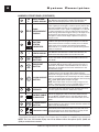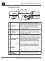
1
Signal Extraction Pulse CO-Oximeter with Rainbow Technology OPERATOR’S MANUAL Signal Extraction Pulse CO-Oximeter OPERATOR’S MANUAL The Radical-7 Pulse CO-Oximeter Operating Instructions provide the necessary information for proper operation of all models of the Radical-7 Pulse CO-Oximetry system. There may be information provided in this manual that is not relevant for your system. General knowledge of pulse oximetry and an understanding of the features and functions of the Radical-7 Pulse CO-Oximeter are prerequisites for its proper use. Do not operate the Radical-7 Pulse CO-Oximeter without completely reading and understanding the instructions in this manual. NOTICE: Purchase or possession of this instrument does not carry any express or implied license to use this instrument with replacement parts which would, alone or in combination with this instrument, fall within the scope of one of the patents relating to this instrument. CAUTION: Federal law (U.S.) restricts this instrument to sale by or on the order of a physician. Masimo Corporation 40 Parker Irvine, CA 92618 USA Tel.: 949-297-7000 Fax.: 949-297-7001 www.masimo.com EU Authorized Representative for Masimo Corporation: EC REP MDSS GmbH Schiffgraben 41 D-30175 Hannover, Germany MEDICAL ELECTRICAL EQUIPMENT WITH RESPECT TO ELECTRIC SHOCK, FIRE AND MECHANICAL HAZARDS ONLY IN ACCORDANCE WITH UL 60601-1/CAN/CSA C22.2 No. 601.1 80fk Covered by one or more of the following U.S. Patents: RE38492, RE38476, 7530955, 7509154, 7499741, 7496393, 7489958, 7471969, 7469157, 7467002, 7377899, 7376453, 7373194, 7355512, 7328053, 7295866, 7254433, 7221971, 7215986, 7467002, 7377899, 7376453, 7373194, 7355512, 7328053, 7295866, 7254433, 7221971, 7215986, 6699194, 6684090, 6658276, 6654624, 6650917, 6643530, 6606511, 6584336, 6515273, 6501975, 6463311, 6430525, 6388240, 6360114, 6263222, 6236872, 6229856, 6157850, 6067462, 6011986, 6002952, 5919134, 5769785, 5758644, 5685299, international equivalents, or one or more of the patents referenced at www.masimo.com/ patents.htm. Products containing SatShare® feature are also covered by U.S. Patent 6,770,028. Other patents pending. © 2010 Masimo Corporation, Masimo, RadNet, Rainbow, SpCO, Discrete Saturation Transform, DST, DCI, FastSat, SatShare, , SET, Signal IQ, SpMet, SpHb, LNOP and LNCS are federally registered trademarks of Masimo Corporation. Radical-7, Patient SafetyNet, Radical Screen, LNOPv, APOD, 3D ALARM, SpOC, Signal Extraction Pulse CO-Oximeter, Pleth Variability Index and PVI are trademarks of Masimo Corporation. Radical-7 Signal Extraction Pulse CO-Oximeter Operator’s Manual i NON-INVASIVE TOTAL HEMOGLOBIN (SpHb) ACCURACY COMPARED TO INVASIVE LABORATORY METHODS* In 492 comparisons of non-invasive total hemoglobin (SpHb) and invasive hemoglobin (tHb) measurements from a laboratory CO-Oximeter, SpHb accuracy was as follows: ■ 0.90 correlation ■ 0.95 g/dL standard deviation ■ Below 12 g/dL, 99% of SpHb readings were < 2 g/dL of the laboratory tHb value ■ At or above 12 g/dL, 94% of SpHb readings were < 2 g/dL of the laboratory value * Masimo FDA Submission Data SAFETY INFORMATION, WARNINGS, CAUTIONS AND NOTES The Radical-7 Signal Extraction Pulse CO-Oximeter is designed to minimize the possibility of hazards from errors in the software program by following sound engineering design processes, Risk Analysis and Software Validation. ii ■ The Radical-7 is to be operated by qualified personnel only. This manual, accessory Directions for Use (DFU), all precautionary information, and specifications should be read before use. ■ Variation in hemoglobin measurements may be profound and may be affected by sample type, body positioning, as well as other physiological conditions. As with most hemoglobin tests, Radical-7 test results should be scrutinized in light of a specific patient’s condition. Any results exhibiting inconsistency with the patient’s clinical status should be repeated and/or supplemented with additional test data. ■ Explosion hazard. Do not use the Radical-7 in the presence of flammable anesthetics or other flammable substance in combination with air, oxygenenriched environments, or nitrous oxide. ■ Electric shock hazard. Do not open the Radical-7 cover except to replace the battery of the Handheld instrument. Only a qualified operator may perform maintenance procedures specifically described in this manual. Refer servicing to Masimo for repair of this equipment. ■ High intensity, extreme lights (including pulsating strobe lights) directed on the sensor may not allow the Radical-7 to obtain readings. ■ The Radical-7 should be considered an early warning instrument. As a trend towards patient hypoxemia is indicated, blood samples should be analyzed by laboratory instruments to completely understand the patient’s condition. ■ If patient hypoxemia is indicated, blood samples should be analyzed by laboratory devices to completely understand the patient's condition. ■ The Radical-7 is NOT intended for use as an apnea monitor. ■ Pulse rate measurement is based on the optical detection of a peripheral flow pulse and therefore may not detect certain arrhythmias. The Radical-7 should not be used as a replacement or substitute for ECG based arrhythmia analysis. ■ As with all medical equipment, carefully route patient cabling to reduce the possibility of patient entanglement or strangulation. ■ Do not place the Radical-7 or accessories in any position that might cause it to fall on the patient. Do not lift the Pulse CO-Oximeter by the power cord or any other cable. Radical-7 Signal Extraction Pulse CO-Oximeter Operator’s Manual SAFETY INFORMATION, WARNINGS, CAUTIONS AND NOTES (CONTINUED) ■ ■ Patient Safety - If a sensor is damaged in any way, discontinue use immediately. Always remove the sensor from the patient and completely disconnect the patient from the Radical-7 before bathing the patient. ■ Interfering Substances: Dyes, or any substance containing dyes, that change usual blood pigmentation may cause erroneous readings. ■ Do not use the Radical-7 or sensors during magnetic resonance imaging (MRI) scanning. Induced current could potentially cause burns. The Radical-7 may affect the MRI image, and the MRI instrument may affect the accuracy of the Radical-7 parameters and measurements. ■ The Radical-7 can be used during defibrillation, but the readings may be inaccurate for up to 20 seconds. ■ If using Radical-7 during full body irradiation, keep the sensor out of the radiation field. If the sensor is exposed to the radiation, the reading might be inaccurate or the instrument might read zero for the duration of the active radiation period. ■ Do not place the Radical-7 where the controls can be changed by the patient. ■ Do not place the Radical-7 on electrical equipment that may affect the Radical-7, preventing it from working properly. ■ Do not expose the Radical-7 to excessive moisture such as direct exposure to rain. Excessive moisture can cause the Radical-7 to perform inaccurately or fail. Do not place containers with liquids on or near the Radical-7. Liquids spilled on the Pulse CO-Oximeter may cause it to perform inaccurately or fail. Changes or modifications not expressly approved by the party responsible for compliance could void the user's authority to operate the equipment. SpO2 is empirically calibrated to functional arterial oxygen saturation in healthy adult volunteers with normal levels of carboxyhemoglobin (COHb) and methemoglobin (MetHb). The Radical-7 can not measure elevated levels of COHb or MetHb. Increases in either COHb or MetHb will affect the accuracy of the SpO2 measurement. Innacurate SpO2 readings can be caused by: ■ ■ ■ ■ ■ Elevated levels of COHb and MetHb ■ For increased COHb: COHb levels above normal tend to increase the level of SpO2. The level of increase is approximately equal to the amount of COHb that is present. NOTE: High levels of COHb may occur with a seemingly normal SpO2. When elevated levels of COHb are suspected, laboratory analysis (CO-Oximetry) of a blood sample should be performed. ■ For increased MetHb: the SpO2 may be decreased by levels of MetHb of up to approximately 10% to 15%. At higher levels of MetHb, the SpO2 may tend to read in the low to mid 80s. When elevated levels of MetHb are suspected, laboratory analysis (CO-Oximetry) of a blood sample should be performed. ■ Intravascular dyes such as indocyanine green or methylene blue. ■ Externally applied coloring (such as nail polish). ■ Elevated levels of Bilirubin Radical-7 Signal Extraction Pulse CO-Oximeter Operator’s Manual iii SAFETY INFORMATION, WARNINGS, CAUTIONS AND NOTES (CONTINUED) ■ ■ ■ Severe anemia ■ Low arterial perfusion ■ Motion artifact Inaccurate SpHb and SpOC readings can be caused by: ■ Intravascular dyes such as indocyanine green or methylene blue ■ Externally applied coloring (such as nail polish) ■ Elevated levels of Bilirubin ■ Low arterial perfusion ■ Motion artifact ■ Low arterial oxygen saturation levels ■ Hemoglobin synthesis disorders ■ Hemoglobinopathy ■ Peripheral vascular disease ■ EMI radiation interference Inaccurate SpCO and SpMet readings can be caused by: ■ Elevated levels of Bilirubin ■ Motion artifact ■ Low arterial oxygen saturation levels ■ Do not place the Radical-7 against a surface. This can cause a system or battery (nonclinical) alarm to be muffled. ■ For home use, ensure that the Radical-7's alarm can be heard from other rooms in the house, especially when noisy appliances such as vacuum cleaners, dishwashers, clothes dryers, televisions, or radios are operating. ■ Additional information specific to Masimo sensors, including information about parameter/ measurement performance during motion and low perfusion, may be found in the sensor's Directions for Use (DFU). ■ If the Radical-7 fails any part of the setup procedures or leakage tests, remove the Radical-7 from operation until qualified service personnel have corrected the situation. Do not incinerate battery. Disposal of product - Comply with local laws in the disposal of the instrument and/or its accessories. To protect against injury from electric shock, follow the directions below: ■ ■ ■ ■ Do not place the instrument near water. Avoid placing the instrument on surfaces with visible liquid spills. ■ Do not soak or immerse the instrument in liquids. ■ Always turn off and disconnect the power cord from the AC power supply before cleaning the instrument. ■ Use cleaning solutions sparingly. This equipment has been tested and found to comply with the limits for medical instruments to the EN 60601-1-2: 2002, Medical Instrument Directive 93/42/EEC. These limits are ■ ■ iv Radical-7 Signal Extraction Pulse CO-Oximeter Operator’s Manual SAFETY INFORMATION, WARNINGS, CAUTIONS AND NOTES (CONTINUED) designed to provide reasonable protection against harmful interference in a typical medical installation. This equipment generates, uses and can radiate radio frequency energy and, if not installed and used in accordance with the instructions, may cause harmful interference to other instruments in the vicinity. However, there is no guarantee that interference will not occur in a particular installation. If this equipment does cause harmful interference to other instruments, which can be determined by turning the equipment off and on, the user is encouraged to try to correct the interference by one or more of the following measures: ■ Reorient or relocate the receiving instrument. ■ Increase the separation between the equipment. ■ Connect the equipment into an outlet on a circuit different from that to which the other instrument(s) are connected. ■ Consult the manufacturer for help. ■ To ensure safety, avoid stacking multiple instruments or placing anything on the instrument during operation. ■ Cleared Use Only: The device and related accessories are cleared by the Food and Drug Administration (FDA) for noninvasive patient monitoring and may not be used for any processes, procedures, experiments or any other use for which the device is not intended or cleared by the FDA, or in any manner inconsistent with the instructions for use or labeling. This device and related accessories are not intended for use in combination with any other medical devices or in high-risk applications. Radical-7 Signal Extraction Pulse CO-Oximeter Operator’s Manual v vi Radical-7 Signal Extraction Pulse CO-Oximeter Operator’s Manual Table of Contents SECTION 1 - OVERVIEW About This Manual . . . . . . . . . . . . . . . . . . . . . . . . . . . . . . . . . . . . . . . . . . . . . . . . . . . . . . 1-1 Warnings, Cautions and Notes. . . . . . . . . . . . . . . . . . . . . . . . . . . . . . . . . . . . . . . . . . . . . 1-2 Product Description . . . . . . . . . . . . . . . . . . . . . . . . . . . . . . . . . . . . . . . . . . . . . . . . . . . . . 1-3 Features . . . . . . . . . . . . . . . . . . . . . . . . . . . . . . . . . . . . . . . . . . . . . . . . . . . . . . . . . . 1-3 Indications For Use . . . . . . . . . . . . . . . . . . . . . . . . . . . . . . . . . . . . . . . . . . . . . . . . . . 1-4 Pulse CO-Oximetry . . . . . . . . . . . . . . . . . . . . . . . . . . . . . . . . . . . . . . . . . . . . . . . . . . . . . 1-4 SpO2 General Description . . . . . . . . . . . . . . . . . . . . . . . . . . . . . . . . . . . . . . . . . . . . 1-4 SpCO General Description . . . . . . . . . . . . . . . . . . . . . . . . . . . . . . . . . . . . . . . . . . . . 1-4 SpMet General Description. . . . . . . . . . . . . . . . . . . . . . . . . . . . . . . . . . . . . . . . . . . . 1-4 SpHb General Description . . . . . . . . . . . . . . . . . . . . . . . . . . . . . . . . . . . . . . . . . . . . . . .1-5 Total Arterial Oxygen Content (CaO2) General Description . . . . . . . . . . . . . . . . . . . .1-5 Principle of Operation . . . . . . . . . . . . . . . . . . . . . . . . . . . . . . . . . . . . . . . . . . . . . . . . 1-5 Functional Saturation . . . . . . . . . . . . . . . . . . . . . . . . . . . . . . . . . . . . . . . . . . . . . . . . 1-6 Radical-7 vs. Drawn Whole Blood Measurements . . . . . . . . . . . . . . . . . . . . . . . . . . 1-6 Signal Extraction Technology (SET) . . . . . . . . . . . . . . . . . . . . . . . . . . . . . . . . . . . . . 1-7 SpCO, SpMet and SpHb Measurements During Patient Motion . . . . . . . . . . . . . . . 1-8 Masimo Rainbow SET Parallel Engines . . . . . . . . . . . . . . . . . . . . . . . . . . . . . . . . . . 1-8 Masimo SET DST ® . . . . . . . . . . . . . . . . . . . . . . . . . . . . . . . . . . . . . . . . . . . . . . . . . . . . . 1-8 SECTION 2 - SYSTEM DESCRIPTION Introduction. . . . . . . . . . . . . . . . . . . . . . . . . . . . . . . . . . . . . . . . . . . . . . . . . . . . . . . . . . . . 2-1 Radical-7 Pulse CO-Oximeter Handheld . . . . . . . . . . . . . . . . . . . . . . . . . . . . . . . . . . . . . 2-2 Handheld Front Panel . . . . . . . . . . . . . . . . . . . . . . . . . . . . . . . . . . . . . . . . . . . . . . . . 2-2 Main Screen Trend Graph Display . . . . . . . . . . . . . . . . . . . . . . . . . . . . . . . . . . . . . . 2-6 Handheld Back Panel . . . . . . . . . . . . . . . . . . . . . . . . . . . . . . . . . . . . . . . . . . . . . . . . 2-7 Radical-7 Pulse CO-Oximeter Standalone. . . . . . . . . . . . . . . . . . . . . . . . . . . . . . . . . . . . 2-8 Standalone Front Panel . . . . . . . . . . . . . . . . . . . . . . . . . . . . . . . . . . . . . . . . . . . . . . 2-9 Standalone Back Panel. . . . . . . . . . . . . . . . . . . . . . . . . . . . . . . . . . . . . . . . . . . . . . 2-10 Symbols . . . . . . . . . . . . . . . . . . . . . . . . . . . . . . . . . . . . . . . . . . . . . . . . . . . . . . . . . 2-11 Radical-7 Monitor Interface . . . . . . . . . . . . . . . . . . . . . . . . . . . . . . . . . . . . . . . . . . . . . . 2-12 SECTION 3 - SETUP Introduction. . . . . . . . . . . . . . . . . . . . . . . . . . . . . . . . . . . . . . . . . . . . . . . . . . . . . . . . . . . . Unpacking and Inspection . . . . . . . . . . . . . . . . . . . . . . . . . . . . . . . . . . . . . . . . . . . . . . . . Preparation for Monitoring . . . . . . . . . . . . . . . . . . . . . . . . . . . . . . . . . . . . . . . . . . . . . . . . Radical-7 Docking Station Power Requirements . . . . . . . . . . . . . . . . . . . . . . . . . . . Initial Battery Charging . . . . . . . . . . . . . . . . . . . . . . . . . . . . . . . . . . . . . . . . . . . . . . . Initial Installation . . . . . . . . . . . . . . . . . . . . . . . . . . . . . . . . . . . . . . . . . . . . . . . . . . . . Monitor Setup . . . . . . . . . . . . . . . . . . . . . . . . . . . . . . . . . . . . . . . . . . . . . . . . . . . . . . . . . . Factory Default Settings . . . . . . . . . . . . . . . . . . . . . . . . . . . . . . . . . . . . . . . . . . . . . . Custom (User) Defined Settings . . . . . . . . . . . . . . . . . . . . . . . . . . . . . . . . . . . . . . . . Adult/Neo Settings (Pre-defined) . . . . . . . . . . . . . . . . . . . . . . . . . . . . . . . . . . . . . . . SatShare Setup . . . . . . . . . . . . . . . . . . . . . . . . . . . . . . . . . . . . . . . . . . . . . . . . . . . . . . . . SatShare Setup. . . . . . . . . . . . . . . . . . . . . . . . . . . . . . . . . . . . . . . . . . . . . . . . . . . . . Philips VueLink Setup. . . . . . . . . . . . . . . . . . . . . . . . . . . . . . . . . . . . . . . . . . . . . . . . . . . . Spacelabs Universal Flexport Setup . . . . . . . . . . . . . . . . . . . . . . . . . . . . . . . . . . . . . . . . Patient SafetyNet/RadNet Setup . . . . . . . . . . . . . . . . . . . . . . . . . . . . . . . . . . . . . . . . . . . Radical-7 Signal Extraction Pulse CO-Oximeter Operator’s Manual 3-1 3-1 3-1 3-1 3-2 3-2 3-3 3-3 3-3 3-4 3-5 3-5 3-7 3-7 3-8 vii vi Table of Contents SECTION 4 - OPERATION Introduction. . . . . . . . . . . . . . . . . . . . . . . . . . . . . . . . . . . . . . . . . . . . . . . . . . . . . . . . . . . . 4-1 Basic Operation . . . . . . . . . . . . . . . . . . . . . . . . . . . . . . . . . . . . . . . . . . . . . . . . . . . . . . . . 4-1 General Setup and Use . . . . . . . . . . . . . . . . . . . . . . . . . . . . . . . . . . . . . . . . . . . . . . 4-1 Successful Monitoring . . . . . . . . . . . . . . . . . . . . . . . . . . . . . . . . . . . . . . . . . . . . . . . . . . . 4-2 Masimo Sensors . . . . . . . . . . . . . . . . . . . . . . . . . . . . . . . . . . . . . . . . . . . . . . . . . . . . 4-3 Numeric Display - SpO2 . . . . . . . . . . . . . . . . . . . . . . . . . . . . . . . . . . . . . . . . . . . . . . 4-4 Sensor Time Remaining . . . . . . . . . . . . . . . . . . . . . . . . . . . . . . . . . . . . . . . . . . . . . . 4-4 Numeric Display - Pulse Rate. . . . . . . . . . . . . . . . . . . . . . . . . . . . . . . . . . . . . . . . . . 4-4 Numeric Display - SpCO. . . . . . . . . . . . . . . . . . . . . . . . . . . . . . . . . . . . . . . . . . . . . . 4-4 Numeric Display - SpMet . . . . . . . . . . . . . . . . . . . . . . . . . . . . . . . . . . . . . . . . . . . . . 4-4 Numeric Display - SpHb . . . . . . . . . . . . . . . . . . . . . . . . . . . . . . . . . . . . . . . . . . . . . . 4-5 Numeric Display - SpOC. . . . . . . . . . . . . . . . . . . . . . . . . . . . . . . . . . . . . . . . . . . . . . 4-5 Numeric Display - (PI). . . . . . . . . . . . . . . . . . . . . . . . . . . . . . . . . . . . . . . . . . . . . . . . 4-5 Pleth Variability Index - (PVI) . . . . . . . . . . . . . . . . . . . . . . . . . . . . . . . . . . . . . . . . . . 4-5 Signal Indication and Quality Indicator (SIQ) . . . . . . . . . . . . . . . . . . . . . . . . . . . . 4-6 Low Perfusion . . . . . . . . . . . . . . . . . . . . . . . . . . . . . . . . . . . . . . . . . . . . . . . . . . . . . . 4-7 Actions To Be Taken . . . . . . . . . . . . . . . . . . . . . . . . . . . . . . . . . . . . . . . . . . . . . . . . . 4-7 Sensitivity . . . . . . . . . . . . . . . . . . . . . . . . . . . . . . . . . . . . . . . . . . . . . . . . . . . . . . . . . 4-8 Touch Key Control Button and Icons . . . . . . . . . . . . . . . . . . . . . . . . . . . . . . . . . . . . . . . . 4-9 Traditional User Interface . . . . . . . . . . . . . . . . . . . . . . . . . . . . . . . . . . . . . . . . . . . . . . . . . 4-9 First Page . . . . . . . . . . . . . . . . . . . . . . . . . . . . . . . . . . . . . . . . . . . . . . . . . . . . . . . . . 4-9 Second Page. . . . . . . . . . . . . . . . . . . . . . . . . . . . . . . . . . . . . . . . . . . . . . . . . . . . . . . 4-9 Simplified User Interface . . . . . . . . . . . . . . . . . . . . . . . . . . . . . . . . . . . . . . . . . . . . . . . . 4-10 First Page . . . . . . . . . . . . . . . . . . . . . . . . . . . . . . . . . . . . . . . . . . . . . . . . . . . . . . . . 4-10 Second Page. . . . . . . . . . . . . . . . . . . . . . . . . . . . . . . . . . . . . . . . . . . . . . . . . . . . . . 4-10 Navigating the Main Menu . . . . . . . . . . . . . . . . . . . . . . . . . . . . . . . . . . . . . . . . . . . . . . . 4-11 Main Menu Selection . . . . . . . . . . . . . . . . . . . . . . . . . . . . . . . . . . . . . . . . . . . . . . . 4-11 Menu Categories. . . . . . . . . . . . . . . . . . . . . . . . . . . . . . . . . . . . . . . . . . . . . . . . . . . 4-11 Editing a Parameter/Measurement . . . . . . . . . . . . . . . . . . . . . . . . . . . . . . . . . . . . . 4-11 Menu Tree . . . . . . . . . . . . . . . . . . . . . . . . . . . . . . . . . . . . . . . . . . . . . . . . . . . . . . . . 4-12 Alarms . . . . . . . . . . . . . . . . . . . . . . . . . . . . . . . . . . . . . . . . . . . . . . . . . . . . . . . . . . . . . . 4-14 Rotate Screen . . . . . . . . . . . . . . . . . . . . . . . . . . . . . . . . . . . . . . . . . . . . . . . . . . . . . . . . 4-18 Display . . . . . . . . . . . . . . . . . . . . . . . . . . . . . . . . . . . . . . . . . . . . . . . . . . . . . . . . . . . . . . 4-18 Clock. . . . . . . . . . . . . . . . . . . . . . . . . . . . . . . . . . . . . . . . . . . . . . . . . . . . . . . . . . . . . . . . 4-20 About . . . . . . . . . . . . . . . . . . . . . . . . . . . . . . . . . . . . . . . . . . . . . . . . . . . . . . . . . . . . . . . 4-20 Config . . . . . . . . . . . . . . . . . . . . . . . . . . . . . . . . . . . . . . . . . . . . . . . . . . . . . . . . . . . . . . . 4-20 General. . . . . . . . . . . . . . . . . . . . . . . . . . . . . . . . . . . . . . . . . . . . . . . . . . . . . . . . . . . . . . 4-21 3D ALARM . . . . . . . . . . . . . . . . . . . . . . . . . . . . . . . . . . . . . . . . . . . . . . . . . . . . . . . . . . . 4-23 Output. . . . . . . . . . . . . . . . . . . . . . . . . . . . . . . . . . . . . . . . . . . . . . . . . . . . . . . . . . . . . . . 4-23 Service . . . . . . . . . . . . . . . . . . . . . . . . . . . . . . . . . . . . . . . . . . . . . . . . . . . . . . . . . . . . . . 4-25 Trend Display . . . . . . . . . . . . . . . . . . . . . . . . . . . . . . . . . . . . . . . . . . . . . . . . . . . . . . . . . 4-26 Trend Auto Scale. . . . . . . . . . . . . . . . . . . . . . . . . . . . . . . . . . . . . . . . . . . . . . . . . . . 4-26 Trend Display Screen . . . . . . . . . . . . . . . . . . . . . . . . . . . . . . . . . . . . . . . . . . . . . . . 4-26 Navigating the Trend Display. . . . . . . . . . . . . . . . . . . . . . . . . . . . . . . . . . . . . . . . . . 4-27 Trend Setup. . . . . . . . . . . . . . . . . . . . . . . . . . . . . . . . . . . . . . . . . . . . . . . . . . . . . . . 4-29 Histogram . . . . . . . . . . . . . . . . . . . . . . . . . . . . . . . . . . . . . . . . . . . . . . . . . . . . . . . . 4-30 Trend Setup and Use . . . . . . . . . . . . . . . . . . . . . . . . . . . . . . . . . . . . . . . . . . . . . . . . . . . 4-31 Introduction . . . . . . . . . . . . . . . . . . . . . . . . . . . . . . . . . . . . . . . . . . . . . . . . . . . . . . . 4-31 viii vii Radical-7 Signal Extraction Pulse CO-Oximeter Operator’s Manual Table of Contents SECTION 4 - OPERATION (CONTINUED) TrendCom Utility Installation . . . . . . . . . . . . . . . . . . . . . . . . . . . . . . . . . . . . . . . . . . TrendCom Utility Operation. . . . . . . . . . . . . . . . . . . . . . . . . . . . . . . . . . . . . . . . . . . Erasing Trend Memory . . . . . . . . . . . . . . . . . . . . . . . . . . . . . . . . . . . . . . . . . . . . . . Trend Data Format . . . . . . . . . . . . . . . . . . . . . . . . . . . . . . . . . . . . . . . . . . . . . . . . . Sample Trend Output . . . . . . . . . . . . . . . . . . . . . . . . . . . . . . . . . . . . . . . . . . . . . . . Backlight Operation . . . . . . . . . . . . . . . . . . . . . . . . . . . . . . . . . . . . . . . . . . . . . . . . . . . . SatShare Operation . . . . . . . . . . . . . . . . . . . . . . . . . . . . . . . . . . . . . . . . . . . . . . . . . . . . Home Mode Operation . . . . . . . . . . . . . . . . . . . . . . . . . . . . . . . . . . . . . . . . . . . . . . . . . . Password Operation . . . . . . . . . . . . . . . . . . . . . . . . . . . . . . . . . . . . . . . . . . . . . . . . . . . . 4-31 4-31 4-32 4-32 4-32 4-33 4-33 4-36 4-36 SECTION 5 - ALARMS AND MESSAGES Alarm Identification. . . . . . . . . . . . . . . . . . . . . . . . . . . . . . . . . . . . . . . . . . . . . . . . . . . . . . System Messages . . . . . . . . . . . . . . . . . . . . . . . . . . . . . . . . . . . . . . . . . . . . . . . . . . . . . . 3D ALARM Overview . . . . . . . . . . . . . . . . . . . . . . . . . . . . . . . . . . . . . . . . . . . . . . . . . . . . Desat Index Alarm . . . . . . . . . . . . . . . . . . . . . . . . . . . . . . . . . . . . . . . . . . . . . . . . . . Perfusion Index (PI) Delta Alarm . . . . . . . . . . . . . . . . . . . . . . . . . . . . . . . . . . . . . . . Desat Index Alarm . . . . . . . . . . . . . . . . . . . . . . . . . . . . . . . . . . . . . . . . . . . . . . . . . . . . . . User Interaction to Implement Desat Index Alarm . . . . . . . . . . . . . . . . . . . . . . . . . . Perfusion Index (PI) Delta Alarm . . . . . . . . . . . . . . . . . . . . . . . . . . . . . . . . . . . . . . . . . . . User Interaction to Implement PI Delta Alarm . . . . . . . . . . . . . . . . . . . . . . . . . . . . . . . . . 3D ALARM Menu . . . . . . . . . . . . . . . . . . . . . . . . . . . . . . . . . . . . . . . . . . . . . . . . . . . . . . . 5-1 5-2 5-5 5-5 5-5 5-6 5-7 5-8 5-8 5-8 SECTION 6 - TROUBLESHOOTING Troubleshooting . . . . . . . . . . . . . . . . . . . . . . . . . . . . . . . . . . . . . . . . . . . . . . . . . . . . . . . . 6-1 SECTION 7 - SPECIFICATIONS Radical-7 Specifications . . . . . . . . . . . . . . . . . . . . . . . . . . . . . . . . . . . . . . . . . . . . . . . . . . Performance . . . . . . . . . . . . . . . . . . . . . . . . . . . . . . . . . . . . . . . . . . . . . . . . . . . . . . . Accuracy . . . . . . . . . . . . . . . . . . . . . . . . . . . . . . . . . . . . . . . . . . . . . . . . . . . . . . . . . . Electrical . . . . . . . . . . . . . . . . . . . . . . . . . . . . . . . . . . . . . . . . . . . . . . . . . . . . . . . . . . Environmental . . . . . . . . . . . . . . . . . . . . . . . . . . . . . . . . . . . . . . . . . . . . . . . . . . . . . . Physical Characteristics . . . . . . . . . . . . . . . . . . . . . . . . . . . . . . . . . . . . . . . . . . . . . . Serial Interface Specifications . . . . . . . . . . . . . . . . . . . . . . . . . . . . . . . . . . . . . . . . . . . . . Serial Interface Setup . . . . . . . . . . . . . . . . . . . . . . . . . . . . . . . . . . . . . . . . . . . . . . . . Serial Printer Setup. . . . . . . . . . . . . . . . . . . . . . . . . . . . . . . . . . . . . . . . . . . . . . . . . . Analog Output/Nurse Call Specifications . . . . . . . . . . . . . . . . . . . . . . . . . . . . . . . . . . . . . Analog Output . . . . . . . . . . . . . . . . . . . . . . . . . . . . . . . . . . . . . . . . . . . . . . . . . . . . . . Calibration. . . . . . . . . . . . . . . . . . . . . . . . . . . . . . . . . . . . . . . . . . . . . . . . . . . . . . . . . Nurse Call . . . . . . . . . . . . . . . . . . . . . . . . . . . . . . . . . . . . . . . . . . . . . . . . . . . . . . . . . 7-1 7-1 7-1 7-2 7-2 7-2 7-4 7-4 7-5 7-5 7-6 7-6 7-6 SECTION 8 - SENSORS & PATIENT CABLES Introduction. . . . . . . . . . . . . . . . . . . . . . . . . . . . . . . . . . . . . . . . . . . . . . . . . . . . . . . . . . . . Selecting a Masimo SET Sensor . . . . . . . . . . . . . . . . . . . . . . . . . . . . . . . . . . . . . . . Sensor Application Instructions . . . . . . . . . . . . . . . . . . . . . . . . . . . . . . . . . . . . . . . . Masimo Rainbow Sensors . . . . . . . . . . . . . . . . . . . . . . . . . . . . . . . . . . . . . . . . . . . . . . . . Rainbow Adhesive Sensors . . . . . . . . . . . . . . . . . . . . . . . . . . . . . . . . . . . . . . . . . . . Rainbow ReSposable™ Pulse CO-Oximeter Sensor System . . . . . . . . . . . . . . . . . Rainbow Reusable Sensors . . . . . . . . . . . . . . . . . . . . . . . . . . . . . . . . . . . . . . . . . . . Rainbow Direct Connect Sensors. . . . . . . . . . . . . . . . . . . . . . . . . . . . . . . . . . . . . . . 8-1 8-1 8-1 8-2 8-2 8-2 8-2 8-2 Radical-7 Signal Extraction Pulse CO-Oximeter Operator’s Manual ix viii Table of Contents SECTION 8 - SENSORS & PATIENT CABLES (CONTINUED) Masimo SpO2 Sensors. . . . . . . . . . . . . . . . . . . . . . . . . . . . . . . . . . . . . . . . . . . . . . . . . . . 8-3 ReSposable Pulse CO-Oximeter Sensor System . . . . . . . . . . . . . . . . . . . . . . . . . . 8-3 Red Direct Connect Sensors . . . . . . . . . . . . . . . . . . . . . . . . . . . . . . . . . . . . . . . . . . 8-3 ® LNOP Reusable Sensors . . . . . . . . . . . . . . . . . . . . . . . . . . . . . . . . . . . . . . . . . . . . 8-3 ® LNOP Adhesive Sensors. . . . . . . . . . . . . . . . . . . . . . . . . . . . . . . . . . . . . . . . . . . . . 8-3 TM LNOPv Adhesive Sensors . . . . . . . . . . . . . . . . . . . . . . . . . . . . . . . . . . . . . . . . . . . . . . . . 8-3 ® LNOP Specialty Sensors. . . . . . . . . . . . . . . . . . . . . . . . . . . . . . . . . . . . . . . . . . . . . 8-4 ® M-LNCS™/LNCS Reusable Sensors . . . . . . . . . . . . . . . . . . . . . . . . . . . . . . . . . . . 8-4 ® M-LNCS™/LNCS Adhesive Sensors . . . . . . . . . . . . . . . . . . . . . . . . . . . . . . . . . . . 8-4 ® M-LNCS™/LNCS Specialty Sensors . . . . . . . . . . . . . . . . . . . . . . . . . . . . . . . . . . . 8-4 Sensor Accuracy. . . . . . . . . . . . . . . . . . . . . . . . . . . . . . . . . . . . . . . . . . . . . . . . . . . . 8-4 Cleaning And Reuse Of Masimo Reusable Sensors and Cables. . . . . . . . . . . . . . . 8-4 Reattachment of Single Use Adhesive Sensors. . . . . . . . . . . . . . . . . . . . . . . . . . . . 8-5 SECTION 9 - SERVICE AND MAINTENANCE Introduction. . . . . . . . . . . . . . . . . . . . . . . . . . . . . . . . . . . . . . . . . . . . . . . . . . . . . . . . . . . . Cleaning . . . . . . . . . . . . . . . . . . . . . . . . . . . . . . . . . . . . . . . . . . . . . . . . . . . . . . . . . . . . . . Battery Operation and Maintenance . . . . . . . . . . . . . . . . . . . . . . . . . . . . . . . . . . . . . . . . Replacing the Batteries. . . . . . . . . . . . . . . . . . . . . . . . . . . . . . . . . . . . . . . . . . . . . . . Replacing the Fuses . . . . . . . . . . . . . . . . . . . . . . . . . . . . . . . . . . . . . . . . . . . . . . . . . Performance Verification. . . . . . . . . . . . . . . . . . . . . . . . . . . . . . . . . . . . . . . . . . . . . . . . . . Service and Repair. . . . . . . . . . . . . . . . . . . . . . . . . . . . . . . . . . . . . . . . . . . . . . . . . . . . . . Repair Policy . . . . . . . . . . . . . . . . . . . . . . . . . . . . . . . . . . . . . . . . . . . . . . . . . . . . . . . Return Procedure . . . . . . . . . . . . . . . . . . . . . . . . . . . . . . . . . . . . . . . . . . . . . . . . . . . Warranty. . . . . . . . . . . . . . . . . . . . . . . . . . . . . . . . . . . . . . . . . . . . . . . . . . . . . . . . . . . . . . Exclusions . . . . . . . . . . . . . . . . . . . . . . . . . . . . . . . . . . . . . . . . . . . . . . . . . . . . . . . . . . . . Sales & End-User License Agreement . . . . . . . . . . . . . . . . . . . . . . . . . . . . . . . . . . . . . . Restrictions . . . . . . . . . . . . . . . . . . . . . . . . . . . . . . . . . . . . . . . . . . . . . . . . . . . . . . . . . . . 9-1 9-1 9-2 9-4 9-4 9-5 9-7 9-7 9-7 9-8 9-8 9-9 9-9 SECTION 10 - ACCESSORIES Accessories . . . . . . . . . . . . . . . . . . . . . . . . . . . . . . . . . . . . . . . . . . . . . . . . . . . . . . . . . . 10-1 x ix Radical-7 Signal Extraction Pulse CO-Oximeter Operator’s Manual Overview 1 About This Manual This manual explains how to set up and use the Radical-7™ Pulse CO-Oximeter containing Masimo Rainbow® SET® technology. Important safety information relating to general use of the Pulse CO-Oximeter appears before this introduction. Other important safety information is located throughout the manual where appropriate. Read the entire safety information section before you operate the monitor. In addition to the safety section, this manual includes the following sections: SECTION 1 OVERVIEW gives a general description of Radical-7 Pulse CO-Oximeter. SECTION 2 SYSTEM DESCRIPTION describes the Radical-7 Pulse CO-Oximeter system and its functions and features. SECTION 3 SETUP describes how to setup the Radical-7 Pulse CO-Oximeter for use. SECTION 4 OPERATION describes the operation of the Radical-7 Pulse CO-Oximetry system. SECTION 5 ALARMS AND MESSAGES describes the alarm system messages. SECTION 6 TROUBLESHOOTING describes troubleshooting information. SECTION 7 SPECIFICATIONS gives the detailed specifications of the Radical-7 Pulse CO-Oximeter. SECTION 8 SENSORS & PATIENT CABLES outlines how to use and care for Masimo Rainbow SET technology sensors, Masimo Rainbow SET technology patient cables, Masimo Red sensors and Masimo Red patient cables. SECTION 9 SERVICE AND MAINTENANCE describes how to maintain, service and obtain repair for the Radical-7 Pulse CO-Oximeter. SECTION 10 ACCESSORIES lists the available Radical-7 Pulse CO-Oximeter accessories. Radical-7 Signal Extraction Pulse CO-Oximeter Operator’s Manual 1-1 1 Overview Warnings, Cautions and Notes Please read and follow any warnings, cautions and notes presented throughout this manual. An explanation of these labels are as follows: A WARNING is provided when actions may result in a serious outcome (i.e., injury, serious adverse affect, death) to the patient or user. Look for text in a gray shaded box. Sample of Warning: WARNING: THIS IS A SAMPLE OF A WARNING STATEMENT. A CAUTION is given when any special care is to be exercised by the patient or user to avoid injury to the patient, damage to this instrument or damage to other property. Sample of Caution: CAUTION: THIS IS A SAMPLE OF A CAUTION STATEMENT. A NOTE is provided when extra general information is applicable. Sample of Note: NOTE: This is a sample of a Note. 1-2 Radical-7 Signal Extraction Pulse CO-Oximeter Operator’s Manual Overview 1 Product Description The Radical-7 Pulse CO-Oximeter is a noninvasive, arterial oxygen saturation, total hemoglobin concentration and pulse rate monitor. The Radical-7 Pulse CO-Oximeter can be used as either a Handheld or a Standalone monitor. The Radical-7 Pulse CO-Oximeter features a backlit Liquid Crystal Display (LCD) that continuously displays numeric values for SpO2, SpMet®, SpCO®*, SpHb®, SpOC™*, pulse rate, Perfusion Index (PI) and Pleth Variability Index (PVI). It also provides graphical displays for plethysmographic waveform, Signal Identification and Quality Indicator (Signal IQ®). The Radical-7 Pulse CO-Oximeter can be used to interface with a multiparameter patient monitor to provide Masimo SET SpO2 and pulse rate information to that monitor for display. FEATURES These features are common to the Radical-7 family: ■ Masimo SET is clinically proven to be the highest sensitivity and specificity pulse oximeter technology in the world. ■ Rainbow technology uses 7+ wavelengths of light to continuously and noninvasively measure carboxyhemoglobin (SpCO®*), methemoglobin (SpMet™*) and total hemoglobin (SpHb™*), as well as providing a more reliable probe-off detection. ■ Total Oxygen Content (SpOC™*) provides a calculated measurement of the amount of oxygen in arterial blood, which may provide useful information about oxygen both dissolved in plasma and combined with hemoglobin. ■ Perfusion Index (PI) with trending capability indicates arterial pulse signal strength and may be used as a diagnostic tool during low perfusion. ■ *Pleth Variability Index (PVI) may show changes that reflect physiologic factors such as vascular tone, circulating blood volume, and intrathoracic pressure excursions.1 ■ Accurate on cyanotic infants with congenital heart disease when used with an LNOP® Blue Sensor. ■ Signal IQ® waveform for signal identification and quality indication during excessive motion and low signal to noise situations. ■ FastSat® tracks rapid changes in arterial O2 with high fidelity unlike any other pulse oximeter. ■ Variable pitch provides tonal variance for every 1% change in saturation. ■ SatShare® interface allows transfer of SpO2 and pulse rate to an existing multiparameter monitor and allows for the reading of SpCO, SpMet, SpHb and SpOC on the Radical-7 monitor. ■ Automatic screen rotation provides upright display for vertical or horizontal monitor positioning. ■ Remote alarming interface. ■ Trend Auto Scale feature. ■ Detachable portable handheld for patient transport. ■ *3D ALARM™ ■ Desat Index Alarm™ enables clinicians to detect an increasing quantity of smaller desaturations that may precede declining respiratory status. ■ PI Delta Alarm™ alerts clinicians to possible changes in perfusion, often a reliable indicator of illness severity. 1 The utility of PVI is unknown at this time and requires further clinical studies. Technical factors that may affect PVI include probe malposition and patient motion. * Optional parameters/measurements Radical-7 Signal Extraction Pulse CO-Oximeter Operator’s Manual 1-3 1 Overview INDICATIONS FOR USE The Radical-7 Pulse CO-Oximeter and accessories are indicated for the continuous, non-invasive monitoring of functional oxygen saturation of arterial hemoglobin (SpO2), pulse rate (measured by a SpO2 sensor), carboxyhemoglobin and methemoglobin concentrations expressed in percentage (SpCO and SpMet) and total hemoglobin concentration expressed in grams per deciliter (SpHb). The Radical-7 Pulse CO-Oximeter and accessories are indicated for use with adult, pediatric and neonatal patients during both motion and no motion conditions, who are well or poorly perfused patients in hospitals, hospital-type facilities, mobile and home environments. Pulse CO-Oximetry SpO2 GENERAL DESCRIPTION Pulse CO-Oximetry is a continuous and noninvasive method of measuring the level of arterial oxygen saturation in blood. The measurement is taken by placing a sensor on a patient, usually on the fingertip for adults and the hand or foot for neonates. The sensor is connected to the Pulse CO-Oximetry instrument with a patient cable. The sensor collects signal data from the patient and sends it to the instrument. The instrument displays the calculated data in three ways: 1. As a percent value for arterial oxygen saturation (SpO2) 2. As a pulse rate (PR) 3. As a plethysmographic waveform The following figure shows the general monitoring setup. SpCO GENERAL DESCRIPTION 6 20 10.0 --13 ----- 17 7 SpHb g/dl 3.00 --- 1. Instrument SpOC ml/dl 2. Patient Cable 3. Sensor Pulse CO-Oximetry is a continuous and noninvasive method of measuring the levels of carbon monoxide concentration (SpCO) in arterial blood. It relies on the same basic principles of pulse oximetry (spectrophotometry) to make its SpCO measurement. The measurement is obtained by placing a sensor on a patient, usually on the fingertip for adults and the hand or foot for infants. The sensor connects either directly to the Pulse CO-Oximetry instrument or through a patient cable. The sensor collects signal data from the patient and sends it to the instrument. The instrument displays the calculated data as percentage value for the SpCO, which reflect blood levels of carbon monoxide bound to hemoglobin. SpMet GENERAL DESCRIPTION Pulse CO-Oximetry is a continuous and noninvasive method of measuring the levels of methemoglobin concentration (SpMet) in arterial blood. It relies on the same basic principles of pulse oximetry (spectrophotometry) to make its SpMet measurement. The measurement is obtained by placing a sensor on a patient, usually on the fingertip for adults and the hand or foot for infants. The sensor connects either directly to the Pulse CO-Oximetry instrument or 1-4 Radical-7 Signal Extraction Pulse CO-Oximeter Operator’s Manual 1 Overview through a patient cable. The sensor collects signal data from the patient and sends it to the instrument. The instrument displays the calculated data as percentage value for the SpMet. SpHb GENERAL DESCRIPTION Pulse CO-Oximetery is a continuous and non-invasive method of measuring the levels of total hemoglobin (SpHb) in arterial blood. It relies on the same principles of pulse oximetry to make the SpHb measurement. The measurement is taken by a sensor capable of measuring SpHb, usually on the fingertip for adult and pediatric patients. The sensor connects directly to the Pulse CO-Oximeter or with a patient cable. The sensor collects signal data from the patient and sends it to the instrument. The instrument displays the calculated data as measurement of total hemoglobin concentration. TOTAL ARTERIAL OXYGEN CONTENT (CaO2) GENERAL DESCRIPTION 2 Oxygen (O2) is carried in the blood in two forms, either dissolved in plasma or combined with hemoglobin. The amount of oxygen in the arterial blood is termed the oxygen content (CaO2) and is measured in units of ml O2/dl blood. One gram of hemoglobin (Hb) can carry 1.34 ml of oxygen, whereas 100 ml of blood plasma may carry approximately 0.3 ml of oxygen. The oxygen content is determined mathematically as: CaO2 = 1.34 (ml O2/g Hb) x Hb (g/dl) x HbO2 + PaO2 (mm Hg) x (0.3 ml O2/ 100 mm Hg/dl) Where HbO2 is the fractional arterial oxygen saturation and PaO2 is the partial pressure of arterial oxygen. For typical PaO2 values, the second part of the above equation [PaO2 (mm Hg) x (0.3 ml O2/ 100 mm Hg/dl] is approximately 0.3 ml/dl. Furthermore, for typical carboxyhemoglobin and methemoglobin levels, the functional saturation (SpO2) as measured by a pulse oximeter is given by: SpO2 = 1.02 x HbO2 2 Martin, Laurence. All You Really Need to Know to Interpret Arterial Blood Gases, Second Edition. New York: Lippincott Williams & Wilkins, 1999. SpOC General Description (Pulse CO-Oximetry) The above approximations result in the following reduced equation for oxygen content via the Pulse CO-Oximeter: SpOC (ml/dl*) = 1.31 (ml O2/g Hb) x SpHb (g/dl) x SpO2 + 0.3 ml/dl * When ml O2/g Hb is multiplied by g/dl of SpHb, the gram unit in the denominator of ml/g cancels the gram unit in the numerator of g/dl resulting in ml/dl (ml of oxygen in one dl of blood) as the unit of measure for SpOC. PRINCIPLE OF OPERATION 1. Oxyhemoglobin (oxygenated blood), deoxyhemoglobin (non-oxygenated blood), carboxyhemoglobin (blood with carbon monoxide content), methemoglobin (blood with oxidized hemoglobin) and blood plasma constituents differ in their absorption of visible and infrared light (using spectrophotometry). 2. The amount of arterial blood in tissue changes with your pulse (photoplethysmography). Therefore, the amount of light absorbed by the varying quantities of arterial blood changes as well. The Radical-7 Pulse CO-Oximeter uses a multi-wavelength sensor to distinguish between oxygenated blood, deoxygenated blood, blood with carbon monoxide, oxidized blood and blood plasma. The Radical-7 utilizes a sensor with various light-emitting diodes (LEDs) that pass Radical-7 Signal Extraction Pulse CO-Oximeter Operator’s Manual 1-5 1 1 Overview light through the site to a diode (detector). Signal data is obtained by passing various visible and infrared lights (LEDs, 500 to 1400nm) through a capillary bed (for example, a fingertip, a hand, a foot) and measuring changes in light absorption during the blood pulsatile cycle. This information may be useful to clinicians. The maximum radiant power of the strongest light is rated at ≤ 25 mW. The detector receives the light, converts it into an electronic signal and sends it to the Radical-7 for calculation. Absorption Spectra 4.0 Carboxyhemoglobin 3.5 Oxyhemoglobin Methemoglobin Deoxyhemoglobin Absorption (1/mm) 3.0 Plasma 2.5 2.0 1.5 1.0 0.5 0 600 800 1000 1200 1400 1600 Wavelength (nm) Once the Radical-7 receives the signal from the sensor, it utilizes Masimo Rainbow SET signal extraction technology to calculate the patient’s functional oxygen saturation (SpO2 (%)), blood levels of carboxyhemoglobin (SpCO (%)), methemoglobin (SpMet (%)), Total Hemoglobin concentration (SpHb (g/dl)) and pulse rate (PR (BPM)). The SpCO, SpMet and SpHb measurements rely on a multiwavelength calibration equation to quantify the percentage of carbon monoxide and methemoglobin and the concentration of total hemoglobin in arterial blood. In an ambient temperature of 35º C the maximum skin surface temperature has been measured at less than 106º F (41º C), verified by Masimo sensor skin temperature test procedure. FUNCTIONAL SATURATION The Radical-7 is calibrated to measure and display functional saturation (SpO2): the amount of oxyhemoglobin expressed as a percentage of the hemoglobin that is available to transport oxygen. Note that carboxyhemoglobin is not capable of transporting oxygen, but is recognized as oxygenated hemoglobin by conventional pulse oximetry. 1 2 1. 2. Light Emitting Diodes (LEDs) (7 + wavelengths) Detector RADICAL-7 vs. DRAWN WHOLE BLOOD MEASUREMENTS When SpO2, SpCO, SpMet and SpHb measurements obtained from the Radical-7 (noninvasive) are compared to drawn whole blood (invasive) measurements by blood gas and/or laboratory CO-Oximetry methods, caution should be taken when evaluating and interpreting the results. The blood gas and/or laboratory CO-Oximetry measurements may differ from the SpO2, SpCO, SpMet, SpHb and SpOC measurements of the Radical-7 Pulse CO-Oximeter. In the case of SpO2, different results are usually obtained from the arterial blood gas sample if the calculated measurement is not appropriately corrected for the effects of variables that shift the relationship between the partial pressure of oxygen (PO2) and saturation, such as: pH, 1-6 Radical-7 Signal Extraction Pulse CO-Oximeter Operator’s Manual Overview 1 temperature, the partial pressure of carbon dioxide (PCO2), 2,3-DPG, and fetal hemoglobin. In the case of SpCO, different results are also expected if concentration of methemoglobin in the blood gas sample is abnormal (greater than 2% for methemoglobin concentration). High levels of bilirubin may cause erroneous SpO2, SpMet, SpCO and SpHb readings. As blood samples are usually taken over a period of 20 seconds (the time it takes to draw the blood) a meaningful comparison can only be achieved if the oxygen saturation, carboxyhemoglobin and methemoglobin concentration of the patient are stable and not changing over the period of time that the blood gas sample is taken. Subsequently, blood gas and laboratory CO-Oximetry measurements of SpO2, SpCO, SpMet, SpHb and SpOC may vary with the rapid administration of fluids and in procedures such as dialysis. Additionally, drawn, wholeblood testing can be affected by sample handling methods and time elapsed between blood draw and sample testing. SIGNAL EXTRACTION TECHNOLOGY (SET) Masimo Signal Extraction Technology's signal processing differs from that of conventional pulse oximeters. Conventional pulse oximeters assume that arterial blood is the only blood moving (pulsating) in the measurement site. During patient motion, however, the venous blood also moves, causing conventional pulse oximeters to read low values, because they cannot distinguish between the arterial and venous blood movement (sometimes referred to as noise). Masimo SET pulse oximetry utilizes parallel engines and adaptive digital filtering. Adaptive filters are powerful because they are able to adapt to the varying physiologic signals and/or noise and separate them by looking at the whole signal and breaking it down to its fundamental components. The Masimo SET signal processing algorithm, Discrete Saturation Transform® (DST®), in parallel with Fast Saturation Transform® (FST®), reliably identifies the noise, isolates it and, using adaptive filters, cancels it. It then reports the true arterial oxygen saturation for display on the monitor. Radical-7 Signal Extraction Pulse CO-Oximeter Operator’s Manual 1-7 1 Overview SpCO, SpMet AND SpHb MEASUREMENTS DURING PATIENT MOTION The Radical-7 displays measurements of SpCO, SpMet and SpHb during patient motion. However, because of the changes in the physiological parameters such as blood volume, arterial-venous coupling, etc. that occur during patient motion, the accuracy of such measurements may not be reliable during excessive motion. The measurements for SpCO, SpMet and SpHb display “---” and a message, “LOW SpCO SIQ”, “LOW SpMet SIQ” or “LOW SpHb SIQ”, displays to alert the clinician that the instrument does not have confidence in the value due to poor signal quality caused by excessive motion or other signal interference. MASIMO RAINBOW SET PARALLEL ENGINES This figure is for conceptual purposes only. 12 FST MST SpOC MASIMO SET DST ® 1-8 Radical-7 Signal Extraction Pulse CO-Oximeter Operator’s Manual System Description 2 Introduction The Radical-7 provides the functionality of three instruments in one: ■ The Radical-7 is a fully featured Handheld Pulse CO-Oximeter. ■ The Radical-7 is a fully featured Standalone Pulse CO-Oximeter. ■ The Radical-7 interfaces to the SpO2 input module of multiparameter patient monitors* to upgrade conventional pulse oximetry technology to Masimo SET technology. The Handheld portion of the Radical-7 contains the majority of the Pulse CO-Oximeter features. All pulse cooximetry measurement information, as well as instrument status data is displayed on the Handheld LCD screen. All user input is performed through the control buttons on the front panel. The sensor cable connector is located on the Radical-7 Handheld Pulse CO-Oximeter. 16 7 10.1 13 SpOC The Handheld Pulse CO-Oximeter snaps into the Radical Docking Station to provide a fully featured standalone Pulse CO-Oximeter. The Docking Station connects to AC power for standalone operation or charging of the Handheld. An optional Docking Station battery is available. The standalone Radical-7 features nurse call, analog output and interfaces to serial printers. Utilizing a SatShare® cable, the standalone 76 97 10.0 SpHb g/dl SpOC 17 7 Radical-7 also interfaces with the SpO2 input of a validated multiparameter patient monitor*, instantly upgrading the conventional pulse co-oximetry to Masimo SET pulse oximetry. The SatShare cable attaches to the back of the Radical Docking Station, and SatShare cables are available to interface with most multiparameter patient monitors*. CAUTION: ■ THE WAVEFORM DISPLAYED ON THE MULTIPARAMETER PATIENT MONITOR IS A SIMULATED SIGNAL (NON-NORMALIZED). REFER TO THE RADICAL-7 PULSE CO-OXIMETER DISPLAY FOR PATIENT WAVEFORM. ■ IF DISPLAYING THE SIMULATED WAVEFORM IS NOT DESIRABLE, IT IS RECOMMENDED TO TURN OFF THE PLETHYSMOGRAPHIC WAVEFORM DISPLAY ON THE MULTIPARAMETER MONITOR. ■ ONLY USE A SATSHARE CABLE THAT HAS A FERRITE BEAD INSTALLED. ■ ONLY SpO2 AND PULSE RATE CAN BE DISPLAYED ON THE MULTIPARAMETER MONITOR WITH SATSHARE. Refer to Section 3, SatShare Setup and Section 4, SatShare Operation for additional details. *Contact Masimo for the latest list of SatShare validated multiparameter monitors. Radical-7 Signal Extraction Pulse CO-Oximeter Operator’s Manual 2-1 2 System Description Radical-7 Pulse CO-Oximeter Handheld The Handheld Radical-7 Pulse CO-Oximeter provides most of the functionality of the Pulse CO-Oximeter. All user input and displays are controlled by this part of the Radical-7 Pulse CO-Oximeter system. The patient cable connects into the connector on the Handheld instrument. The Handheld is battery powered and can be used either as a transport monitor or as a Handheld Pulse CO-Oximeter for spot checks. HANDHELD FRONT PANEL The following figure and corresponding text outline all the features of the Handheld Radical-7 Pulse CO-Oximeter: Pleth + Signal IQ View 10.0 17 7 SpHb g/dl ----- ----- 13 SpOC ml/dl 32 30 29 28 Numbers View 32 30 28 ----- 10.0 SpHb g/dl 2-2 17 7 13 ----- SpOC ml/dl Radical-7 Signal Extraction Pulse CO-Oximeter Operator’s Manual System Description 2 HANDHELD FRONT PANEL (CONTINUED) 1 HANDHELD RELEASE BUTTON 2 97 The functional arterial hemoglobin oxygen saturation is displayed in units of percentage SpO2. The upper and lower SpO2 alarm limits are also displayed next to the SpO2 measurement. When a sensor is not connected to a patient and SpO2 during pulse search, the display will show dashed lines and MEASUREMENT the message "Sensor Off" will appear at the top of the display DISPLAY screen. When the measured value is outside of the alarm limits, the SpO2 measurement display flashes and an alarm will sound. The oxygen saturation is calculated and the display is updated at a frequency of once per second. 3 Masimo Rainbow SET MASIMO SET OR MASIMO RAINBOW SET 4 99 85 SATURATION ALARM LIMITS DISPLAY 5 Press down the Handheld Release Button and pull the Handheld instrument off the Docking Station. The Masimo SET or Masimo rainbow SET label is shown on the Radical-7 display when either SET processing is active. NOTE: Patient information, not SET activity, will be displayed when using a RadNet® compatible instrument connected to a monitoring system. The Saturation Alarm Limits Display shows the upper and lower saturation alarm limits. When an alarm limit is exceeded, the SpO2 value and the violated limit flashes. The alarm status indicator (a bell) can be shown with or without a slash. It flashes when an alarm condition is present. When the alarm is silenced using the Alarm Silence Button, an alarm status ALARM STATUS indicator with a slash and a timer is shown to indicate that the alarm is temporarily silenced. When the alarm is silenced through the All INDICATOR Mute menu selection (which is permanent until power is cycled or deselected using the menu), or when the Interface Alarm SpO2/BPM is set to "No", an alarm status indicator with a slash is shown to indicate the alarm has been silenced. The measurement of methemoglobin concentration levels is displayed in units of percentage SpMet. The upper and lower SpMet alarm limits are also displayed next to the SpMet SpMet* measurement. When a sensor is not connected to a patient and MEASUREMENT during pulse search, the display will show dashed lines and DISPLAY the message "Sensor Off" will appear at the top of the display screen. The methemoglobin is calculated and the display is updated at a frequency of once per second. SpMet ALARM The SpMet Alarm Limits Display shows the upper and lower alarm limits. When the measured value is outside of the alarm limits, the LIMITS DISPLAY SpMet measurement display flashes and an alarm will sound. 6 1.6 7 3.0 0.3 8 Sensor Off The system messages generated by the instrument are displayed SYSTEM MESSAGE AREA in the System Message Area. See Section 5, System Messages. 9 Philips VueLink SERIAL OUTPUT with the Docking Station is connected to an external instrument via the serial port. During SatShare, the Output Mode will display MODE The Serial Output Mode displays the selected output interface 10 20 the type of SatShare cable. The measurement of carbon monoxide concentration levels is displayed in units of percentage SpCO. When a sensor is not SpCO* connected to a patient and during pulse search, the display will show MEASUREMENT dashed lines and the message Sensor Off will appear at the top of the DISPLAY display screen. The carboxyhemoglobin is calculated and the display is updated at a frequency of once per second. * For instruments that include SpMet, SpCO and SpHb parameters: the SpMet, SpCO, SpHb and SpOC parameters/measurements will be dimly lit in the display screen if a patient cable is not attached or a non-Rainbow sensor is being used. NOTE: The Pulse CO-Oximeter display view will be different without the optional SpCO, SpMet and SpHb parameters/measurements. Radical-7 Signal Extraction Pulse CO-Oximeter Operator’s Manual 2-3 2 System Description HANDHELD FRONT PANEL (CONTINUED) 50 5 11 12 10.0 The SpCO Alarm Limits Display shows the upper and lower alarm SpCO ALARM limits. When the measured value is outside of the alarm limits, the LIMITS DISPLAY SpCO measurement display flashes and an alarm will sound. SpHb ALARM LIMITS DISPLAY The measurement of total hemoglobin concentration levels is displayed in units of grams per deciliter (g/dL) or milimoles per liter (mmol/L). The upper and lower SpHb alarm limits are also displayed next to the SpHb measurement. When a sensor capable of reading SpHb is not connected to a patient and during pulse search, the display will show dashed lines and the message “Sensor Off” will appear at the top of the display screen. The display will show dashed lines during pulse search. The total hemoglobin is calculated and the display is updated at a frequency of once per second. The Battery Status Indicators show the capacity of the Radical-7 Handheld and optional Docking Station batteries. The indicator flashes when less than 15 minutes of battery life is left and the battery needs to be recharged. The Docking Station Battery Status indicator is not shown when the optional Docking Station battery is not present. The SpHb Alarm Limits Display shows the upper and lower alarm limits. When the measured value is outside of the alarm limits, the SpHb measurement display flashes and an alarm will sound. TOUCH KEY CONTROL BUTTONS Press a Touch Key Control Button to select the corresponding touch key icon. See Section 4, Touch Key Control Buttons and Icons for more details. SpHb* MEASUREMENT DISPLAY BATTERY STATUS INDICATORS 13 17 7 14 15 Press the Backlight Button to change the illumination level of the backlight. With the AC line power connected, five levels of illumination are available. In the Handheld mode, four levels of illumination are available. Use the lowest illumination for most efficient battery usage. Press the Alarm Silence Button to temporarily silence patient and low battery alarms. Press the Alarm Silence Button when the “Sensor Off” message is flashing (i.e. the sensor is removed from the patient) to acknowledge the end of monitoring. In this state, all further ALARM SILENCE alarms are suspended until the Pulse CO-Oximeter starts measuring BUTTON SpO2, SpCO, SpMet, SpHb and pulse rate again. NOTE: System failure alarms can be silenced by pressing the Power/ Standby or Alarm Silence Button. If the Power/Standby Button does not silence the system fault alarm, press the Alarm Silence Button. BACKLIGHT BUTTON 16 17 The speaker indicates audio alarms. Care should be taken not to cover the speaker and muffle the audible alarm volume. 18 SPEAKER 19 PATIENT CABLE Use only Masimo compatible sensors and cables with this Pulse CONNECTOR CO-Oximeter. See Section 8, Sensors and Patient Cables, for more Connect a patient cable or a direct cable sensor into the Handheld Radical-7 by plugging the cable into the Patient Cable Connector. details. Press the Power/On/Off Button to turn the instrument on. Press, POWER/ON/OFF hold the button for more than 2 seconds and then release the BUTTON button to turn the instrument off. 20 21 MAX TREND APOD GRAPH The Touch Key Icons indicate the software menu items that can be TOUCH KEY ICONS selected through the Touch Key Control Buttons. Pressing a Touch Key Control Button next to an icon selects the option. * For instruments that include SpMet, SpCO and SpHb parameters: the SpMet, SpCO, SpHb and SpOC parameters/ measurements will be dimly lit in the display screen if a patient cable is not attached or a non-Rainbow sensor is being used. NOTE: The Pulse CO-Oximeter display view will be different without the optional SpCO, SpMet and SpHb parameters/measurements. 2-4 Radical-7 Signal Extraction Pulse CO-Oximeter Operator’s Manual System Description 2 HANDHELD FRONT PANEL (CONTINUED) 22 13 SENSOR 4 Hrs SpOC* MEASUREMENT DISPLAY SENSOR TIME 23 10/11/06 12:23:11am 24 5 25 TIME AND DATE INDICATOR The measurement of total oxygen content is displayed in units of milliliter per deciliter. Sensor Time displays the amount of time remaining (for SpHb Rainbow Reusable sensors) in the lower, right-hand corner of the screen. The Sensor Time is displayed in “X” Hrs” or “XX Min.” As the sensor monitors the patient, the amount of time decreases to “0”. Once the sensor time shows ”0”, the sensor must be replaced. The Sensor Time and the Time and Date Indicator show in the same location when the Time and Date Indicator is set to show on the screen. Subsequently, the Sensor Time replaces the Time and Date Indicator for 2 minutes at the following Sensor Times: 4 hours, 2 hours, 1 hour and 0 minutes. Refer to Section 4, Sensor Time Remaining for additional information. Once the Sensor Time reads 2 minutes, the Sensor Time will continue showing as it decreases to “0”. The Time and Date Indicator displays the current time and date. The time is displayed in 12 or 24 hour format. The date is displayed in dd/ mm/yy or mm/dd/yy format. Select the date and time display formats in the Clock menu. PLETH VARIABILITY INDEX PVI is displayed as a percentage. The lower the number, the less variability there is in the PI over a respiratory cycle. SIGNAL IQ The Signal IQ shows the acquired signal quality and the timing of the pulse. A tall vertical line indicates a high quality signal, while a short vertical line indicates a low quality signal. The Signal IQ will be displayed as a single, pulsating bar in the Numbers mode. The Pulse Waveform Display shows the acquired plethysmographic PULSE WAVEFORM waveform. The plethysmographic waveform is scaled with signal strength. Signal strength is defined as the relation of arterial pulsatile DISPLAY signal to the non-pulsatile signal component. 26 27 BRIGHTNESS LEVEL The Brightness level icon displays when utilizing the Backlight/ Contrast button. 28 3.00 PERFUSION INDEX The Perfusion Index indicates numerically the percentage of pulsatile signal to non-pulsatile signal (pulse strength). 29 APOD SENSITIVITY The sensitivity icon is shown on the Radical-7 display to indicate if the Radical-7 is set to operate in Normal, Maximum (MAX) or Adaptive Probe Off Detection (APOD) mode. When in Normal mode, this area will appear blank. 30 140 50 PULSE RATE ALARM LIMITS DISPLAY The Pulse Rate Alarm Limits Display shows the upper and lower pulse rate alarm limits. When an alarm limit is exceeded, the pulse rate value and the violated limit flashes. 31 FastSat FASTSAT The FastSat® label is shown on the Radical-7 display whenever the Radical-7 is set to operate in the FastSat mode. 32 76 PULSE RATE The Pulse Rate Measurement Display shows the patient’s pulse rate in beats per minute. The upper and lower pulse rate alarm limits are also displayed next to the pulse rate measurement. The pulse rate is calculated and the display is updated at a frequency of once per second. * For instruments that include SpMet, SpCO and SpHb parameters: the SpMet, SpCO, SpHb and SpOC parameters/ measurements will be dimly lit in the display screen if a patient cable is not attached or a non-Rainbow sensor is being used. NOTE: The Pulse CO-Oximeter display view will be different without the optional SpCO, SpMet and SpHb parameters/measurements. Radical-7 Signal Extraction Pulse CO-Oximeter Operator’s Manual 2-5 2 System Description MAIN SCREEN TREND GRAPH DISPLAY The Radical-7 Pulse CO-Oximeter provides a Trend Graph display function, which allows the user to quickly check the trend of each parameter/measurement. This is done by repeatedly pressing down on the Trend Graph control button to step through and select the desired parameter/measurement. Once the parameter/measurement is selected, the numeric value is highlighted and the selected parameter/measurement is displayed above the trend graph. 10.0 17 7 SpHb g/dl ----- ----- 13 SpOC ml/dl 92 2-6 1 The first top line of the trend graph display shows the time scale of the trend graph followed by the selected parameter/measurement. The parameter/measurement’s numeric value is highlighted. 2 The second top line of the trend graph display shows the minimum, maximum and average measurements of the selected parameter/measurement contained in the displayed data set (excluding zero measurements). 3 The Trend Graph control button initiates the trend graph display. Repeatedly pressing the button will step through each parameter/measurement, highlighting the numeric value and displaying the parameter/measurement above the trend graph. 4 The lines on the trend graph indicate the minimum and maximum values of the parameter/measurement. 5 The trend graph shows the desired parameters/measurements displayed versus time and the scale range. Radical-7 Signal Extraction Pulse CO-Oximeter Operator’s Manual 2 System Description HANDHELD BACK PANEL The Handheld back panel features the interconnection to the Docking Station, an accessory mount for the pole clamp accessory and access to the Handheld battery pack. 1 2 3 1 DOCKING STATION CONNECTOR The Radical-7 Handheld interfaces with the Docking Station through this connector. 2 POLE CLAMP ACCESSORY HOLDER The optional Pole Clamp accessory attaches to this holder. See the Directions for Use of the Pole Clamp accessory for attachment instructions. 3 BATTERY PACK The Radical-7 Handheld is powered by a NiMH battery located in this compartment. For battery care and replacement please see Section 9, Replacing the Batteries. Radical-7 Signal Extraction Pulse CO-Oximeter Operator’s Manual 2-7 2 System Description Radical-7 Pulse CO-Oximeter Standalone When the Radical-7 Pulse CO-Oximeter Handheld is placed into the Docking Station, the Radical-7 Pulse CO-Oximeter becomes a full-featured standalone instrument. The Radical-7 Pulse CO-Oximeter Standalone acts as a battery charger for the Handheld instrument and has AC power connection capabilities. If the AC power from the wall outlet is temporarily interrupted, then the battery in the Handheld instrument will allow continuous operation. The Standalone can also interface to serial instruments, nurse call or analog output instruments, and multiparameter patient monitors through a SatShare cable. There are several models of Docking Stations available. The following table outlines which features are available for each model of Docking Station. DOCKING STATION FEATURES RDS-1 RDS-1B RDS-2 RDS-3 AC Power Input SatShare Interface Serial RS-232 Interface Nurse Call/Analog Output Interface 10-hour Extended Battery Automatic Display Rotation Support (Gravity Detector) Docking Station Battery Charging Indicator Handheld Battery Charging Indicator Visual Alarm Indicator AC Power Indicator Docking Indicator Handheld Battery Deep Discharge Support Docking Station Battery Deep Discharge Support The RDS-1 and RDS-3 are optionally available with Patient SafetyNet and RadNet capability. (Refer to Section 3, Patient SafetyNet/RadNet Setup for details) 2-8 Radical-7 Signal Extraction Pulse CO-Oximeter Operator’s Manual System Description 2 STANDALONE FRONT PANEL The following figure and corresponding text review the features of the Radical-7 Standalone instrument. 10.0 17 7 SpHb g/dl ----- ----- 13 SpOC ml/dl 1 DOCKING STATION BATTERY CHARGING INDICATOR The Docking Station Battery Charging Indicator is illuminated when the Docking Station battery is charging. The indicator blinks just prior to charging. The Charging Indicator does not illuminate when the battery is fully charged or when the battery is not present. 2 HANDHELD BATTERY CHARGING INDICATOR The Handheld Battery Charging Indicator is illuminated when the Handheld battery is charging. The indicator blinks just prior to charging. The Charging Indicator does not illuminate when the battery is fully charged or when the battery is not present. 3 VISUAL ALARM INDICATOR The Visual Alarm Indicator is illuminated when an alarm condition is active and the Alarm Status Indicator is shown. 4 AC POWER INDICATOR The AC Power Indicator is illuminated when the Radical-7 Docking Station is plugged into AC line power. 5 DOCKING INDICATOR The Docking Indicator is illuminated when the Handheld instrument is turned on and is properly interfaced to a Docking Station. NOTE: When the Radical-7 Pulse CO-Oximeter Standalone is turned on, all indicator LEDs initially turn on and off at start up. Radical-7 Signal Extraction Pulse CO-Oximeter Operator’s Manual 2-9 2 System Description STANDALONE BACK PANEL 1 2 5 3 4 1 SERIAL OUTPUT CONNECTOR Use the Serial Output Connector with a ferrite bead installed to connect a serial instrument, including a serial printer, a monitoring system or PC to the Radical-7 Pulse CO-Oximeter. The data is provided in standard RS-232C format. See Section 7, Serial Interface Specifications. All external instrument connections to the Serial Output Connector must be IEC-60950 compliant. 2 ANALOG OUTPUT / NURSE CALL CONNECTOR Use the Analog Output Connector with a ferrite bead installed to interface with an analog output instrument, such as a chart recorder or nurse call system. All external instrument connections to the Analog Output / Nurse Call Connector must be IEC-60950 compliant. SATSHARE CABLE CONNECTOR Use the SatShare Cable Connector to connect a SatShare cable to the SpO2 input connector of a multiparameter patient monitor. All external instrument connections to the SatShare Cable Connector must be IEC-60601-1-1 compliant. SatShare cables are available to interface with most major multiparameter patient monitors. Check the label on the SatShare cable and the SatShare Directions for Use to ensure that the correct cable is used for each type of patient monitor. Refer to Section 10, Accessories of this manual or the Masimo web site at www.masimo.com for the latest SatShare cables and validated instruments. 3 4 The power entry module contains the input connector for AC power and two fuses. The AC input provides power to the system from the AC line. Always connect the Pulse CO-Oximeter to the mains power for continuous operation and/ or battery recharging. POWER ENTRY MODULE NOTE: Use the power cord as the means to disconnect the instrument from the mains power supply. 5 2-10 EQUIPOTENTIAL GROUND CONNECTOR Use the Equipotential Ground Connector for grounding. Radical-7 Signal Extraction Pulse CO-Oximeter Operator’s Manual System Description 2 SYMBOLS The following symbols are found on the Radical-7 Pulse CO-Oximeter, Docking Station or packaging and are defined below: NOTE: Some of the interfaces and symbols are not available on all versions of the Docking Station. SYMBOLS DEFINITION RS-232 SatShare Interface Equipotential Ground Terminal See Instructions for Use Fuse Replacement Analog Out Interface Nurse Call Interface WEEE Compliant Mark of Conformity to European Medical Instrument Directive 93/42/EEC Rx ONLY Federal law restricts this instrument to sale by or on the order of a physician (USA audiences only) Underwriter's Laboratories Inc. certification 5%-95% RH +70 C -40 C +1060 hPa - +500 hPa 795 mmHg - 375 mmHg Storage humidity range: 5% to 95% Storage temperature range: +70˚C to -40˚C Storage altitude range: +1600hPa to +500hPa Keep dry Fragile/breakable, handle with care Year of Manufacture IPX1 Protection against liquid drops falling vertically Defibrillation Proof Type BF EC REP EU authorized representative CAUTION Manufacturer Radical-7 Signal Extraction Pulse CO-Oximeter Operator’s Manual 2-11 2 System Description Radical-7 Monitor Interface In addition to being a full-featured Handheld and Standalone Pulse CO-Oximeter, the Radical-7 Pulse CO-Oximeter’s unique SatShare interface links the Radical-7 Pulse CO-Oximeter to most existing multiparameter patient monitors through the pulse oximetry patient cable or SpO2 input connector. 76 97 10.0 17 7 SpHb g/dl SpOC ■ Upgrades any approved and validated monitor to Masimo SET performance by using the calculated SpO2 and pulse rate determined by Radical-7 to simulate an ideal waveform, which is sent to the validated multiparameter patient monitor. ■ Connects into the SpO2 patient cable or SpO2 input connector of the multiparameter patient monitor. Refer to Section 3, SatShare Setup and Section 4, SatShare Operation for additional details. CAUTIONS: 2-12 ■ THE WAVEFORM DISPLAYED ON THE MULTIPARAMETER PATIENT MONITOR IS A SIMULATED SIGNAL (NON-NORMALIZED). REFER TO THE RADICAL-7 PULSE CO-OXIMETER DISPLAY FOR PATIENT WAVEFORM. ■ IF DISPLAYING THE SIMULATED WAVEFORM IS NOT DESIRABLE, IT IS RECOMMENDED TO TURN OFF THE PLETHYSMOGRAPHIC WAVEFORM DISPLAY ON THE MULTIPARAMETER MONITOR. ■ ONLY USE A SATSHARE CABLE THAT HAS A FERRITE BEAD INSTALLED. ■ ONLY SpO2 AND PULSE RATE CAN BE DISPLAYED ON THE MULTIPARAMETER MONITOR WITH SATSHARE. Radical-7 Signal Extraction Pulse CO-Oximeter Operator’s Manual Setup 3 Introduction Before the Radical-7 Pulse CO-Oximeter can be used in a clinical setting, it needs to be inspected, properly setup and the batteries need to be fully charged. Unpacking and Inspection Remove the instrument from the shipping carton and examine it for signs of shipping damage. Check all materials against the packing list. Save all packing materials, invoice and bill of lading. These may be required to process a claim with the carrier. If anything is missing or damaged, contact the Technical Service Department. The contact address and phone numbers are listed in Section 9, Service and Repair. Preparation for Monitoring The following sections of the manual describe the preparation, set-up and initial installation of the Radical-7 Pulse CO-Oximeter. RADICAL-7 DOCKING STATION POWER REQUIREMENTS Always use a hospital grade, AC power cable to connect the Radical-7 Pulse CO-Oximeter to an AC power source. Do not connect the Radical-7 Docking Station to an AC outlet controlled by a switch because the power to the instrument may be inadvertently switched off. Verify the AC power voltage and line frequency before use. Verify that the power source can provide adequate power rating as indicated on the rear panel of the Radical-7 Docking Station. The Radical-7 Pulse CO-Oximeter is designed to operate on 100 to 240VAC, 47-63 Hz. The instrument is rated at 55 VA max. Connect a hospital grade power cable to the power entry module of the Radical-7 instrument (IEC-320 connector type at the instrument). Connect the power cable to an AC power source. Ensure that the instrument is adequately powered by verifying that the AC power indicator on the Docking Station is illuminated. CAUTION: ■ ■ ■ ■ ■ ■ DO NOT UNDER ANY CIRCUMSTANCES REMOVE THE GROUNDING CONDUCTOR FROM THE POWER PLUG. DO NOT USE EXTENSION CORDS OR ADAPTERS OF ANY TYPE. THE POWER CORD AND PLUG MUST BE INTACT AND UNDAMAGED. USE THE POWER CORD AS THE MEANS TO DISCONNECT THE INSTRUMENT FROM THE AC POWER AT THE WALL OUTLET. IF THERE IS ANY DOUBT ABOUT THE INTEGRITY OF THE PROTECTIVE EARTH CONDUCTOR ARRANGEMENT, OPERATE THE PULSE CO-OXIMETER ON INTERNAL BATTERY POWER UNTIL THE AC POWER SUPPLY PROTECTIVE CONDUCTOR IS FULLY FUNCTIONAL. TO ENSURE PATIENT ELECTRICAL ISOLATION, CONNECT ONLY TO OTHER EQUIPMENT WITH ELECTRICALLY ISOLATED CIRCUITS. DO NOT CONNECT TO AN ELECTRICAL OUTLET CONTROLLED BY A WALL SWITCH OR DIMMER. Radical-7 Signal Extraction Pulse CO-Oximeter Operator’s Manual 3-1 3 Setup INITIAL BATTERY CHARGING Before use, the Radical-7 Pulse CO-Oximeter Handheld battery and the optional Docking Station battery need to be fully charged. To charge the batteries: 1. Attach the Handheld instrument to the Docking Station. 2. Plug in the AC power cord to power entry module. Make sure it is securely plugged in. 3. Plug the AC power cord into an AC power source. 4. Verify that the batteries are charging. The battery charging LED indicators on the Docking Station flash prior to charging and remain illuminated while the batteries are charging. Refer to Section 9, Battery Operation and Maintenance, for proper battery charging. INITIAL INSTALLATION Place the Docking Station on a stable hard flat surface near the patient. Always place the Radical-7 Pulse CO-Oximeter instrument on a dry surface. Maintain a minimum of 3 cm (1 inch) free space around the Radical-7 Pulse CO-Oximeter Standalone instrument. Make sure that the Radical-7 speaker is not covered to avoid a muffled alarm sound. The Radical-7 Pulse CO-Oximeter Handheld, Docking Station or Standalone should not be operated outside the following environmental conditions: OPERATING ENVIRONMENTAL CONDITIONS TEMPERATURE +5°C to +40°C, +41°F to +104°F HUMIDITY 5% to 95%, non-condensing OPERATING ALTITUDE 1060 mbar to 500 mbar pressure -1000 ft to 18,000 ft (-304 m to 5,486 m) Configure the instrument for your regional power line frequency (50 or 60 hz) if needed. Default is 60 hz (standard for the United States). See Section 4, Operation, Config. CAUTION: THE INSTRUMENT MUST BE CONFIGURED TO MATCH YOUR LOCAL POWER LINE FREQUENCY TO ALLOW FOR THE CANCELLATION OF NOISE INTRODUCED BY FLUORESCENT LIGHTS AND OTHER SOURCES. 3-2 Radical-7 Signal Extraction Pulse CO-Oximeter Operator’s Manual 3 Setup Monitor Setup The Radical-7 Pulse CO-Oximeter maintains three types of default values, which the instrument will automatically revert to after a power cycle: ■ Factory – these options are restored to factory values. ■ Custom – these settings can be changed by the user and retained through the power cycle. ■ Adult / Neo – these settings can be selected to revert to factory or hospital-defined values (for Adult or Neonatal) after a power cycle. FACTORY DEFAULT SETTINGS The following outlines the Radical-7 Pulse CO-Oximeter option settings that can be changed by the user but will revert back to after a power cycle. OPTION LCD SCREEN ILLUMINATION AC Power Battery Power SENSITIVITY DEFAULT SETTINGS Set to maximum, level 5 Set to minimum, level 1 Set to APOD mode CUSTOM (USER) DEFINED SETTINGS This mode is indicated by “Mode Custom” on the Alarms menu. The following table outlines the options that may be changed by the user and that the Radical-7 Pulse CO-Oximeter will remember after a power cycle. The default settings listed below are those set at the factory and to which the instrument will revert if the user chooses to recall the factory settings. (see Section 4, Display) OPTION FACTORY DEFAULT SETTING CONFIGURABLE SETTING DISPLAY VIEW Set to Pleth + SigIQ AVERAGING TIME Set to 8 FASTSAT HOME USE INTERFACE ALARMS SpO2/PULSE RATE SATSHARE NUMBERS POWER SAVE DATE FORMAT TIME FORMAT Set to No Set to No Pleth + SigIQ, Pleth Only, PVI Pleth + SigIQ, PVI Pleth, Numbers 2, 4, 8, 10, 12, 14, or 16 seconds Yes/No Yes/No Set to Yes Yes/No Set to Yes Set to No Set to mm/dd/yy Set to 12 hr Yes/No Yes/No mm/dd/yy and dd/mm/yy 12 or 24 hour LANGUAGE ANALOG OUTPUT See Section 4, Display for all settings Set to Analog 1: SpO2 0-100% See Section 4, Display for all Set to Analog 2: Pulse Rate settings Set to English SERIAL OUTPUT PORT MODE Set to ASCII 1 ASCII 1, ASCII 2, Binary, Philips Vuelink, Spacelabs Flexport PULSE BEEP VOLUME ALARM VOLUME Set to Level 4 Set to Level 3 Level 1 to 7 Level 1 to 4 Radical-7 Signal Extraction Pulse CO-Oximeter Operator’s Manual 3-3 3 Setup CUSTOM (USER) DEFINED SETTINGS (CONTINUED) CONFIGURABLE SETTING FACTORY DEFAULT SETTING OPTION TREND DISPLAY PARAMETERS/ MEASUREMENTS Set to %SpO2 + BPM TREND PERIOD Set to 1 Hr SpHb TREND Set to Yes LOW SpO2 ALARM LIMIT Set to 0 SpHb AVERAGING SpMet HIGH/LOW ALARM LIMIT SpCO HIGH/LOW ALARM LIMIT SpHb HIGH/LOW ALARM LIMIT PI HIGH/LOW ALARM LIMIT PVI HIGH/LOW ALARM LIMIT SMART TONE PI AVERAGING PVI AVERAGING DISPLAY MEASUREMENT SpHb PRECISION SpHb CAL Set to Medium Set to High: 3.0/Low: --Set to High: 10/Low: --Set to High: 17.0/Low: 7.0 Set to High: ---/Low: --Set to High: ---/Low: --Set to No Set to Short Set to Long SpOC Set to 0.1 Arterial See Section 4, Display for all settings. See Section 4, Trend Setup for all settings. Yes/No (Refer to Section 4, Display for details on this user adjustable feature) Short, Medium, Long See Section 4, Alarms for all settings. Yes/No Short, Long Short, Long SpOC, None 0, 0.1, 0.5 Arterial, Venous ADULT/NEO SETTINGS (PRE-DEFINED) The following table outlines settings that may be defined by the hospital. If enabled (via a password protected screen, see Section 4, Password Operation), these settings will return to pre-defined values after a power cycle. This mode is indicated by “Mode Adult” or “Mode Neo” on the Alarms menu. See Section 4, Operation for details on enabling and setting these parameters/measurements. CUSTOM SETTING (DEFAULT) OPTION SPO2 HIGH/LOW ALARM LIMIT ADULT/NEO SETTING (PREDEFINED) Set to High: ---/Low: 90 PULSE RATE HIGH/LOW ALARM LIMIT Set to High: 140/Low: 50 BPM 3-4 SpMet HIGH/LOW ALARM LIMIT Set to High: 3.0/Low: --- SpCO HIGH/LOW ALARM LIMIT Set to High: 10/Low: --- SpHb HIGH/LOW ALARM LIMIT Set to High: 17.0/Low: 7.0 PI HIGH/LOW ALARM LIMIT Set to High: ---/Low: --- PVI HIGH/LOW ALARM LIMIT Set to High: ---/Low: --- ALARM SILENCE Set to 120 seconds ALARM VOLUME Set to 3 ALARM DELAY Set to 5 SpHb CAL Set to Arterial Same settings Radical-7 Signal Extraction Pulse CO-Oximeter Operator’s Manual 3 Setup SatShare Setup The Radical-7 Pulse CO-Oximeter has been proven to be accurate during patient motion and low perfusion conditions. Saturation and pulse rate values from the Radical-7 Pulse CO-Oximeter may be displayed on a multiparameter monitor through the SatShare feature. The SatShare feature provides an ideal, simulated waveform corresponding to the measured saturation and pulse rate values determined by the Masimo SET technology. This waveform may be used to display these values on multiparameter monitors through the multiparameter oximetry sensor or input connector. It is recommended that the Radical-7 Pulse CO-Oximeter is positioned close to the multiparameter monitor with the Radical-7 Pulse CO-Oximeter screen visibly displaying the plethysmographic waveform and the saturation and pulse rate measurements. CAUTION: SIMULTANEOUS USE OF SATSHARE AND SERIAL PORT IS NOT SUPPORTED. 76 97 10.0 17 7 SpHb g/dl SpOC SATSHARE SETUP 1. 2. Select the SatShare cable that is appropriate for the multiparameter monitor that is being connected. Check the Masimo web site at www.masimo.com for the latest list of available SatShare cables and validated instruments. Connect the labeled end of the cable to the SatShare Cable Connector port on the back of the Docking Station. Tighten the connector screws for a secure connection. 3. Connect the other end of the SatShare cable either to the sensor connector of the multiparameter monitor’s SpO2 cable or directly to the SpO2 connector on the monitor. 4. Verify that the Radical-7 Pulse CO-Oximeter recognizes the correct cable. The name of the SatShare cable will be displayed on the LCD screen when the SatShare mode is functional. 5. Set the multiparameter monitor’s high and low saturation and pulse rate alarm limits as appropriate. 6. Set the multiparameter monitor’s averaging time to the lowest setting (i.e. fastest response). The Radical-7 Pulse CO-Oximeter’s ideal waveform necessitates the need for additional averaging by the monitor. If the multiparameter monitor’s averaging time is not changed, the time to display physiological changes in saturation on the monitor will be increased with SatShare. However, the delay can be minimized by reducing the multiparameter monitor’s averaging time. Radical-7 Signal Extraction Pulse CO-Oximeter Operator’s Manual 3-5 3 Setup SATSHARE SETUP (CONTINUED) 7. While in the SatShare mode, if there are any significant discrepancies between the readings from the Radical-7 Pulse CO-Oximeter and those on the monitor displaying the values obtained from SatShare, the values reported by the Radical-7 Pulse CO-Oximeter are to be considered the correct values. 8. To use the Radical-7 Pulse CO-Oximeter with SatShare while it is not connected to AC power, set the Power Save parameter in the General menu to “No” and refer to Section 4, Operation. Please note that if the Radical-7 Pulse CO-Oximeter is used in this mode, the length of time the Radical-7 Pulse CO-Oximeter can operate on battery power will be significantly diminished. 9. Set the SatShare Numbers and the Interface Alarms SpO2/pulse rate parameters in the General menu according to customer preference. When Rainbow parameters (SpCO, SpMet, SpHb, etc.) are configured, Interface Alarms "SpO2/BPM" can be set to “Yes” or “No”. The “Yes” setting allows SpO2 and pulse rate audible alarms at both the Radical-7 and the interfaced system. The “No” setting mutes the SpO2 and pulse rate audible alarms at the Radical-7 while allowing SpO2 and pulse rate audible alarm alerts at the interfaced system. The “No” setting prevents both systems (Radical-7 and interfaced system) from producing audible alarms at the same time. See section 4: General. NOTE: The Radical-7 reverts to Interface Alarm "SpO2/BPM" “Yes” during power interruptions or when the SatShare connection is lost or the instrument becomes separated from the docking station. This ensures that the Radical-7 provides audible alarms for SpO2 and pulse rate when the connection to the interfaced system becomes compromised. 10. If displaying the simulated waveform is not desirable, it is recommended to turn off the plethysmographic waveform display of the multiparameter patient monitor. SATSHARE SIGNALS ARE IDEAL SIMULATED WAVEFORMS CORRESPONDING TO THE CALCULATED SATURATION AND PULSE RATE VALUES AND DO NOT CONTAIN ALL OF THE INFORMATION CONTAINED IN PHYSIOLOGICAL WAVEFORMS. THE MULTIPARAMETER PATIENT MONITOR TRANSLATES THESE SIGNALS INTO SATURATION AND PULSE RATE VALUES. DURING SATSHARE OPERATION, THE AUDIBLE ALARMS MAY BE MUTED ON THE RADICAL-7 PULSE CO-OXIMETER. WHEN THE AUDIBLE ALARM IS MUTED (INDICATED BY THE BELL WITH A SLASH THROUGH IT) ON THE RADICAL-7 PULSE CO-OXIMETER, USE THE MULTIPARAMETER MONITOR FOR AUDIBLE ALARM INDICATION. DURING SATSHARE OPERATION DO NOT USE THE PLETHYSMOGRAPHIC WAVEFORM DISPLAY ON THE MULTIPARAMETER MONITOR FOR DIAGNOSTIC PURPOSES. INSTEAD, USE THE PLETHYSMOGRAPHIC WAVEFORM DISPLAYED ON THE RADICAL-7 PULSE CO-OXIMETER SCREEN. TO AVOID EXCESSIVE BATTERY DISCHARGING, DO NOT CONNECT ANY EQUIPMENT TO THE SATSHARE CONNECTOR UNLESS THE RADICAL-7 PULSE CO-OXIMETER IS CONNECTED TO THE AC MAINS POWER SUPPLY. ONLY USE A SATSHARE CABLE THAT HAS A FERRITE BEAD INSTALLED. ONLY SpO2 AND PULSE RATE CAN BE DISPLAYED ON THE MULTIPARAMETER MONITOR WITH SATSHARE. 3-6 Radical-7 Signal Extraction Pulse CO-Oximeter Operator’s Manual Setup 3 THE RADICAL-7 REVERTS TO INTERFACE ALARM SpO2/BPM “Yes” DURING POWER INTERRUPTIONS OR WHEN THE SATSHARE CONNECTION IS LOST OR THE Instrument BECOMES SEPARATED FROM THE DOCKING STATION. THIS ENSURES THAT THE RADICAL-7 PROVIDES AUDIBLE ALARMS FOR SpO2 AND PULSE RATE WHEN THE CONNECTION TO THE INTERFACED SYSTEM BECOMES COMPROMISED. Philips VueLink Setup CAUTIONS: SIMULTANEOUS USE OF SATSHARE AND SERIAL PORT IS NOT SUPPORTED. IF THE RADICAL DOCKING STATION IS COMPATIBLE WITH PATIENT SAFETYNET OR RADNETTM, VUELINK IS NOT SUPPORTED. ONLY SpO2 AND PULSE RATE CAN BE DISPLAYED ON THE MULTIPARAMETER MONITOR WITH VUELINK. WARNING: EXTERNAL INSTRUMENT CONNECTIONS TO THE SATSHARE PORT MUST BE IEC-60601-1-1 COMPLIANT. 1. 2. 3. 4. 5. 6. Select the Philips VueLink selection from the Output menu on the Radical-7 Pulse CO-Oximeter. Refer to Section 4, Output. Connect one end of the VueLink cable to the Serial Output connector on the back of the Docking Station. Connect the other end of the VueLink cable to the VueLink module and insert the module into the Philips monitor rack. The SpO2 and pulse rate values will automatically appear on the Philips monitor. In order for the plethysmographic waveform to be displayed on the Philips monitor and for the Philips monitor to indicate the alarm conditions measured by the Pulse CO-Oximeter, the user must configure the Philips monitor. Refer to the Philips Operator’s Manual for complete instructions. The Radical-7 can be set up to audibly indicate all patient alarms while communicating with the Philips VueLink module. Use the Interface Alarms setting in the General menu to enable and disable audible alarms on the Radical-7. Spacelabs Universal Flexport Setup CAUTIONS: SIMULTANEOUS USE OF SATSHARE AND SERIAL PORT IS NOT SUPPORTED. ONLY SpO2 AND PULSE RATE CAN BE DISPLAYED ON THE MULTIPARAMETER MONITOR WITH FLEXPORT. 1. Select the Spacelabs Flexport selection from the Output menu on the Radical-7. 2. Connect one end of the Spacelabs Flexport cable to the Serial Output connector on the back of the Docking Station. 3. Connect the other end of the Spacelabs Flexport cable to the Spacelabs Universal Flexport connector. 4. The SpO2 and pulse rate values will automatically appear on the Spacelabs screen. Radical-7 Signal Extraction Pulse CO-Oximeter Operator’s Manual 3-7 3 Setup 5. In order for the plethysmographic waveform to be displayed on the Spacelabs screen and for the Spacelabs monitor to indicate the alarm conditions measured by the Pulse CO-Oximeter, the user must configure the Spacelabs monitor. Refer to the Spacelabs monitor Operator’s Manual for complete instructions. 6. The Radical-7 Pulse CO-Oximeter can be set up to audibly indicate all patient alarms while communicating with the Spacelabs Flexport module. Use the Interface Alarms setting in the General menu to enable and disable audible alarms on the Radical-7 Pulse CO-Oximeter. Patient SafetyNet/RadNet Setup CAUTIONS: SIMULTANEOUS USE OF SATSHARE AND SERIAL PORT IS NOT SUPPORTED. ONLY SpO2 AND PULSE RATE CAN BE DISPLAYED ON THE MULTIPARAMETER MONITOR WITH PATIENT SAFETYNET AND RADNET. NOTE: Confirm that the Radical Docking Station is Patient SafetyNet and RadNet Ready before proceeding. This is done by pressing the Menu button then selecting About. Confirm that the “D-Station” software displays (RadNet) next to the version number. 1. Select the ASCII 2 selection from the Serial options on the Output Menu on the Radical-7 Pulse CO-Oximeter. 2. Connect one end of the serial cable to the Serial Output connector on the back of the Docking Station. 3. Connect the other end of the serial cable to the Patient SafetyNet wireless radio or RadNet Interface Module connector. 4. Turn the Patient SafetyNet wireless radio or RadNet Interface Module on. 5. With a properly configured, the Patient SafetyNet wireless radio or RadNet Interface Module, the Radical-7 will automatically display the plethysmographic and SIQ waveforms as well as the installed numeric parameters on the Patient SafetyNet Detail View and on the screen at the RadNet Central Station. CAUTION: ENSURE THAT THE RADICAL-7 PULSE CO-OXIMETER HANDHELD REMAINS IN THE RADNET READY DOCKING STATION WHEN CONNECTED TO THE MONITORING SYSTEM. REMOVING THE RADICAL-7 PULSE CO-OXIMETER HANDHELD FROM THE RADNET READY DOCKING STATION WILL CAUSE LOSS OF COMMUNICATION TO THE PATIENT SAFETYNET OR RADNET CENTRAL MONITORING STATION. CAUTION: WHEN THE RADICAL-7 IS PLACED IN ALL MUTE, THE PATIENT ALARMS WILL NOT AUDIBLY SOUND ON THE RADICAL-7, THE PATIENT SAFETYNET OR THE RADNET CENTRAL STATION. THE RADNET CENTRAL STATION WILL DISPLAY A VISUAL ALARM. 3-8 Radical-7 Signal Extraction Pulse CO-Oximeter Operator’s Manual Operation 4 Introduction To operate the Radical-7 Pulse CO-Oximeter effectively, the instrument must be set up properly and the operator must: Know how the Pulse CO-Oximeter derives its readings (see Section 1, Pulse CO-Oximetry). Be familiar with its controls, components and operation. Understand its status and alarm messages (see Section 5, Alarm Identification, System Messages and Section 6, Troubleshooting). Basic Operation GENERAL SETUP AND USE 1. 2. 3. 4. 5. 6. 7. 8. 9. Inspect the Pulse CO-Oximeter case for damage. Connect a patient cable or a direct cable sensor to the Patient Cable Connector of the Radical-7 Pulse CO-Oximeter. Make sure it is a firm connection and the cable is not twisted, sliced or frayed. If utilizing the Standalone setup, ensure that the power cord is plugged into the Power Cable Connector of the Docking Station and into the AC power. Select a sensor that is compatible with the Pulse CO-Oximeter before connecting it to the patient cable or instrument. See section 8, Sensors and Patient Cables. If using a single patient adhesive or disposable sensor, check that the emitter (red light) and the detector are properly aligned. Remove any substances that may interfere with the transmission of light between the sensor’s light source and detector. Attach the sensor to the patient. Refer to the Directions for Use of the sensor. Connect the sensor to the instrument (or patient cable) with the logos lining up; make sure it is a firm connection. Press the Power/Standby button to turn the Pulse CO-Oximeter on. Make sure the display window is free of alarm and system failure messages (see Section 5, Alarms and Messages). On the display, verify: The high and low alarm limits for SpO2, SpMet, SpCO, SpHb, PI, PVI, and pulse rate. The readings for SpO2, SpMet, SpCO, SpHb, SpOC, PI, PVI, and pulse rate. The remaining duration for the sensor, if applicable. NOTE: “- - -” initially shows in the numeric display fields for all the parameters/measurements when the Radical-7 is turned on. As the system starts monitoring, the numeric display fields update (refresh). The numeric display fields for the parameters/measurements begin to show numbers during the refresh cycles even though the numbers have not stabilized; during this period, the measurement label will flash to indicate that the measurement value is being processed. When the flashing stops, the number has stabilized (less than 15 seconds for SpO2, PI and pulse rate; up to 25 seconds for SpCO and SpMet. In the case of SpHb, the numeric value will be displayed upon initial stabilization of the number (up to 90 seconds), and the parameter label will continue to flash for an additional processing period to reach optimal confidence (60 seconds). In the case of PVI, the numeric value will be displayed upon initial stabilization of the number (up to 120 seconds), and the parameter label will continue to flash for an additional processing period to reach optimal confidence (60 seconds). Radical-7 Signal Extraction Pulse CO-Oximeter Operator’s Manual 4-1 4 Operation GENERAL SETUP AND USE (CONTINUED) 10. Verify that the patient alarms are functional by setting the high and low SpO2, SpMet, SpCO, SpHb, PI, PVI, and pulse rate alarm limits beyond the patient readings. An alarm tone sounds. The violated alarm limit and reading flash on the display. The red alarm indicator flashes on the Docking Station (standalone operation). 11. Verify the sensor alarms are functional by removing the sensor from the sensor site. "Sensor Off" appears in the message area of the graphic display. The alarm tone sounds. The alarm indicator flashes. Disconnect the sensor from the patient cable or instrument. Confirm that "Sensor Off" appears in the message area of the graphic display. 12. Verify alarm silence operation. Create an alarm condition by lowering the SpO2 or pulse rate high alarm limits beyond the patient readings. Press the Alarm Silence button. The alarm tone ceases for the displayed amount of time. Perform the above steps for the SpCO and SpMet alarm limits. 13. To begin patient monitoring: Adjust the alarm limits. Adjust the alarm volumes. Adjust the pulse beep volume. 14. Verify the sensor is on correctly and that the measured data is appropriate, see Section 4, Successful Monitoring. 15. Monitor the patient. 16. After monitoring is complete, remove the sensor from the patient and store or dispose of the sensor according to governing rules. See the Directions for Use of the sensor. 17. Press and hold the Power/Standby Button for 2 seconds to turn the instrument off. Successful Monitoring The following general points will aid in ensuring Pulse CO-Oximetry monitoring success. ■ Place the sensor on a site that has sufficient perfusion and provides proper alignment of the LEDs and detector. ■ Place the sensor on a site that has unrestricted blood flow. ■ Do not secure a sensor with tape. ■ Do not select a site near potential electrical interference (electrosurgical unit, for example). ■ Read the sensor Directions for Use for proper sensor application. NUMERIC DISPLAY - SpO2 Stability of the SpO2 readings may be a good indicator of signal validity. Although stability is a relative term, experience will provide a good feeling for changes that are artifactual or physiological and the speed, timing, and behavior of each. The stability of the readings over time is affected by the averaging mode being used. The longer the averaging time, the more stable the readings tend to become. This is due to a dampened response as the signal is averaged over a longer period of time than during shorter averaging times. However, longer 4-2 Radical-7 Signal Extraction Pulse CO-Oximeter Operator’s Manual Operation 4 averaging times delay the response of the oximeter and reduce the measured variations of SpO2 and pulse rate. MASIMO SENSORS Before use, carefully read the Masimo sensor Directions for Use. Use only Masimo sensors for pulse oximetry or pulse CO-Oximetry measurements. Tissue damage can be caused by incorrect application or use of a sensor, for example by wrapping the sensor too tightly. Inspect the sensor site as directed in the sensor Directions for Use to ensure skin integrity and correct positioning and adhesion of the sensor. NOTE: When a Masimo Rainbow Sensor is properly connected to the patient, the instrument normally goes through a 20-30 second sensor calibration/pulse search routine and then displays numeric values for SpO2, SpMet, SpCO, SpHb, SpOC, pulse rate, Perfusion Index (PI) and Pleth Variability (PVI). It also provides graphical displays for plethysmographic waveform, Signal Identification and Quality Indicator (Signal IQ®). However, if the sensor calibration/pulse search routine is unsuccessful for Rainbow parameters/measurements, the instrument automatically switches to a "SpO2 Only Mode" to provide SpO2, PR, PI and PVI parameters/measurements for the user. If a Masimo Rainbow Direct Connect Reusable Sensor is being used and "SpO2 Only Mode" appears on the display screen, perform one of the following steps to reset the instrument: • Remove the sensor from from patient (recommended). • Remove the cable connector from instrument. • Turn the power Off and On at the instrument. If a Masimo Rainbow Adhesive Sensor is being used and "SpO2 Only Mode" appears on the display screen, perform one of the following steps to reset the instrument: • Disconnect sensor cable connector from the patient cable connector (recommended). • Remove patient cable connector from instrument. • Turn the power Off and On at the instrument. • Remove the sensor from the patient. To obtain successful monitoring, refer to Section 4, Successful Monitoring. CAUTIONS ■ ■ DO NOT USE DAMAGED SENSORS. DO NOT USE A SENSOR WITH EXPOSED OPTICAL OR ELECTRICAL COMPONENTS. DO NOT IMMERSE THE SENSOR IN WATER, SOLVENTS, OR CLEANING SOLUTIONS (THE SENSORS AND CONNECTORS ARE NOT WATERPROOF). DO NOT STERILIZE BY IRRADIATION, STEAM, AUTOCLAVE OR ETHYLENE OXIDE UNLESS OTHERWISE INDICATED IN THE SENSOR DIRECTIONS FOR USE. SEE THE CLEANING INSTRUCTIONS IN THE DIRECTIONS FOR USE FOR ALL MASIMO REUSABLE SENSORS. DO NOT USE DAMAGED PATIENT CABLES. DO NOT IMMERSE THE PATIENT CABLES IN WATER, SOLVENTS, OR CLEANING SOLUTIONS (THE PATIENT CABLE CONNECTORS ARE NOT WATERPROOF). DO NOT STERILIZE BY IRRADIATION, STEAM, AUTOCLAVE OR ETHYLENE OXIDE. Radical-7 Signal Extraction Pulse CO-Oximeter Operator’s Manual 4-3 4 Operation SENSOR TIME REMAINING The Radical-7 displays the amount of time remaining for SpHb Rainbow Reusable sensors (refer to Section 8, Rainbow Reusable Sensors) in the lower, right-hand corner of the screen. While a patient is monitored, the amount of time decreases until the remaining time shows “0 Min”. Refer to the specific sensor DFU for additional information. NOTE: Sensor Time will not be displayed for SpHb Rainbow Adhesive Sensors because they have been designed for single patient use only. they have been designed and labeled for single patient use only. The time remaining shows on the display for 120 seconds in the following situations: The sensor is connected to the device and the device is turned on. The sensor is connected to the patient. The sensor is removed from the patient. Additionally, the device displays the Sensor Time with one audible beep when the remaining time shows 4 hours, 2 hours, 1 hour and 0 minutes. At “0 Min”, the sensor must be replaced. NOTE: The sensor will not expire while actively monitoring a patient. The user can view the remaining Sensor Time by entering the About menu and selecting "More". When using the Simplified User Interface, select the Next Menu Page icon and select the “?” icon to view the remaining Sensor Time. NUMERIC DISPLAY - PULSE RATE The Pulse Rate displayed on the Radical-7 Pulse CO-Oximeter may differ slightly from the heart rate displayed on ECG monitors due to differences in averaging times. There may also be a discrepancy between cardiac electrical activity and peripheral arterial pulsation. Significant differences may indicate a problem with the signal quality due to physiological changes in the patient or one of the instruments or application of the sensor or patient cable. The pulsations from intra-aortic balloon support can cause the pulse rate displayed on the Pulse CO-Oximeter to be significantly different than the ECG heart rate. NUMERIC DISPLAY - SpCO A stable SpCO reading is associated with correct sensor placement, small physiological changes during the measurement and acceptable levels of arterial perfusion in the patient’s fingertip (measurement site). Physiological changes at the measurement site are mainly caused by fluctuations in the oxygen saturation, blood concentration and perfusion. Inaccurate measurements may be caused by: ■ ■ ■ ■ ■ ■ ■ Levels of methemoglobin approximately 1.5% or above. Intravascular dyes such as indocyanine green or methylene blue. Abnormal hemoglobin levels. Low arterial perfusion. Low arterial oxygen saturation levels. Elevated Total Bilirubin levels. Motion artifact. NUMERIC DISPLAY - SpMet A stable SpMet reading is associated with correct sensor placement, small physiological changes during the measurement and acceptable levels of arterial perfusion in the patient’s fingertip (measurement site). Physiological changes at the measurement site are mainly caused by fluctuations in the oxygen saturation, blood concentration and perfusion. Inaccurate measurements may be caused by: 4-4 Radical-7 Signal Extraction Pulse CO-Oximeter Operator’s Manual 4 Operation ■ ■ ■ ■ ■ Intravascular dyes such as indocyanine green or methylene blue. Low arterial perfusion. Low arterial oxygen saturation levels. Elevated Total Bilirubin levels. Motion artifact. NUMERIC DISPLAY - SpHb A stable SpHb reading is associated with correct sensor placement, small physiological changes during the measurement and acceptable levels of arterial perfusion at the measurement site. Physiological changes at the measurement site are mainly caused by fluctuations in the oxygen saturation, blood concentration and perfusion. Inaccurate measurements may be caused by: ■ ■ ■ ■ ■ Intravascular dyes such as indocyanine green or methylene blue. Low arterial perfusion. Low arterial oxygen saturation levels. Elevated Total Bilirubin levels. Motion artifact. NUMERIC DISPLAY - SpOC A stable SpOC reading is associated with stable readings for both SpO2 and SpHb which comes with correct sensor placement, small physiological changes during the measurement and acceptable levels of arterial perfusion at the measurement site. Physiological changes at the measurement site are mainly caused by fluctuations in the oxygen saturation, blood concentration and perfusion. Inaccurate measurements may be caused by: ■ Low arterial perfusion. ■ Low arterial oxygen saturation levels. ■ Elevated Total Bilirubin levels. ■ Motion artifact. ■ Elevated levels of carboxyhemoglobin. ■ Elevated levels of methemoglobin. ■ Severe anemia may cause erroneous SpOC readings. NUMERIC DISPLAY - (PI) The perfusion index (PI) display provides a relative numeric indication of the pulse strength at the monitoring site. It is a calculated percentage of the pulsatile signal to non-pulsatile signal of arterial blood moving through the site. PI may be used to find the best perfused site and to monitor physiological changes in the patient. It displays an operating range of 0.02 percent to 20.00 percent. A percentage greater than 1.00 percent is desired. Extreme changes in the display number are due to motion artifact and changes in physiology and blood flow. The PI measurement is displayed as follows: ≤ 0.99 (2 decimal places) 1.0 to 9.9 (1 decimal place) ≥10 (0 decimal places) PLETH VARIABILITY INDEX - (PVI) The pleth variability index (PVI) is a measure of the dynamic changes in the perfusion index (PI) that occur during the respiratory cycle. The calculation is accomplished by measuring changes in PI over a time interval where one or more complete respiratory cycles have occurred. PVI is displayed as a percentage (0-100%). Radical-7 Signal Extraction Pulse CO-Oximeter Operator’s Manual 4-5 4 Operation SIGNAL INDICATION AND QUALITY INDICATOR (SIQ) The Radical-7 Pulse CO-Oximeter display provides a visual indicator of the plethysmogram signal quality and an alert when the displayed SpO2 values are not based on adequate signal quality. The signal quality indicator displayed on the Radical-7 Pulse CO-Oximeter is called the SpO2 SIQ. The SpO2 SIQ can be used to identify the occurrence of a patient’s pulse and the associated signal quality of the measurement. With motion, the plethysmographic waveform is often distorted and may be obscured by artifact. The SpO2 SIQ, shown as a vertical line, coincides with the peak of an arterial pulsation. Even with a plethysmographic waveform obscured by artifact, the Radical-7 Pulse CO-Oximeter locates the arterial pulsation. The pulse tone (when enabled) coincides with the vertical line of the SpO2 SIQ. The height of the vertical line of the SpO2 SIQ indicates the quality of the measured signal. A high vertical bar indicates that the SpO2 measurement is based on a good quality signal. A small vertical bar indicates that the SpO2 measurement is based on data with low signal quality. When the signal quality is very low the accuracy of the SpO2 measurement may be compromised, and a "Low SpO2 SIQ" message is displayed in the message area on the Radical-7 Pulse CO-Oximeter display. When the Low SPO2 SIQ message appears, proceed with caution and do the following: ■ Assess the patient. ■ Check the sensor and ensure proper sensor application. The sensor must be well secured to the site for the Radical-7 Pulse CO-Oximeter to maintain accurate readings. Also, misalignment of the sensor’s emitter and detector can result in smaller signals and cause erroneous readings. ■ Determine if an extreme change in the patient’s physiology and blood flow at the monitoring site occurred, (e.g. an inflated blood pressure cuff, a squeezing motion, sampling of an arterial blood specimen from the hand containing the pulse oximetry sensor, severe hypotension, peripheral vasoconstriction in response to hypothermia, medications, or an episode of Raynaud’s syndrome.) ■ With neonates or infants, check that the peripheral blood flow to the sensor site is not interrupted. Interruption, for example, may occur while lifting or crossing their legs during a diaper change. After performing the above, if the Low SpO2 SIQ message is displayed frequently or continuously, obtaining an arterial blood specimen for CO-Oximetry analysis may be considered to verify the oxygen saturation value. Low SpCO SIQ and Low SpMet SIQ When the signal quality for SpCO and/or SpMet is very low, the accuracy of the SpCO and/or SpMet measurement(s) may be compromised, and a Low SpCO SIQ and/or Low SpMet SIQ message is displayed in the message area on the Radical-7 Pulse CO-Oximeter display. When the Low message(s) appear, proceed with caution and follow the steps listed in Section 4, Signal Indication and Quality Indicator (SiQ). Low SpHb SIQ When the SpHb signal quality is very low, the accuracy of the SpHb measurement may be compromised. A Low SpHb SIQ message is displayed in the message area on the Radical-7 Pulse CO-Oximeter display, and the parameter/measurement value will display dashes (“---”) instead icon will appear in the Menu Icon of a number value for both SpHb and SpOC. In addition, an bar where the Max/APOD icon normally is displayed. An available option is to acknowledge the Low SpHb SIQ state and display the number, with the understanding that the accuracy of the 4-6 Radical-7 Signal Extraction Pulse CO-Oximeter Operator’s Manual Operation 4 value may be compromised. To acknowledge the Low SpHb SIQ state and display the number, icon. A numeric value will display for both SpHb and for SpOC. The “SpHb” parampress the eter label will continue to flash to indicate the monitor is in a Low SpHb SIQ state. If the user does not acknowledge the Low SpHb SIQ state, “---” will continue to be displayed instead of a number value. To access the Max/APOD button and change the Sensitivity setting in icon is displayed, press the “next page” icon. this situation when the Note: Once the Low SpHb SIQ state is acknowledged, the icon will not be displayed again in the same monitoring session. The SpHb parameter label will still flash to indicate a Low SpHb SIQ state. 3 Severinghaus JW, Spellman MJ. Pulse Oximeter Failure Thresholds in Hypotension and Vasoconstriction. Anesthesiology 1990; 73:532-537 ACTIONS TO BE TAKEN If the SpO2, SpCO, SpMet, or SpHb, SpOC, PVI, PI or pulse rate readings show significant differences, do the following: ■ Make sure the emitter and detector are aligned directly opposite each other. ■ Select a site where the distance between the emitter and detector is minimized. ■ Wipe the sensor site with a 70% isopropyl alcohol pad or rubefacient cream (10-30% methyl salicylate and 2-10% menthol) for 20-30 seconds to increase perfusion. However, strong vasodilator creams, such as nitroglycerin paste, are not recommended. ■ If possible, remove electrical noise sources such as electrosurgical units or other electrical/ electronic equipment. If these solutions are not possible, operate the Pulse CO-Oximeter on battery power, or try plugging the Pulse CO-Oximeter into a different electrical outlet. ■ If artificial nails or excessive fingernail polish are present, select another site or remove the polish/artificial nails. ■ If possible, ensure that the sensor is placed in a location with low ambient or low strobing light. Although the Radical-7 with integrated Masimo Rainbow SET technology has significant immunity to ambient or strobing light, excessive ambient or excessive strobing light may cause readings to be incorrect. CAUTION: IF ANY MEASUREMENT SEEMS QUESTIONABLE, FIRST CHECK THE PATIENT’S VITAL SIGNS BY ALTERNATE MEANS AND THEN CHECK THE PULSE CO-OXIMETER FOR PROPER FUNCTIONING. LOW PERFUSION The Radical-7 Pulse CO-Oximeter displays a “Low Perfusion” message when there are very low amplitude arterial pulsations. It has been suggested that at extremely low perfusion levels, pulse oximeters can measure peripheral saturation, which may differ from central arterial saturation3. This “localized hypoxemia” may result from the metabolic demands of other tissues extracting oxygen proximal to the monitoring site under conditions of sustained peripheral hypoperfusion. (This may occur even with a pulse rate that correlates with the ECG heart rate.) CAUTION: IF THE LOW PERFUSION MESSAGE IS FREQUENTLY DISPLAYED, FIND A BETTER-PERFUSED MONITORING SITE. IN THE INTERIM, ASSESS THE PATIENT AND, IF INDICATED, VERIFY OXYGENATION STATUS THROUGH OTHER MEANS. Radical-7 Signal Extraction Pulse CO-Oximeter Operator’s Manual 4-7 4 Operation SENSITIVITY Three sensitivity levels enable a clinician to tailor the response of the Radical-7 to the needs of the particular patient situation. They are as follows: ■ Normal Sensitivity – This is the recommended mode for patients that are experiencing some compromise in blood flow or perfusion. It is advisable for care areas where patients are observed frequently, such as an intensive care unit (ICU). ■ Adaptive Probe Off Detection (APOD) – This is the recommended monitoring mode where there is a high probability of the sensor becoming detached. It is also the suggested mode for care areas where patients are not visually monitored continuously. This mode delivers enhanced protection against erroneous pulse rate and arterial oxygen saturation readings when a sensor becomes inadvertently detached from a patient due to excessive movement. ■ Maximum Sensitivity (MAX) - This mode is recommended for patients with low perfusion or when the low perfusion message is displayed on the screen in APOD or normal sensitivity mode. This mode is not recommended for care areas where patients are not monitored visually, such as general wards. It is designed to interpret and display data at the measuring site when the signal may be weak due to decreased perfusion. When a sensor becomes detached from a patient, it will have compromised protection against erroneous pulse rate and arterial saturation readings. CAUTION: WHEN USING THE MAXIMUM SENSITIVITY SETTING, PERFORMANCE OF THE SENSOR OFF DETECTION MAY BE COMPROMISED. IF THE INSTRUMENT IS IN THIS SETTING AND THE SENSOR BECOMES DISLODGED FROM THE PATIENT, THE POTENTIAL FOR FALSE READINGS MAY OCCUR DUE TO ENVIRONMENTAL ‘NOISE’ SUCH AS LIGHT, VIBRATION AND EXCESSIVE AIR MOVEMENT. 4-8 Radical-7 Signal Extraction Pulse CO-Oximeter Operator’s Manual 4 Operation Touch Key Control Button and Icons The touch key control buttons are the four dark grey control buttons to the right of the Handheld display. To select a touch key icon, press and release the dark gray control button to the right of the icon, or below the icon in the vertical orientation. On the Radical-7 Pulse CO-Oximeter display, four icons are shown on the right side or bottom of the LCD display Traditional User Interface FIRST PAGE NEXT MENU PAGE Press the Next Menu Page button to access the second page of selections. Press and hold the button for 8 seconds to toggle between Traditional User Interface and the Simplified User Interface. Enter password when prompted (refer to Section 4, Password Operation). The Radical-7 will retain this setting after a power cycle. MENU ACCESS Press the Menu Access button to enter the main menu. MAX SENSITIVITY APOD Low SpHb SIQ TREND GRAPH TREND GRAPH Press the Sensitivity button to toggle between the Normal, APOD and Maximum Sensitivity modes. Use the Normal Sensitivity setting for typical monitoring purposes. Use the APOD setting where there is a high probability of the sensor becoming detached. Use the Maximum Sensitivity setting for patients with low perfusion or when the low perfusion message is displayed on the screen in APOD or normal sensitivity mode. The default mode is APOD. CAUTION: WHEN USING THE MAXIMUM SENSITIVITY SETTING, THE PERFORMANCE OF THE SENSOR OFF DETECTION MAY BE COMPROMISED. NOTE: In “Custom” mode the instrument will remain in Normal or APOD setting after a power cycle. Maximum Sensitivity will automatically reset to Normal Sensitivity after a power cycle. In “Neo” or “Adult” mode the instrument will reset the sensitivity to the hospital specified setting (Normal or APOD) after a power cycle. This button appears in the Menu bar where the Max/APOD button is normally displayed when the SpHb signal quality is very low. Press this button to acknowledge this low SIQ state and display the numeric value for SpHb. Press the Trend Graph button to alternate between SpO2, pulse rate, SpMet, SpCO, SpHb, PI, PVI and SpOC Quick Trend displays. SECOND PAGE NEXT MENU PAGE Press the Next Menu Page button to access the first page of selections. Press and hold the button for 8 seconds to toggle between Traditional User Interface and the Simplified User Interface. Enter password when prompted (refer to Section 4, Password Operation). The Radical-7 will retain this setting after a power cycle. TREND DISPLAY Press the Trend Display button to show the trend data on the display. INCREASE LOUDNESS DECREASE LOUDNESS Press the Increase Loudness button to increase the volume of the pulse beep. Seven levels of volume exist. Press the Decrease Loudness button to decrease the volume of the pulse beep. Radical-7 Signal Extraction Pulse CO-Oximeter Operator’s Manual 4-9 4 Operation Simplified User Interface By enabling the Simplified User Interface, users are exposed to only the most common Pulse CO-Oximeter features, while all the remaining settings remain available behind password protection. FIRST PAGE NEXT MENU PAGE Press the Next Menu Page button to access the second page of selections. Press and hold the button for 8 seconds to toggle between Traditional User Interface and the Simplified User Interface. Enter password when prompted (refer to Section 4, Password Operation). The Radical-7 will retain this setting after a power cycle. ALARM MENU Press the Alarm Menu Access button to enter the alarm settings menu. Press the Sensitivity button to toggle between the Normal, APOD and Maximum Sensitivity modes. Use the Normal Sensitivity setting for typical monitoring purposes. Use the APOD setting where there is a high probability of the sensor becoming detached. Use the Maximum Sensitivity setting for patients with low perfusion or when the low perfusion message is displayed on the screen in APOD or normal sensitivity mode. The default is APOD. MAX CAUTION: WHEN USING THE MAXIMUM SENSITIVITY SETTING, THE PERFORMANCE OF THE SENSOR OFF DETECTION MAY BE COMPROMISED. SENSITIVITY APOD NOTE: In “Custom” mode the instrument will remain in Normal or APOD setting after a power cycle. Maximum Sensitivity will automatically reset to Normal Sensitivity after a power cycle. Low SpHb SIQ TREND GRAPH TREND GRAPH In “Neo” or “Adult” mode the instrument will reset the sensitivity to the hospital specified setting (Normal or APOD) after a power cycle. This button appears in the Menu bar where the Max/APOD button is normally displayed when the SpHb signal quality is very low. Press this button to acknowledge this low SIQ state and display the numeric value for SpHb. Press the Trend Graph button to alternate between SpO2, pulse rate, SpMet, SpCO, SpHb, PI, PVI and SpOC Quick Trend displays. SECOND PAGE NEXT MENU PAGE Press the Next Menu Page button to access the first page of selections. Press and hold the button for 8 seconds to toggle between Traditional User Interface and the Simplified User Interface. Enter password when prompted. The Radical-7 will retain this setting after a power cycle. ABOUT MENU Press the About Menu button to access system information. INCREASE LOUDNESS DECREASE LOUDNESS 4-10 Press the Increase Loudness button to increase the volume of the pulse beep. Seven levels of volume exist. Press the Decrease Loudness button to decrease the volume of the pulse beep. Radical-7 Signal Extraction Pulse CO-Oximeter Operator’s Manual Operation 4 Navigating the Main Menu When the main menu is accessed, the plethysmographic and Signal IQ waveform displays are replaced with the main menu items. The touch key icons, displayed along the right edge of the LCD display, are also replaced by the menu access icons. When the main menu is accessed, the monitor remains functional and the saturation and pulse rate numbers will continue to be displayed. MAIN MENU SELECTION The top menu category uses the following four menu selections and touch key control buttons and icons. EXIT Select the Exit icon to exit the main menu. SELECT CATEGORY Select the Select Category icon to select the highlighted menu item and enter the next level menu. PREVIOUS NEXT Select the Previous icon to scroll through the menu items without selecting them. Once a menu item is highlighted, enter the menu by pressing the Select Category icon. Select the Previous icon to scroll through the menu items without selecting them. Once a menu item is highlighted, enter the menu by pressing the Select Category icon. MENU CATEGORIES Once a menu category has been selected, a new set of menu selections and icons are displayed. EXIT Select the Exit icon to exit the menu category and return to the previous menu. EDIT PARAMETER Select the Edit Parameter icon to select the highlighted parameter/measurement for editing. Select the Previous icon to scroll through the parameters/ measurements. Once a parameter/measurement is highlighted, edit the parameter/measurement by pressing the Edit Parameter icon. Select the Next icon to scroll through the parameters/measurements. Once a parameter/measurement is highlighted, edit the parameter/ measurement by pressing the Edit Parameter icon. PREVIOUS NEXT EDITING A PARAMETER/MEASUREMENT Once a parameter/measurement has been selected for editing, a new set of menu selections and icons are displayed. EXIT Select the Exit icon to exit the parameter/measurement without making the new selections permanent. ACCEPT Select the Accept icon to save the changes. PREVIOUS Select the Previous icon to increase or toggle the parameter/ measurement settings. NEXT Select the Next icon to decrease or toggle the parameter/ measurement settings. Radical-7 Signal Extraction Pulse CO-Oximeter Operator’s Manual 4-11 4 Operation MENU TREE SpO2 High/Low limit Pulse rate High/Low limit (bpm) SpMet High/Low limit SpCO High/Low limit SpHb High/Low limit ALARMS PI High/Low limit PVI High/Low limit Silence Volume Delay (volume delay) Mode Landscape 1 ROTATE SCREEN Vertical 1 Landscape 2 Vertical 2 View Trend DISPLAY Language Default Vertical Layout Time (hour/minute/seconds) Time display format Day CLOCK Month Year Format (mm/dd/yy) Display Clock Software Versions ABOUT 4-12 More Line Frequency Sensor Time NAC LMD CPI Radical-7 Signal Extraction Pulse CO-Oximeter Operator’s Manual 4 Operation Line Frequency (50 Hz, 60 Hz) Rapid Desat Limit (Off, -5, -10) Display Measurement (SpOC, None) CONFIG Enter password (refer to Section 4 Password Operation) SpHb Unit of Measurement (g/dL, mmol/L) SpHb Precision (0, 0.1 or 0.5) Arterial or Venous SpHb Value (SpHb, SpHbV) SpHb Cal Lock Alarm Volume (No, 3, 4) PVI Averaging (short, long) Averaging Time FastSat Home Use Interface Alarms SpO2/BPM GENERAL SatShare Numbers Power Save Smart Tone PVI SpHb Averaging (short, medium, long) PI Averaging (short, long) 3D ALARM Desat Index PI Delta OUTPUT Serial Analog 1 Analog 2 Nurse Call Polarity SERVICE Enter password (refer to Section 4 Password Operation) Handheld Battery (Deep Discharge) DS Battery (Deep Discharge) Radical-7 Signal Extraction Pulse CO-Oximeter Operator’s Manual 4-13 4 Operation Alarms Check alarm limits each time the Pulse CO-Oximeter is used to ensure that they are appropriate for the patient being monitored. An audible alarm and a flashing alarm icon (and indicator light) will occur when an alarm limit is exceeded. It is best that the operator be within a minimum of 10 feet from the instrument. MENU ITEMS SpO2 HIGH LIMIT DESCRIPTION The SpO2 high alarm limit can be set anywhere between 2% and 99%, then “---” with a 1% step size. In the “----” (off) setting, the alarm can be turned off completely. The SpO2 low alarm limit can be set anywhere between 1% and 98%, with a 1% step size. SpO2 LOW LIMIT PULSE RATE HIGH LIMIT (BPM) PULSE RATE LOW LIMIT (BPM) SpMet HIGH LIMIT SpMet LOW LIMIT SpCO HIGH LIMIT 4-14 NOTE: The low alarm limit must be set below the high alarm setting. When the high alarm limit is set below the low alarm limit, the low alarm limit will automatically adjust to the next setting below the newly entered high alarm limit setting. NOTE: The SpO2 low limit cannot be set below the password protected minimum low SpO2 alarm limit. See Section 4, Operation, Display for details. The pulse rate high alarm limit can be set anywhere between 35 BPM and 235 BPM, with a 5 BPM step size. The pulse rate low alarm limit can be set anywhere between 30 BPM and 230 BPM, with a 5 BPM step size. NOTE: The low alarm limit must be set below the high alarm setting. When the high alarm limit is set below the low alarm limit, the low alarm limit will automatically adjust to the next setting below the newly entered high alarm limit setting. The SpMet high alarm limit can be set anywhere between 1.0% to 99.5%, then “---”. Between 1.0% and 2.0%, the step increment is 0.1%. Between 2.0% and 99.5%, the step increment is 0.5%. The SpMet low alarm limit can be set as “---”, or anywhere between 0.1% to 99%. Between 0.1% and 2.0%, the step increment is 0.1%. Between 2.0% and 99%, the step increment is 0.5%. In the “----” (off) setting, the alarm can be turned off completely. NOTE: The low alarm limit must be set below the high alarm setting. If the high alarm limit is set below the low alarm limit, the low alarm limit will automatically adjust to the next setting below the newly entered high alarm limit setting. The SpCO high alarm limit can be set anywhere between 2% and 98%, then “---” with a 1% step size. Radical-7 Signal Extraction Pulse CO-Oximeter Operator’s Manual 4 Operation MENU ITEMS DESCRIPTION The SpCO low alarm limit can be set as “---”, or anywhere between 1% and 97%, with a 1% step size. In the “----” (off) setting, the alarm can be turned off completely. SpCO LOW LIMIT SpHb HIGH LIMIT SpHb LOW LIMIT PI HIGH LIMIT PI LOW LIMIT NOTE: The low alarm limit must be set below the high alarm setting. If the high alarm limit is set below the low alarm limit, the low alarm limit will automatically adjust to the next setting below the newly entered high alarm limit setting. The SpHb high alarm limit can be set anywhere between 2.0 g/dl and 24.5 g/dl, then “---” with a 0.1 g/dl step size between 2.0 and 20.0, and a 0.5 g/ dl step size between 20.0 and 24.5. In the “---” (off) setting, the SpHb High Alarm Limit Alarm is disabled. Factory default setting is 17 g/dl. The SpHb low alarm limit can be set as “---”, or anywhere between 1.0 g/dl and 24 g/dl with a 0.1 g/dl step size between 1.0 and 20.0, and a 0.5 g/dl step size between 20.0 and 24.0. In the “---” (off) setting, the SpHb Low Alarm Limit Alarm is disabled. Factory default setting is 7 g/dl. NOTE: The low alarm limit must be set below the high alarm setting. If the high alarm limit is set below the low alarm limit, the low alarm limit will automatically adjust to the next setting below the newly entered high alarm limit setting. The PI high alarm limit can be set anywhere between 0.04 and 19, then “---” with a 0.01 step size between 0.04 and 0.10, a 0.10 step size between 0.10 and 1.0, and a 1.0 step size between 1.0 and 19. In the “---” (off) setting, the PI High Alarm Limit Alarm is disabled. Factory default setting is “---” (off). The PI low alarm limit can be set as “---”, or anywhere between 0.03 to 18 with a .01 step size between 0.03 and 0.10, a 0.10 step size between 0.10 and 1.0, and a 1.0 step size between 1.0 and 18. In the “---” (off) setting, the PI Low Alarm Limit Alarm is disabled. Factory default setting is “---” (off). NOTE: The low alarm limit must be set below the high alarm setting. If the high alarm limit is set below the low alarm limit, the low alarm limit will automatically adjust to the next setting below the newly entered high alarm limit setting. PVI HIGH LIMIT The PVI high alarm limit can be set anywhere between 2 and 99, then “---” with a 1 step size between 2 and 99. In the “---” (off) setting, the PVI High Alarm Limit Alarm is disabled. Factory default setting is “---” (off). The PVI low alarm limit can be set as “---”, or anywhere between 1 and 98 with a 1 step size. In the “---” (off) setting, the PVI Low Alarm Limit Alarm is disabled. Factory default setting is “---” (off). PVI LOW LIMIT NOTE: The low alarm limit must be set below the high alarm setting. If the high alarm limit is set below the low alarm limit, the low alarm limit will automatically adjust to the next setting below the newly entered high alarm limit setting. Radical-7 Signal Extraction Pulse CO-Oximeter Operator’s Manual 4-15 Operation 4 Alarms (continued) MENU ITEMS DESCRIPTION This menu allows the user to set the alarm silence period for SpO2, SpMet, SpCO, SpHb, PI, PVI and pulse rate. An alarm is silenced by pressing the Alarm Silence button on the front panel. 30, 60, 90,120 SECONDS The alarm silence can be set for these durations. As an indicator that the alarm system is silenced, the Alarm Status Indicator is shown as a bell with a slash through it. A timer is shown next to the bell indicating the remaining alarm silence duration. SILENCE NOTE: The alarm silence period is reset to 120 seconds (or 90 seconds in neonatal mode) upon power cycle, except when the Radical-7 is set to operate in the Home mode. ALL MUTE All patient alarm conditions are silenced. Only system alarms will be indicated by an audible alarm. As an indicator that the system is set to All Mute, the Alarm Status Indicator is shown as a bell with a slash through it. ALL MUTE WITH AUDIBLE REMINDER All patient alarm conditions are silenced. Only system alarms will be indicated by an audible alarm. As a reminder, a single audible alarm will occur every three minutes. As an indicator that the system is set to All Mute, the Alarm Status Indicator is shown as a bell with a slash through it. WARNING: IF AN ALARM CONDITION OCCURS WHILE THE ALARM SILENCE PERIOD IS SET TO ALL MUTE, THE ONLY ALARM INDICATIONS WILL BE VISUAL DISPLAYS AND SYMBOLS RELATED TO THE ALARM CONDITION. NO ALARM TONE WILL SOUND. NOTE: With the Handheld instrument, if there is a loss of power for any length of time, check the alarm settings. Generally, the alarm limit settings will be set back to the User set defaults if the user previously selected YES in the Save Last option under the Display menu. If the user has not utilized this option, then they will be set back to the factory defaults. MENU ITEMS VOLUME DESCRIPTION This menu allows the user to set the alarm volume. Four levels are available: level 1 being the softest and level 4 being the loudest. The instrument retains the Alarm Volume setting upon a power cycle. NOTE: For home use, set the alarm level to level 4. 4-16 Radical-7 Signal Extraction Pulse CO-Oximeter Operator’s Manual 4 Operation Alarms (continued) This menu allows the users to set an audible saturation delay. The delay can be set to either 0, 5,10 or 15 seconds. The delay setting only affects saturation alarms indications. DELAY NOTE: In “Custom” mode (see Section 4, Operation) the instrument will retain the Alarm Delay setting after a power cycle. In “Neo” or “Adult” mode (see Section 4, Operation) the instrument will reset the Alarm Delay to the hospital specified setting after a power cycle. The Radical-7 stores three types of modes: Adult, Neonatal or Custom limits. Adult and Neonatal must be initially set and enabled (via password protected screen, see Section 4, Password Operation) before they can be selected. ADULT Any changes to settings on the Alarm menu will be reset to pre-defined Adult defaults after a power cycle.† CUSTOM Any changes to settings on the Alarm menu will be retained after a power cycle.* NEO Any changes to settings on the Alarm menu will be reset to pre-defined Neonatal defaults after a power cycle.† MODE TYPES ADULT LIMITS† NEONATAL LIMITS† CUSTOM LIMITS* SpO2 (High) SpO2 (Low) PULSE RATE PULSE RATE (High) (Low) Off 90% 140 BPM 50 BPM 100% 90% 180 BPM 100 BPM Off* 90%* 140 BPM* 50 BPM* NOTE: Limits are set at the factory to the values listed in this table. *Once Custom values are changed by the user, they will be retained after a power cycle. †Adult and Neo settings can be changed (via a password protected screen, see Section 4, Password Operation) to specific hospital/instrument requirements. If the settings are changed, then any values changed by the user will be returned to the instrument's default values after it is powered down. Radical-7 Signal Extraction Pulse CO-Oximeter Operator’s Manual 4-17 4 Operation Rotate Screen MENU ITEMS DESCRIPTION LANDSCAPE 1 The viewing screen will be in a horizontal fashion when the Radical-7 is in the upright, horizontal position. VERTICAL 1 The viewing screen will be in a vertical fashion when the Radical-7 is in the upright, vertical position. LANDSCAPE 2 The viewing screen will be in an inverted horizontal fashion (rotated 180o) when the Radical-7 is in the upright, horizontal position. VERTICAL 2 The viewing screen will be in an inverted vertical fashion (rotated 180o) when the Radical-7 is in the upright, vertical position. Display MENU ITEMS VIEW 4-18 DESCRIPTION Five views are available: PVI Pleth and Signal IQ, PVI Pleth, Pleth and Signal IQ, Numbers and Pleth Only. PVI PLETH + SIGNAL IQ / PLETH + SIGNAL IQ Shows the SpO2 and pulse rate numbers on the left or top of the screen. The PVI plethysmograph-Signal IQ and plethysmograph-Signal IQ waveforms are on the right, two-thirds or bottom of the screen. The screen also indicates the signal strength of the measured signal as a perfusion index (PI). The PI is calculated as the relation of arterial pulsatile signal to the non-pulsatile signal component. The percentage measurements of methemoglobin (SpMet) and carboxyhemoglobin (SpCO) are displayed in the middle upper third of the screen above the PI measurement. The PVI measurement is displayed under the SpCO measurement. PVI PLETH / PLETH ONLY Shows the SpO2 and pulse rate numbers on the left or top of the screen. The PVI plethysmograph and plethysmographic waveform are on the right, two-thirds or bottom of the screen. The screen also indicates the signal strength of the measured signal as a perfusion index (PI). The PI is calculated as the relation of arterial pulsatile signal to the non-pulsatile signal component. The percentage measurements of methemoglobin (SpMet) and carboxyhemoglobin (SpCO) are displayed in the middle upper third of the screen above the PI measurement. The PVI measurement is displayed under the SpCO measurement. NUMBERS Shows the SpO2 and pulse rate numbers and the signal IQ in the form of a pulse bar on the screen. The screen also indicates the signal strength of the measured signal as a perfusion index (PI). The PI is calculated as the relation of arterial pulsatile signal to the non-pulsatile signal component. The percentage measurements of methemoglobin (SpMet) and carboxyhemoglobin (SpCO) are displayed in the middle of the screen in line with the PI measurement. The PVI measurement is displayed under the PI measurement. Radical-7 Signal Extraction Pulse CO-Oximeter Operator’s Manual 4 Operation MENU ITEMS TREND DESCRIPTION This allows the user to select and view the Trend data between: ■ %SpO2 ■ Pulse Rate (BPM) ■ Perfusion Index (PI) ■ Pleth Variability Index (PVI) ■ Methemoglobin (MET) ■ Carboxyhemoglobin (CO) ■ Total Hemoglobin (HB) ■ SpOC (OC) NOTE: These parameters/measurements are viewed when utilizing the Trend Display function and not the Trend Graph function. LANGUAGE Allows the user to select the language displayed on the screen. Allows the user to select user mode or reset the settings to factory defaults. NOTE: A password is required to access these menu options. Refer to Section 4, Password Operation DEFAULT LOW % SpO2 LIMIT Allows the qualified user to set a custom default minimum low SpO2 limit. When set, it will be the lowest value to which the low SpO2 alarm limit can be set. For example, if the limit is set to 85%, then it cannot be set lower than 85% through the Main Alarm menu. The instrument will return to this setting after a power cycle. SAVE LAST This allows the user to either use Custom setting or Adult/Neonatal settings. Select “Yes” to use custom settings. SAVE AS ADULT Store current settings as Adult default setting. SAVE AS NEO Store current settings as Neonatal default setting. RESTORE FACTORY Recall factory setting for Custom, Adult and Neonatal. VERTICAL LAYOUT DEFAULT Displays the alarm parameters/measurements in vertical sequence of SpO2, SpHb, SpMet, SpOC, SpCO, BPM, PVI and PI. TRADITIONAL Displays the alarm parameters/measurements in vertical sequence of SpO2, BPM, PVI PI, SpHb, SpMet, SpOC and SpCO. Radical-7 Signal Extraction Pulse CO-Oximeter Operator’s Manual 4-19 4 Operation Clock MENU ITEMS TIME TIME FORMAT DAY MONTH YEAR DAY FORMAT DISPLAY CLOCK DESCRIPTION Set the time - hour, minutes and seconds - in 24 hour format. Set the format of the time display as it will be shown on the front panel. Available options are 12 hour (default) and 24 hour display. Set the numerical day. Set the numerical month. Set the numerical year. Set the format of the date display as it will be shown on the front panel. Available options are mm/dd/yy (default) and dd/mm/yy. Set to display the date and time on the front panel by selecting YES or NO. About This displays the copyright and software versions of the Handheld and Docking Station. MENU ITEMS DESCRIPTION LINE FREQENCY - Allows the user to view the current Line Frequency setting without a password. MORE SENSOR TIME - Allows the user to view the amount of sensor time remaining for SpHb Rainbow Reusable sensors. NAC - Available battery life LMD - Battery capacity CPI - Number of charge cycles Config C o n f i g MENU ITEMS Line Frequency Set to 50 or 60 Hz. Set to match regional power line frequency to allow for cancellation of noise introduced by fluorescent lights and other sources. Factory default is 60 Hz. Rapid Desat Limit Set to Off, -5 or -10. When set to -5% or -10%, this feature overrides the Alarm Delay (audible alarms silenced) and the instrument will alarm if SpO2 rapidly falls to 5% or 10% below the low alarm limit. Factory default is -5%. Display Measurement Set to SpOC or None. Display Measurement must be set to SpOC for SpOC to show on the screen and in the Trend Setup screen. Factory Default is SpOC. SpHb UOM Set to g/dL or mmol/L Display total hemoglobin (SpHb) Unit of Measurement data as g/dL (grams per deciliter) or mmol/L (milimoles per liter). Factory default is g/dL. ENTER PASSWORD See Section 4, Password Operation 4-20 DESCRIPTION Radical-7 Signal Extraction Pulse CO-Oximeter Operator’s Manual Operation C o n f i g MENU ITEMS 4 DESCRIPTION SpHb Precision Set to 0 (whole numbers), 0.1 or 0.5 increments. This feature allows the user to set the decimal for SpHb. Factory default is 0.1. SpHb Cal Set to SpHb or SpHbV. This feature provides an Arterial (SpHb) or Venous (SpHbV) value that displays on the main screen. NOTE: The hemorheologic profile of arterial and venous blood samples can vary1. To accommodate this difference, the Radical-7 provides the option of displaying a SpHb parameter that is based on either Arterial or Venous SpHb laboratory blood sample data. Changes to SpHb are included in output data. SpOC calculation will always be based on the arterial SpHb. Lock Alarm Volume Set to No, 3 or 4. When set to 3 or 4, 3 or 4 shows dimly lit in the Alarm Volume section of the Alarms Menu screen and cannot be changed. Factory Default is No. PVI Averaging The signal averaging algorithm can be set to short or long. Factory default is long. ENTER PASSWORD See Section 4, Password Operation CAUTION: CHANGING THE SpHb CAL, THE DATE AND TIME OF THE SYSTEM CLOCK, OR THE TREND PERIOD CLEARS THE DATA IN THE TREND MEMORY. 1F.C. Mokken. Differences in peripheral arterial and venous hemorheologic parameters, Ann Hematol (1996) 73:135-13 General MENU ITEMS DESCRIPTION AVERAGING TIME The signal averaging time of this instrument can be set to: 2, 4, 8, 10, 12, 14 and 16 seconds*. *With FastSat the averaging time is dependent on the input signal. For the 2 and 4 second settings, the averaging times may range from 2-4 and 4-6 seconds, respectively. FASTSAT Select Yes to activate the FastSat algorithm. In the 2 and 4 seconds averaging mode, the FastSat algorithm is automatically enabled. HOME USE Set the Radical-7 to the Home Mode. The Radical-7 will remain in the Home Mode until the No setting is selected. A password is required to activate or deactive this mode. See Section 4, Home Mode Operation, for a detailed description. Radical-7 Signal Extraction Pulse CO-Oximeter Operator’s Manual 4-21 4 Operation MENU ITEMS DESCRIPTION INTERFACE ALARMS SpO2/BPM During SatShare, Patient SafetyNet, Philips Vuelink, Spacelabs Flexport and RadNet operation, the audible alarms for SpO2 can be enabled or disabled by selecting Yes or No. All other parameters/measurements will be actively monitored by the instrument. The Rainbow parameters/measurements cannot be turned off with this feature. Yes setting: allows SpO2 and pulse rate audible alarms at the Radical-7 and the interfaced system. No setting: mutes the SpO2 and pulse rate audible alarms at the Radical-7 while allowing SpO2 and pulse rate audible alarm alerts at the interfaced system. The “No” setting prevents both systems (Radical-7 and interfaced system) from producing audible alarms at the same time. NOTE: The Radical-7 reverts to Interface Alarm SpO2/BPM “Yes” during power interruptions or when the SatShare connection is lost or the instrument becomes separated from the docking station. This ensures that the Radical-7 provides audible alarms for SpO2 and pulse rate when the connection to the interfaced system becomes compromised. SATSHARE NUMBERS During SatShare operation the saturation and pulse rate measurements can be displayed on the Radical-7 by selecting a SatShare Numbers setting of Yes. POWER SAVE Select Yes to maximize battery-operating time of the Radical-7 while powered by the Handheld battery or optional Docking Station battery. Selecting Yes will disable Docking Station functions such as SatShare, Serial and Analog output. Selecting No will activate these Docking Station functions while operating on battery power. (While operating in the Power Save mode, a power cycle of the Radical-7 may be required to activate the Docking Station again after it has been disabled.) NOTE: Handheld devices with software version 7.6 or greater will automatically activate the power save mode when the handheld device is docked into a docking station that is not connected to AC power. 4-22 SMART TONE Select Yes to activate the SmartTone function. This will allow the audible pulse to continue to beep when the pleth graph shows signs of motion. Select NO to turn off SmartTone. PVI Select Yes to display the PVI measurement. The PVI will display numerically on the main screen and also will allow to the user to change the maximum and minimum PVI settings in the Trend Setup menu. Select NO to deselect the measurement. SpHb AVERAGING SpHb Averaging can be set to Long, Medium, or Short. PI AVERAGING The signal averaging algorithm can be set to short or long. The default is short. Radical-7 Signal Extraction Pulse CO-Oximeter Operator’s Manual Operation 4 3D ALARM Refer to Section 5, 3D ALARM. Output NOTE: The output menu selections are only available when the Radical-7 Handheld is interfaced to the Docking Station. MENU ITEMS DESCRIPTION The following serial output modes are supported. All serial output is RS-232 based. See the interface specifications in Section 7, Specifications. ASCII 1 ASCII text data is sent to the serial interface at one-second intervals. The ASCII text includes: date and time stamp, SpO2, pulse rate, PI, SpMet, SpCO, SpHb, SpOC, and alarm and exception values. All text is single line followed by a line feed character and a carriage return. SERIAL ASCII 2 ASCII text data is sent to the serial interface following a query from the connecting computer. This mode will need to be active for data output to a monitoring system. BINARY Compressed binary data is sent to the serial interface following a query from the connecting computer. PHILIPS VUELINK SpO2, pulse rate and plethysmographic waveform data are sent in Philips VueLink format to the serial port. SPACELABS FLEXPORT SpO2, pulse rate and plethysmographic waveform data are sent in Spacelabs Flexport format to the serial port. SpO2 0 - 100% Scales the saturation measurement with 0% being equal to 0 Volt and 100% equal to 1 Volt. SpO2 50 - 100% Scales the saturation measurement with 50% being equal to 0 Volt and 100% equal to 1 Volt. ANALOG1 OR ANALOG 2 PULSE RATE Scales the pulse rate measurement with 0 BPM being equal to 0 Volt, and 250 BPM equal to 1 Volt. PLETH Traces the plethysmographic waveform as shown on the Radical-7 display. SIGNAL IQ Traces the Signal IQ waveform as shown on the Radical-7 display. A full scale Signal IQ signal (100%) is represented as 1 Volt, while a zero Signal IQ signal (0%) is represented as 0 Volt. Radical-7 Signal Extraction Pulse CO-Oximeter Operator’s Manual 4-23 4 Operation Output (continued) MENU ITEMS ANALOG1 OR ANALOG 2 (CONTINUED) NURSE CALL DESCRIPTION 0V OUTPUT A 0 Volt calibration signal is mapped to the analog output. Use this signal for calibration of recording instruments. (0 Volts represents a saturation of 0% and a pulse rate of 0 bpm). 1V OUTPUT A 1 Volt calibration signal is mapped to the analog output. Use this signal for calibration of recording instruments. (1 Volt represents a saturation of 100% and a pulse rate of 250 bpm). ALARMS The nurse call output will be activated based on alarm events. LOW SIGNAL IQ The nurse call output will be activated based on Low Signal IQ events. ALARM & SIGNAL IQ The nurse call output will be activated based on alarm and Low Signal IQ events. POLARITY NORMAL Standard polarity. See Section 7, Analog output / nurse call specifications. INVERT This setting reverses the Normally Open and Normally Closed contacts. See Section 7, Analog output / nurse call specifications. CAUTION: TO AVOID EXCESSIVE BATTERY DISCHARGING, DO NOT CONNECT ANY EQUIPMENT TO THE SERIAL PORT ON THE BACK PANEL UNLESS THE RADICAL-7 IS CONNECTED TO THE AC POWER FROM THE WALL OUTLET. 4-24 Radical-7 Signal Extraction Pulse CO-Oximeter Operator’s Manual 4 Operation Service NOTE: The Service menu selections are only available when the Radical-7 Pulse CO-Oximeter Handheld is interfaced to the Docking Station. Only qualified Biomedical or Clinical Engineering department personnel should access the service menu. See Section 4, Password Operation, on how to enter the password. MENU ITEMS DESCRIPTION HANDHELD BATTERY DISCHARGE To deep discharge the Handheld battery, select this menu item. See Section 9, Battery Operation and Maintenance, for more information. DS BATTERY DISCHARGE To deep discharge the optional Docking Station battery, select this menu item. See Section 9, Battery Operation and Maintenance, for more information. The discharge cycle will take approximately 16 hours to complete for the Handheld battery. The Docking Station battery will take approximately 30 hours to complete. A message will appear in the service screen when the discharge cycle is complete. The batteries will be fully charged after completion of the cycle. When deep discharge is started, the backlight will automatically revert the default handheld battery powered level. Wait until the message changes from "In Progress" to "Done". NOTE: In order for the discharge cycle to be properly completed, AC power must be supplied to the instrument throughout the cycle. WARNING: WHEN DEEP-DISCHARGING THE HANDHELD OR DOCKING STATION BATTERY, MAKE SURE THAT THE INSTRUMENT HAS BEEN REMOVED FROM SERVICE UNTIL FULL BATTERY CAPABILITY CAN BE RESTORED. Radical-7 Signal Extraction Pulse CO-Oximeter Operator’s Manual 4-25 4 Operation Trend Display Once the Trend Display touch key icon is selected, the trend data is displayed on the main screen. The Radical-7 Pulse CO-Oximeter stores one data set of SpO2, pulse rate, SpMet, SpCO, SpHb, SpOC, PI, PVI and system messages in a dedicated memory area. Depending on the Trend Period, a setting for how often the data is stored in the trend memory, the Radical-7 Pulse CO-Oximeter can store between 72 hours and > 10 days of trend data. The Radical-7 Pulse CO-Oximeter also employs a sophisticated data compression scheme. The actual amount of trend data that is stored is dependent on the type of data that is collected. The Radical-7 Pulse CO-Oximeter only stores data in the trend memory while the instrument is turned on, and the trend data remains in memory until the memory is full, or is cleared by the user. CAUTION: CHANGING THE DATE AND TIME OF THE SYSTEM CLOCK, OR CHANGING THE TREND PERIOD, WILL ALSO CLEAR THE DATA IN THE TREND MEMORY. The following table outlines the trend capacity for sample Trend Period settings: TREND PERIOD TREND MEMORY CAPACITY 2 SECONDS UP TO 72 HOURS (APPROXIMATELY 3 DAYS) 10 SECONDS > 10 DAYS The Trend Display can be configured to display one or two of any of the available trend parameters/measurements (SpO2, SpMet, SpCO, SpHb, SpOC, pulse rate, PI or PVI) selected by the user. The instrument is storing all parameters/measurements in trend memory, but can only display one or two user selected parameters/measurements at any one time. The Trend Display can be adjusted to the desired parameter/measurement by selecting Trend from the Main, Display Menu. TREND AUTO SCALE The Radical-7 can be set to automatically change the trend data field by adjusting the area (scale) of the graph that is shown. The scale of the trended graph is adjusted to focus on the values of the data presented. The movable area of focus allows improved data viewing. As the data trends up or down, the Radical-7 automatically adjusts the scale (or viewing area) to maintain the data within the field of view. TREND DISPLAY SCREEN 4-26 Radical-7 Signal Extraction Pulse CO-Oximeter Operator’s Manual Operation 4 TREND DISPLAY SCREEN (CONTINUED) 1 The top line on the trend display shows the time scale of the trend graph, followed by the starting date, starting time and end time of the data set that is displayed on the screen. 2 The second line of the display shows the minimum, maximum and average SpO2, SpMet, SpCO, SpHb, SpOC, PI, pulse rate or PVI measurements contained in the displayed data set (excluding zero measurements). 3 The scale range of SpO2, BPM, PI, SpMet, SpCO, SpHb, SpOC or PVI graphs can be set in the Trend Setup menu. For other settings, see Trend Setup in the following pages. 4 A vertical line on the trend graph indicates the averaged data, while the horizontal line shows beginning and ending periods of the trend or when the sensor was removed from the patient. 5 A dimly lit box or line located on the bottom axis of the saturation graph indicates a period of time for which the Low Signal IQ indicator was active, indicating the signal quality was very low and the accuracy of the measurement may have been compromised. 6 The available trend graphs show two of the desired trend parameters/measurements displayed versus time. 7 By default, the trend display automatically refreshes, at a rate of once every 10 seconds, to show the latest measured SpO2, SpMet, SpCO, SpHb, SpOC, PI, PVI or pulse rate data. This feature is only available while the trend view is 2 hours or less, and the latest measured data is shown. If the user scrolls through the data set to display previously recorded trend data, or if the trend scale is greater than 2 hours, the trend display will time out after 1 minute of inactivity (i.e. the user does not press any of the touch key control buttons) and the normal Radical-7 Pulse CO-Oximeter display will be shown. NAVIGATING THE TREND DISPLAY In the Trend Display view there are a total of 10 touch key icon selections on 3 pages of menu selections. These menu screens are not accessible when using the Simplified User Interface. FIRST PAGE NEXT MENU PAGE Press the Next Menu Page button to access the next page of menu selections. EXIT Press the Exit button to return to the normal display screen. SCROLL RIGHT Press the Scroll Right button to scroll through the data set. The display scrolls by ½ the selected time scale. For example if a 2 hr display view is selected, then pressing the Scroll Right button will scroll the displayed data by 1 hr to the right. SCROLL LEFT Press the Scroll Left button to scroll through the data set. The display scrolls by ½ the selected time scale. For example if a 2 hr display view is selected, then pressing the Scroll Left button will scroll the displayed data by 1 hr to the left. Radical-7 Signal Extraction Pulse CO-Oximeter Operator’s Manual 4-27 4 Operation SECOND PAGE NEXT MENU PAGE Press the Next Menu Page button to access the next page of menu selections. ZOOM Press the Zoom button to change the time scale of the trend view. The available time scales are 24 hrs, 12 hrs, 8 hrs, 4 hrs, 2 hrs, 1 hr, 30 minutes, 10 minutes, 1 minute and 20 seconds. The Zoom button uses the last recorded data point as the zoom reference point. The last recorded data point is always shown as the right-most data point on the display. ZOOM FROM LEFT Press the Scroll Right button to scroll through the data set. The display scrolls by ½ the selected time scale. For example if a 2 hr display view is selected, then pressing the Scroll Right button will scroll the displayed data by 1 hr to the right. ZOOM FROM RIGHT Press the Scroll Left button to scroll through the data set. The display scrolls by ½ the selected time scale. For example if a 2 hr display view is selected, then pressing the Scroll Left button will scroll the displayed data by 1 hr to the left. THIRD PAGE 4-28 NEXT MENU PAGE Press the Next Menu Page button to return to the first page of menu selections. TREND SETUP Press the Trend Setup button to enter the Trend Setup Menu. HISTOGRAM Press the Histogram button to display the selected data set (the data set shown in the trend view) in histogram format. CLEAR TREND DATA Press the Clear Trend Data button to clear the data stored in the trend memory. Radical-7 Signal Extraction Pulse CO-Oximeter Operator’s Manual Operation 4 TREND SETUP This menu allows the user to set the default trend settings or download the trend data. The default settings are used to scale the trend graphs when the trend data button, located on the main display, is accessed. MENU ITEMS DESCRIPTION %SpO2 MAX SCALE %SpO2 MIN SCALE PR AUTO SCALE (BPM) Sets the %SpO2 scale to automatically adjust to the data presented. Sets the maximum scale of the SpO2 trend graph. Sets the minimum scale of the SpO2 trend graph. Sets the PR scale to automatically adjust to the data presented. PR MAX SCALE (BPM) Sets the maximum scale of the pulse rate trend graph. PR MIN SCALE (BPM) Sets the minimum scale of the pulse rate trend graph. PI AUTO SCALE Sets the PI scale to automatically adjust to the data presented. PI MAX SCALE PI MIN SCALE %SpCO MAX SCALE Sets the maximum scale of the PI trend graph. Sets the minimum scale of the PI trend graph. Sets the %SpMet scale to automatically adjust to the data presented. Sets the maximum scale of the SpMet trend graph. Sets the minimum scale of the SpMet trend graph. Sets the %SpCO scale to automatically adjust to the data presented. Sets the maximum scale of the SpCO trend graph. %SpCO MIN SCALE Sets the minimum scale of the SpCO trend graph. SpHb AUTO SCALE SpHb MAX SCALE SpHb MIN SCALE SpOC AUTO SCALE SpOC MAX SCALE SpOC MIN SCALE PVI AUTO SCALE Sets the SpHb scale to automatically adjust to the data presented. Sets the maximum scale of the SpHb trend graph. Sets the minimum scale of the SpHb trend graph. Sets the SpOC scale to automatically adjust to the data presented. Sets the maximum scale of the SpOC trend graph. Sets the minimum scale of the SpOC trend graph. Sets the PVI scale to automatically adjust to the data presented. PVI MAX SCALE PVI MIN SCALE Sets the maximum scale of the PVI trend graph. Sets the minimum scale of the PVI trend graph. Selects the default time scale of the trend view. This setting only selects the time scale of the trend view when the trend data is initially displayed, (i.e. when the trend data is initially accessed). The selections are 24 hrs, 12 hrs, 8 hrs, 4 hrs, 2 hrs, 1 hr, 30 minutes, 10 minutes, 1 minute and 20 seconds. %SpO2 AUTO SCALE %SpMet AUTO SCALE %SpMET MAX SCALE %SpMET MIN SCALE %SpCO AUTO SCALE DEFAULT VIEW Radical-7 Signal Extraction Pulse CO-Oximeter Operator’s Manual 4-29 4 Operation TREND SETUP (CONTINUED) MENU ITEMS DESCRIPTION SERIAL DUMP To send all the data that is stored in trend memory to the serial port select the Serial Dump option. Use this option to communicate the stored data set to trend graphing software applications. TREND ACTION TREND PERIOD SpHb TREND ANALOG DUMP To send all the data that is stored in the trend memory to the analog output select the Analog Dump option. Use this option to print the trend information on an analog chart recorder. PRINT To print the trend data that is shown in the Trend View select the Print option. The trend data is first printed in histogram format, followed by a table of data that shows the time and date stamp of a trend record, and the SpO2, pulse rate, SpMet, SpCO, SpHb, SpOC, PVI and PI measurements. Each trend record is printed on a single line followed by a carriage return and line feed character. The Trend Period setting determines how often a set of SpO2, pulse rate, SpMet, SpCO, SpHb, SpOC, PVI and PI data points are stored in trend memory. A setting of 2, for example, sets the Radical-7 Pulse CO-Oximeter to store one set of SpO2, pulse rate, SpMet, SpCO, SpHb, SpOC, PVI and PI measurements every 2 seconds, resulting in a minimum trend capacity of 72 hours. A setting of 10, for example, sets the Radical-7 Pulse CO-Oximeter to store one set of data points every 10 seconds, resulting in a typical trend storage capacity of > 10 days. When the Radical-7 is configured with SpHb and a SpHb compatible sensor is connected, the SpHb Trend-Graph can automatically display. Select Yes (default) to display this feature or No to have the feature not display. NOTE: Since the Radical-7 Pulse CO-Oximeter employs a sophisticated data compression scheme, the actual trend capacity is dependent on the type of data that is collected. HISTOGRAM The figure below is an example of the display output of the Histogram function. The Histogram displays the trend data of selected parameters as numerical percentages shown in specific ranges. 4-30 Radical-7 Signal Extraction Pulse CO-Oximeter Operator’s Manual Operation 4 Trend Setup and Use INTRODUCTION The Radical-7 can store up to 72 hours of trend data captured at 2 second intervals. The trend data can then be transferred to a PC for evaluation. A serial cable is required to connect the Radical-7 to a PC. Trend data is stored in non-volatile memory, so it is not erased when the instrument is shut off. A trend data download is initiated using the TrendCom utility which downloads the trend data and saves it to an ASCII text (.out) file with an output delimiter option. TRENDCOM UTILITY INSTALLATION Copy the TrendCom utility from the TrendCom CD (not included) onto a PC running MS-Windows. TRENDCOM UTILITY OPERATION NOTE: Ensure the appropriate USB-Serial software driver is installed on the PC, if using a USBSerial cable. PC must have Excel® spreadsheet software, or another program capable of using a .csv (comma separated value) file to view trend information. Information can be viewed as a .txt file. Trend information data is limited by the instrument's parameters. Download Trend Data from Radical-7 A) Attach the USB-Serial or Serial-Serial Cable NOTE: The Radical-7 handheld must be attached to a docking station. If using a USB-Serial cable, connect the serial cable from the RS-232 serial port on the back of the docking station to a USB port on the PC. If using a Serial-Serial cable, connect the cable from the RS-232 serial port on the back of the docking station to a serial port on the PC. 1. Press firmly to ensure the cable is fully engaged to the instrument. B) Identify Correct COM Port 1. In the PC's Windows operating system, go to "Settings", then "Control Panel" and click on "System". 2. Click on the "Hardware" tab, then click on "Device Manager." 3. Find "Ports". Click on the plus (+) sign next to "Ports" and find either "USB Serial Port" (USB-Serial) or "Communications Port" (Serial-Serial). To the right of the Port name is the COM (Communications) Port ID #. Note the ID number. C. Start the TrendCom Utility and Initiate Download 1. Assure that the Radical-7 Serial Output mode is set to "ASCII 2". 2. Open the Trendcom Software on the PC. 3. Under the "Instrument' menu in Trendcom, select "Radical-7", choosing the appropriate software level from the list. NOTE: TrendCom will display "Invalid Data" message if the incorrect instrument is selected. 4. Under the "COM Port" menu, select the appropriate COM Port (ID number from Step B). 5. Click on "Retrieve Trend" NOTE: The following message may appear: "Please make sure the Radical is set to ASCII 2 Output mode". If necessary, reset the Serial Output mode to "ASCII 2". Radical-7 Signal Extraction Pulse CO-Oximeter Operator’s Manual 4-31 Operation 4 6. Name the file. 7. Save the file to the appropriate folder. Radical-7 trend information will consist of Date, Time, SpO2, Pulse Rate and Perfusion Index. Trend information will include Pleth Variability Index, SpCO, SpMet and/or SpHb, if the parameters are installed. D) Disconnecting the Cable 1. Disconnect the USB-Serial or Serial-Serial cable from the instrument and PC. (See the specific cable's Directions for Use for instructions on attaching the patient cable to the instrument.) ERASING TREND MEMORY 1. Ensure that the Radical-7 is in the Traditional User Interface. 2. Press to access the trend menu. 3. Press to enter the Trend menu. 4. Press 5. Press two (2) times to access the "Clear Trend" button. to delete Radical-7 trend data. The Radical-7 continuously trends data. When performing a new study and gathering data on a new patient, it is highly recommended the "clear function" be utilized in order for the results to be separate. Turning the Radical-7 off will not erase the trend data. TREND DATA FORMAT After a successful download of the trend data, a .out file will be created containing the trend-dump information in ASCII delimited format. The format is defined in the following table. PARAMETER 4-32 SPECIFICATION Date MM\DD\YY Time HH:MM:SS Installed Parameter/ Measurement Numeric value (see the display ranges in the Factory and User Configurable Default Settings table located at the beginning of this section) Exception Messages The exceptions are displayed as a 3 digit, ASCII encoded, hexadecimal value. The binary bits of the hexadecimal value are encoded as follows: 000 = Normal operation; no exceptions 001 = No Sensor 002 = Defective Sensor 004 = Low Perfusion 008 = Pulse Search 010 = Interference 020 = Sensor Off 040 = Ambient Light 080 = Unrecognized Sensor 100 = reserved 200 = reserved 400 = Low Signal IQ 800 = Masimo SET. This flag means the algorithm is running in full SET mode. It requires a SET sensor and needs to acquire some clean data for this flag to be set Radical-7 Signal Extraction Pulse CO-Oximeter Operator’s Manual 4 Operation SAMPLE TREND OUTPUT 07/21/08 07/21/08 07/21/08 07/21/08 07/21/08 07/21/08 07/21/08 07/21/08 09:56:08 09:56:10 09:56:12 09:56:14 09:56:16 09:56:18 09:56:20 09:56:22 SpO2=000 SpO2=000 SpO2=097 SpO2=096 SpO2=098 SpO2=000 SpO2=000 SpO2=096 PR=000 PR=000 PR=069 PR=074 PR=078 PR=000 PR=000 PR=078 PI=00.00 PI=00.00 PI=04.69 PI=02.28 PI=03.64 PI=00.00 PI=00.00 PI=02.68 EXC=820:OffPat,SET EXC=828:Search,OffPat,SET EXC=800:SET EXC=C00:LowSigIQ,SET EXC=800:SET EXC=800:SET EXC=820:OffPat,SET EXC=800:SET Backlight Operation The backlit LCD screen of the Radical-7 Pulse CO-Oximeter Handheld can be set to five levels of illumination when the Radical-7 Pulse CO-Oximeter operates as a standalone Pulse CO-Oximeter. The Radical-7 Pulse CO-Oximeter temporarily indicates the illumination level on the display following a change in illumination level. To select the level of illumination, simply press the Backlight button located on the front panel of the Handheld. When the Radical-7 Pulse CO-Oximeter Handheld instrument is released from the Docking Station, the illumination of the LCD screen automatically reverts to the lowest level to conserve battery power. To select a different level of illumination, press the Backlight button again. In the Handheld mode, four levels of illumination are available. When the Handheld instrument is re-attached to the Docking Station, as well as when the Radical-7 Pulse CO-Oximeter is powered on in the Standalone configuration, the backlight is automatically set to the maximum illumination when the instrument is AC line powered. Radical-7 Signal Extraction Pulse CO-Oximeter Operator’s Manual 4-33 Operation 4 SatShare Operation When the SatShare cable is connected to the Radical-7 Pulse CO-Oximeter and to a multiparameter patient monitor, the Radical-7 Pulse CO-Oximeter automatically starts to operate in the SatShare mode. In the SatShare mode, Radical-7 Pulse CO-Oximeter operates as follows: 4-34 ■ All visual alarms remain active. ■ All audible alarms may be disabled by software configuration of the Radical-7 Pulse CO-Oximeter. Refer to Section 4, Alarms. ■ The SpO2 and pulse rate numbers may or may not be displayed on the Radical-7 Pulse CO-Oximeter display depending on the SatShare Numbers setting of the General menu. Refer to Section 3, SatShare Setup. ■ All other items are displayed, including the alarm limits, the plethysmogram and Signal IQ waveform. ■ The user can access the menu system. ■ If the SatShare cable is connected to the Radical-7 Pulse CO-Oximeter only, and not to a patient monitor, the SatShare cable type is flashing on the LCD screen. ■ Once the Radical-7 Pulse CO-Oximeter detects the presence of a patient monitor, the SatShare cable type remains constantly displayed on the LCD screen. ■ Patient Alarms of the multiparameter patient monitor will be triggered by the alarm setting of the patient monitor and not the Radical-7 Pulse CO-Oximeter. To synchronize the alarm events set the alarm limits of the Radical-7 Pulse CO-Oximeter to those of the patient monitor, or vice versa. ■ Once the Radical-7 Pulse CO-Oximeter detects that the SatShare cable is disconnected from the patient monitor, or if the patient monitor is turned off, the Radical-7 automatically returns to normal, standalone operation. ■ In the SatShare mode, the pulse beep tone of the Radical-7 Pulse CO-Oximeter is initially set to the lowest volume (mute). The pulse beep volume can be manually increased. Refer to Section 4, Traditional User Interface. ■ The Radical-7 Pulse CO-Oximeter may automatically set the averaging time during SatShare operation. For averaging times of 10 seconds and higher, the Radical-7 Pulse CO-Oximeter will automatically set the averaging time to 8 seconds during SatShare operation. Averaging times of 2, 4 or 8 seconds remain unchanged during SatShare operation. When the Radical-7 Pulse CO-Oximeter returns to non-SatShare operation, the Radical-7 Pulse CO-Oximeter will maintain the averaging time setting used in the SatShare mode. ■ When the Radical-7 Pulse CO-Oximeter starts to operate in the SatShare mode the sensitivity mode is set to Normal sensitivity. The sensitivity mode can manually be set to Maximum or APOD sensitivity. Refer to Section 2, Handheld Front Panel. ■ While operating in the SatShare mode, the Radical-7 Pulse CO-Oximeter may automatically disable the SatShare interface if the perfusion index drops below 0.1% while the sensitivity is set to Max sensitivity. To enable the SatShare interface again, set the Radical-7 Pulse CO-Oximeter to the Normal or APOD sensitivity mode, increase the perfusion at the measurement site (by warming the patient or sensor site), or move the sensor to a site with better perfusion. Radical-7 Signal Extraction Pulse CO-Oximeter Operator’s Manual Operation 4 SatShare Operation (continued) CAUTIONS: ■ SATSHARE SIGNALS ARE IDEAL SIMULATED WAVEFORMS CORRESPONDING TO THE CALCULATED SATURATION AND PULSE RATE VALUES AND DO NOT CONTAIN ALL OF THE INFORMATION CONTAINED IN PHYSIOLOGICAL WAVEFORMS. THE MULTIPARAMETER PATIENT MONITOR DECODES THESE SIGNALS INTO SATURATION AND PULSE RATE VALUES. ■ DURING SATSHARE OPERATION, THE AUDIBLE ALARMS MAY BE MUTED ON THE RADICAL-7 PULSE CO-OXIMETER. WHEN THE AUDIBLE ALARM IS MUTED (INDICATED BY A BELL WITH A SLASH THROUGH IT) ON THE RADICAL-7 PULSE CO-OXIMETER, USE THE MULTIPARAMETER MONITOR FOR AUDIBLE ALARM INDICATION. ■ THE (RADICAL-7) SpO2 AND PULSE RATE AUDIBLE ALARMS MAY BE DISABLED WHEN THE RADICAL-7 IS CONFIGURED WITH RAINBOW PARAMETERS/ MEASUREMENTS. REFER TO SECTION 4, ALARMS. ■ THE RADICAL-7 REVERTS TO THE INTERFACE ALARM SpO2/BPM “Yes” SETTING DURING POWER INTERRUPTIONS OR WHEN THE SATSHARE CONNECTION IS LOST OR THE Instrument BECOMES SEPARATED FROM THE DOCKING STATION. THIS ENSURES THAT THE RADICAL-7 PROVIDES AUDIBLE ALARMS FOR SpO2 AND PULSE RATE WHEN THE CONNECTION TO THE INTERFACED SYSTEM BECOMES COMPROMISED. ■ DURING SATSHARE OPERATION DO NOT USE THE PLETHYSMOGRAPHIC WAVEFORM DISPLAY ON THE MULTIPARAMETER MONITOR FOR DIAGNOSTIC PURPOSES. INSTEAD, USE THE PLETHYSMOGRAPHIC WAVEFORM DISPLAYED ON THE RADICAL-7 SCREEN. ■ TO AVOID EXCESSIVE BATTERY DISCHARGING, DO NOT CONNECT ANY EQUIPMENT TO THE SATSHARE CONNECTOR UNLESS THE RADICAL-7 IS CONNECTED TO THE AC MAINS POWER SUPPLY. ■ ONLY USE A SATSHARE CABLE THAT HAS A FERRITE BEAD INSTALLED. ■ ONLY SPO2 AND PULSE RATE CAN BE DISPLAYED ON THE MULTIPARAMETER MONITOR WITH SATSHARE. To return from SatShare operation to normal standalone operation, simply disconnect the SatShare cable from the patient monitor or disconnect the SatShare cable from the SatShare connector on the back of the Radical-7 Pulse CO-Oximeter. Radical-7 Signal Extraction Pulse CO-Oximeter Operator’s Manual 4-35 4 Operation Home Mode Operation The Radical-7 Pulse CO-Oximeter can be placed into the Home Mode to protect unqualified users from changing the Radical-7 Pulse CO-Oximeter alarm settings and operation. Entering a password does not automatically reset the Radical-7 Pulse CO-Oximeter to the Normal operating mode. In the Home Mode, a password is required to access the menu system and the touch key control buttons and icons. NOTE: When the Radical-7 Pulse CO-Oximeter is set to operate in the Home mode the default values that the Radical-7 reverts to after a power cycle are set according to Section 3, Monitor Setup, with the exception of the Alarm Silence setting, which is set to the pre-power down setting. Password Operation The Radical-7 Pulse CO-Oximeter password is 2-3-1. To enter the password use the touch-key control buttons to the right or bottom of the LCD display and press the buttons in the sequence shown in the following figure: X X X 3 3 2 2 2 1 1 3 First press 4-36 Then press Finally press 1 Radical-7 Signal Extraction Pulse CO-Oximeter Operator’s Manual 5 Alarms and Messages Alarm Identification The Radical-7 visually and audibly indicates alarm conditions that the system detects. Audible alarms may be silenced, without affecting the operation of visual alarms. Three levels of alarm priority are implemented: high, medium and low priority. The following table outlines the alarm priority specifications. ALARM PRIORITY PARAMETER/MEASUREMENT — ALARM SETTING RANGE ALARM TYPE Low arterial oxygen saturation High carboxyhemoglobin saturation High methemoglobin saturation Low total hemoglobin High total hemoglobin High Audible and visual Low pulse rate High pulse rate Sensor off and no sensor Defective Sensor Defective patient cable System failures Medium 3D ALARM Audible and visual Low battery, monitoring patient Audible High saturation Low PI High PI Low Low PVI High PVI Audible and visual Low carboxyhemoglobin saturation Low methemoglobin saturation Low battery, not monitoring patient NOTE: There are no alarms associated with SpOC. Radical-7 Signal Extraction Pulse CO-Oximeter Operator’s Manual 5-1 Alarms and Messages 5 System Messages The following chart alphabetically lists all system messages displayed on the LCD screen. The cause of the message, and the action(s) to be taken are also shown. The operator should become thoroughly familiar with this information before using the Pulse CO-Oximeter for patient monitoring. MESSAGE REPLACE SENSOR POSSIBLE CAUSE(S) SpHb reusable sensor has used all its available monitoring time. RECOMMENDATION Replace sensor. Sensor is non-functional. DEFECTIVE CABLE Pulse CO-Oximeter cannot identify the connected cable or the cable has failed. Inoperative or faulty cable; Replace cable. Refer to the Directions for Use of the cable being used. REPLACE SENSOR Defective sensor. Replace sensor. Not a proper Masimo sensor. Replace with a proper Masimo sensor. Refer to Section 8. INCOMPATIBLE SENSOR Use a non-SpHb sensor. SpHb sensor is attached to a instrument without SpHb installed. Not a compatible Masimo sensor. INVALID SENSOR 5-2 Contact your local Masimo Representative to learn more about the optional SpHb upgrade. Replace with a proper Masimo sensor. Refer to Section 8. Use a non-SpHb sensor. SpHb sensor is attached to a instrument without SpHb installed. Contact your local Masimo Representative to learn more about the optional SpHb upgrade. NO ADHESIVE When a single patient use sensor is used, the adhesive portion of the sensor is not connected. (Applies to Ensure the adhesive portion is Rainbow ReSposable CO-Oximeter firmly connected to the sensor. Sensor Systems, or ReSposable Pulse CO-Oximeter Sensor Systems only.) INVALID ADHESIVE When a single patient use sensor is used, the adhesive portion of the sensor is incompatible or unrecognized. (Applies to Rainbow ReSposable CO-Oximeter Sensor Systems, or ReSposable Pulse CO-Oximeter Sensor Systems only.) Connect the correct adhesive portion of the sensor. Radical-7 Signal Extraction Pulse CO-Oximeter Operator’s Manual Alarms and Messages MESSAGE 5 POSSIBLE CAUSE(S) RECOMMENDATION REPLACE ADHESIVE When a single patient use sensor is used, the adhesive portion of the sensor is non-functional, or the life of the adhesive portion of the sensor has expired. (Applies to Rainbow ReSposable CO-Oximeter Sensor Systems, or ReSposable Pulse Oximeter Sensor Systems only.) Replace the adhesive portion of the sensor. REPLACE REUSABLE The reusable sensor (i.e., the durable portion that includes the emitter and detector) is nonfunctional, or the life of the reusable sensor has expired. (Applies to Rainbow ReSposable CO-Oximeter Sensor Systems, or ReSposable Pulse Oximeter Sensor Systems only). Replace the reusable sensor. REPLACE CABLE The patient cable is non-functional, or the life of the cable has expired. Replace the patient cable. High intensity light such as pulsating strobe lights, excessive ambient light sources such as surgical lights or direct sunlight, or other monitor displays. Place a Masimo Optical Light Shield over the sensor. Incorrect monitor line frequency setting (Hz). Access the Traditional User Interface described in Section 4. Select Config and enter the password. Adjust the Line Frequency to the correct Hz setting. CHECK SENSOR Sensor is not connected firmly into patient cable, or the sensor is not connected firmly to the instrument. Reconnect sensor firmly into patient cable, or to the instrument. SPO2 ONLY MODE "SpO2 Only Mode" message occurs during an unsuccessful sensor calibration/pulse search routine, or during monitoring. Review the sensor's Directions for Use instructions, Section 4, Successful Monitoring, and Section 8, Selecting a Masimo SET Sensor. LOW BATTERY Battery charge is low. Charge battery by placing the Radical-7 Handheld into the Docking Station and powering the instrument with AC line power. Replace battery if necessary. LOW PERFUSION Signal too small. Move sensor to better perfused site. Refer to Section 4, Low Perfusion. INTERFERENCE Radical-7 Signal Extraction Pulse CO-Oximeter Operator’s Manual 5-3 Alarms and Messages 5 MESSAGE POSSIBLE CAUSE(S) RECOMMENDATION LOW SIGNAL IQ Low signal quality. Ensure proper sensor application. Move sensor to a better perfused site. Refer to Section 4, Signal IQ. LOW SpCO SIQ SpCO measurement reading is obscured. Ensure proper sensor application. Check sensor to see if it is working properly. If not, replace the sensor. Refer to Section 4, Numeric Display - SpCO. LOW SpMet SIQ SpMet measurement reading is obscured. Ensure proper sensor application. Check sensor to see if it is working properly. If not, replace the sensor. Refer to Section 4, Numeric Display - SpMet. LOW SpHb SIQ SpHb measurement reading is obscured. Ensure proper sensor application. Check sensor to see if it is working properly. If not, replace the sensor. Refer to Section 4, Numeric Display - SpHb. SPEAKER FAILURE Instrument requires service. Contact Masimo Tech Support. Refer to Section 9, Service and Repair. NO CABLE Cable not attached or not fully inserted into the connector. Disconnect and reconnect cable into connector. Sensor not fully inserted into the connector. May be an incorrect sensor, or a defective sensor or cable. Insert sensor into connector. Disconnect and reconnect sensor. Refer to the instructions for the sensor being used. Instrument is searching for patient’s pulse. Disconnect and reconnect the sensor into the Patient Cable Connector. PULSE SEARCH Instrument is searching for patient’s pulse. If values are not displayed within 30 seconds, disconnect and reconnect sensor. If pulse search continues, remove sensor and replace on a better perfused site. SENSOR CALIBRATING Instrument is checking the sensor for proper functioning and performance. If values are not displayed within 30 seconds, disconnect and reconnect sensor. If values are still not displayed, replace with a new sensor. SENSOR OFF Sensor off patient. Disconnect and reconnect sensor. Reattach sensor. SERVICE REQUIRED* Internal Failure. Instrument requires service. NO SENSOR UNRECOGNIZED Not a proper cable. CABLE Replace with a proper cable. Refer to Section 8. *The SERVICE REQUIRED message fills the entire display. This is a numeric error code. Contact Masimo for service. 5-4 Radical-7 Signal Extraction Pulse CO-Oximeter Operator’s Manual Alarms and Messages 5 3D ALARM Overview The Radical-7 Pulse CO-Oximeter includes user-selectable High and Low alarm limits for SpO2 and pulse rate to provide audible and visual indication of specific levels of these vital signs that the clinician has determined merits their attention as described in Section 5 of this manual. The 3D ALARM enables clinicians to be alerted to changes in multiple interacting factors to provide an additional level of vigilance and flexibility to manage their patients. The following is a summary of each of the 3D ALARM features: DESAT INDEX ALARM The Desat Index Alarm is a user-selectable feature which allows a clinician to request an audible and visual alarm if a patient experiences a specified number of desaturations over a specific period of time. PERFUSION INDEX (PI) DELTA ALARM The PI Delta Alarm is a user-selectable feature which allows a clinician to request an audible and visual alarm if perfusion at the monitored site decreases by a specified level (delta) over a specific period of time. NOTE: The alarms in this system are considered to be Medium priority. Radical-7 Signal Extraction Pulse CO-Oximeter Operator’s Manual 5-5 5 Alarms and Messages Desat Index Alarm Traditional high and low SpO2 alarm limits alert clinicians to saturation levels that exceed userselected thresholds, and these thresholds are typically established at a considerable change from the patients’ baseline saturation level. However, in select patient populations, substantial desaturation events that exceed a typical low alarm limit threshold may be preceded by a cycle of transient desaturations over a limited timeframe, and the ability to alert clinicians to a cycle of these smaller desaturations may provide an earlier indication of a potential significant decline in the patient’s status and the need for more focused monitoring and/or a change in treatment. To address patient populations at risk for cyclic, moderate desaturations, the 3D ALARM option includes a user-selectable Desat Index Alarm which allows the clinician to request an audible and visual alarm in the event the patient experiences a specified number of desaturations beyond a defined level from the patient’s baseline saturation over a specific window of time, with each of these variables selectable by the user within established ranges as noted below: Desat Index Threshold: Range of 2% to 10% in 1% increments, default of 4% Desat Index Timeframe: Range of 1 to 4 Hrs in 1-Hr increments, default of 1 Hr Desat Index Alarm/Quantity: Range of 1 to 25 desaturations, default is OFF To translate the above Desat Index variables and ranges into perspective, consider a patient at risk of respiratory compromise with the definition for respiratory compromise of 5 or more transient moderate desaturations (associated with a 4% drop in SpO2) per hour. To request a Desat Index alarm for this situation, the clinician would set the Desat Index variables as follows: Desat Index Threshold: 4% Desat Index Timeframe: 1 hour Desat Index Alarm 5 (desaturations) Post-operative patients receiving pain medication may be predisposed to respiratory depression. If the patient has an underlying respiratory condition, pain medication may cause the patient to spiral into a cascade of cyclic desaturations, which initially are mild but may worsen quickly. The Desat Index Alarm may give an early warning of this type of respiratory disturbance that can lead to respiratory depression and even arrest. CAUTION: THE DESAT INDEX ALARM IS INTENDED AS AN ADJUNCT RATHER THAN IN PLACE OF THE LOW SATURATION ALARM. 5-6 Radical-7 Signal Extraction Pulse CO-Oximeter Operator’s Manual Alarms and Messages 5 USER INTERACTION TO IMPLEMENT DESAT INDEX ALARM The Desat Index Alarm function is enabled in the Radical-7 by the following method: 1. Select the 3D ALARM menu from the main menu page. 2. Select Desat Index. 3. The Desat Index Alarm menu will be displayed and the user can select from the following entries: Desat Index Threshold: Range of 2% to 10% in 1% increments, default of 4% Desat Index Time: Range of 1 Hr to 4 Hrs in 1-HR increments, default of 1 Hr Desat Index Alarm: Range of 1 to 25 desaturations, default is OFF If the measured Desat Index parameter is greater than the configured Desat Index Alarm level selected, the Radical-7 will make a MEDIUM priority alarm tone and post an alarm message as follows: DESAT INDEX = ## where ## is equal to the current Desat Index and updates real time. If the Alarm Silence key is pressed during the Desat Index alarm, the tone is silenced and will not return when the Alarm Suspend time expires unless the condition is removed and then returns. The message will remain on the screen until the Alarm condition is removed. Radical-7 Signal Extraction Pulse CO-Oximeter Operator’s Manual 5-7 5 Alarms and Messages Perfusion Index (PI) Delta Alarm Perfusion Index gives an indication of the level of perfusion at the monitored site. The Radical-7 measures perfusion at the SpO2 site by comparing the pulsatile signal to the non-pulsatile signal, and expressing that ratio as a percentage. PI has been clinically proven to be useful as a predictor of the level of illness in neonates and adults and that PI may change dramatically in response to sympathetic changes caused by inhalational agents and pain stimulation4. If PI decreases over time, there may be underlying physiological reasons that may need to be addressed. 4 De Felice C, Latini G, Vacca P, Kopotic RJ. The pulse oximeter perfusion index as a predictor for high illness severity in neonates. Eur J Pediatr. 2002;161:561-562. The 3D ALARM provides an audible and visual alert to important changes in perfusion compared to the patient’s baseline PI rate. The baseline is set by the Radical-7 once the user has enabled the alarm. The baseline is 30 seconds of currently averaged PI. The 3D ALARM includes a user-selectable PI Delta Alarm. This allows the clinician to request an audible and visual alarm if perfusion at the monitored site decreases by a specified level (delta) over a specified window of time. Three of the variables are selectable by the user within established ranges as noted below: Set Baseline: Select OFF or SET. Default is OFF. PI Delta % Change: Range of 10% to 100%. Default is 50%. PI Delta Timeout PI Delta Baseline Range of 1 min, 5 min, 30 min, 1 hr. 4 hr, 8 hr, 12 hr, 24 hr, 36 hr, 48 hr and NONE. Default is NONE. Displays OFF, the current PI baseline or TIMEOUT. NOTE: This is a Read Only display and not user interactive. USER INTERACTION TO IMPLEMENT PI DELTA ALARM The PI Delta Alarm function is enabled in the Radical-7 by the following method: 1. Select the 3D ALARM menu from the main menu page. 2. Select PI Delta. 3. The PI Delta Alarm menu will be displayed and the user can select from the following entries: Set Baseline: Select OFF or SET. Default is OFF. PI Delta % Change: Range of 10% to 100%. Default is 50%. PI Delta Timeout PI Delta Baseline 5-8 Range of 1 min, 5 min, 30 min, 1 hr. 4 hr, 8 hr, 12 hr, 24 hr, 36 hr, 48 hr and NONE. Default is NONE. Displays OFF, the current PI baseline or TIMEOUT. NOTE: This is a Read Only display and not user interactive. Radical-7 Signal Extraction Pulse CO-Oximeter Operator’s Manual Alarms and Messages 5 USER INTERACTION TO IMPLEMENT PI DELTA ALARM (CONTINUED) If the PI Delta measurement is greater (more negative) than the configured PI Delta Alarm, then the Radical-7 will make a MEDIUM priority alarm tone, and post an alarm message as follows: PI DELTA = ##% where ## is equal to the current PI Delta percentage and updates real time. The PI trend graph will also display. If the Alarm Silence key is pressed during this alarm, the tone shall be silenced and not returned when the Alarm Suspend time expires unless the condition is removed and then returns. The message will remain on the screen until the Alarm condition is removed. 3D ALARM menu PARAMETER DESAT INDEX ALARM PI DELTA ALARM MENU ITEM DESCRIPTION DESAT THRESHOLD The Desat Threshold can be set in the range of 2% to 10% in 1% increments. Default is 4%. DESAT INDEX TIME The Desat Index Time can be set in the range of 1 Hr to 4 Hrs in 1-Hr increments. Default is 1 hr. DESAT INDEX ALARM The Desat Index Alarm can be set in the range of 1 to 25 desaturations. Default is OFF. SET BASELINE The Set Baseline can be turned on by selecting SET. Selecting OFF disables the alarm. Default is OFF. PI DELTA % CHANGE The PI Delta % Change can be set in the range of 10% to 100%. Default is 50%. PI DELTA TIMEOUT The PI Delta Timeout can be set in the range of the following increments: 1 min, 5 min, 30 min, 1 hr. 4 hr, 8 hr, 12 hr, 24 hr, 36 hr, 48 hr and NONE. Default is NONE. PI DELTA BASELINE The PI Delta Baseline displays OFF, the current PI baseline or TIMEOUT. NOTE: This is a Read Only display and not user interactive. Radical-7 Signal Extraction Pulse CO-Oximeter Operator’s Manual 5-9 5-10 Radical-7 Signal Extraction Pulse CO-Oximeter Operator’s Manual 6 Troubleshooting Troubleshooting The following chart describes what to do if the Radical-7 Pulse CO-Oximeter system does not operate properly or fails. PROBLEM POSSIBLE CAUSE(S) INSTRUMENT DOES NOT POWER ON One or both of the fuses are not operating properly. INSTRUMENT POWERS ON BUT THE GRAPHIC DISPLAY IS BLANK The viewing contrast is not correct. CONTINUOUS SPEAKER Internal failure. TONE BUTTONS DON’T WORK WHEN PRESSED Internal failure. RECOMMENDATION Replace the fuses. Use the Backlight/Contrast button to adjust the viewing angle. If the condition persists, the instrument requires service. Instrument requires service. Press the Alarm Silence button to silence the alarm. If alarm continues to sound, power down instrument and remove Handheld battery if necessary. Instrument requires service. Visually check the sensor LED if it is flashing on and off. DEFECTIVE SENSOR MESSAGE Sensor or cable is broken. If not, reconnect the cable and check the LED again. If the LED still fails to come on, replace the sensor and/or cable. The following chart describes what to do when encountering common problems. PROBLEM POSSIBLE CAUSE(S) Saturation alarm limit SpO2 NUMBER FLASHES exceeded. SENSOR OFF MESSAGE Sensor not connected to patient properly. Sensor is damaged. NO SENSOR MESSAGE LOW PERFUSION Sensor is disconnected from patient cable. Sensor connected upside down into patient cable. Improper sensor type. Poorly perfused site. Sensor is too tight. A disorder such as hypothermia, vasoconstriction, hypovolemia, peripheral vascular disease or anemia. Sensor is damaged. RECOMMENDATION Assess/address patient condition. Reset alarm limits if indicated. Properly reapply the sensor on the patient and reconnect the sensor to the instrument or patient cable. If the sensor is damaged, replace the sensor. Check to see if the sensor LED is flashing. Disconnect and reconnect the sensor. If the LED fails to operate, replace the sensor. Verify proper sensor and sensor size for the patient. Check and see if blood flow to the site is restricted. Be sure that the sensor is not on too tight. Set instrument to MAX sensitivity. Warm the patient or sensor site. Move sensor to better perfused site. Radical-7 Signal Extraction Pulse CO-Oximeter Operator’s Manual 6-1 6 Troubleshooting Troubleshooting (continued) PROBLEM POSSIBLE CAUSE(S) Improper sensor type or application. Excessive motion relative to perfusion. Sensor is damaged or not functioning. LOW SIGNAL QUALITY SpO2 VALUES DO NOT CORRELATE WITH CLINICAL ASSESSMENT OR ABGs PULSE SEARCH MESSAGE UNEXPECTED SpO2, SpCO, SpMet OR SpHb READING UNEXPECTEDLY HIGH SpCO READING RECOMMENDATION Check and see if blood flow to the site is restricted. Check the placement of the sensor. Re-apply sensor or move to a different site. Check for error messages. See section 5 System Messages for recommended corrections. Check placement of sensor or if it is Low perfusion or sensor too tight. Reapply sensor or select a displacement. new site. Set to MAX sensitivity and confirm that the sensor is securely on the patient. Refer to sensor Directions For Use. If instrument fails to display within 30 Instrument is searching for seconds, disconnect and reconnect. If pulse. pulse search continues, move sensor to better perfused site. Reposition sensor to site with strong SIQ and PI. Average readings taken Low SIQ or Perfusion Index from three different sites to improve (PI) values. accuracy. Submit blood sample for laboratory CO-Oximetry test for comparison. Inappropriate sensor size Verify proper sensor for patient size. or sensor measurement Verify proper sensor site. location. Possible elevated Submit blood sample for laboratory methemoglobin level. CO-Oximetry test. Insert handheld into docking station, Low battery/ not plugged verify docking station power cord into AC power supply. plugged in and docking station power indicator light is illuminated. Interference from linefrequency induced noise. Verify/set 50/60hz menu setting. Refer to Section 3, Initial Setup for details. DIFFICULTY OR NO SpCO/ Inappropriate sensor or sensor size. SpMet/SpHb READING Excessive ambient or strobing light. HANDHELD BATTERY DOES NOT CHARGE 6-2 Verify proper sensor and sensor size for the patient. Shield the sensor from excessive or strobing light. Minimize or eliminate motion at the Excessive motion. monitoring site. Also, see Section 4, Successful Monitoring for additional information. AC power cable may be Restore power to the instrument. disconnected. Radical-7 Signal Extraction Pulse CO-Oximeter Operator’s Manual Troubleshooting 6 Troubleshooting (continued) PROBLEM PRINT FUNCTION DOES NOT WORK LED LIGHTS ON LEFT SIDE OF DOCKING STATION CONTINUOUSLY FLASH BATTERY RUN-TIME IS SIGNIFICANTLY REDUCED POSSIBLE CAUSE(S) RECOMMENDATION Make sure a null modem cable is Wrong serial cable is used used. Incompatible version of Upgrade to current software versions. software on Radical-7 Match handheld to docking station handheld and docking with compatible software versions station. Battery Memory effects. Use Battery Discharge function as described in Section 4, Service. Radical-7 Signal Extraction Pulse CO-Oximeter Operator’s Manual 6-3 6-4 Radical-7 Signal Extraction Pulse CO-Oximeter Operator’s Manual 7 Specifications Radical-7 Specifications PERFORMANCE Measurement Range SpO2: 0 -100% SpMet: 0 - 99.9% SpCO: SpHb SpOC Pulse Rate: Perfusion Index: Pleth Variability Index: 0 - 99% 0 - 25 g/dl 0 - 35 ml of O2/dl of blood 25 - 240 (bpm) 0.02% - 20% 0 - 100% ACCURACY Oxygen Saturation Accuracy1 Saturation 60% to 80% No Motion Adults, Infants, Pediatrics Saturation No Motion2 ±3% 70% to 100% Adults, Infants, Pediatrics Neonates Motion3 Adults, Infants, Pediatrics, Neonates Low Perfusion4 Adults, Infants, Pediatrics, Neonates Pulse Rate Accuracy5 ± 2% ± 3% Pulse rate: No Motion Adults, Infants, Pediatrics, Neonates Motion4 25 - 240 bpm Adults, Infants, Pediatrics, Neonates Low Perfusion Adults, Infants, Pediatrics, Neonates Carboxyhemoglobin saturation accuracy (%SpCO)1 Adults, Infants, Pediatrics Methemoglobin saturation accuracy (%SpMet)1 Adults, Infants, Pediatrics, Neonates ± 3% ± 2% ± 3 bpm ± 5 bpm ± 3 bpm 1% - 40% ± 3% 1% - 15% ± 1% Total Hemoglobin accuracy (SpHb g/dl)6 Adults, Pediatrics 8 - 17 g/dl ±1 g/dL Resolution Oxygen Saturation (%SpO2) Carboxyhemoglobin Saturation (%SpCO) Methemoglobin Saturation (%SpMet) Total Hemoglobin (SpHb g/dl) Pulse Rate (bpm) Radical-7 Signal Extraction Pulse CO-Oximeter Operator’s Manual 1% 1% 0 .1% 0.1 g/dl 1 bpm 7-1 7 Specifications Radical-7 Specifications (continued) ELECTRICAL Standalone AC Power requirements: Power consumption: Fuses: 100-240 VAC, 47-63 Hz 55 VA 1 Amp, Fast Acting, Metric, (5x20mm), 250V Batteries Handheld: Type: Capacity: Charging time: Docking Station (RDS-1B): Type: Capacity: Charging time: NiMH 4 hours7 3 hours NiMH 10 hours7 6 hours ENVIRONMENTAL Operating Temperature: Transport/Storage Temperature: 41°F to 104°F (5°C to 40°C) -40°F to 158°F (-40°C to +70°C)8 Operating Humidity: 5% to 95%, non-condensing Operating Altitude: 500 mbar to 1060 mbar pressure -1000 ft to 18,000 ft (-304 m to 5,486 m) PHYSICAL CHARACTERISTICS Dimensions Handheld: Standalone: 8.9” x 3.5” x 2.1” (22.6 cm x 8.9cm x 5.3 cm) 3.5” x 10.5” x 7.7” (8.9 cm x 26.7cm x 19.6cm) Weight Handheld: 1.2 lbs. (0.54 kg) Docking Station (RDS-1, RDS-2, RDS-3): 2.5 lbs. (1.14 kg) Docking Station (RDS-1B): 4.11 lbs (1.86 kg) Standalone (RDS-1, RDS-2, RDS-3): 3.8 lbs. (1.73 kg) Standalone (RDS-1B): 5.4 lbs. (2.45 kg) Trending 72 hours of trending at 2 second resolution, > 10 days of trending at 10 second resolution, output to serial printer or other serial instruments Mode Averaging mode: Sensitivity: 2, 4, 8,10, 12, 14 or 16 seconds9 Normal and Maximum10 and APOD Alarms Audible and visual alarms for high/low saturation, pulse rate, SpCO, SpMet, SpHb, PI, PVI (SpO2 range 1-99%, pulse rate range 30-235 bpm, SpCO 1-98%, SpMet .1-99.5%, SpHb 1-24.5 g/dl, PI .03-19%, PVI 1-99%) 7-2 Radical-7 Signal Extraction Pulse CO-Oximeter Operator’s Manual 7 Specifications Radical-7 Specifications (continued) Sensor condition, system failure and low battery alarms High Priority: 571 Hz tone, 5 pulse burst, pulse spacing: 0.250s, 0.250s, 0.500s, 0.250s, repeat time:10s Medium Priority: 550 Hz tone, 3 pulse burst, pulse spacing: 0.375s, 0.375s, repeat time: 7s Low Priority: 500 Hz tone, 1 pulse burst, repeat time: 5s Alarm Muted reminder: 500Hz tone, 2 pulse burst, pulse spacing 0.375s, repeat time: 3min. High Priority: 70 dB (min), Medium Priority: 70 dB (min), Low Priority: 45 dB (min) Alarm Volume: Display/Indicators Data display: %SpO2, %SpCO, %SpMet, SpHb g/dl, SpOC ml/dl, PVI, pulse rate, plethysmographic waveform, alarm status, trends, status messages, Signal IQ, perfusion index, APOD and FastSat Display update rate: 1 second Response Time: Type: < 20 second delay Backlit Active Matrix TFT LCD Pixels: 480 x 272 dots Dot Pitch: Output Interface SatShare (RDS-1, RDS-1B) 0.25 mm Serial RS-232 (RDS-1, RDS-1B, RDS-3) Nurse Call/Analog Output (RDS-1, RDS-1B, RDS-3) Philips Vuelink, Spacelabs Universal Flexport, RadNet, Patient SafetyNet (RDS-1, RDS-1B, RDS-3) Compliance EMC Compliance: EN60601-1-2, Class B Equipment Classification: Type of Protection IEC 60601-1 / UL 60601-1 Class 1 (on AC power), Internally powered (on battery power) Degree of Protection-Patient Cable: Degree of Protection-SatShare Cable: Mode of Operation: Type BF-Applied Part Type CF-Applied Part Continuous 1 SpO2, SpCO and SpMet accuracy was determined by testing on healthy adult volunteers in the range 60% - 100% SpO2, 0% - 40% SpCO and 0% - 15% SpMet against a laboratory CO-Oximeter. SpO2 and SpMet accuracy was determined on 16 neonatal NICU patients ranging in age from 7 to 135 days old and weighting between 0.5 and 4.25 kgs. Seventy-nine (79) data samples were collected over a range of 70 - 100% SaO2 and 0.5 - 2.5% HbMet with a resultant accuracy of 2.9% SpO2 and 0.9% SpMet. Contact Masimo for testing speciations. 2 The Masimo Rainbow SET technology with Masimo sensors has been validated for no motion accuracy in human blood studies on healthy adult male and female volunteers with light to dark skin pigmentation in induced hypoxia studies in the range of 70-100% SpO2 against a laboratory CO-Oximeter and ECG monitor. This variation equals plus or minus one standard deviation. Plus or minus one standard deviation encompasses 68% of the population weight. 3 The Masimo Rainbow SET technology with Masimo sensors has been validated for motion accuracy in human blood studies on healthy adult male and female volunteers with light to dark skin pigmentation in induced hypoxia studies while performing rubbing and tapping motions, at 2 to 4 Hz at an amplitude of 1 to 2 cm and a non-repetitive motion between 1 to 5 Hz at an amplitude of 2 to 3 cm in induced hypoxia studies in the range of 70-100% SpO2 against a laboratory CO-Oximeter and ECG monitor. This variation equals plus or minus one standard deviation. Plus or minus one standard deviation encompasses 68% of the population. Radical-7 Signal Extraction Pulse CO-Oximeter Operator’s Manual 7-3 7 Specifications Radical-7 Specifications (continued) 4 The Radical-7 has been validated for low perfusion accuracy in bench-top testing against a Biotek Index 2TM* simulator and Masimo's simulator with signal strengths of greater than 0.02% and transmission of greater than 5% for saturations ranging from 70-100%. This variation equals plus or minus one standard deviation. Plus or minus one standard deviation encompasses 68% of the population. 5 Masimo Rainbow SET technology with Masimo sensors has been validated for pulse rate accuracy for the range of 25-240 bpm in bench top testing against a Biotek Index 2 simulator. This variation equals plus or minus one standard deviation which encompasses 68% of the population. 6 SpHb accuracy has been validated on healthy adult male and female volunteers and on surgical patients with light to dark skin pigmentation in the range of 8 g/dL to 17 g/dL SpHb against a laboratory CO-Oximeter. The variation equals plus or minus one standard deviation which encompasses 68% of the population. The SpHb accuracy has not been validated with motion or low perfusion. 7 This represents approximate run time at the lowest indicator brightness and pulse tone turned off using a fully charged battery. 8 If the batteries are to be stored for extended periods of time, it is recommended that they be stored between -20°C to +30°C, and at a relative humidity less than 85%. If stored for a prolonged period at environmental conditions beyond these limits, overall battery capacity may be diminished, and lifetime of the batteries may be shortened. 9 With FastSat the averaging time is dependent on the input signal. For the 2 and 4 second settings the averaging time may range from 2-4 and 4-6 seconds, respectively. 10 Maximum sensitivity mode fixes perfusion limit to 0.02%. *Registered trademark of Fluke Biomedical Corporation, Everett, Washington. Serial Interface Specifications The digital interface for serial communication is based on the standard RS-232 protocol. The Radical-7 Pulse CO-Oximeter by default always outputs ASCII 1 text data through the serial port, unless the user selects a different output mode in the Output menu. To interface with the Radical-7 Pulse CO-Oximeter and receive serial text data, simply connect a serial interface cable with a ferrite bead installed to the serial output connector located on the back of the Radical-7 Docking Station. NOTE: The Radical-7 Pulse CO-Oximeter serial interface is only available when the Radical-7 Pulse CO-Oximeter Handheld is properly attached to the Radical-7 Pulse CO-Oximeter Docking Station. NOTE: The serial interface is not available in all versions of the docking station. Once serial communication is established, packets of data are communicated at 1 second intervals. The data packets contain: the date, time, SpO2, SpMet, SpCO, SpHb, SpOC, pulse rate, perfusion index, PVI, and alarm and exception values (in ASCII format). WARNING: ALL EXTERNAL INSTRUMENT CONNECTIONS TO THE ANALOG OUTPUT/ NURSE CALL CONNECTOR MUST BE IEC-60950 COMPLIANT. SERIAL INTERFACE SETUP To interface with the Radical-7 Pulse CO-Oximeter serial port, set the following communication parameters on the interfacing serial instrument: PARAMETER 7-4 SETTING BAUD RATE 9600 Baud bi-directional NUMBER OF BITS PER CHARACTER 8 PARITY None BITS 1 start, 1 stop HANDSHAKING None CONNECTOR TYPE Female DB-9 Radical-7 Signal Extraction Pulse CO-Oximeter Operator’s Manual 7 Specifications SERIAL INTERFACE SETUP (CONTINUED) The pin-outs for the RS-232 connector are shown in the following table: PIN SIGNAL NAME 1 No Connection 2 Receive data – RS-232 ±9 V (±5 Vmin) 3 Transmit data – RS-232 ±9 V (±5 Vmin) 4 No Connection 5 Signal Ground Reference for COM signals 6 No Connection 7 No Connection 8 No Connection 9 No Connection SERIAL PRINTER SETUP To print the SpO2 and pulse rate data in ASCII 1 format on a serial printer, simply connect the serial printer to the serial port. Once serial communication is established, the Radical-7 Pulse CO-Oximeter will automatically start printing the ASCII 1 text data. WARNING: ALL EXTERNAL INSTRUMENT CONNECTIONS TO THE RS-232 SERIAL PORT MUST BE IEC-60950 COMPLIANT. Analog Output/Nurse Call Specifications The Analog Out and Nurse Call are features accessible on the same female high density DB-15 connector. NOTE: The Radical-7 Pulse CO-Oximeter analog output / nurse call interface is only available when the Radical-7 Pulse CO-Oximeter Handheld is properly attached to the Radical-7 Pulse CO-Oximeter Docking Station. Only use an analog / nurse call cable that has a ferrite bead installed. NOTE: The analog output / nurse call interface is not available in all versions of the Docking Station. The following table shows the pinout of the analog output and nurse call. PIN SIGNAL NAME 1 +5V (60mA max.) 2 Ground 3 Ground 4 Ground 5 Ground 6 Nurse Call (Normally Open) Radical-7 Signal Extraction Pulse CO-Oximeter Operator’s Manual 7-5 7 Specifications PIN SIGNAL NAME 7 Nurse Call (Normally Closed) 8 Ground 9 Analog 1 10 Ground 11 Ground 12 Nurse Call – Common 13 Ground 14 Ground 15 Analog 2 ANALOG OUTPUT The Radical-7 Pulse CO-Oximeter can interface with various analog recording instruments and/or strip chart recorders through its Analog Output connector located on the back of the Docking Station. Depending on the configuration of the Output menu, the following parameters are output continuously on the Analog 1 and Analog 2 channels: ■ SpO2 ■ Pulse rate ■ Plethysmographic waveform ■ Signal IQ The output signals vary from approximately 0 to 1 volt in a linear fashion. NOTE: The actual Analog 1 and Analog 2 output voltage that are generated may not exactly range between 0.0V to 1.0V. A variance of ± 40 mV is acceptable. CALIBRATION For measurement instrument calibration purposes, the analog output signals can be set to either 0 Volts or 1 Volt in the menu system under Output/Analog Output Mode. Calibrate your analog recording system to those levels before use. NURSE CALL The nurse call feature is available when Radical-7 Pulse CO-Oximeter is operating in its standalone configuration. The nurse call feature on the Radical-7 Pulse CO-Oximeter is based on the relay closing or opening depending on alarm, Low Signal IQ events or both. For maximum flexibility, either normally open (pin 6) or normally closed (pin 7) signals are available. Only qualified personnel should connect one of these two signals and common (pin 12) to a hospital’s nurse call system. During an alarm condition, or a Low Signal IQ event, depending on the configuration of the output menu, the normally open pin will be connected to the common pin and the normally closed will be disconnected. In addition, the nurse call polarity can be inverted to accommodate various nurse call station requirements. 7-6 Radical-7 Signal Extraction Pulse CO-Oximeter Operator’s Manual 7 Specifications The nurse call relays have the following electrical specifications per switch: PARAMETER SPECIFICATION MAX VOLTAGE 100VDC or AC peak MAX CURRENT 100mA WARNING: THE NURSE CALL FEATURE IS DISABLED WHEN THE AUDIBLE ALARMS ARE SILENCED WHILE THE NURSE CALL SETTING IN THE OUTPUT MENU IS SET TO “ALARMS”. Radical-7 Signal Extraction Pulse CO-Oximeter Operator’s Manual 7-7 7-8 Radical-7 Signal Extraction Pulse CO-Oximeter Operator’s Manual Sensors & Patient Cables 8 Introduction This section covers the use and cleaning of Masimo sensors and patient cables. Before use of any sensor, carefully read the sensor’s Directions for Use. Use only Masimo sensors and cables with the Radical-7 Pulse CO-Oximeter. Other transducers, sensors and cables may affect the Radical-7 Pulse CO-Oximeter performance. Tissue damage can be caused by incorrect application or use of a sensor, for example by wrapping the sensor too tightly. Inspect the sensor site as directed in the sensor Directions for Use to ensure skin integrity, correct positioning and adhesion of the sensor. CAUTIONS: ■ DO NOT USE DAMAGED SENSORS OR PATIENT CABLES. DO NOT USE A SENSOR OR PATIENT CABLE WITH EXPOSED OPTICAL OR ELECTRICAL COMPONENTS. ■ DO NOT IMMERSE THE SENSOR OR PATIENT CABLE IN WATER, SOLVENTS, OR CLEANING SOLUTIONS (THE SENSORS AND CONNECTORS ARE NOT WATERPROOF). ■ UNLESS OTHERWISE SPECIFIED, DO NOT STERILIZE SENSORS OR PATIENT CABLES BY IRRADIATION, STEAM, AUTOCLAVE OR ETHYLENE OXIDE. SEE THE CLEANING INSTRUCTIONS IN THE DIRECTIONS FOR USE FOR REUSABLE MASIMO SENSORS. ■ DO NOT ATTEMPT TO REPROCESS, RECONDITION OR RECYCLE ANY MASIMO SENSORS OR PATIENT CABLES AS THESE PROCESSES MAY DAMAGE THE ELECTRICAL COMPONENTS, POTENTIALLY LEADING TO PATIENT HARM. ■ ALL SENSORS AND CABLES ARE DESIGNED FOR USE WITH SPECIFIC MONITORS. VERIFY THE COMPATIBILITY OF THE MONITOR, CABLE AND SENSOR BEFORE USE, OTHERWISE PATIENT INJURY CAN RESULT. ■ TO AVOID DAMAGE TO THE CABLES, ALWAYS HOLD THE CABLE BY THE CONNECTOR RATHER THAN THE CABLE WHEN CONNECTING OR DISCONNECTING EITHER END. SELECTING A MASIMO SET SENSOR When selecting a sensor, consider the patient’s weight, the adequacy of perfusion, the available sensor sites, and the duration of monitoring. For more information refer to the following tables or contact your Sales Representative. Use only Masimo sensors and sensor cables. Select an appropriate sensor, apply it as directed, and observe all warnings and cautions presented in the Directions for Use accompanying the sensor. Monitor, cables and sensors must be compatible to ensure optimal performance. Incompatible components effect operation or data recovery. High intensity extreme lights (such as pulsating strobe lights) directed on the CO-Oximeter sensors, may not allow the sensor to obtain measurements. Excessive ambient light sources such as surgical lights (especially those with a xenon light source), bilirubin lamps, fluorescent lights, infrared heating lamps, and direct sunlight, as well as other monitor displays, can interfere with the performance of the sensor. To prevent interference from ambient light, ensure that the sensor is properly applied, and cover the sensor site with a Masimo Optical Light Shield. Failure to take this precaution in excessive ambient light conditions may result in inaccurate measurements. SENSOR APPLICATION INSTRUCTIONS Unless indicated otherwise in the directions for use, reposition reusable sensors at least every 4 hours and for adhesive sensors inspect the site at least every 8 hours or sooner. If indicated by circulatory condition or skin integrity, reapply to a different monitoring site. Radical-7 Signal Extraction Pulse CO-Oximeter Operator’s Manual 8-1 8 Masimo Sensors The following sensors are compatible for use with the Radical-7 Pulse CO-Oximeter. See the sensor directions for use for full sensor specifications, including accuracy. MASIMO RAINBOW SENSORS Masimo Rainbow sensors must be used for the Radical-7 Pulse CO-Oximeter parameters to enable measurement of Oxyhemoglobin (SpO2), Carboxyhemoglobin (SpCO), Methemoglobin (SpMet) and Total Hemoglobin (SpHb). Rainbow sensors will only function with instruments containing Masimo Rainbow SET Technology or licensed to use Rainbow compatible sensors. Rainbow Adhesive Sensors Rainbow adhesive sensors must be used in conjunction with Rainbow PC cables. • R1 25 • R 25 • R1 25L • R 25L • R1 20 • R 20 • R1 20L • R 20L Rainbow ReSposable™ Pulse CO-Oximeter Sensor System The Rainbow ReSposable Sensors are used as a system. • R2-25a with R2-25r • R2-20a wth R2-20r Rainbow Reusable Sensors Rainbow Reusable sensors must be used in conjunction with Rainbow RC cables. • • • • DCI DCIP DCI SC-360 DCIP SC-360 Rainbow Direct Connect Sensors Rainbow Direct Connect sensors connect to the instrument directly. • • • • • • • • • • • • 8-2 DCI-dc3 DCI-dc8 DCI-dc12 DCIP-dc3 DCIP-dc8 DCIP-dc12 DC-3 SC360 DC-12 SC360 DCP-3 SC360 DCP-12 SC360 DC-3 SC200 DCP-3 SC200 Radical-7 Signal Extraction Pulse CO-Oximeter Operator’s Manual 8 Masimo Sensors (continued) MASIMO SPO2 SENSORS The Radical-7 may use standard Masimo LNOP, LNOPv and LNCS SpO2 sensors, when used with Red PC or Red LNC Patient Cables respectively. Select the appropriate patient cable to attach the LNOP or LNCS sensor to the instrument. ReSposable™ Pulse CO-Oximeter Sensor System The Rainbow ReSposable Sensors are used as a system. • S2-25a with S2-25r • S2-20a with S2-20r Red Direct Connect Sensors Masimo Red sensors can be used with the Radical-7 to enable measurement of SpO2 and pulse rate only. Red sensors will only function with Pulse CO-Oximeter instruments equipped with Masimo Rainbow SET technology. Red Direct Connect sensors connect to the instrument directly. • DC-3 • DC-12 • DCP-3 • DCP-12 LNOP® Reusable Sensors LNOP sensors must be used in conjunction with Red PC cables. • • • • • • DCI DCIP YI TC-I DC-195 TF-I LNOP® Adhesive Sensors LNOP sensors must be used in conjunction with Red PC cables. • • • • • Adt/Adtx Pdt/Pdtx Inf Neo NeoPt TM LNOPv Adhesive Sensors LNOPv sensors must be used in conjunction with Red PC cables. • In • Ne • Ad Radical-7 Signal Extraction Pulse CO-Oximeter Operator’s Manual 8-3 8 Masimo Sensors (continued) LNOP® Specialty Sensors LNOP sensors must be used in conjunction with Red PC cables. • • • • Newborn Infant/Pediatric Newborn Neonatal Trauma Blue M-LNCS™/LNCS® Reusable Sensors LNCS sensors must be used in conjunction with LNC cables. • • • • • DCI DCIP YI TC-I TF-I M-LNCS™/LNCS® Adhesive Sensors LNCS sensors must be used in conjunction with Red LNC cables. • Adtx • Pdtx • Inf • Neo • NeoPt • NeoPt-500 M-LNCS™/LNCS® Specialty Sensors LNCS specialty sensors must be used in conjunction with Red LNC cables. • Newborn Infant/Pediatric • Newborn Neonatal • Trauma SENSOR ACCURACY See Sensor Directions for Use (DFU) for sensor accuracy specifications for: SpO2, SpMet, SpCO, SpHb, and pulse rate. CLEANING AND REUSE OF MASIMO REUSABLE SENSORS AND CABLES Reusable sensors and patient cables can be cleaned per the following procedure: 1. 2. 3. 4. 5. Remove the sensor from the patient. Disconnect the sensor from the patient cable. Disconnect the patient cable from the monitor. Wipe the entire sensor and/or patient cable clean with a 70% isopropyl alcohol pad. Allow to air dry thoroughly before returning it to operation. CAUTION: CAREFULLY ROUTE PATIENT CABLES TO REDUCE THE POSSIBILITY OF PATIENT ENTANGLEMENT OR STRANGULATION. 8-4 Radical-7 Signal Extraction Pulse CO-Oximeter Operator’s Manual 8 Masimo Sensors (continued) REATTACHMENT OF SINGLE USE ADHESIVE SENSORS Single use sensors may be reapplied to the same patient if the emitter and detector windows are clear and the adhesive still adheres to the skin. NOTE: If the sensor fails to track the pulse consistently, the sensors may be incorrectly positioned. Reposition the sensor or choose a different monitoring site. CAUTION: DO NOT ATTEMPT TO REPROCESS, RECONDITION OR RECYCLE ANY MASIMO SENSORS OR PATIENT CABLES AS THESE PROCESSES MAY DAMAGE THE ELECTRICAL COMPONENTS, POTENTIALLY LEADING TO PATIENT HARM. CAUTION: TO PREVENT DAMAGE, DO NOT SOAK OR IMMERSE THE SENSOR IN ANY LIQUID SOLUTION. DO NOT ATTEMPT TO STERILIZE BY IRRADIATION, STEAM, AUTOCLAVE OR ANY METHOD OTHER THAN ETHYLENE OXIDE AS INDICATED. WARNING: TO AVOID CROSS CONTAMINATION ONLY USE MASIMO SINGLE USE SENSORS ON THE SAME PATIENT. Radical-7 Signal Extraction Pulse CO-Oximeter Operator’s Manual 8-5 8-6 Radical-7 Signal Extraction Pulse CO-Oximeter Operator’s Manual Service / Maintenance 9 Introduction This section covers: ■ How to test the operation of the Radical-7 Pulse CO-Oximeter and the SatShare interface. ■ How to properly clean the Radical-7 Pulse CO-Oximeter. ■ How to recharge and replace the batteries. ■ How to replace the fuses. ■ How to obtain service. Under normal operation, no internal adjustment or recalibration is required. Safety tests and internal adjustments should be done by qualified personnel only. Safety checks should be performed at regular intervals or in accordance with local and governmental regulations. WARNING: ELECTRICAL SHOCK AND FLAMMABILITY HAZARD - BEFORE CLEANING THE PULSE CO-OXIMETER, ALWAYS TURN IT OFF AND DISCONNECT THE POWER CORD FROM THE AC POWER SUPPLY. The Masimo Rainbow SET® Radical-7 Pulse CO-Oximeter is a reusable instrument. The instrument is supplied and used non-sterile. Cleaning The outer surface of the Masimo Rainbow SET® Radical-7 Pulse CO-Oximeter can be cleaned with a soft cloth dampened with a mild detergent and warm water solution. Do not allow liquids to enter the interior of the instrument. The outer surface of the instrument can also be wiped down using the following solvents: Cidex Plus (3.4% Glutaraldehyde), 10% Bleach, and 70% Isopropyl Alcohol. ■ DO NOT AUTOCLAVE, PRESSURE STERILIZE, OR GAS STERILIZE THE PULSE CO-OXIMETER. ■ DO NOT SOAK OR IMMERSE THE PULSE CO-OXIMETER IN ANY LIQUID. ■ USE THE CLEANING SOLUTION SPARINGLY. EXCESSIVE SOLUTION CAN FLOW INTO THE PULSE CO-OXIMETER AND CAUSE DAMAGE TO INTERNAL COMPONENTS. ■ DO NOT TOUCH, PRESS, OR RUB THE DISPLAY PANELS WITH ABRASIVE CLEANING COMPOUNDS, INSTRUMENTS, BRUSHES, ROUGH-SURFACE MATERIALS, OR BRING THEM INTO CONTACT WITH ANYTHING THAT COULD SCRATCH THE PANEL. ■ DO NOT USE PETROLEUM-BASED OR ACETONE SOLUTIONS, OR OTHER HARSH SOLVENTS, TO CLEAN THE PULSE CO-OXIMETER. THESE SUBSTANCES ERODE THE INSTRUMENT’S MATERIALS AND INSTRUMENT FAILURE CAN RESULT. Refer to Section 8, Cleaning and Reuse of Masimo Sensors for cleaning instructions of the sensor. Radical-7 Signal Extraction Pulse CO-Oximeter Operator’s Manual 9-1 9 Service / Maintenance Battery Operation and Maintenance The Radical-7 Pulse CO-Oximeter Handheld includes a 1.5 Amp-Hour Nickel Metal Hydride battery. The Radical-7 Pulse CO-Oximeter Docking Station may include the optional 6.5 AmpHour Nickel Metal Hydride battery. Before using the Radical-7 Pulse CO-Oximeter as a Handheld or transport monitor, the Handheld battery and the optional Docking Station battery need to be fully charged. To charge the battery(s), attach the Handheld instrument to the Docking Station. Ensure that AC power is attached to the Docking Station. Verify that the battery(s) is charging; the battery charging LED indicators on the Docking Station flash prior to charging and remain illuminated while the battery(s) is charging. A continuously flashing battery charging LED indicates that the internal battery temperature exceeds recommended operating conditions for proper battery charging. Proper battery charging will proceed when the temperature returns to recommended operating conditions. The Handheld battery requires approximately 2 to 3 hours for charging. The optional Docking Station battery requires approximately 6 hours for charging. When the battery charging LED indicators turn off, additional trickle charging may occur to complete charging. Although battery charging can occur while the Handheld is docked and powered on, most efficient charge times are achieved with the Handheld instrument turned off. CAUTIONS: ■ ALL BATTERIES LOSE CAPACITY WITH AGE, THUS THE AMOUNT OF RUN TIME LEFT AT LOW BATTERY WILL VARY DEPENDING UPON THE AGE OF THE BATTERY. ■ AT LOW BATTERY CONNECT THE RADICAL-7 PULSE CO-OXIMETER TO AC POWER TO PREVENT LOSS OF POWER. During battery operation of the Radical-7 Pulse CO-Oximeter, please note that the following operating conditions affect the estimated run-time of the included batteries: ■ ■ ■ ILLUMINATION OF THE BACKLIT LCD SCREEN. TO CONSERVE BATTERY POWER, KEEP THE BACKLIT LCD SCREEN AT MINIMUM ILLUMINATION. VOLUME OF THE ALARM TONES. TO CONSERVE BATTERY POWER, KEEP THE FREQUENCY OF THE AUDIBLE ALARMS TO A MINIMUM AND AT MINIMUM VOLUME. THE SATSHARE FEATURE. TO CONSERVE BATTERY POWER, ALWAYS KEEP THE INSTRUMENT ON AC LINE POWER. Memory effects of the battery pack may shorten run-time. When battery run-time is significantly reduced, it is advisable to completely discharge and fully recharge the battery pack. To properly discharge the battery pack, use the Battery Discharge function as described in Section 4, under Service. CAUTION: ■ IF THE RADICAL-7 PULSE CO-OXIMETER HANDHELD HAS NOT BEEN USED OR CHARGED WITHIN SEVEN (7) DAYS OR MORE, THEN RECHARGE THE BATTERY PRIOR TO USE. ■ IT IS RECOMMENDED THAT THE RADICAL-7 PULSE CO-OXIMETER HANDHELD IS DOCKED TO THE DOCKING STATION ATTACHED TO AN AC POWER SOURCE WHEN IT IS NOT IN USE TO ENSURE THAT THE BATTERY REMAINS FULLY CHARGED. 9-2 Radical-7 Signal Extraction Pulse CO-Oximeter Operator’s Manual 9 Service / Maintenance Battery Operation and Maintenance (continued) The following tables outline the estimated run times of the battery powered Radical-7 Pulse CO-Oximeter. The time estimates are based on a Radical-7 Pulse CO-Oximeter with fully charged batteries. The time estimates are also based on a Radical-7 with and without the backlight lit, and the power save feature enabled and disabled. The Radical-7 Pulse CO-Oximeter is always configured to include the Handheld battery. It may optionally be configured to include the Docking Station battery. Please determine the configuration of your system before referencing the following tables. CONFIGURATION #1: Radical-7 Pulse CO-Oximeter configured to only include the Handheld battery (standard configuration); the Docking Station battery is excluded. NOTE: For this configuration, it is advisable to operate only the Radical-7 Handheld instrument when running on battery power. Although it is possible to operate the entire Standalone instrument (the Handheld attached to the Docking Station, with the Handheld battery powering the Docking Station as well) on battery power, the capacity of the Handheld battery pack is insufficient to support this mode for long periods of time. The Power Save setting in the General menu determines whether the Docking Station is powered or not during battery operation. See Section 4, General, for a detailed description on proper use of the Power Save setting. RADICAL-7 CONFIGURATION OPERATION MODE MINIMUM RUN-TIME HANDHELD ONLY Power Save “yes” Backlight turned “off” 4 hrs HANDHELD ONLY Power Save “no” Backlight turned “on” 1 hr CONFIGURATION #2: Radical-7 configured to include the Handheld and the Docking Station battery: RADICAL-7 CONFIGURATION OPERATION MODE MINIMUM RUN-TIME HANDHELD AND DOCKING STATION Power Save “yes” Backlight turned “off” 10 hrs HANDHELD AND DOCKING STATION Power Save “no” Backlight turned “on” 6 hr Radical-7 Signal Extraction Pulse CO-Oximeter Operator’s Manual 9-3 9 Service / Maintenance REPLACING THE BATTERIES Before installing or removing the battery, make sure the AC power cord is removed and power to the Pulse CO-Oximeter is turned off. To replace the Handheld battery, follow these instructions: 1. Turn the Radical-7 Pulse CO-Oximeter Handheld off and remove the patient cable connection. Detach the Radical-7 Pulse CO-Oximeter Handheld from the Docking Station (if docked). 2. Loosen the closure screw on the battery compartment door and lift out the battery. 3. Take a new battery, and place it in the compartment. 4. Tighten the closure screw. 5. Place Handheld into Docking Station, turn on line power and charge battery according to this Section, Battery Operation and Maintenance. CAUTION: FOLLOW LOCAL GOVERNING GUIDELINES FOR PROPER DISPOSAL OF INTERNAL BATTERIES. DO NOT INCINERATE. WARNING: THE DOCKING STATION BATTERY SHOULD BE INSTALLED AND/OR REMOVED FROM DOCKING STATION BY QUALIFIED PERSONNEL ONLY. REPLACING THE FUSES Should a power problem blow one or both of the fuses in the power entry module on the rear panel, the fuse(s) will need to be replaced. To replace the fuse(s), you will need a flat-blade screwdriver (5mm; 3/16”). To replace the fuses: 1. 2. 3. 4. 5. 6. 7. 8. 9. Disconnect instrument from AC power. Remove AC power cord from the power entry module at the rear of the docking station. Use the small flat-blade screwdriver and gently pry loose the fuse cover in the left portion of the power entry module, exposing the fuse holder. Using the small flat-blade screwdriver, gently remove the fuse holder. Note how the fuse(s) are placed in the fuse holder for installation of the new fuse(s). To remove the fuses from the fuse holder, use the edge of the screwdriver blade to pry against the bottom of the metal portion of the fuse where it is secured to the glass portion of the fuse. Place the fuse(s) (1 Amp, Metric, fast acting, 5x20mm, 250V) in the fuse holder, properly orienting the fuse(s). Slide the fuse holder back into the power entry module and press firmly to make sure it is completely seated. Close the fuse cover and press gently until it seats completely, flush with the back of the docking station. 10. The instrument is ready to be reconnected to AC power. NOTE: If the fuses blow shortly after replacement, the instrument requires service. WARNING: FIRE HAZARD: TO PROTECT AGAINST FIRE HAZARD, REPLACE ONLY WITH FUSES OF THE SAME TYPE, CURRENT RATING, AND VOLTAGE RATING. 9-4 Radical-7 Signal Extraction Pulse CO-Oximeter Operator’s Manual Service / Maintenance 9 Performance Verification To test the performance of the Radical-7 Pulse CO-Oximeter following repairs or during routine maintenance, follow the procedure outlined in this section. If the Radical-7 Pulse CO-Oximeter fails any of the described tests, discontinue its use and correct the problem before returning the instrument back to the user. Before performing the following tests place the Radical-7 Pulse CO-Oximeter Handheld into the Docking Station, connect the Radical-7 to AC power and fully charge the Radical-7 Pulse CO-Oximeter Handheld battery. Also disconnect any patient cables or pulse oximetry probes, as well as SatShare, serial or analog output cables from the instrument. Set the Radical-7 Pulse CO-Oximeter to normal operating mode by selecting the Home Use parameter in the General Menu to “No”. Power-On Self-Test: 1. 2. Connect the monitor to AC power and verify that the AC Power Indicator is lit. Turn the monitor on by depressing the Power/Standby Button. Within 5 seconds all available LEDs are illuminated, a 1-second beep tone sounds, and the Masimo SET logo is displayed. 3. The blue Docking Indicator LED is illuminated and the Radical-7 begins normal operation. Key Press Button Test: With the exception of the Power/Standby Button, press each soft key button and verify that the Radical-7 acknowledges each key-press with an audible beep tone or by indicating a change on the display. Alarm Limit Test: 1. 2. 3. 4. With the monitor turned on, select the Menu Access key and enter the Alarm menu. Change the High SpO2 Alarm parameter to a value two points below the currently selected value, and accept the change. Verify that the newly set parameter is shown on the Saturation Alarm Limit Display, next to the SpO2 or pulse rate measurement display. Return the High Saturation Alarm parameter to its original setting. Repeat steps 1 to 3 for the following alarm parameters: ■ ■ ■ ■ 5. Low SpO2 High and Low Pulse Rate High SpMet High SpCO ■ High and Low SpHb Reset the alarm limits again to the original settings. Display Contrast Test: 1. 2. 3. 4. With the monitor turned on, select the Menu Access key and enter the Display menu. Change the Contrast parameter by scrolling through the contrast settings. Return the Contrast setting to the original value, or a value that allows maximum viewing contrast. Exit the Menu system and press and hold down the Backlight/Contrast button for several seconds. The display will scroll again through all the contrast settings. Release the Backlight/Contrast button again when the display shows maximum viewing contrast. Radical-7 Signal Extraction Pulse CO-Oximeter Operator’s Manual 9-5 9 Service / Maintenance Testing with Masimo SET Tester (Optional): 1. 2. Turn the Radical-7 off and then on again. Connect the Masimo SET Tester to the Pulse CO-Oximeter Patient Cable Connector. Refer to the Masimo SET Tester's Directions for Use for further instructions. Nurse Call Test: 1. 2. 3. Disconnect the Red patient cable or the Masimo SET Tester from the Radical-7 and turn the instrument on. Ensure that there are no audible alarms and that the audible alarms are not silenced. Verify the nurse call polarity is set to normal (default). Connect the common lead of a digital multi-meter to the pin 12 (Nurse Call - Common) of the analog output connector on the Radical. Connect the positive lead of the multi-meter to pin 6 (Nurse Call - Normally Open) of the analog output connector and measure that the resistance is greater than 1 MW (open circuit). Trigger an alarm on the monitor (e.g. by disconnecting a sensor after it was measuring data) and verify that the resistance is less than 35 ohms. Analog Output Test: 1. Disconnect all patient cables and sensors from the Radical-7. Turn the Radical-7 off and then on again. 2. Connect the common lead of a digital voltmeter to the pin 2 (Ground) of the analog output connector on the Radical-7. Connect the positive lead of the voltmeter to pin 9 (Analog 1) of the analog output connector. 3. Enter the menu system and set the “Output”, “Analog 1” to “0V Signal”. Verify that the voltmeter measures a voltage of approximately 0V. 4. Enter the menu system and set the “Output”, “Analog 1” to “1V Signal”. Verify that the voltmeter measures a voltage of approximately 1.0V. 5. Repeat Steps 3 and 4, with the positive lead of the voltmeter connected to pin 15 (Analog 2). 6. Connect a patient cable and sensor and verify that the voltage on pins 9 and 15 are between 0V and 1.0V while measuring a saturation and pulse rate. Battery Test: 1. 9-6 2. 3. Fully charge the Radical-7 by placing the Handheld into the Docking Station and connecting the AC power. Verify that the green Handheld Battery Indicator LED is illuminated. When the Radical-7 is fully charged the green Handheld Battery Indicator turns off. 4. Turn the Radical-7 on and verify that the Battery indicator shows a full charge. Radical-7 Signal Extraction Pulse CO-Oximeter Operator’s Manual 9 Service / Maintenance Service and Repair REPAIR POLICY Masimo or an authorized Service Department must perform warranty repair and service. Do not use malfunctioning equipment. Have the instrument repaired. WARNING: DO NOT REMOVE THE COVER OF THE MONITOR EXCEPT FOR BATTERY REPLACEMENT. AN OPERATOR MAY ONLY PERFORM MAINTENANCE PROCEDURES SPECIFICALLY DESCRIBED IN THIS MANUAL. REFER SERVICING TO QUALIFIED SERVICE PERSONNEL TRAINED IN THE REPAIR OF THIS EQUIPMENT. Please clean contaminated and/or dirty equipment before returning, following the cleaning procedure described in Section 9, Cleaning. Make sure the equipment is fully dry before packing. To return the Radical-7 instrument for service, please follow the Return Procedure. RETURN PROCEDURE Please clean contaminated/dirty equipment before returning. Make sure the equipment is fully dry before packing. Call Masimo at 800-326-4890 and ask for Technical Support. Ask for an RMA number. Package the equipment securely – in the original shipping container if possible – and enclose or include the following information and items: ■ A letter describing in detail any difficulties experienced with the Pulse CO-Oximeter. Please include the RMA number in the letter. ■ Warranty information – a copy of the invoice or other applicable documentation must be included. ■ Purchase order number to cover repair if the Pulse CO-Oximeter is not under warranty, or for tracking purposes if it is. ■ Ship-to and bill-to information. ■ Person (name, telephone/Telex/fax number, and country) to contact for any questions about the repairs. ■ A certificate stating the Pulse CO-Oximeter has been decontaminated for bloodborne pathogens. Return Radical-7 Pulse CO-Oximeter to the following shipping address: For USA, Canada & Asia Pacific: For Europe: All other locations: Masimo Corporation 40 Parker Irvine, California 92618 949-297-7000 FAX 949-297-7001 Masimo Europe Limited 304 RN6, Le Bois des Cotes 2 69760 Limonest France Contact your local Masimo Representative. Radical-7 Signal Extraction Pulse CO-Oximeter Operator’s Manual 9-7 9 Service / Maintenance Warranty Masimo warrants to the initial Purchaser for a period of one (1) year from the date of purchase that: (i) each new Product and the Software media as delivered are free from defects in workmanship or materials, and (ii) the Product and Software will perform substantially as labeled in the directions for use. Masimo’s sole obligation under this warranty is to repair or replace any Product or Software that is covered under warranty. Batteries are warranted for six (6) months. To request a replacement under warranty, Purchaser must contact Masimo for a returned goods authorization. If Masimo determines that a Product must be replaced under warranty, it will be replaced and the cost of shipment covered. All other shipping costs shall be the responsibility of Purchaser. Exclusions The warranty does not extend to, and Masimo is not responsible for, repair, replacement, or maintenance needed because of: a) modification of the Product or Software without Masimo’s written authorization; b) supplies, instruments or electrical work external to the Product or not manufactured by Masimo; c) disassembly or reassembly of the Product by anyone other than an authorized Masimo agent; d) use of the Product with sensors or other accessories other than those manufactured and distributed by Masimo; e) use of the Product and Software in ways or in environments for which they are not labeled; and f) neglect, misuse, improper operation, accident, fire, water, vandalism, weather, war, or any act of God. This warranty does not extend to any Product that has been reprocessed, reconditioned or recycled. This warranty also does not apply to any Products provided to Purchaser for testing or demonstration purposes, any temporary Products modules or any Products for which Seller does not otherwise receive a usage or purchase fee; all such Products are provided AS-IS without warranty. THIS WARRANTY, TOGETHER WITH ANY OTHER EXPRESS WRITTEN WARRANTY THAT MAY BE ISSUED BY MASIMO IS THE SOLE AND EXCLUSIVE WARRANTY AS TO THE PRODUCT AND SOFTWARE. THIS WARRANTY IS EXPRESSLY IN LIEU OF ANY ORAL OR IMPLIED WARRANTIES, INCLUDING WITHOUT LIMITATION ANY IMPLIED WARRANTY OF MERCHANTABILITY OR FITNESS FOR A PARTICULAR PURPOSE. MASIMO SHALL NOT BE LIABLE FOR ANY INCIDENTAL, SPECIAL OR CONSEQUENTIAL LOSS, DAMAGE OR EXPENSE DIRECTLY OR INDIRECTLY ARISING FROM THE USE OR LOSS OF USE OF ANY PRODUCTS OR SOFTWARE. IN NO EVENT SHALL MASIMO’S LIABILITY ARISING FROM ANY PRODUCT AND SOFTWARE (UNDER CONTRACT, WARRANTY, TORT, STRICT LIABILITY OR OTHER CLAIM) EXCEED THE AMOUNT PAID BY PURCHASER FOR THE PRODUCTS GIVING RISE TO SUCH CLAIM. THE LIMITATIONS IN THIS SECTION SHALL NOT BE DEEMED TO PRECLUDE ANY LIABILITY THAT CANNOT LEGALLY BE DISCLAIMED BY CONTRACT. 9-8 Radical-7 Signal Extraction Pulse CO-Oximeter Operator’s Manual Service / Maintenance 9 Sales & End-User License Agreement THIS DOCUMENT IS A LEGAL AGREEMENT BETWEEN YOU (“PURCHASER”) AND MASIMO CORPORATION (“MASIMO”) FOR THE PURCHASE OF THIS PRODUCT (“PRODUCT”) AND A LICENSE IN THE INCLUDED OR EMBEDDED SOFTWARE (“SOFTWARE”). EXCEPT AS OTHERWISE EXPRESSLY AGREED IN A SEPARATE CONTRACT FOR THE ACQUISITION OF THIS PRODUCT, THE FOLLOWING TERMS ARE THE ENTIRE AGREEMENT BETWEEN THE PARTIES REGARDING YOUR PURCHASE OF THIS PRODUCT. IF YOU DO NOT AGREE TO THE TERMS OF THIS AGREEMENT, PROMPTLY RETURN THE ENTIRE PRODUCT, INCLUDING ALL ACCESSORIES, IN THEIR ORIGINAL PACKAGES, WITH YOUR SALES RECEIPT TO MASIMO FOR A FULL REFUND. 1. Grant of License: In consideration of payment of the Software license fee, which is part of the price paid for the Product, Masimo grants to Purchaser a nonexclusive, nontransferable (except as set forth below) license (“License”), without right to sublicense, to use the copy of the Software in connection with Purchaser’s use of the Product for its labeled purpose as set forth in these directions for use. Masimo reserves all rights not expressly granted to Purchaser. 2. Ownership of Software: The Software is licensed not sold; all rights and interests in the Software and all copies thereof remain at all times vested in Masimo, and do not pass to Purchaser. Any references in this Agreement to the purchase or sale of the Software shall be deemed the purchase or sale of a Software License as set forth herein. Restrictions 1. Copyright Restrictions: The Software and the accompanying written materials are copyrighted. Unauthorized copying of the Software, including Software that has been modified, merged, or included with other software, or the written materials is expressly forbidden. Purchaser may be held legally responsible for any copyright infringement that is caused or incurred by Purchaser’s failure to abide by the terms of this Agreement. Nothing in this License provides any rights beyond those provided by 17 U.S.C. §117. 2. Use Restrictions: Purchaser may physically transfer the Product from one location to another provided that the Software is not copied. Purchaser may not electronically transfer the Software from the Product to any other instrument. Purchaser may not disclose, publish, translate, release, distribute copies of, modify, adapt, translate, reverse engineer, decompile, disassemble, or create derivative works based on the Software or the written materials. 3. Transfer Restrictions: In no event may Purchaser transfer, assign, rent, lease, sell, or otherwise dispose of the Product or the Software on a temporary basis. Purchaser shall not assign or transfer this License, in whole or in part, by operation of law or otherwise without Masimo's prior written consent; except that the Software and all of Purchaser’s rights hereunder shall transfer automatically to any party that legally acquires title to the Product with which this Software is included. Any attempt to assign any rights, duties or obligations arising hereunder other than as set forth in this paragraph shall be void. 4. U.S. Government Rights: If Purchaser is acquiring Software (including the related documentation) on behalf of any part of the United State Government, the following provisions apply: the Software and documentation are deemed to be “commercial software” and “commercial computer software documentation,” respectively pursuant to DFAR Section 227.7202 FAR 12.212, as applicable. Any use, modification, reproduction, release, performance, display or disclosure of the Software (including the related documentation) by the U.S. Government or any of its agencies shall be governed solely by the terms of this Agreement and shall be prohibited except to the extent expressly permitted by the terms of this Agreement. Radical-7 Signal Extraction Pulse CO-Oximeter Operator’s Manual 9-9 9-10 Radical-7 Signal Extraction Pulse CO-Oximeter Operator’s Manual Accessories PART NUMBER 10 DESCRIPTION 2386 REPLACEMENT BATTERY, RADICAL-7 HANDHELD 1317 RADICAL-7 POLE CLAMP 2350 RADICAL-7 HANDHELD LOCK 2351 RADICAL-7 HANDHELD LOCK KEY 2368 MASIMO SET TESTER - 20 PIN 1584 RADICAL-7 POWER CORD LOCK, 5/PACK 1908 TRENDCOM SOFTWARE 1595 SATSHARE CABLE, AT01 1324 SATSHARE CABLE, DO01 1326 SATSHARE CABLE, DO02 1528 SATSHARE CABLE, DO03 1533 SATSHARE CABLE, DO04 2023 SATSHARE CABLE, DO05 1325 SATSHARE CABLE, DS01 1539 SATSHARE CABLE, DS02 1528 SATSHARE CABLE, DS03 1357 SATSHARE CABLE, HP03 1321 SATSHARE CABLE, MQ01 1789 SATSHARE CABLE, MS01 1367 SATSHARE CABLE, NK01 1368 SATSHARE CABLE, NK02 1366 SATSHARE CABLE, OH01 1646 SATSHARE CABLE, OH02 1840 SATSHARE CABLE, PM01 1323 SATSHARE CABLE, SL01 1362 SATSHARE CABLE, SL02 1322 SATSHARE CABLE, SM01 1605 SATSHARE EXTENSION CABLE 32218 RADICAL-7 OPERATOR’S MANUAL - ENGLISH 32760 RADICAL-7 OPERATOR’S MANUAL - FRENCH 32761 RADICAL-7 OPERATOR’S MANUAL - GERMAN 32762 RADICAL-7 OPERATOR’S MANUAL - ITALIAN 32763 RADICAL-7 OPERATOR’S MANUAL - SPANISH 32768 RADICAL-7 OPERATOR’S MANUAL - SWEDISH 32765 RADICAL-7 OPERATOR’S MANUAL - DUTCH 32767 RADICAL-7 OPERATOR’S MANUAL - DANISH 32766 RADICAL-7 OPERATOR’S MANUAL - PORTUGUESE 32769 RADICAL-7 OPERATOR’S MANUAL - CHINESE 30475 RADICAL-7 HANDHELD CASE Please visit our website, www.masimo.com, for updated information about accessories. Radical-7 Signal Extraction Pulse CO-Oximeter Operator’s Manual 10-1 Instruments and sensors containing Masimo Rainbow SET technology are identified with the Masimo Rainbow SET logo. 32218/4742F-0410 www.masimo.com