1
SERVICE MANUAL
A4 Monochrome Laser Printer
EPSON EPL-5800
®
SEPG99012
Notice
! All rights reserved. No part of this manual may be reproduced, stored in a retrieval system, or transmitted in any form or by any means,
electronic, mechanical, photocopying, recording, or otherwise, without the prior written permission of SEIKO EPSON CORPORATION.
! The contents of this manual are subject to change without notice.
! All efforts have been made to ensure the accuracy of the contents of this manual. However, should any errors be detected, SEIKO EPSON
would greatly appreciate being informed of them.
! The above not withstanding SEIKO EPSON CORPORATION can assume no responsibility for any errors in this manual or the consequences
thereof.
EPSON is a registered trademark of SEIKO EPSON CORPORATION.
General Notice:
Other product names used herein are for identification purpose only and may be trademarks or registered trademarks of their
respective owners. EPSON disclaims any and all rights in those marks.
Copyright © 1999 SEIKO EPSON CORPORATION. Printed in Japan.
PRECAUTIONS
Precautionary notations throughout the text are categorized relative to 1) Personal injury and 2) Damage to equipment.
W A R N IN G
Signals a precaution which, if ignored, could result in
serious or fatal personal injury. Great caution should
be exercised in performing procedures preceded by a
WARNING heading.
C A U T IO N
Signals a precaution which, if ignored, could result
in damage to equipment.
The precautionary measures itemized below should always be observed when performing repair/maintenance procedures.
DANGER
1. ALWAYS DISCONNECT THE PRODUCT FROM THE POWER SOURCE AND PERIPHERAL DEVICES PERFORMING ANY MAINTENANCE
OR REPAIR PROCEDURES.
2. NOWORK SHOULD BE PERFORMED ON THE UNIT BY PERSONS UNFAMILIAR WITH BASIC SAFETY MEASURES AS DICTATED FOR
ALL ELECTRONICS TECHNICIANS IN THEIR LINE OF WORK.
3. WHEN PERFORMING TESTING AS DICTATED WITHIN THIS MANUAL, DO NOT CONNECT THE UNIT TO A POWER SOURCE UNTIL
INSTRUCTED TO DO SO. WHEN THE POWER SUPPLY CABLE MUST BE CONNECTED, USE EXTREME CAUTION IN WORKING ON
POWER SUPPLY AND OTHER ELECTRONIC COMPONENTS.
WARNING
1. REPAIRS ON EPSON PRODUCT SHOULD BE PERFORMED ONLY BY AN EPSON CERTIFIED REPAIR TECHNICIAN.
2. MAKE CERTAIN THAT THE SOURCE VOLTAGES IS THE SAME AS THE RATED VOLTAGE, LISTED ON THE SERIAL NUMBER/RATING
PLATE. IF THE EPSON PRODUCT HAS A PRIMARY AC RATING DIFFERENT FROM AVAILABLE POWER SOURCE, DO NOT CONNECT IT
TO THE POWER SOURCE.
3. ALWAYS VERIFY THAT THE EPSON PRODUCT HAS BEEN DISCONNECTED FROM THE POWER SOURCE BEFORE REMOVING OR
REPLACING PRINTED CIRCUIT BOARDS AND/OR INDIVIDUAL CHIPS.
4. IN ORDER TO PROTECT SENSITIVE MICROPROCESSORS AND CIRCUITRY, USE STATIC DISCHARGE EQUIPMENT, SUCH AS ANTISTATIC WRIST STRAPS, WHEN ACCESSING INTERNAL COMPONENTS.
5. REPLACE MALFUNCTIONING COMPONENTS ONLY WITH THOSE COMPONENTS BY THE MANUFACTURE; INTRODUCTION OF
SECOND-SOURCE ICs OR OTHER NONAPPROVED COMPONENTS MAY DAMAGE THE PRODUCT AND VOID ANY APPLICABLE EPSON
WARRANTY.
PREFACE
This manual describes basic functions, theory of electrical and mechanical operations, maintenance and repair procedures of EPL-5800. The
instructions and procedures included herein are intended for the experienced repair technicians, and close attention should be given to the
precautions on the preceding page. Chapters are organized as follows:
CHAPTER 1.
PRODUCT DESCRIPTIONS
Provides a general overview and specifications of the product.
CHAPTER 2.
OPERATING PRINCIPLES
Describes the theory of electrical and mechanical operations of the product.
CHAPTER 3.
TROUBLESHOOTING
Provides the step-by-step procedures for troubleshooting.
CHAPTER 4.
DISASSEMBLY AND ASSEMBLY
Describes the step-by-step procedures for disassembling and assembling the
product.
CHAPTER 5.
ADJUSTMENT
Provides adjusting procedures.
CHAPTER 6.
MAINTENANCE
Provides preventive maintenance procedures.
APPENDIX
Provides the following addition information for reference:
- Connector Pin Diagram
- Circuit Board Component Layout
- Parts Lists & Exploded Diagrams
- Circuit Schematics
Revision Status
Revision
Date of Issue
A
January 7, 2000
B
February 15, 2000
Description
First Release
[Chapter 7 : Appendix] The parts list is added.
CHAPTER
1
PRODUCT DESCRIPTION
EPSON EPL-5800
Revision B
1.1 Outline
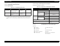
! EnhancedMicroGray installed (available only in 600dpi and 300dpi. automatically
EPSON EPL-5800 is non-impact page printer with semi-conductor laser and
electrophotographic technology.
! RITech installed (available only in 600dpi and 300dpi. Automatically switched
1.1.1 Features
SOFTWARE FEATURE
ENGINE FEATURES
! The following modes and resolution are supported.
Table 1-2. Supporting Modes
Off at 1200dpi)
Off when 1200dpi is selected.)
! Compact and lightweight, A4 support engine
Mode
! Resolution/ printing speed: See table below.
Table 1-1. Resolution and Printing Speed
1200dpi
600dpi
300dpi
ESC/Page
#
#
#
PCLXL
#
#
#
Resolution
Printing Speed
PCL5e
x
#
#
300dpi / 600 dpi
10ppm
ESC/P2
x
#
#
1200 dpi
5ppm
FX
x
#
#
1239X
x
#
#
PostScript
#
#
#
! Standard paper supply includes cassette-like universal paper tray (150 sheets) and
manual feed tray (one sheet)
! Option support for 500-sheets lower cassette (A4, Letter size)
CONTROLLER FEATURES
Optional
! NLSP is included in the main unit font ROM
! The number of built-in font added
ESC/Page:
PCL:
! High-speed controller, employing new CPU
" CPU = VR4310 / Clock = 133MHz
Note
49 → 84 fonts
45 → 80 fonts
! USB Revision 1.1 supported (for Widows 2000 USB PnP)
" 16 MB fitted as standard RAM and Expandable up to 256MB Max.
! Two standard interfaces
" IEEE1284 parallel interface
" USB interface (Windows 2000 supported)
! One Type B interface slot equipped (Level 3 supported)
! Euro Symbol supported
Product Description
Outline
9
EPSON EPL-5800
Revision B
1.2 Basic Specifications
1.1.2 Differences from EPL-5700
Table 1-3. Differences from EPL-5700
Item
EPL-5700
EPL-5800
Note
Engine speed
8ppm
10ppm
Real 1200dpi support
x
#
CPU performance
R4300-100MHz
R4310-133MHz
RAM capacity
(Standard / Maximum)
4MB / 36MB
16MB / 256 MB*1
RAM type
EDO RAM SIMM
SDRAM DIMM
Expansion ROM
ROM DIMM x 2
ROM DIMM*2 x 1
For Adobe PS 3 kit
Serial I/F
RS232C
USB
Support USB
Revision 1.1.
NLSP
ROM DIMM
Standard
PCL mode level
PCL5e
PCL6
Built-in fonts
45
80
For PCL
49
84
for ESC/Page
NLSP Bitmap3
Option
Standard
Included in the
main unit font
ROM.
PostScript (Optional)
Clone PS2
Adobe PS3
5ppm when
1200dpi is selected.
Printing Method:
Electrophotographic process using semiconductor laser
beam scanning and dry mono-component toner
Resolution:
600dpi / 1200dpi
(1200dpi is half speed control)
Printing Speed:
See table below.
Table 1-4. Printing Speed
600dpi
*1:
Maximum RAM capacity is possible when 256 MB SDRAM DIMM is implemented.
Even when 256 MB SDRAM DIMM is implemented, the maximum RAM capacity is
limited up to 256MB.
*2:
When PS option is implemented, other extension DIMMs (font etc.) cannot to be
implemented.
Product Description
1.2.1 Printer Basic Specifications
Paper Size
1200dpi
Main Unit
Lower Cassette
Unit*1
Main Unit
Lower Cassette
Unit*1
A4 or LT
10PPM minimum
10PPM minimum
5PPM minimum
5PPM minimum
LGL
8.4PPM minimum
--
4.2PPM minimum
--
B5
10PPM minimum
--
5PPM minimum
--
A5
10PPM minimum
--
5PPM minimum
--
*1:
Printing speed is lower when printing custom paper size because the automatic cleaning is
carried out.
Basic Specifications
10
EPSON EPL-5800
First Print:
Revision B
Paper Supply:
See table below.
See table below.
Table 1-5. First Print
600dpi
Paper Size
Table 1-6. Paper Supply
1200dpi
Main Unit
Lower Cassette
Unit*1
Main Unit
Lower Cassette
Unit*1
A4 or LT
18sec maximum
19sec maximum
27sec maximum
29sec maximum
LGL
19sec maximum
--
29sec maximum
--
B5
18sec maximum
--
26sec maximum
--
A5
18sec maximum
--
24sec maximum
--
*1:
Paper Feed
Method
Capacity
Paper Size
Paper Thickness
Paper Tray
(Fixed)
150
sheets*1
Standard or custom paper sizes
within the following ranges;
76.2x127 to 215.9x355.6mm
(A4, JIS-BIDS, A5, Letter,
Government Letter, Executive,
Legal, Government Legal, F4, Half
Letter)
Plain paper
60 to 90 g/m2
(16 to 24 lb)
10 sheets
Envelops
(Monarch, C10, DL, C5, C6,
International-B5, Labels,
Transparencies, Thick Papers)
Plain paper
60 to 90 g/m2
(16 to 24 lb)
Thick paper
90 to 163 g/m2
Special paper
(Labels, Transparencies)
Manual feed
slot*2
1 sheet
Standard or custom paper sizes
within the following ranges;
100x148 to 215.9x355.6mm
Plain paper
60 to 90 g/m2
(16 to 24 lb)
Thick paper
90 to 163 g/m2
Special paper
(Labels, Transparencies)
Lower
Cassette
Unit*1,*3
500
sheets*1
A4 or LT
Plain paper
60 to 90 g/m2
(16 to 24 lb)
Printing speed is lower when printing custom paper size because the automatic cleaning is
carried out.
Warm-up Time:
[At 23°C, rated voltage]
" 22sec Max.
(From when powered on until “Ready” is displayed)
" 10sec Max.
(Recovering from Standby mode)
Product Description
*1:
Using 75 g/m2 (20lb) paper
*2:
Feed one sheet at a time from the top of the paper tray when manual feed.
*3:
The fixe size cassette (A4 or LT) can be installed. Maximum paper capacity including the
paper tray is 650 sheets.
Basic Specifications
11
EPSON EPL-5800
Paper Size:
Revision B
See table below.
Consumables:
" Toner cartridge (user replaceable)
Table 1-7. Paper Size
Paper
Plain
paper
Special
paper
*1:
Paper Size
(mm / inch)
Size
Paper
Tray
Manual
Feed Slot
Lower
Cassette
Unit*1
#
" Photoconductor unit (user maintenance item)
Applicable paper sizes:
" Paper tray:
A4
210x297
#
#
A5
148x210
#
#
paper width
paper length
JIS-B5
182x257
#
#
" Manual feed slot:
LT
215.9x279.4 (8.5x11”)
#
HLT
139.7x215.9 (5.5x8.5”)
#
#
LGL
215.9x355.6 (8.5x14”)
#
#
EXE
184.15x266.7 (7.25x10.5”)
#
#
GLG
215.9x330.2 (8.5x13”)
#
#
GLT
203.2x266.7 (8x10.5”)
#
#
F4
210x330
#
#
3”x5”
76.2x127 (3x5”)
#
MON
98.43x190.5 (37/8x7 1/2”)
#
#
C10
104.78x241.3 (41/8x9 1/2”)
#
#
DL
110x220
#
#
C5
162x229
#
#
C6
114x162
#
#
I-B5
176x250
#
#
16MO
198x275
#
#
paper width
paper length
#
" 2nd cassette:
76.2mm (3 inch) to 215.9mm (8.5 inch)
127mm (5 inch) to 355.6mm(14 inch)
110mm (3.9 inch) to 215.9mm (8 inch)
148mm (5.8 inch) to 355.6mm(14 inch)
Supported paper size = A4, Letter
Paper-feed reference:
Center line reference for each paper size
Output paper capacity:
[Face-down]
Max. 100 sheets
(with standard paper immediately after unpacked)
[Face-up]
Max. 20 sheets
(with standard paper immediately after unpacked)
* Switching between face-up/face-down is made by
manually operating the lever on the top of the printer.
Dimensions:
387W x 475D x 338 H (mm)
(Main unit only)
Weight:
Approx. 7kg
(excluding consumables or options)
Supported size differs according to the market destination
Product Description
Basic Specifications
12
EPSON EPL-5800
Revision B
Power Supply:
1.2.2 Process Specification
" 100V model (compatible with 100/120V supply)
120V±10%
50/60Hz 3Hz
" 200V model (compatible with 100/120V supply)
220V~240V±10%
Power Consumption:
50/60Hz 3Hz
See table below.
Method:
Electrophotographic method using dry mono-component
developing
Light source:
Semiconductor laser
Exposure:
OPC (organic photoconductor) drum
Charging:
Rotary-brush charging method
Developing:
Exposed area development
Toner:
Mono-component non-magnetic toner
Transfer method:
Roller Transfer
Fusing:
Heat and pressure roller system
Density adjustment:
Bias variable adjustment by user is possible
Table 1-8. Power Consumption
100V
model
200V
model
220V to
240V
model
Max. rated current (TBD)
7.0A
5.9A
3.2A
Power
Consumption
Maximum
660W
690W
700W
Continuous printing,
average
270W
270W
270W
Standby
actual value
(TBD)
Heater ON
50W
50W
50W
Heater OFF
15W
15W
15W
Life:
180,000 sheets or 5 years, whichever comes first.
Noise:
[During standby]
30 db(A) max. (4-directional average)
[During operation]
48 db(A) max. (4-directional average) (T.B.D)
Ozone Concentration:
0.02 ppm max.
Toxicity:
OPC, toner, and plastic materials are all non-toxic.
Product Description
Basic Specifications
13
EPSON EPL-5800
Revision B
" Folded, curled, or torn paper.
1.2.3 Paper Specification
" Irregularly shaped paper or paper with non-perpendicular corners.
1.2.3.1 Paper Type
Standard paper:
Xerox 4024 DP paper 20 lb (75 g/m2)
Plain paper:
60 ~ 90 g/m2 (16 ~ 24 lb)
Photocopier paper, bond paper, recycled paper
" Sheets of labels that peel off easily.
" Paper with glue, staples, or clips attached.
" Special inkject paper superfine paper, glossy film, etc.
" OHP film for color laser printers or photocopiers.
Special paper:
" Sheets already printed on other color or black/white laser printers or
" Labels
photocopiers.
" Transparencies
" Sheets of paper stuck together.
" Colored paper
" DTP paper
NOTE: When printing on pre-printed papers, the paper may not feed correctly
due to paper particles adhering to the paper-feed roller. If this occurs,
clean the printer as described in 6.1.1 "User Maintenance on Main Unit".
" Letter-head
1.2.3.2 Paper Feeding
" Thick paper (90 to 163 g/m2)
NOTE: lb: Ream weight= lb/500 sheets/17”x22”
g/m2: 1 g/m2 =0.2659763 lb
Table 1-9. Paper Feeding
Special paper
C A U T IO N
Do not use any of the paper types listed below with this printer.
They may cause defective printing, paper jams, or damage to the
printer.
" Carbon paper, non-carbon paper, thermal paper, pressure-sensitive paper,
acidic paper.
" Paper previously printed in a thermal printer or inkject printer.
" Extra thick or extra thin paper.
" Damp paper.
" Surface-coated paper or surface-treated color paper.
" Extra smooth or glossy paper. Extra rough paper. Paper with significantly
different roughness on each surface.
Paper
source
Standard
paper
Plain
paper
(60 to 90
g/m2)
Paper tray
#
Lower
cassette
unit*
#
OHP
Labels
Thick
paper
(90 to 163
g/m2)
Envelops
(MON,
C10, DL,
C5, C6)
$
∆
∆
∆
∆
$
x
x
x
x
#: Paper feeding reliability and image quality guaranteed.
$: Paper feeding reliability and image quality guaranteed.
Restricted to normally used paper types only.
#: Paper feeding and printing are possible.
Restricted to normally used paper types only.
x: Paper feeding not possible.
*: Option
" Paper with punched holes or perforations.
Product Description
Basic Specifications
14
EPSON EPL-5800
Revision B
1.2.3.3 Printable Area (Engine)
1.2.4 Reliability, Durability, Serviceability
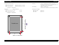
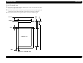
Guaranteed print area:
MPBF:
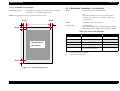
Entire paper area except for a 4 mm margin at each edge.
(See Figure 1-1, "Guaranteed print Area").
25, 000 sheets min. one-sided printing
Note:
This figure indicates the mean pages until a failure
requiring part replacement or a failure that the user
cannot remedy.
NOTE: The printable area may depend on the printer mode.
4 m m
4 m m
MTBF:
3,000 hours (10 month) minimum
Paper Feeding:
See table below.
Applicable conditions for the following figures is using
standard paper under standard environmental conditions.
4 m m
Table 1-10. Paper Feed Reliability
Error type
G u a ra n te e d
p r in t a r e a
Paper Tray
Lower Cassette Unit
1/2000 max.
←
Paper misfeed
1/2000 max.
←
Multiple-sheet feed rate
1/500 max.
←
Paper creasing
1/1000 max.
←
Leading edge folded
1/1000 max. for 1C or more.
Less than 1C not included.*2
←
Paper-jam
rate*1
*1:
Not including multiple-sheet feed.
*2:
1C indicates 1mm corner fold.
4 m m
Figure 1-1. Guaranteed print Area
Product Description
Basic Specifications
15
EPSON EPL-5800
Revision B
Printing start position accuracy:
" Main scan direction:
Reference position (c) ± 2.0 mm
" Sub scan direction:
Reference position (a) ± 2.5 mm
Durability:
5 years or 180,000 sheets, whichever comes first.
Including parts replaced by service technicians. (See 6.1.3
"Maintenance by Service Technicians")
Serviceability:
MTTR = 30 minutes max.
(Time for service technician to locate and repair a failure.)
See Figure 1-2, "Paper Skew".
Paper skew:
With A4 landscape;
Output paper curl height:
" Main scan direction (|c-d|):
± 2.0 mm
" Plain paper:
±30mm max.
" Sub scan direction (|a-b|):
±1.5 mm
" OHP:
±20mm max.
See Figure 1-2, "Paper Skew".
c
a
b
f
P a p e r fe e d in g d ir e c tio n
P r in ta b le a r e a
d
e
Figure 1-2. Paper Skew
Product Description
Basic Specifications
16
EPSON EPL-5800
Revision B
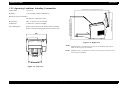
1.2.5 Operating Conditions Including Consumables
547 (D) (with the top cover and paper feed cover open)
Temperature:
10 to 35 °C
Humidity:
15 to 85% RH (without condensation)
Illumination:
3,000 lx max. (no direct sunlight)
Surrounding space:
Keep the space shown in the figures below around the
printer to ensure normal printer operation. (Units: mm)
416 (H) (with the top cover open)
Max. 1° tilt front -rear or left-right
338 (D) (when using the output tray)
Horizontality:
362 (D) (when using the output tray extension)
Barometric pressure (altitude):
760 hPa min. (2500 meters max.)
Figure 1-4. Right View
NOTE: Additional space of 150mm is necessary on the backside of the printer
when the Face-up tray is installed.
NOTE: Additional space of 125mm is necessary over the printer when the Lower
cassette unit is installed.
Figure 1-3. Top View
Product Description
Basic Specifications
17
EPSON EPL-5800
Revision B
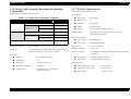
1.2.6 Storage and Transport Environments Including
Consumables
Temperature and humidity: See table below.
" Pulse width:
50 to 1000 ns
Main Unit
" Pulse polarity:
+/−
0 to 35 °C
" Repetition:
asynchronous
High temperature
0 to 40 °C
" Modes:
common/normal
Low temperature
-20 to 0 °C
" Voltage:
1kv (no component damage to 2kv)
Conditions
Normal conditions
Severe conditions
(1/30 of total storage
period)
Humidity
Normal Conditions
30 to 85% RH
Severe conditions
(1/30 of total storage
period)
These items do not include the options.
AC line noise:
Table 1-11. Temperature and Humidity Conditions
Temperature
1.2.7 Electric Characteristics
High humidity
85 to 95% RH
Low humidity
10 to 30% RH
Storage period
18 months from
manufacture
Barometric pressure:
460 to 760 hPa
Dropping:
No abnormalities according to JIS Z0200-1994 Level 1.
Free drop directions: 1 corner, 6 faces, 3 edges
Transient outage:
DIP 100% (at rated voltage-10%) for one cycle
with normal print quality.
Electrostatic tolerance:
" Up tp ±10 kv:
No hardware error
" Up tp ±15 kv:
No component damage
Surge current:
1/2 cycle, 50A max.
Insulation resistance:
10 M Ω min.
Dielectric strength:
No breakdown when the following voltages are applied for
one minute.
Vibrations:
" Frequency
5 to 100 Hz, 100 to 5 Hz
" 100V model:
AC 1000V (Primary to chassis)
" Acceleration
1G
" 200V model:
AC 1500V (Primary to chassis)
" Sweep time
10 minutes (each way)
" Direction of vibrations
3 directions
" Vibration time
60 minutes in X, Y, Z directions
(total 180 minutes)
Product Description
Leakage current:
" 100 V model, 100 V input:
0.25mA or less
" 100V model, 100 V input:
3.5mA or less
" 200V model:
3.5mmA or less
Basic Specifications
18
EPSON EPL-5800
Revision B
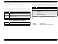
1.2.8 Applicable Standards and Regulations
EMC
The engine specification meets the following standards and regulations.
According to their intended destination, some standards and regulations apply to a
product with controller.
SAFETY STANDARDS
Table 1-12. Safety Standards
Model Name
Table 1-14. EMC
Model Name
100V model
CNS 13438 (Taiwan)
FCC Part 5 Subpart B Class B/CSA C108.8 Class B
200V model
EC, EMC Directive 89/336/EEC
EN61000-3-2
EN61000-3-3
EN50082-1
CiSPR 24
AS/NZS 3548 Class B (Australia)
GB9254 (CISPR 22) (China)
Applicable Standard
100V model
UL 1950 3rd
CSA 22.2 No.950
200V model
TÜV-GS (EN60950)
CCIB, Russian Safety Standards, Singapore Safety Standards, Hong Kong
Safety Standards (IEC950)
SAFETY REGULATIONS (LASER RADIATION)
Table 1-13. Safety Regulations (Laser Radiation
Model Name
Applicable Standard
Applicable Standard
Power consumption:
Complies with International Energy Star Program
standards.
Others:
" Toner:
No effects on human health (OSHA, TSCA, INECS,
Labor Safety Law, CSCL.)
" OPC:
No effect on human health (OSHA)
100V model
FDA (NCDRH) Class1
" Ozone:
UL478 (5th edition)
200V model
TÜV-GS (EN60825-1)
" Materials:
SWISS environmental laws (not including Cds)
Product Description
Basic Specifications
19
EPSON EPL-5800
Revision B
1.2.9.2 Storage and Transport Environments
1.2.9 Consumable Specifications
Temperature and humidity conditions:
1.2.9.1 Specifications
Table 1-16. Temperature and Humidity Conditions
Table 1-15. Consumable Specifications
Name
Developer and
Toner cartridge
Photoconductor
unit
*1:
Contents
Life*1
-Developer
-Black, one-component,
non-magnetic toner
Average
6,000 sheets
-OPC drum (organic
photoconductive conductor)
-Charger
Average
20,000sheets
approx. 0.5 kg
Temperature
Normal conditions
Severe conditions
(1/30 of total storage
period)
approx. 0.3 kg
These figures for printed sheets are based on continuous printing of A4 size sheets with
5% image coverage. Actual usage will vary depending on image coverage and printing
conditions such as continuous printing, intermittent printing, saturated printing and toner
save.
Toner Cartridge and
Photoconductor Unit
Conditions
Weight
Humidity
0 to 35 °C
High
temperature
35 to 40 °C
Low
temperature
-20 to 0 °C
Normal Conditions
Severe conditions
(1/30 of total storage
period)
30 to 85% RH
High humidity
85 to 95% RH
Low humidity
10 to 30% RH
Barometric pressure
61.3 to 101.3 kPa
Storage period
Dropping:
18 months from manufacture
(Packed)
No abnormalities according to JIS Z0200-1994 Level 1.
Free drop directions: 1 corner, 6 faces, 3 edges
Vibrations:
Product Description
" Frequency
5 to 100 Hz, 100 to 5 Hz
" Acceleration
1G
" Sweep time
10 minutes (each way)
" Direction of vibrations
3 directions
" Vibration time
60 minutes in X, Y, Z directions
total 180 minutes
Basic Specifications
20
EPSON EPL-5800
Revision B
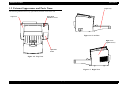
1.3 External Appearance and Parts Name
Paper Tray
The following illustrations are top, right and left, and back views of the unit.
Top Cover
Paper Feed
Switchover Lever
Figure 1-6. Left View
Right Cover
(Option Cover)
Operation
Panel
Figure 1-5. Top View
Figure 1-7. Right View
Product Description
Basic Specifications
21
EPSON EPL-5800
Revision B
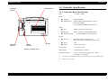
Ventilation Fan
Parallel I/F
connector
1.4 Controller Specification
1.4.1 Controller Basic Specification
CPU:
VR 4310 133MHz
RAM:
" Standard:
16MB (SDRAM)
" SIMM Option:
32MB, 64MB, 128MB (SDRAM, one slot)
Maximum 256MB
(when 256MB SDRAM DIMM mounted)
ROM:
" Font:
4Mbyte (mounted on main board)
" Program:
4Mbyte (mounted on ROM DIMM board)
" Expansion ROM:
one ROM DIMM slot (for PS option)
Host I/F:
Type-B I/F
Card slot
USB I/F
Connector
Figure 1-8. Back View
Product Description
AC Inlet
" Parallel:
IEEE1284 compliant, bidirectional,
B-type connector, Compatibility, Nibble, ECP
" Serial:
USB
" Option:
Type B slot (one slot)
Control Panel:
4 switches, 6 LED
Miscellaneous:
Embeded engine controller
Installed emulations:
PCLXL, PCL5e, GL/2, FX, ESCP2, 1239X,
ESC/Page*1, PostScrtipt3*2
*1:
The IES does not support ESC/Page. Only the ESC/Page driver can print ESC/Page.
*2:
PostScript3 is an option.
Controller Specification
22
EPSON EPL-5800
Revision B
1.4.2 Controller Configuration
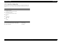
EPL-5800 controller allows the following settings to be configured according to the
market destination. The settings are made with jumpers, and must thus be set at the
factory.
JUMPER SETTING
! Packaged resistance
RJ2, RJ3, RJ5, RJ7, RJ10, RJ12, RJ13
! Unpackaged resistance
RJ1, RJ4, RJ6, RJ8, RJ9, RJ11, RJ14
! Packaged
JP7
! Unpackaged
SWD1, JP6
! JP7
1-2 side
DESTINATION SETTINGS A4/LETTER SELECTION
! For North and South America/ 120V model:
Letter setting
! Other destinations:
A4 setting
Product Description
Controller Specification
23
EPSON EPL-5800
Revision B
The default device ID setting for EPL-5800 is as follows.
1.4.3 External I/F specification
***1;
MFG:EPSON;
CMD:PJL,EJL,ESCPL2,PRPXL24-01,PCL,HPGL2-01,ESCPAGE-04,PCLXL***2;
MDL:***3;
CLS:PRINTER;
DES:***4;
EPL-5800 has the following host interfaces as standard.
! IEEE1284 parallel interface
! USB interface
! Optional Type-B I/F Card slot
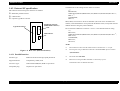
Parallel I/F connector
(IEEE1284 B connector)
Type-B i/F card slot
MFG, MDL, CID of Device ID are re-definable. (this must not be included in the
manual.) And CID field does not respond with the default value, but responds with the
defined character string only when redefined.
Device ID when redefined is as follows. “xxxxx” is user-defined character string.
***1;
MFG:xxxxx;
CMD:PJL,EJL,ESCPL2,PRPXL24-01,PCL,HPGL2-01,ESCPAGE-04,PCLXL***2;
MDL:xxxxx;
CLS:PRINTER;
DES:xxxxx;
CID:xxxxx;
USB connector
NOTE:
Figure 1-9. Rear View (Interface bracket)
*1:
The hexadecimal value “the total number of Device ID characters + 2” is input.
*2:
Following text string is added when Adobe PS 3 kit ROM DIMM option is installed.
“,POSTSCRIPT”
1.4.3.1 Parallel Interface
Interface type:
IEEE1284 bi-directional high-speed parallel I/F
Supported modes:
Compatibility, Nibble, ECP
Connector Type:
57RE-40360-830B(D7A) DDK or equivalents
Compatible plug:
Amphenol or equivalents
Product Description
*3:
The model name EPL-5800
*4:
DES is the text string that MFG and MDL is connected by a spcace.
“EPSON EPL-5800” for EPSON EPL-5800.
Controller Specification
24
EPSON EPL-5800
Revision B
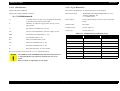
1.4.3.2 USB Interface
1.4.3.3 Type B Interface
Supports Windows USB PnP.
EPL-5800 is equipped with one Type-B option I/F slot as standard.
Supports the 18-digit USB ID as follows:
Main System Type:
MTP1200dpi, PW10200dt1200dpi, PRG(****)rev,
AP500ma, SPD0fast, D4
****: ROM version
**P++YYMMDDhhmmssR
**:
A number of 00 to 99 and “01” is assigned for this model.
Acquired in serial order for each model.
Printer Name:
Factory default setting is the same as one of Product
Name.
P:
Identifier. “P” indicates a page printer. Always “P” for
page printers.
Product Name:
EPL-5800
Emulation Type:
See the Table 1-17.
++:
PC number of assembly line. (00~99)
Entity Type:
See the Table 1-17.
YY:
The year of assembled date. (lower two digits; 00~99)
MM:
The month of assembled date. (1~12)
DD:
The assembled date (1~31)
hh:
Hour of assembled time. (0~23)
mm:
Minute of assembled time. (0~59)
ss:
Second of assembled time. (0~59)
R:
Reserved and always “0” in this model.
Table 1-17. Emulation Type and Entity Type
Emulation
Device ID in Printer Class conforms to 1.4.3.1 "Parallel Interface"..
C A U T IO N
The USB ID is stored on EEPROM of the main board, and you have to
re-assign the ID when you replace the main board to new one in
repair.
Refer to Chapter 5 “Adjustment” for the details.
Product Description
Emulation Type
Entity Type
PCLXL
PCLXL
EPSONPCLXL
LJ4
PCL5E-00
EPSONPCL5
GL/2
HPGL2-01
EPSONHPGL2
PS
POSTSCRIPT-00
LaserWriter
FX
ESCP9-84
EPSONFX
ESCP2
ESCPL2-00
EPSONLQ2
1239X
PRPXL24-01
EPSONPRPXL24
ESC/Page
ESCPAGE-04
EPSONPAGE4
Controller Specification
25
EPSON EPL-5800
Revision B
! When Emulation is set to “Auto”, the following Entity Type will be returned.
" If PS is not installed;
EPSONPAGE4, EPSONCL5, EPSONLQ2, EPSONHPGL2, EPSONFX,
EPSONPRPXL24
" If PS is installed;
LaserWriter, EPSONPAGE4, EPSONPCL5, EPSONLQ2, EPSONHPGL2,
EPSONPRPXL24
! When Emulation is fixed, the following Entity Type will be returned.
" Default Emulation: EPSONPAGE4
NOTE: The number of entity types returned to the host depends on the
specification of Type B interface.
! Emulation Type
" If Emulation is set to Auto;
If PS3 is OFF:
If PS3 is ON:
AUTO (Emulation Type 1, 2, 3...)
EJL (POSTSCRIPT-00, other Emulation Type 1, 2, 3...)
" If Emulation is fixed;
EJL (Default Emulation, other Emulation Type 1, 2, 3...)
Product Description
Controller Specification
26
EPSON EPL-5800
Revision B
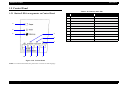
1.5 Control Panel
Table 1-18. Buttons and LEDs
1.5.1 Button/LED Arrangements on Control Panel
4
5
3
6
2
No.
Name
Note
1
On line LED
Color: Green
2
Data LED
Color: Yellow
3
Continue LED
Color: Red
4
Paper LED
Color: Yellow
5
Toner LED
Color: Yellow
6
Memory LED
Color: Yellow
7
On Line switch
8
Form Feed switch
9
Continue switch
10
Alternate switch
1
10
9
8
7
Figure 1-10. Control Panel
NOTE: For Taiwan and China, the panel sheet is written in each language.
Product Description
Control Panel
27
EPSON EPL-5800
Revision B
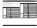
Table 1-19. Function Setting (1)
1.5.2 List of Panel Settings
EPL-5800 has no LCD on the control panel, so it is impossible to make function
settings from the control panel. Function settings can be made using “RCP”. The
following tables are lists of the printer setting items.
Underline indicates the factory default setting.
Menu
Printing Menu
! Function Setting (1)
Table 1-19. Function Setting (1)
Menu
Test Menu
Item
Item
Paper Source
Auto, MP, LC*4
Page Size
A4*5, A5, B5, LT*5, HLT, LGL, GLT, GLG,
EXE, F4, MON, C10, DL, C5, C6, IB5, CTM
Wide A4
Off, On
Orientation
Port, Land
Copies
1-999
Quantity*6
1-999
Manual Feed
Off, On
Resolution
600, 1200*7, 300
Value
Status Sheet
AUX Status Sheet*3
PS3 Status Sheet*1
PS3 Font Sample*1
Dot Correction
Off, On
ESC/Page Font
Sample*2
Skip Blank
LJ4 Font Sample
Auto Eject Page
Off, On
MP Mode
Normal, Last
MP Tray Size
A4*5, A5, B5, LT*5, HLT, LGL, GLT, GLG,
EXE, F4, MON, C10, DL, C5, C6, IB5
LC Size*4
A4, LT
MP Type
Plain, Preprinted, Letterhead, Recycled, Color,
Trnsprncy, Labels
LC Type*4
Plain, Preprinted, Letterhead, Recycled, Color
Tray Menu
ESCP2 Font Sample
FX Font Sample
I239X Font Sample
Emulation Menu
Value
Parallel
Auto, LJ4, ESCP2, FX, I239X, PS3*1, GL2
USB
Auto, LJ4, ESCP2, FX, I239X, PS3*1, GL2
AUX*3
Auto, LJ4, ESCP2, FX, I239X, PS3*1, GL2
Product Description
Control Panel
Page*8
Off, On
28
EPSON EPL-5800
Revision B
Table 1-19. Function Setting (1)
Menu
Config Menu
Setup Menu
Parallel Menu
Item
Value
RITech*9
On, Off
Toner Save
Menu
Value
Use, No Use
Off, On
AUX Config*13
No, Yes
Density
3, 4, 5, 1, 2
Buffer Size*11
Normal, Maximum, Minimum
Top Offset
-99.0 ~ 0.0 ~ 99.0mm
(0.5mm increments)
Left Offset
-99.0 ~ 0.0 ~ 99.0mm
(0.5mm increments)
Size Ignore
Off, On
Auto Cont
Off, On
Page Protect
Auto, On
Image Optimum
Auto, Off, On
Paper Type*10
Normal, Thick W, Thick N, Trnsprnc
Time out
0, 5 ~ 60 ~ 300
Standby
Continue, Stop
Lang
English, Française, Deutsch, ITALIANO,
ESPANOL, SVENSKA, Dansk, Nederl,
SUOMI, Português
Toner
E****F, E***$F, E**$$F, E*$$$F,
E$$$$F
Toner Out
Disable, Enable
SelecType Unit
0 ~ 99999999
Parallel
I/F*11
Buffer
Product Description
*1:
This item can be selected only when the optional Adobe PS 3 kit is installed.
*2:
Cannot be selected / changed by RCP etc. and is not printed on the Status Sheet.
*3:
This item can be selected only when the Type B I/F option is installed.
*4:
Displayed only when the optional lower cassette unit is installed. Paper sizes are display
only.
*5:
LT= default value for Letter-model controller
A4= default value for A4-model controller
*6:
Can be set only with the printer driver. Not printed on Status Sheet. Can be to set with
EJL or PJL, but it is valid only when the installed RAM is 64MB or more. (The firmware
does not verify the installed RAM capacity, but the printer driver does. This must not be
stated in the manual.)
*7:
Effective only for ESC/Page, PCLXL and PostScript. When other mode is selected, it will
be printed in 600dpi.
*8:
Valid for PCL5e, ESC/Page, ESC/P2, FX and 1239X.
*9:
When resolution is set to 1200dpi by mode setting, RITech becomes OFF regardless of
this item.
*10:
TBD
*11:
When this item is changed, reading with EJL and printing on the Status Sheet are
immediately reflected, but become valid after warm boot or at power on again.
*12:
Appears only when the optional Type B interface card is installed.
Network card configurations cannot be made from the printer side. Use the utility that
comes with each card.
*13:
Display only when Type B Level 3 card is installed. This value cannot be changed and
always set to “No”.
Nibble, ECP, Off
Size*11
USB I/F*3
Buffer
NOTE:
On, Off
Fast, Normal
Bi-D
AUX Menu*12
Item
AUX I/F*11
Speed
USB Menu
Table 1-19. Function Setting (1)
Size*11
Normal, Maximum, Minimum
On, Off
Normal, Maximum, Minimum
! Function setting (2)
Control Panel
29
EPSON EPL-5800
Revision B
Table 1-20. Function Setting (2)
Table 1-20. Function Setting (2)
Menu
ESC/Page
Menu*1
Item
Auto CR
On, Off
Auto FF
On, Off
CR Function
CR, CR+LF
LF Function
CR+LF, LF
FF Function
CR+FF, FF
Error Code
Ignore, Space
Avoid Error
Off, On
PGI
On, Off
Product Description
Menu
Value
LJ4 Menu
Control Panel
Item
Value
Font Source
Resident, DIMM, Download
Font Number
0 ~ available (Max 65535)
Pitch*2
0.44 ~ 10.00 ~ 99.99 cpi
(0.01 cpi increments)
Height*2
4.00 ~ 12.00 ~ 999.75 pt
(0.25 pt increments)
SymSet*10
IBM-US, Roman-8, Roman-9, ECM94-1, 8859-2
ISO, 8859-9 ISO, 8859-10 ISO, 8859-15 ISO,
PcBlt775, IBM-DN, PcMultiling, PcE. Europe,
PcTk437, PcEur858, Pc1004, WiAnsi, WiE.
Europe, WiTurkish, WiBALT, DeskTop, PSText,
VeInternati, VeUS, MsPublishin,
Math-8, PsMath, VeMath, PiFont, Legal, UK,
ANSI ASCII, Swedis2, Italian, Spanish, German,
Norweg1, French2, Windows, McText,
PcIcelandic, PcLt774, PcTurk1, PcPortugues,
PcET850, PcTurk2, PcCanFrench, PcS1437,
PcNordic, 8859-3 ISO, 8859-4 ISO, WinBaltic,
WiEstonian, WiLatvian, Mazowia, CodeMJK,
BpBRASCII, BpAbicomp, PcGk437, PcGk851,
PcGk869, 8859-7 ISO, WiGreek, Europe3,
PcCy855, PcCy866, PcLt866, 8859-5 ISO,
WiCyrillic, Bulgarian, PcUkr866, Hebrew7, 8859-8
ISO, Hebrew8, PcHe862, Arabic8, PcAr864,
8859-6 ISO, OCR A, OCR B
Form
5 ~ 60*3 ~ 64*3 ~ 128 Lines
Source SymSet
0 ~ 277 ~ 3199
Dest Symset
0 ~ 277 ~ 3199
CR Function
CR, CR+LF
LF Function
LF, CR+LF
Tray Assign
4, 4K, 5S
30
EPSON EPL-5800
Revision B
Table 1-20. Function Setting (2)
Menu
GL2 Menu
PS Menu*5
Item
Table 1-20. Function Setting (2)
Value
GL-Mode
GLlike, LJ4GL2
Scale
Off, A0, A1, A2, A3
Origin
Menu
Value
Font
Courier, Prestige, Roman, Sans serif, Roman T,
Orator S, Sans H, Script,
OCR A, OCR B
Corner, Center
Pitch
10cpi, 12cpi, 15cpi, Prop.
Pen
Pen0, Pen1, Pen2*4, Pen3*4, Pen4*4, Pen5*4,
Pen6*4
Condensed
Off, On
End
Butt, Square, Triangular, Round
T. Margin
0.40 ~ 0.50 ~ 1.50 inch
(0.05 inch increments)
Join
Miterend, Meteredbeveled, Triangular, Round,
Beveled, None
Text
1 ~ 62*6 ~ 66*7 ~ available (Max 81) Lines
Pen0
0.05 ~ 0.35 ~ 5.00 mm
(0.05 mm Increments)
CGTable
Pen1
0.05 ~ 0.35 ~ 5.00 mm
(0.05 mm Increments)
Pen2*4
0.05 ~ 0.35 ~ 5.00 mm
(0.05 mm Increments)
Pen3*4
0.05 ~ 0.35 ~ 5.00 mm
(0.05 mm Increments)
PcUSA, Italic, PcMultilin, PcPortugue,
PcCanFrenc, PcNordic, PcTurkish2, PcIceLandic,
PcE.Europe, BpBRASCII, BpAbicomp, Roman-8,
PcEur858,
ISO Latin1, 8859-15 ISO, PcS1437, PcTurkish1,
8859-9 ISO, Mazowia, CodeMJK, PcGk437,
PcGk851, PCGk869, 8859-7 ISO, PcCy855,
PcCy866, Bulgarian, PcUkr866, Hebrew7,
Hebrew8, PcAr864, PcHe862
Country
USA, France, Germany,UK, Denmark, Sweden,
Italy, Spain1, Japan, Norway, Denmark2, Spain2,
LatinAmeric, Korea, Legal
Auto CR
On, Off
Auto LF
Off, On
Bit Image
Dark, Light, BarCode
ZeroChar
0, φ
Pen4*4
0.05 ~ 0.35 ~ 5.00 mm
(0.05 mm Increments)
Pen5*4
0.05 ~ 0.35 ~ 5.00 mm
(0.05 mm Increments)
Pen6*4
0.05 ~ 0.35 ~ 5.00 mm
(0.05 mm Increments)
Error Sheet
Off, On
Product Description
ESCP2 Menu
Item
Control Panel
31
EPSON EPL-5800
Revision B
Table 1-20. Function Setting (2)
Menu
FX Menu
Item
Table 1-20. Function Setting (2)
Value
Menu
Font
Courier, Prestige, Roman, Sans serif, Script, Orator
S, OCR A, OCR B
Pitch
Value
Font
Courier, Prestige, Gothic, Orator, Script, Presentor,
Sans serif
10cpi, 12cpi, 15cpi, Prop.
Pitch
10cpi, 12cpi, 15cpi, 17cpi, 20cpi, 14cpi, Prop.
Condensed
Off, On
Code Page
437, 850, 858, 860, 863, 865
T. Margin
0.40 ~ 0.50 ~ 1.50 ~ inch
(0.05 inch increments)
T. Margin
0.30 ~ 0.40 ~ 1.50 inch
(0.05 inch increments)
Text
1 ~ 62*8 ~ 66*9 ~ available (Max 81) Lines
Text
1 ~ 63 ~ 67 ~ available (Max 81) Lines
CGTable
PcUSA, Italic, PcMultilin, PcPortugue,
PcCanFrenc, PcNordic, PcTurkish2, PcIcelandic,
PcE. Europe, BpBRASCII, BpAbicomp, Roman-8,
PcEur88,
ISO Latin1, 8859-15 ISO
Auto CR
Off, On
Auto LF
Off, On
Auto Graphic
Off, On
Bit Image
Dark, Light
ZeroChar
0, φ
CharacterSet
1*8, 2*9
Country
I239X Menu
Item
USA, France, Germany, UK, Denmark, Sweden,
Italy, Spain1, Japan, Norway, Denmark2, Spain2,
LatinAmeric
Auto CR
On, Off
Auto LF
Off, On
NOTE:
Bit Image
Dark, Light, BarCode
*1:
Not displayed on the panel. Not printed on the status sheet. Not open to users.
ZeroChar
0, φ
*2:
Either is displayed depending on the type of pitch of the selected font. “Pitch” is displayed
for the fixed pitch font, and “Height” is for the proportional font.
*3:
Default value is 64 for A4-model controller and 60 for Letter-model controller.
*4:
Appears only in the GLlike mode.
*5:
Appears and can be set only when optional Adobe PS 3 kit is installed.
*6:
Factory default setting for Letter-controller.
*7:
Factory default setting for A4-controller.
*8:
Factory default setting for Letter-controller.
*9:
Factory default setting for A4-controller.
*10:
When “SymSet” value is changed and the font specified by Font Number does not have
its Symbol Set, Font Source and Font Number settings are automatically made as follows;
Product Description
Control Panel
32
EPSON EPL-5800
Revision B
Font Source = Resident, Font Number = 0
Due to this, to print by this symbol set, a font must be selected for which the Font Source
and Font Number Value are supported by this symbol set.
Product Description
Control Panel
33
EPSON EPL-5800
Revision B
! Stop
1.5.2.1 Setting Items (Model-dependent)
Described below are model-dependent specification details of the setting items for
EPL-5800.
“Toner Out” error occurs when the measurement of Toner counter reaches to the
level where “Toner Out” error occurs.
PAPER TYPE
MP MODE
Specifies the paper type loaded in the MP Tray.
When the paper source setting is “Auto” or not specified, MP mode determines the
priority of the sources.
Normal:
Last:
MP > LC (MP Tray has priority)
LC > MP (Lower Cassette has priority)
" Normal:
Normal paper
" Thick W:
Thick paper
" Thick N:
Thick and narrow paper like an envelop.
" Transprnc:
OHP sheets
TRAY ASSIGN
Tray Assign changes the assignment for the paper source select command (ESC&I#H).
Effective only for PCL mode.
Table 1-21. Tray Assign
The correspondence of
the parameter #
MP
LC
4
1
4
HP Laser Jet 4 compatible
4K
4
1
HP Laser Jet 000/5000/8000 compatible
5S
8
1
HP Laser Jet 5Si compatible
Note
TONER OUT
MP TYPE, LC TYPE
Specifies the paper type for MP Tray or LC.
When “Paper Source = Auto”, MP Type and LC Type is used to select a unit that
matches the paper type specified by the printer driver.
In a printer mode without such command, the same operation as when “Plain” is
selected is performed.
“Transpmcy” and “Label” cannot be set to LC Type. Other parameters are common to
MP Type.
The following table is the correspondence of “Paper Type” and “MP Type” setting and
the printer media
Specifies the printer operation when “Toner Out” occurs.
Table 1-22. Paper Type, MP Type, and the Printing Media
! Continue
Paper Type
MP Type
Printing Media
Normal
OHP
OHP
Normal
Other than OHP
Normal paper
Thick W
Any
Thick paper
Thick N
Any
Postcard/Envelop
Transprnc
Any
OHP
Printer does not produce “Toner Out” error and continues printing when
measurement of Toner counter reaches to the level where “Toner Out” error
occurs.
This setting does not influence to “Toner Low” warning.
This parameter is Factory default.
It is recommended to set to Stop when the printer is located at distant place
(network printer etc.) and user cannot see its printout soon.
Product Description
Control Panel
34
EPSON EPL-5800
Revision B
Table 1-23. Interface Settings
QUANTITY
This is the copy quantity setting when copying by quantity. This setting is specified
taking preference over the Copies setting. When the printing quantity is 2 or more, the
Copies setting will be 1.
I/F automatic
selection
This setting can be specified only with EJL or ESC/Page command and the setting
cannot be stored.
If data for 1 job data failed to be stored into printer, the warning “Collate was disabled”
will be displayed and the printer prints out only one quantity.
PARALLEL I/F, USB I/F, AUX I/F
Parallel
USB
Type B
#
#
#
Automatic selection
(all interfaces)
#
#
X
Automatic selection
(Parallel and USB)
#
X
#
Automatic selection
(Parallel and Type B)
X
#
#
Automatic selection
(USB and Type B)
X
X
X
Returns to the factory default after the
Reset All is performed or the power is
turned on again.
Not effective
Only interfaces that are set to “On” by the panel setting can be used by the automatic
selection.
All interfaces are set to “On” at the factory default setting.
Operations
#: On, X: Off
When use a fixed interface, set “On” only for the interface that to be used.
Changes to the interface setting will be effective after the Reset All is performed or the
power is turned on again.
If “Off” is set to all interfaces, they are reset to “On” after the Reset All is performed or
the power is turned on again. (It is not allowed to set “Off” to all interfaces.)
Table 1-23. Interface Settings
Using Fixed I/F
Parallel
USB
Type B
#
X
X
Only parallel can be used.
X
#
X
Only USB can be used
X
X
#
Only Type B and be used.
Product Description
Operations
Control Panel
35
EPSON EPL-5800
Revision B
1.5.3 Printer Messages
Printer messages are Status Message, Error Message, Warning Message, and Service
Call Error Message.
Status Message is displayed only when there are no error or during the initialization.
No two Status Messages displayed at the same time and Error Message is displayed in
the priority order.
Refer to the tables on following pages for each error indication.
Product Description
Control Panel
36
EPSON EPL-5800
Revision B
Table 1-24. Printer Message
Messages in LCD-Equipped Models
LED Indications
(When the printer is turned on.)
1. All the LED on.
2. All the LED off. This indicates the printer is checking ROM.
3. Paper LED is turned off, and Toner LED lights on. This indicates the printer is checking RAM. After checking RAM
has completed, Toner LED is turned off. Check if the expanded memory is recognized on the status sheet.
4. Memory LED is turned on. This indicates the printer is performing self-check.
5. The printer is now ready to print.
During the sequence above, if any service call error has detected, corresponding error message is indicated.
Messages in LCD-Equipped Models
Paper LED
Toner LED
Service Req. effff
Memory LED
Classification
Online LED
Data LED
Continue LED
Refer to 1.6 "Service Call Errors"
Status
Classification
Status
System Check
#
#
%
#
#
#
Status
Reset All
&
&
&
&
&
&
Status
Reset
&
&
&
#
#
Exiting Paper Jam
&
#
#
#
#
&
Error
Paper Jam
&
#
#
#
#
&
Error
Feed Jam
&
#
#
#
#
&
Error
Printer Open
&
#
#
#
#
&
Error
Manual Feed ssss tttt
&
#
#
#
#
&
Error
Paper Out sssss tttt
%
#
#
#
#
&
Error
Toner Out
#
&
#
#
#
&
Error
Paper Set sssss tttt
%
#
#
#
#
%
Error
Print Overrun
#
#
&
#
#
%
Error
Mem Overflow
#
#
&
#
#
%
Error
Invalid PS3
#
#
&
#
#
%
Error
Invalid Aux I/F Card
#
#
&
#
#
%
Error
Invalid ROM A
#
#
&
#
#
%
Error
Status
&: On'#: Off %: Flashing
Product Description
Control Panel
37
EPSON EPL-5800
Revision B
Table 1-24. Printer Message
Messages in LCD-Equipped Models
Paper LED
Toner LED
Memory LED
Online LED
Data LED
Continue LED
#
#
#
#
& or %
same as normal
data transfer
#
Write Error ROM A
#
#
&
#
#
&
Error
Collate was disabled
#
#
%
#
#
#
Warning
Check Paper Size
%
#
#
#
#
#
Warning
Image Optimum
#
#
%
#
#
#
Warning
Check Paper Type
%
#
#
#
#
#
Warning
Writing ROM A
Format Error ROM A
Classification
Status
No indication (EJL status will be supported)
Warning
Need memory
#
#
%
#
#
#
Warning
Form Feed
#
#
#
#
%
#
Status
Warning Up
#
#
#
&
#
#
Status
Toner Low
#
%
#
#
#
#
Warning
Offline
Online LED goes off
Status
Standby
#
#
#
#
#
#
Status
Ready
#
#
#
& or %
#
#
Status
&: On'#: Off %: Flashing
Product Description
Control Panel
38
EPSON EPL-5800
Revision B
1.6 Service Call Errors
! Explanation
An error generated that cannot be solved by user side.
! LED Condition
All LED on. (0.8 sec) → All LED off (0.2 sec) → Respective LED on specified by
error code (0.8 sec) → All LED off (0.2 sec)
This sequence is repeated in 2 sec interval.
Refer to the following Table 1-25 and Table 1-26 for details.
! Solution
Turn off the power and back on.
If an error still remains, see the indicated error code to check and replace the
concerning unit.
Product Description
Service Call Errors
39
EPSON EPL-5800
Revision B
Table 1-25. Service Call Error (Engine-Related)
Error Code
Explanation
Paper LED
Toner LED
Memory LED
Online LED
Data LED
Continue LED
E0003
Failure in fuser unit
&
#
#
#
#
&
E0004
Failure in main motor
#
&
#
#
#
&
E0005
Failure in fan motor
&
&
#
#
#
&
E0006
Failure in polygon motor
#
#
&
#
#
&
E0007
Failure in HVPS
&
&
&
#
#
&
E0009
Failure in laser-diode
&
#
&
#
#
&
E0014
Engine communication error
#
&
&
#
#
&
&: On'#: Off
]
Table 1-26. Service Call Error (Controller-Related)
Error Code
Explanation
Paper LED
Toner LED
Memory LED
Online LED
Data LED
Continue Lamp
C0017
CPU Error (Undefined interruption occurred)
#
#
#
&
#
&
C0081
CPU Error (TLB revising exception)
&
#
#
&
#
&
C0082
CPU Error (TLB mistake exception [Load/Fetch])
#
&
#
&
#
&
C0083
CPU Error (TLB mistake exception [Store])
&
&
#
&
#
&
C0084
CPU Error (Address error exception [Load/Fetch])
#
#
&
&
#
&
C0085
CPU Error (Address error exception [Store])
&
#
&
&
#
&
C0086
CPU Error (Bus error exception [Store])
#
&
&
&
#
&
C0087
CPU Error (Bus error exception [Load/Store])
&
&
&
&
#
&
C0088
CPU Error (SYSCALL exception)
#
#
#
#
&
&
C0090
CPU Error (Reservation command exception)
&
#
#
#
&
&
C0091
CPU Error (Coprocessor blank exception)
#
&
#
#
&
&
C0092
CPU Error (FPU exception)
&
&
#
#
&
&
C0093
CPU Error (TLB exception)
#
#
&
#
&
&
C0094
CPU Error (XTLB exception)
&
#
&
#
&
&
Product Description
Service Call Errors
40
EPSON EPL-5800
Revision B
Table 1-26. Service Call Error (Controller-Related)
Error Code
Explanation
Paper LED
Toner LED
Memory LED
Online LED
Data LED
Continue Lamp
C0095
CPU Error (Cash exception)
#
&
&
#
&
&
C0096
CPU Error (Trap exception)
&
&
&
#
&
&
C0097
CPU Error (FPU error exception)
#
#
#
&
&
&
C0098
CPU Error (Watch exception)
&
#
#
&
&
&
C0128
CPU Error (Undefined trap)
&
#
&
&
&
C0255
CPU Error (NMI exception)
&
&
#
&
&
&
C0256
CPU Error (Division by 0)
#
#
&
&
&
&
C0257
CPU Error (Arithmetic Overflow)
&
#
&
&
&
&
C0258
CPU Error (Break generated)
#
&
&
&
&
&
C0800
IPL Error (Controller failure)
&
#
#
#
#
#
C1000
Standard RAM error (No RAM at all, etc.)
#
#
&
#
#
#
C1001
Standard RAM error (Not enough for minimum stack, etc.)
&
#
&
#
#
#
C1002
Standard RAM error (Not enough for standard size, etc.)
#
&
&
#
#
#
C1003
Option RAM error
&
&
&
#
#
#
C1100
ROM checksum error (bit0-15)(font)
#
#
#
&
#
#
C1101
ROM checksum error (bit16-31)(font)
&
#
#
&
#
#
C1120
ROM checksum error (bit0-7)(program)
#
&
#
&
#
#
C1121
ROM checksum error (bit8-15)(program)
&
&
#
&
#
#
C1122
ROM checksum error (bit16-23)(program)
#
#
&
&
#
#
C1123
ROM checksum error (bit24-31)(program)
&
#
&
&
#
#
C1170
Option font ROM checksum error
&
#
#
#
&
#
C1180
Option ROM module A checksum error
#
&
#
#
&
#
C1181
Option ROM module B checksum error
&
&
#
#
&
#
C1185
Unsupported ROM module
#
#
&
#
&
#
C1190
Cartridge access unable
&
#
&
#
&
#
Product Description
Service Call Errors
41
EPSON EPL-5800
Revision B
Table 1-26. Service Call Error (Controller-Related)
Error Code
Explanation
Paper LED
Toner LED
Memory LED
Online LED
Data LED
Continue Lamp
C1200
EEPROM writing error
#
&
&
#
&
#
C1210
EEPROM writing limit
&
&
&
#
&
#
C1400
Engine initialization error
#
#
#
&
&
#
C1999
Other hardware error
#
&
&
&
&
#
C2000
Software error
&
&
&
&
&
#
&: On'#: Off
Product Description
Service Call Errors
42
EPSON EPL-5800
Revision B
1.7 Special Operation
EEPROM INITIALIZATION
The function described below are activated by holding the specified switches down
when turning the printer on.
This operation clears the contents of EEPROM with “00H” and set the factory default
parameters.
C A U T IO N
Table 1-27. Special Operation
Function
Key
Hex Dump
Form Feed
Toner reset
On Line + Form Feed
Photoconductor life reset
On Line + Continue
EEPROM initialization
On Line + Continue + Alt
Panel setting value initialization
Continue
Update program ROM
On Line + Form Feed + Continue + Alt
Note that this operation clears all setting information and a total print
counter value as well.
PANEL SETTING VALUE INITIALIZATION
This operation initialize all setting informaiton of common functional environment and
I/F specific functional environment and set the factory default values.
UPDATE PROGRAM ROM
HEX DUMP
This operation activates the Code ROM-DIMM update function.
All print data are printed in ASCII hexadecimal value. Any interface equipped with the
printer is valid for receiving the data in this mode. The following informaiton is
printed.
! A list of received data converted in ASCII hexadecimal value.
(Non-readable code is printed as “.”)
1.
By executing the operation, the printer starts normal power-on sequence. Keep
depressed all buttons until “Paper”, “Toner” and “Memory” LEDs are turned on after
completing RAM check.
2.
Next, release all the buttons and “Online” LED starts blinking and all other LEDs are
turned on. Approx. 3 seconds later, “Continue” and “Form Feed” LEDs are turned off
and this indicates that the printer is ready to receive the firmware data via parallel I/F.
3.
After completing update, “Online” LED is blinking and all other LEDs are turned off.
! Page number
TONER RESET
Performing this operation initialize the toner counter value to “EnnnnF”.
PHOTOCONDUCTOR LIFE RESET
Performing this operaiton initialize the photoconductor unit life counter to “100%”.
Product Description
Service Call Errors
43
EPSON EPL-5800
Revision B
1.8 Notes for Operation
1.8.1 Expansion RAM
When EPL-5800 runs out of memory, the Memory LED flashes or lights.
(Corresponds to “Mem Overflow”, “Image Optimum”, “Need Memory” or “Collate
was disabled”on the machines with LCD.)
In this case, any of the following measures may be taken;
" Reducing the resolution.
" Select “Halftone” when using Enhanced MicroGray.
" Reducing the receiving buffer size to “Minimum”.
" Use only one interface and set “Off” for other interfaces.
The only way to definitely avoid memory shortages is to install more memory.
(Commercially available SDRAM DIMMs for PCs: 168 pins, 64-bit with SPD)
1.8.2 Powering Off
EPL-5800 includes an internal non-volatile memory (EEPROM).
If the printer is powered off during the process of writing to non-volatile memory, the
writing operation to the non-volatile memory cannot be guaranteed. And therefore the
next time the printer is powered on or the “Reset All” is carried out, panel settings may
be initialized or a service call error may occur.
The non-volatile memory saves the function settings, and the following cases are those
in which the memory is rewritten, and therefore the printer should not be powered off;
" After the printer is powered on, until the OnLine LED lights.
" While the printer is printing.
(While the paper feed motor is operating.)
" While the Data LED is flashing or lights.
To stop the printer, either put it off line or carry out a Reset.
1.8.3 High-Temperature Components
The fuser unit inside the printer becomes hot, and therefore care must be taken not to
touch the fuser unit while opening the printer to clear a paper jam.
Product Description
Notes for Operation
44
CHAPTER
2
OPERATING PRINCIPLES
EPSON EPL-5800
Revision B
2.1 Operating Principles of Mechanism
2.1.2 Paper Feed Mechanism
2.1.1 Paper Path
Multi Paper Feed Tray
The following figure shows the major paper paths in the printer.
EPSON EPL-5800 has two paper feed methods as standard; multi paper feed tray (150
sheets) and manual feed (1 sheet). With the optional second paper feed unit (500 sheets),
EPSON EPL-5800 has three paper feed methods.
Paper once fed by the paper feed roller is carried through transfer roller → fusing roller →
paper exit roller and ejected to paper eject tray.
! When the paper feed solenoid (SL1) is turned ON, the driving power from the
main motor (M1) is transmitted to the paper feed roller via the paper feed clutch
(one-way clutch), and the paper feed roller rotates.
! At the same time, the push down cam rotates, and it lifts the tray lifting plate.
Paper on the tray is carried into the printer by the paper feed roller.
! Separation pad method is used in order to separate each paper and prevent feeding
the second paper together.
! Since there is no paper size sensor mechanism in the multi paper feed tray, the
Face-up Paper Eject
printer detects the length of paper by the ON period of paper feed sensor (PS1),
and judges the paper size. So, if the paper has the same length, the printer judges
the paper as the same size even its width is different.
Face-down Paper Eject
Ejecting
Print Head
Exposure
Fusing
Charging
Development
Multi paper Feed Tray
Transfer
Paper Feed
Photoconductor
Paper Feed
Second Paper Feed Cassette
(Option)
4121s020
Figure 2-1. Paper Path
Operating Principles
Operating Principles of Mechanism
46
EPSON EPL-5800
Revision B
Paper Feed Roller
Paper Feed Sensor
(PS1)
Push Down
Cam
When there is paper on the tray, the actuator stands up and the sensor is turned OFF.
When paper on the tray went out, the actuator falls into the hole of the tray and the sensor is
turned ON.
2.1.2.1 Second Paper Feed Unit (Option)
Paper Empty
Sensor (PE1)
MECHANISM
! Since the second paper feed unit does not have driven motor, driving power for
feeding paper and carrying paper (driving force from M1) is transmitted to the
second paper feed unit from the printer via the connecting gear. Paper feed method
is the same as for multi paper feed tray.
Tray Lifting Plate
! As separation method, the separation pad method is used for the multi paper feed
tray, but the separator claw is used for the second paper feed unit.
Tray
! The separator claw is the method that uses elasticity between the separator
installed at the paper fed cassette and the paper.
Only one sheet of paper is fed by one paper feed operation.
4121s021
Paper Feed Solenoid (SL1)
Paper Feed Clutch
! The paper feed solenoid (SL21) is controlled from the printer side via the relay
board (PWB-A) of the second paper feed unit.
During Paper Feeding
Waiting Mode
Push Down Cam
Tray
Relay Board
(PWB-A)
Paper
Connecting
Gear
Paper Empty
Sensor (PI21)
4121s023
4121s022
Paper Feed
Roller
Tray Lifting Plate
Figure 2-2. Paper Feed Operation
Paper empty sensor (PE1) is mounted on the upper part of the multi paper feed tray and it
detects paper empty on the multi paper tray.
Operating Principles
Paper Feed Solenoid
4121s024
PAPER EMPTY SENSOR
Figure 2-3. Second Paper Feed Unit Mechanism
Operating Principles of Mechanism
47
EPSON EPL-5800
Revision B
PAPER EMPTY SENSOR
Table 2-1. ON/OFF of SW21 on each cassette type
Paper empty sensor (PI21) is mounted on the relay board (PWB-A) of the second paper
feed unit and it detects paper empty in the second paper feed cassette.
When there is paper on the tray, the actuator stands up and the sensor becomes OFF.
When paper on the tray went out, the actuator falls into the hole of the tray lifting board and
the sensor becomes ON.
CASSETTE TYPE SENSOR
Cassette Type
SW21-1
SW21-2
SW21-3
A4
OFF
OFF
ON
B5
ON
ON
OFF
Letter
OFF
ON
OFF
Executive
OFF
ON
ON
No cassette or
cassette is not specified
OFF
OFF
OFF
ON
ON
ON
ON
OFF
ON
Cassette type sensor switch (SW21) with sector-shaped lever is mounted on the second
paper feed unit.
When the cassette for each paper size is inserted, the switch presser on the right side of each
cassette pushes the lever according to the paper size and it turns the cassette type sensor
ON.
This switch is the three-consecutive switch, and the printer distinguishes the cassette type
(paper size) by ON/OFF combination of three switches.
Lever
OFF
Cassette Type Sensor Switch (SW21)
ON
4121s026
Switch Presser
4121s025
Paper Feed
Cassette
SW21-3
SW21-2
SW21-1
Figure 2-4. Cassette Type Sensor Mechanism
Operating Principles
Operating Principles of Mechanism
48
EPSON EPL-5800
Revision B
2.1.3 Charging Process
Drum Cartridge
2.1.3.1 Overview
! It is charged by giving static electricity to OPC drum (Organic Photoconductor)
before laser exposure.
Rotation Brush
(Charging Brush)
! Surface of OPC drum is charged by rotating brush (charging brush) and precharging film.
Laser Exposure
Surface Abrasive
! Charging by the rotation brush (charging brush) and the pre-charging film has low
Paper Powder Cleaner
rate of ozone occurrence by corona discharge and also low voltage and excels in
homogeneity and stability of the electric potential because of direct charging to the
OPC drum.
! Electric potential on the surface of OPC drum after charging is about
-800V.
Pre-charging Film
Developing Sleeve
Roller
! A rotation brush (charging brush) rotates when drive from the main motor (M1) is
transmitted to the gear of the rotation brush (charging brush).
Transfer Roller
! Pre-charging film takes a pre-charge before the rotation brush (charging brush)
OPC Drum
takes a charge in order to improve efficiency of charging.
4121s030
Drum Cover
1
2
4110s031
4
1. Rotation Brush
(Charging Brush)
2. OPC Drum
(Photoconductor)
3 Earth
4.Charging Brush
(Charging Bias)
Figure 2-5. Charging Mechanism
Operating Principles
Operating Principles of Mechanism
49
EPSON EPL-5800
Revision B
2.1.4 Exposure Process
The laser beam from the print head creates an electrostatic latent image on the OPC drum
surface.
The following control is performed in order to find appropriate timing to print the image.
SUB SCANNING DIRECTION
(VERTICAL SCANNING DIRECTION)
! When the printer receives the PRINT signal, the polygon motor (M3) and the main
motor (M1) rotate, and the main motor (M1) starts the paper feeding operation.
! When the specified period of time passes after the end of fed paper turns the paper
Print Head Unit
OPC Drum
feed sensor ON (TOD signal), the main control board sends the VIDEO signal to
the print head, and printing starts.
! When moving on from the first line to the second line, the print starting position is
shifted down by delaying the VIDEO signal sending time.
MAIN SCANNING DIRECTION
(HORIZONTAL SCANNING DIRECTION)
SOS (Start of Scan) Sensor
(PWB-D)
! To unify the laser exposure timing emitted every one line of main scanning, the
SOS sensor is mounted on the laser diode control board (PWB-D).
Laser Diode
4121s028
Polygon Motor (M3)
4110s032
Figure 2-6. Exposure Mechanism
Operating Principles
Operating Principles of Mechanism
50
EPSON EPL-5800
Revision B
2.1.4.1 Printable area
! The main control board sends the VIDEO signal, which corresponds to the paper
size, to the engine (controller).
! The main control board determines the printing start position by TOD signal (sub
scanning direction) and the HSYNC signal sent by the engine (controller).
/HSYNC
/TOD
/VIDEO
! The print head starts laser exposure when it receives the VIDEO signal.
/VIDEO
4mm
Printable Area
4mm
Figure 2-7. Printable Area
Operating Principles
Operating Principles of Mechanism
51
EPSON EPL-5800
Revision B
2.1.5 Development Process
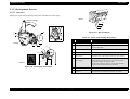
2.1.5.1 Overview
Putting toner on the static latent image on the OPC drum makes the toner image.
0992s24
Toner Cartridge
11
10
7
9
6
1
Figure 2-9. Bias Terminals
2
Table 2-2. Parts of Developing Mechanism
8
4121s032
5
4121s031
3
4
No.
Name
Function
1
Toner hopper
Toner is in.
2
Toner agitation wing
Agitates the toner hopper inside and sends toner to the
toner sending roller.
3
Toner sending roller
Transfers toner to the sleeve roller.
4
Sleeve roller
Rotates the resin sleeve.
5
Resin sleeve
Transfers toner to the surface of the OPC drum surface.
6
Photoconductor
(OPC drum)
Creates the latent image on the surface by the laser beam.
Develops the image by the resin sleeve and carries the
developed image to the paper surface.
Gives toner a negative charge by letting toner through
between the toner blade and the resin sleeve.
7
Toner blade
Puts toner thin and even on the resin sleeve.
8
Bias seal
Collect toner which did not stick to the OPC drum
6
4
7
3
8
9
4110s034
10
11
Figure 2-8. Developing Mechanism
Operating Principles
Operating Principles of Mechanism
52
EPSON EPL-5800
Revision B
Table 2-2. Parts of Developing Mechanism
No.
Name
Function
9
Development blade
voltage terminal (VBL)
DC-590V
10
Development voltage
terminal (VB)
DC-340V
11
Under development seal
terminal (Vss)
DC-340V
Operating Principles
Operating Principles of Mechanism
53
EPSON EPL-5800
Revision B
2.1.6 Transfer Process
OPC Drum
2.1.6.1 Overview
! During the image transfer process the image created on the OPC drum in the
development process is transferred to the paper.
! Transfer method is not the corona transfer but the roller transfer method by the
transfer roller.
! Roller transfer method has low rate of ozone occurrence by corona discharge, and
chances for dislocating the transferred image is very small because the paper
passes between the drum and the transfer roller all through during printing.
Paper
4121s034
Transfer Roller
! The reversed bias is charged on the transfer roller when cleaning the transfer roller
before printing.
! Leftover electric potential on the paper is removed by the discharge needle.
Discharge Needle
Transfer Roll
Reversed Bias
(-1KV)
OPC
Drum
Transfer Bias
(3KV)
Paper
4121s035
Figure 2-10. Transfer Mechanism
Operating Principles
Operating Principles of Mechanism
54
EPSON EPL-5800
Revision B
2.1.7.2 Fusing Temperature Control Circuit
2.1.7 Fusing Process
! The thermistor (TH1) detects the surface temperature of the fusing heat roller and
2.1.7.1 Overview
! In this process, toner which is transferred to the paper in the transfer process is
fused to the paper.
! Fusing system this printer uses is the heat roller fusing system.
The toner passes between the back-up roller and the heat roller, which is heated up
by the heater lamp, and heat and pressure are applied to permanently fuse the toner
to the paper.
inputs the analog voltage to IC1A-78.
Based on the thermistor detected temperature, the heater lamp (H1) is turned ON
(light on) and OFF (light off) by the heater lamp ON/OFF signal which is output
by the IC1A-55, and controls the temperature of the fusing components.
! When the heater lamp is not turned OFF even though the thermistor detects
abnormal high temperature (when the surface temperature of the fusing heat roller
exceeds 210°C), the output from IC-79 is changed from L to H and it forcibly turns
the heater lamp OFF.
PWB-P
Paper
Separating Claw
1
2
TH1
Thermostat
(TS1)
1
2
PJ2
1
2
78 CMPIN/AN8/P63
DC5V
PU1
Back-up Roller
Thermistor
(TH1)
CN1
1 HEAT_N
2 N.C.
3 HEAT_L
H1
GND
GND
+24V
GND
GND
+5V
SLEEP_MODE
CN2
1
2
3
4
5
24V_MON
6
FUSER_LAMP
7
PJ7
1
2
3
4
5
6
7
IC1
L
DT1
IC2
H
3
1
2
L
L
79 CMPOUT
55 P01
TS1
DC5V
Heater Lamp
(H1)
GND
Front Guide Board
4121s037
Heat Roller
4121s036
L H1: ON
H H1: OFF
Figure 2-12. Fusing Temperature Control Circuit
Figure 2-11. Fusing Mechanism
Operating Principles
Operating Principles of Mechanism
55
EPSON EPL-5800
Revision B
AT 600DPI
Temperature detected by
thermistor
When the power switch is turned ON, the printer performs initialization, warm-up starts,
and the heater lamp is turned on. Then, the following temperature controls are performed.
" Temperature control mode 1
This mode controls temperature during printing as 195°C and temperature in
standby as 115°C.
After this mode continues for 90 seconds, it shifts to the mode 2.
" Temperature control mode 2
After this mode continues for 208 seconds, it shifts to the mode 3.
Printing temperature of the fusing roller is gradually lowered from 195°C to
185°C.
Heat Roller Temperature
Warm-up
195°C
185°C
During Printing
(600dpi)
155°C
150°C
During Printing
(1200dpi)
Standby
115°C
" Temperature control mode 3
Controls temperature during printing as 185°C and temperature in standby as
115°C.
Unless any errors generated or open the upper cover, this mode is sustained.
Mode 1: 90sec
Mode 2: 208sec
Mode 3
Figure 2-13. Heat Roller Temperature Control
AT 1200DPI
When the power switch is turned ON, the printer performs initialization, warm-up starts,
and the heater lamp is turned on. The heater lamp stays ON until the temperature of the hear
roller reaches about 155°C. Then, the following temperature controls are performed.
" Temperature control mode 1
Controls temperature during printing as 155°C and temperature in standby as
115°C.
After this mode continues for 45 seconds, it shifts to the mode 2.
" Temperature control mode 2
After this mode continues for 208 seconds, it shifts to the mode 3.
Printing temperature of the fusing roller is gradually lowered from 155°C to
150°C.
Table 2-3. Heat Roller Temperature Control
Temperature just after temperature control started
Condition before
temperature control is
aborted
Less than 50°C
Mode 1, during the warm-up
Mode1
Mode 2, 3, or when the power
supply OFF
Mode 1
50°C or over
less than 115°C
115°C or over
Mode 2
Mode 3
" Temperature control mode 3
Controls temperature during printing as 150°C and in standby as 115°C.
Unless any errors generated or open the upper cover, this mode is sustained.
Operating Principles
Operating Principles of Mechanism
56
EPSON EPL-5800
Revision B
2.1.8 Paper Eject Process
Table 2-4. Capacity of the Trays
Capacity on each tray
2.1.8.1 Face up / Face down Switching Function
After fusing process, paper is ejected either face up or face down by the face up / face down
switching function.
Manual operation of the paper eject switching lever gears the tray switching guide inside
the printer, and the paper path either to the face up eject or to the face down eject is
switched.
The paper eject switching lever is located at the paper eject.
Face down tray
100 sheets
Face up tray
20 sheets
Paper Eject
Switching Lever
Face up Eject
Face-down Eject
Face-up Eject
Roller
Paper Eject
Switching Guide
Pace down Paper
Eject Roller
4121s039
Figure 2-14. Paper Eject Mechanism
FACE DOWN EJECT
Paper is ejected to the face down tray which is located on the top of the printer.
FACE UP EJECT
Paper is ejected to the optional face up tray.
Face up eject is available even without optional face up tray.
Operating Principles
Operating Principles of Mechanism
57
CHAPTER
3
TROUBLESHOOTING
EPSON EPL-5800
Revision B
3.1 Troubleshooting
5.
The paper feed sensor (PS1) is ON when the power ON/OFF switch (S1) is ON or
when the cover is closed.
This section describes the basic procedure for checking the printer operation that allows you
to find out troubles and necessary repair service easily.
6.
The paper eject sensor (PS3) is ON when the power ON/OFF switch (S1) is ON or
when the top cover is closed.
3.1.1 Troubleshooting for Paper Jam
RESETTING THE PAPER JAM
The printer checks if there is paper in the printer or not by detecting the signals from the
paper feed sensor (PS1) and the paper eject sensor (PS3).
Paper jam during paper passing is detected by rise and fall of signals from PS1 and PS3.
When paper jam is detected, all the drive is turned OFF (except for the following cases).
After the paper jam is cleared, the error is canceled by closing the top cover.
! Continuous Printing
When detecting case 1 in "Paper Jam Conditions", and if there is carrying paper in
the printer, the printer turns all the drive OFF after ejecting the carrying paper.
! Single Printing
When detecting only case 1 in "Paper Jam Conditions", since there is no paper in
the fusing unit, the printer does not turn the heater lamp (H1) OFF, but turns the
other drive OFF.
PAPER JAM CONDITIONS
1.
The paper feed sensor (PS1) is not turned ON
- within about 2.1 seconds (at 1200dpi: within about 13.58 sec) after the multi paper
feed tray starts feeding paper (in other words, the paper feed roller starts rotating by
turning the paper feed solenoid ON).
- within about 2.35 seconds (at 1200dpi: within about 4.7 sec) after the second paper
feed unit starts feeding paper.
2.
The paper feed sensor (PS1) is not turned OFF within about 6.79 seconds (at 1200dpi:
within about 13.58 sec) after the top edge of paper reaches the paper feed sensor (PS1)
(PS1:ON).
3.
The paper eject sensor (PS 3) is not turned ON within about 2.3~3.08 seconds (at
1200dpi: within about 4.6~6.16 sec) after the top edge of paper reaches the paper feed
sensor (PS1) (PS1:ON).
4.
The paper eject sensor (PS 3) is not turned OFF within about 2.05~2.82 seconds (at
1200dpi: within about 4.1~5.64 sec) after the bottom edge of paper passes by the paper
feed sensor (PS1) (PS1:OFF).
Troubleshooting
Troubleshooting
59
EPSON EPL-5800
Revision B
3.1.1.1 Check Point
Table 3-2. Troubleshooting for the Paper Jam (2)
The table below lists the check-point for identifying possible cause of paper jam occured
with different timing.
PAPER JAM WHEN THE POWER IS ON
Check Item
Remedy
Is the paper feed roller deformed?
Or is it worn out by friction or is there any
dirt?
Replace the paper feed roller.
Replace the second paper feed roller.
→
Yes
↓No
Table 3-1. Troubleshooting for the Paper Jam (1)
Check Item
Does the lever of the paper feed sensor
(PS1) operate normally?
Remedy
Is there any paper left?
↓No
Does the lever of the paper eject sensor
(PS3) operate normally?
↓Yes
Does the lever of the paper feed sensor
(PS1)and the second paper feed sensor
(PS21) work right?
→
Yes
→
No
Remove all the paper in the printer.
Check the lever operation.
Check the lever operation.
Check Item
Remedy
Replace PS1 or PS21.
Replace PS3.
Replace the main control board.
Is the transfer roller deformed?
Or is it worn out by friction or is there any
dirt?
(the life end of the transfer roller)
Replace the Transfer roller.
→
Yes
Is the fusing roller deformed?
Or is it worn out by friction or is there any
dirt?
Do the paper feed roller and the second
paper feed roller rotate?
→
No
Replace the paper feed solenoid (SL1).
Replace the second paper feed solenoid
(SL21).
→
No
Ask the user to use the recommended
paper.
→
Yes
Replace the paper and tell the user how
to keep paper.
↓No
Troubleshooting
→
Yes
↓No
Remedy
Is paper bent, wrinkle, or wet?
Replace PS1.
Replace the main control board.
→
No
Check Item
↓Yes
→
Yes
Table 3-3. Troubleshooting for the Paper Jam (3)
Table 3-2. Troubleshooting for the Paper Jam (2)
Is recommended paper used?
Check the lever operation.
PAPER JAM FROM THE TRANSPORT TO THE PAPER EJECT
PAPER JAM FROM THE PAPER FEED TO THE TRANSPORT
↓Yes
→
No
Replace the fusing unit.
→
Yes
↓No
Does the paper eject roller rotate?
↓Yes
Does the lever of the paper eject sensor
(PS3) operate normally?
Troubleshooting
→
No
Replace the top cover assembly.
→
No
Check the lever operation.
→
Yes
Replace the fusing unit or PS3.
Replace the main control board.
60
EPSON EPL-5800
Revision B
3.1.2 Troubleshooting for Abnormal Operations
ABNORMAL FAN MOTOR
If the following errors are detected by a built-in diagnostic function, all the drive is turned
OFF and the hardware error is indicated on the control panel.
This error is detected in the following case;
1.
ABNORMAL LASER
1.
Right after the polygon motor starts rotating, the laser diode is forced to emit lights and
the laser power is adjusted.
While the laser power adjusted, if the adjustment signal (DA1, DA2) goes out of rated
value, it is detected as abnormal laser.
ABNORMAL POLYGON MOTOR
Motor lock signal is detected as “H” for 2.0 sec continuously after the fan motor is
turned ON. (At normal rotation, the motor lock signal indicates “L”)
ABNORMAL FUSING
1.
If in any condition the thermistor detects that the temperature exceeds 220°C for
50msec, it determines as fusing abnormal high temperature.
2.
The temperature detected by the thermistor from 8 to 12 seconds after warming-up and
the temperature detected by the thermistor when warming-up starts are compared, and
if it is detected that the temperature detected by the thermistor is below the standard
value for 50msec, it determines the thermistor is in trouble.
(This detection applies only when the temperature detected by the thermistor is below
80°C.
This error is detected in the following cases;
1.
/SSCAN signal is not detected even once within 0.8 seconds after the polygon motor is
turned ON.
2.
The rotation number of polygon motor does not settle within ±0.5% within 6.0 seconds
after the polygon motor is turned ON.
3.
If the temperature detected by the thermistor does not reach the setting temperature
within 45 seconds after warming-up starts, it determines as fusing abnormal rising.
3.
After the polygon motor is turned ON and the rotation number of polygon motor
settled within ±0.5%, the rotation number goes beyond ±3% for more than 5.5 seconds
continuously.
4.
When controlling the temperature, if the temperature detected by the thermistor goes
below the setting temperature for 50msec continuously, it determines as fusing
abnormal low temperature.
Setting temperature is 140°C (600dpi) or 110°C (1200dpi) on the printing mode and
70°C on the waiting mode.
ABNORMAL MAIN MOTOR
This error is detected in the following cases;
1.
Motor lock signal is not detected within 1.0sec after the main motor is turned ON.
2.
Motor lock signal is turned OFF for 0.1 sec continuously.
Troubleshooting
Troubleshooting
61
EPSON EPL-5800
Revision B
3.1.2.1 Check Point
ABNORMAL FUSING
The table below lists the check-point for identifying the possible cause and a remedy for
each error detected by the printer.
Table 3-8. Troubleshooting for the Abnormal Fusing
Check Item
ABNORMAL LASER
Remedy
Is the fusing unit warmed-up?
↓No
→
Yes
Replace the thermistor (TH1) or the
fusing unit.
Replace the main control board.
Replace the power unit (PU1).
Is there continuity between Pin 1 and Pin 3
of the connector of the fusing unit?
→
No
Replace the fusing unit.
Replace the heater lamp (H1) or the
thermostat (TS1).
→
Yes
Replace the power unit (PU1) or the
main control board.
Table 3-4. Troubleshooting for Abnormal Laser
Cause
Remedy
Abnormal laser diode
Replace the print head unit.
Replace the main control board.
ABNORMAL POLYGON MOTOR
Table 3-5. Troubleshooting for Abnormal Polygon Motor
Cause
Remedy
Abnormal Polygon Motor
Replace the print head unit.
Replace the main control board.
ABNORMAL MAIN MOTOR
POWER CANNOT BE TURNED ON
Table 3-9. Power Cannot be Turned ON
Check Item
Remedy
Is the power code plugged in?
↓Yes
Table 3-6. Troubleshooting for Abnormal Main Motor
Check Item
Remedy
Main Motor (M1) does not
rotate.
Replace the main motor (M1).
Replace the main control board.
Is the power code connected to the printer
body?
↓Yes
Is the power switch (S1) ON?
↓Yes
→
No
Adjust the position of the interlock
switch (S2).
Is the fuse (F1 or F2) in the power unit PU1)
disconnected?
→
No
Replace the PU1 or the main control
board.
→
Yes
Replace the fuse (F1 or F2).
↓Yes
Is the interlock switch (S2) ON?
Cooling Fan Motor (M2) does
not rotate.
Replace the cooling fan motor (M2).
Replace the main control board.
Troubleshooting
Connect the power code to the printer.
Turn the power switch ON.
Table 3-7. Troubleshooting for Abnormal Fan Motor
Remedy
→
No
Connect the power code to the plug.
→
No
ABNORMAL FAN MOTOR
Check Item
→
No
Troubleshooting
62
EPSON EPL-5800
Revision B
3.1.3 Troubleshooting for Print Quality Problems
Table 3-11. Print Quality Problems 2
When the print quality problems occur, replace the toner cartridge and the drum cartridge
first, and determine either it is caused by each cartridge or caused by the printer.
Symptom
All White
When it is a print quality problem, measure the generating pitch for abnormal images, and
specify the abnormal part with the table below.
Abnormal
Image
Pitch (mm)
Install the toner cartridge.
No toner in the toner
cartridge.
Replace the toner cartridge.
No drum cartridge.
Install the drum cartridge
Defective OPC drum.
Replace the OPC drum.
Abnormal laser emission.
Replace the print head.
Replace the high voltage unit (HV1).
Replace the main control board.
Improper transfer.
Replace the transfer roller.
Replace the high voltage unit (HV1).
Replace the main control board.
Abnormal laser emission.
Replace the print head.
Replace the main control board.
Abnormal charging.
Replace the high voltage unit (HV1).
Replace the main control board.
Paper is wet.
Replace paper.
Improper transfer.
Replace the transfer roller.
Replace the high voltage unit (HV1).
Replace the main control board.
Table 3-10. Print Quality Problems 1
Pitch
Possible Abnormal Part (Diameter)
Solution
No toner cartridge.
0951o211
All Black
Figure 3-1. Print Image
Possible Cause
Replacement Unit
28mm
Sleeve Roller (φ15.7mm)
Toner Cartridge
94.2mm
OPC Drum (φ 30mm)
Drum Cartridge
50.3mm
Transfer Roller (φ 16mm)
Transfer Roller
62.8mm
Heat Roller (φ 20mm)
67.8mm
Backup Roller (φ 21.6mm)
0951o213
White Out
Fusing Unit
0951o220
Troubleshooting
Troubleshooting
63
EPSON EPL-5800
Revision B
Table 3-11. Print Quality Problems 2
Symptom
Back of paper gets
dirty.
Possible Cause
Table 3-11. Print Quality Problems 2
Solution
Symptom
Fusing roller is dirty
Replace the fusing unit (fusing roller).
Transfer roller is dirty.
Replace the transfer roller.
Paper path is dirty.
Clean the paper path.
0951o226
Low image density.
Solution
There is scar or damage on
the OPC drum.
Replace the OPC drum.
Defective print head.
Replace the print head.
Replace the main control board.
Defective fusing roller.
Replace the fusing unit (fusing roller).
Defective transfer roller.
Replace the transfer roller.
0951o222
Offset image.
No toner in the toner
cartridge.
Replace the toner cartridge.
OPC drum is at the end of
life.
Replace the drum cartridge.
Defective developing bias.
Replace the high voltage unit (HV1).
Replace the main control board.
0951o214
Foggy background.
White line. Black
line.
Possible Cause
0951o219
Defective developing bias.
Replace the high voltage unit (HV1).
Replace the main control board.
OPC drum is at the end of
life.
Replace the drum cartridge.
0951o218
Troubleshooting
Troubleshooting
64
CHAPTER
4
DISASSEMBLY AND ASSEMBLY
EPSON EPL-5800
Revision B
4.1 Overview
4.1.1.2 Precaution at Handling the Laser Mechanism
W A R N IN G
4.1.1 Precaution for Disassembly and Assembly
dangerous. Be careful to handle these tools especially at the
user’s place.
! If you cannot turn off the power supply because the service
requires power, remove watches and rings and wear laser
protective goggles.
Use goggles that meet the following specification.
Maximum power: 0.6mW
Output wavelength: 770-810nm
4.1.1.1 Precaution at Maintenance and Disassembling
! Be sure to plug off the power cable before disassembling.
! Unless specially mentioned, reverse the disassembling procedure
!
!
!
!
!
!
for assembling procedure.
If you need to drive the machine with the cover off, be careful not
to pinch hands or clothes in the operating or rotating parts
(gears, rollers, motors, etc.).
Never touch any terminals of electric components or high voltage
components (power supply unit, high voltage unit, etc.).
Do not touch the fusing unit right after turning the printer off,
since the unit remains hot for a while after turning the power
OFF. Disassemble after the fusing unit is enough cooled.
When inserting or removing connectors, make sure the power
supply is OFF. When electricity is turned on, do not remove any
connectors.
When inserting or removing a connectors, be sure to do so
holding the connector housing.
Never insert or remove connectors holding the wiring cord; it
may result in a loose connection.
Use the specified rated fuses.
In order to ensure the electric conduction, install the earth wire
and the earth plate correctly and firmly.
After removing the out-teethed washers, make sure to re-install
them. Do not replace them with other kind of screws or washers.
Disassembly and Assembly
laser path around the print head or around the OPC drum.
! Putting the highly reflective tools into the laser path is
Read following caution and warning carefully before starting disassembly and assembly.
W A R N IN G
! Be sure to disconnect the power supply when working on the
4.1.1.3 Handling Forbidden
C A U T IO N
Never remove, disassemble, nor adjust the following parts.
! Print head unit
! Any parts where the installing screws painted red
4.1.1.4 Precaution at Handling the Print Board
Handling the print board needs the following precautions.
PRECAUTION AT TRANSPORTING AND KEEPING
Overview
C A U T IO N
! For transporting and keeping, keep the printer in the conductive
case or the conductive mat, and do not take off unless necessary.
(Do not use vinyl sack or paper to pack the printer.)
! Avoid direct sunlight when keeping the printer.
! Do not put the printer on places easily charged with static
electricity (on a carpet, etc.) or products (plastic, vinyl sack, etc.).
66
EPSON EPL-5800
Revision B
PRECAUTION AT REPLACING
C A U T IO N
PRECAUTION AT HANDLING
! Basic replacement = unit or assembly replacement
! When removing connectors from the print board, be sure to
C A U T IO N
unplug the power supply in advance.
! When taking the print board out of the conductive sack or
conductive case, or when replacing the print board, be sure to
handle it with the edge of the board and avoid touching IC
terminals and patterns.
! The OPC Drum is very sensitive to light and the recovery of
sensitivity takes time; do not open the protection cover or do not
expose to the sunlight for a long period.
! Do not put fingerprints, oil, or chemicals on the surface of the
OPC Drum.
! Do not scratch the surface of OPC Drum.
PRECAUTION AT CHECKING
C A U T IO N
! Avoid direct IC check by the tester. Determine OK/NG by
checking the connector on the board.
! Be sure to avoid any short between IC terminals caused by
metallic tools.
! If touching the elements on the board is unavoidable, be sure to
perform body earth.
4.1.1.5 Precaution at Handling the Photoconductor (Drum
Cartridge)
PRECAUTION AT TRANSPORTING AND KEEPING
C A U T IO N
! For transporting and keeping, be sure to use specified boxes.
! When keeping the printer, avoid direct sunlight and keep
temperature between -20°C ~40°C.
Disassembly and Assembly
Overview
67
EPSON EPL-5800
Revision B
.
4.1.2 Regularly Replacement Parts
Humidity(%)
85
Table 4-1. Regularly Replacement Parts
Parts Name
Cleaning
Cycle
Replacement Cycle
(Continuous Printing)
Replacement Cycle
(Intermittent Printing)
Drum Cartridge
None
About 20,000 sheets
About 16,000 sheets
Toner Cartridge
(Supplied by a
consumer)
None
About 6,000 sheets
About 4,800 sheets
Toner Cartridge
(Packaged)
None
About 3,000 sheets
About 2,400 sheets
Transfer Roller
(A and C
environment in the
Figure 4-1)
None
About 135,000 sheets
About 80,000 sheets
Transfer Roller
(B environment in
the Figure 4-1)
None
Fusing Unit
None
About 50,000 sheets
Paper feed roller
When paper
feed trouble is
happened.
Replace when trouble is happened.
Second paper feed
unit
paper feed roller
C
70
65
A
35
B
15
0
10 15
25 30 35
Temperature(°C)
4121s081
Figure 4-1. Temperature and Humidity Environment
4.1.3 Service Tools
About 100,000 sheets
Table 4-2. Tools
About 50,000 sheets
+ Driver (No.1)
+ Driver (No. 2)
+ Mini Driver
- Driver
4.1.4 Specification for Screws
Table 4-3. Screws
Figure
NOTE: Drum cartridge and toner cartridge are basically to be replaced by users.
DxL
Figure
DxL
3x6
3x8
3x6
3x8
3x6
3x8
Figure
DxL
3x8
Note)D x L = Diameter x Length (mm)
Disassembly and Assembly
Overview
68
EPSON EPL-5800
Revision B
4.2 Disassembly Procedure
Second Paper Feed Unit
The flowchart below is disassembly procedure for EPSON EPL-5800.
Second Paper Feed Roller
4.2.4
4.2.1
4.2.20
Paper Empty Sensor (PE1)
Open the Top Cover
Toner Cartridge
Drum Cartridge
Relay Board (PWB-A)
4.2.4
4.2.22
Paper Feed Roller Cover
Cassette Type Detection Switch (SW21)
4.2.5
Right Cover
4.2.23
4.2.3
4.2.2
Paper Feed Roller
Front Cover Transferring
4.2.6
Transfer Roller
Control Panel
4.2.3
Second Paper Feed Solenoid (SL21)
4.2.24
Figure 4-3. Disassembly Flowchart 2
4.2.8
Main Control Board
Left Cover
4.2.8
Front Cover
4.2.7
4.2.9
4.2.9
Paper Feed Unit
Paper Feed Solenoid (SL1)
4.2.11
Interlock Switch (S2)
Top Cover
4.2.16
4.2.11
Print Head Unit (PH)
Rear Cover
4.2.17
4.2.12
Cooling Fan Motor
4.2.13
Main Motor Assembly
4.2.15
4.2.14
Backup Roller
Heater Lamp (H1)
Heat Roller
Thermostat (TS1)
Thermistor (TH1)
Fusing Separation Claw
Fusing Unit
4.2.18
Power Supply Unit (PU1)
Paper Feed Sensor (PS1)
High Voltage Unit (HV1)
4.2.18
4.2.19
Figure 4-2. Disassembly Flowchart 1
Disassembly and Assembly
Disassembly Procedure
69
EPSON EPL-5800
Revision B
4.2.1 Preparation before disassembling
4.2.2 Paper Feed Roller Replacement
Before disassembling the printer, removal of the minimum units are necessary.
1.
Open the paper feed roller cover and remove the paper feed roller. (one screw)
NOTE: When installing the paper feed roller, tighten the screw after making sure
the pin on the back of the roller goes in the shaft hole.
Drum Cartridge
Toner Cartridge
Paper Feed Roller Cover
1308
Top Cover
4121s041
4121s042
Figure 4-4. Removal of Minimum Units
1.
Press the top cover release button, and open the top cover as full open.
2.
Take out the toner cartridge.
3.
Take out the drum cartridge.
Disassembly and Assembly
Figure 4-5. Paper Feed Roller Replacement
Disassembly Procedure
70
EPSON EPL-5800
Revision B
4.2.3 Transfer Roller Replacement
Replace the transfer roller every about 50,000 sheets.
C A U T IO N
3.
Remove the right and left shaft supports and gear from the removed transfer roller, and
install them to the new transfer roller.
4.
Insert the transfer roller to the transfer roller holder of the printer, and set the bearing
lever to the top.
! Since the life span of the transfer roller and fusing unit are the
same, if you need to replace the transfer roller because of wornout etc., make sure to replace the fusing unit as well.
! Do not touch the surface of the transfer roller nor stain it with
chemicals or toner, for the dents or dirt on the surface of the
transfer roller badly affects on the printing quality.
! When handling the transfer roller, hold the shaft of the roller or
the shaft supports.
1.
Use the mini driver and remove the transfer front cover. (two screws)
2.
Push down the lever of the shaft supports (white) on the right and left of the transfer
roller toward the front, and remove the transfer roller from the transfer roller holder.
Transfer Roller Holder
4121s044
4121s044b
Figure 4-7. Installing the Transfer Roller
Transfer Roller Holder
5.
Install the transfer front cover. (two screws)
3907
Transfer Roller
Front Cover Transferring
4121s043
3907
Figure 4-6. Transfer Roller Removal
Disassembly and Assembly
Disassembly Procedure
71
EPSON EPL-5800
Revision B
4.2.4 Paper Empty Sensor (PE1) Removal
4.2.5 Right Cover Removal
1.
Remove paper feed roller cover.
1.
2.
Remove the paper empty sensor (PE1) and pull out the connector.
NOTE: When installing the right cover, insert two hooks at the bottom of the
right cover to the frame.
Remove the right cover. (two screws, two hooks)
Paper Feed
Roller Cover
Paper Empty Sensor
4121s073
Figure 4-8. Paper Empty Sensor (PE1) Removal
4121s045
Figure 4-9. Right Cover Removal
Disassembly and Assembly
Disassembly Procedure
72
EPSON EPL-5800
Revision B
4.2.6 Control Panel Removal
4.2.7 Main Control Board (PWB-P) Removal
1.
1.
Remove the control panel. (two screws)
Remove all connectors on the main control board (PWB-P) (twelve connectors) and
remover the main control board (PWB-P). (ten screws)
3501
4121s084
Figure 4-10. Control Panel Removal
4121s046
Figure 4-11. Main Control Board (PWB-P) Removal
Disassembly and Assembly
Disassembly Procedure
73
EPSON EPL-5800
Revision B
4.2.8 Left Cover and Front Cover Removal
4.2.9 Paper Feed Solenoid (SL1) Removal
1.
Remove the left cover. (two screws, two hooks)
1.
Remove the right cover, the left cover, and the front cover.
2.
After removing the right cover, remove the front cover. (four screws)
2.
Close the top cover and turn it down 90° to the back.
NOTE: Do not catch the paper empty sensor when removing the front cover.
When installing the left cover, insert the hooks at the bottom of the cover
to the frame.
Left Cover
Front Cover
3504
4121s049
Figure 4-13. Paper Feed Solenoid (SL1) Removal 1
Paper Empty
Sensor
4121s047
Figure 4-12. Left Cover and Front Cover Removal
Disassembly and Assembly
Disassembly Procedure
74
EPSON EPL-5800
Revision B
3.
Remove the paper feed unit. (five screws, one connector)
4.2.10 Top Cover Removal
4.
Remove the paper feed solenoid (SL1). (one screw)
1.
Remove the right cover and the left cover.
2.
Remove the top cover. (two hooks)
Paper Feed Unit
4121s050
Paper Feed
Solenoid
Top View
4121s051
4121s074
When installing the unit,
make sure that the screw-in
part of the unit goes in the
left resinous frame.
Figure 4-15. Top Cover Removal
4121s075
When removing the solenoid, pull the right side
of the paper feed unit endways and remove it
while shifting the whole unit to the right.
Figure 4-14. Paper Feed Solenoid (SL1) Removal 2
Disassembly and Assembly
Disassembly Procedure
75
EPSON EPL-5800
Revision B
4.2.11 Rear Cover Removal
4.2.12 Cooling Fan Removal
1.
Remove the rear cover. (six screws, one connector)
1.
Remove the rear cover.
2.
Remove the top cover. (two hooks)
2.
Remove the cooling fan. (three screws)
3704
3501
3704
3501
3704
3501
4109s52
3501
3501
1112
4109s53
Figure 4-17. Cooling Fan Removal
Figure 4-16. Rear Cover Removal
Disassembly and Assembly
Disassembly Procedure
76
EPSON EPL-5800
Revision B
4.2.13 Main Motor Assembly Removal
4.2.14 Fusing Unit Removal
1.
Remove the rear cover.
Replace the fusing unit by unit basically every about 50,000 sheets.
2.
Remove the main motor assembly. (three screws, one connector)
C A U T IO N
The life span of the transfer roller and fusing unit are the same. So, if
you need to replace the fusing unit because of worn-out etc., make sure
to replace the transfer roller as well.
1.
Remove the right cover, the left cover, and the rear cover.
2.
Remove the fusing unit. (three screws, three connectors)
3504
3504
4121s054
Figure 4-18. Main Motor Assembly Removal
3704
4109s56
Figure 4-19. Fusing Unit Removal
NOTE: If you need to disassemble the fusing unit because of image quality
problems and defective components, follow the instruction in “Fusing
Unit Disassembly” on page 78.
Disassembly and Assembly
Disassembly Procedure
77
EPSON EPL-5800
Revision B
4.2.15 Fusing Unit Disassembly
3.
Remove the backup roller.
1.
Remove two installation screws.
4.
Remove the fixation front guide board.
2.
Press the left and right hooks (two hooks each) and separate the fixation unit.
(1) Shift the fixation front guide board to the left.
(2) Remove the right side of the fixation front guide.
3704
(3) Remove the left side of the fixation front guide.
Backup Roller
(1)
(3)
4121s057
Figure 4-20. Fusing Unit Disassembly
(2)
Front Fusing
Guide
4121s058
Figure 4-21. Backup Roller and Front Fusing Guide Removal
Disassembly and Assembly
Disassembly Procedure
78
EPSON EPL-5800
Revision B
5.
Remove the terminal board. (two screws)
7.
Remove the driven gear from the heat roller.
6.
Pull out the heater lamp.
8.
Shift the heat roller to the right side (1) and then shift it to (2) direction, and pull the
roller out toward (3) direction.
C A U T IO N
! Do not touch the glass of the lamp with bare hands.
! When installing the heater lamp, install it as the voltage indicator
faces the gear side.
C A U T IO N
To avoid scratching the heat roller surface by the fusing separation
claw, when removing or installing the roller, keep the fusing
separation claw lifted untouched.
(2)
1305
Heater Lamp
3704
(3)
(1)
Voltage Indicator
4121s059
Figure 4-22. Heater Lamp Removal
4121s060
Figure 4-23. Drive Gear Removal
Disassembly and Assembly
Disassembly Procedure
79
EPSON EPL-5800
9.
Revision B
Remove the roller assembly. (two screws)
4.2.16 Interlock Switch (S2) Removal
10. Remove the fusing separation claws. (four claws)
1.
Remove the right cover, the left cover, and the rear cover.
11. Remove the thermistor (TH1). (one screw)
2.
Remove the interlock switch (S2). (one screw, two connectors)
NOTE: When installing the thermistor, let the harness through as shown in the
figure 1 of the Figure 4-24.
Interlock
Switch
12. Remove the thermostat (TS1). (two screws)
3704
Roller Assy.
Thermostat
Thermistor
4121s062
Roller Assy.
Red
Orange
Figure 4-25. Interlock Switch (S2) Removal
Fusing Separate Claw (4)
4121s061
Figure 1 Back of the Fusing Unit
Harness
4121s077
Figure 4-24. Thermistor and Thermostat Removal
Disassembly and Assembly
Disassembly Procedure
80
EPSON EPL-5800
Revision B
4.2.17 Print Head Unit (PH) Removal
4.2.18 Power Unit (PU1), Paper Feed Sensor (PS1)
Removal
1.
Remove the right cover, the left cover, and the rear cover.
2.
Pull out the connectors (PJ5, PJ9, PJ12) from the main control board and remove the
wires from the cold holder.
1.
Remove the right cover, the left cover, and the front cover.
2.
Pull out PJ7 from the main control board and remove the harness from the cold holder.
Remove the print head (PH). (seven screws)
3.
Remove the power supply unit (PU1). (four screws, two connectors)
3.
NOTE: When installing the print head (PH1), install it with the shutter open.
3704
3501
3501
3704
3501
3501
3501
3504
1305
4121s63
3501
Cold Holder
4121s064
Figure 4-26. Print Head Unit (PH) Removal
Disassembly and Assembly
3501
Figure 4-27. Power Unit (PU1) Removal
Disassembly Procedure
81
EPSON EPL-5800
4.
Revision B
Remove the paper feed sensor (PS1). (one connector)
4.2.19 High Voltage Unit (HV1) Removal
1.
Remove the right cover, the left cover, and the rear cover.
2.
Remove the power supply unit.
3.
Remove the high voltage unit (HV1). (three screws, one connector)
NOTE: When installing the high voltage unit (HV1), be careful at the following
points.
!Install the earth plate at the rear of the high voltage unit as shown in the
Figure 1 in the Figure 4-29.
!Make sure all the contact points (four points) are contacted.
4121s078
4121s065
Figure 1
Figure 4-28. Paper Feed Sensor (PS1) Removal
Earth
Plate
4121s079
Contacting
Points
4121s066
Figure 4-29. High Voltage Unit (HV1) Removal
Disassembly and Assembly
Disassembly Procedure
82
EPSON EPL-5800
Revision B
4.2.20 Second Paper Feed Roller Replacement
4.2.21 Second Paper Feed Unit Removal
1.
Separate the second paper feed unit from the printer.
1.
Remove the black cover. (one screw, two picks)
2.
Remove the paper feed roller as shown in the figure 1 in the Figure 4-30.
2.
Remove the actuator.
1) Lift the tab of the paper feed roller.
Actuator
2) Shift the paper feed roller to the right.
3704
3) Remove the paper feed roller.
3.
Install a new paper feed roller by reversing the procedure of step 2.
Paper Feed Roller
4121s068
Figure 4-31. Actuator Removal
Figure 1
(3)
4121s067
(1) (2)
4121s080
Figure 4-30. Second Paper Feed Roller Replacement
Disassembly and Assembly
Disassembly Procedure
83
EPSON EPL-5800
3.
Revision B
Remove the second paper feed unit.
3704
4.2.22 Relay Board (PWB-A) Removal
3704
3704
1.
Remove the cover. (one screw, two connectors)
2.
Remove the relay board (PWB-A). (two screws)
3704
Relay Board
3704
3501
3501
4121s070
4121s069
3504
Figure 4-33. Relay Board (PWB-A) Removal
Figure 4-32. Paper Feed Unit Removal
Disassembly and Assembly
Disassembly Procedure
84
EPSON EPL-5800
Revision B
4.2.23 Second Paper Size Detection Switch (SW21)
Removal
4.2.24 Second Paper Feed Solenoid (SL21) Removal
1.
Remove the cover. (one screw)
1.
2.
Remove the harness from the wire saddle and remove the second paper feed solenoid
(SL21). (one screw, one connector)
Remove the second paper size detect switch (SW21).
Second Paper
Feed Solenoid
4121s071
Wire Saddle
Figure 4-34. Second Paper Size Detection Switch (SW21) Removal
4121s072
3501
Figure 4-35. Second Paper Feed Solenoid (SL21) Removal
Disassembly and Assembly
Disassembly Procedure
85
CHAPTER
5
ADJUSTMENT
EPSON EPL 5800
Revision B
5.1 Adjustment
ADJUSTMENT BY VOLTAGE CHANGE
This chapter explains adjustment procedure. Adjustment should be done after components
and parts are replaced.
1.
With the power ON, put + terminal of the tester on VR1 and - terminal on the frame
GND.
2.
Adjust the position as the tester value becomes DC2.5 ± 0.1V.
5.1.1 Print Start Position Adjustment
After replacing the main control board, make sure the sub scanning start position (d) is
4mm from the top edge of paper.
If the sub scanning start position (d) is not 4mm from the top edge of paper, adjust the
position by following the instruction below.
C A U T IO N
Print start position adjustment should basically be performed with the
procedure “Adjustment by Actual Printing”.
ADJUSTMENT BY ACTUAL PRINTING
1.
Remove the right cover, and prepare VR1 on the main control board ready for
adjustment.
2.
If you rotate VR1 on the main control board clockwise, d gets larger.
If you rotate VR1 on the main control board counterclockwise, d gets smaller.
PJ5(8P)
PJ3(2P)
d
VR1
PJ9(5P)
PJ1(30P)
PJ8(3P)
PJ2(2P)
PJ7(7P)
PJ4(11P)
PJ6(5P)
PJ13(4P)
PJ10(2P)
PJ11(12P)
PJ12(4P)
Figure 5-1. Print Start Position Adjustment
Adjustment
Adjustment
87
EPSON EPL 5800
Revision B
5.1.2 Interlock Switch Position Adjustment
With the power ON, if the printer does not become ON when the top cover is closed,
perform the position adjustment of interlock switch (S2) by the following procedure.
1.
Open the top cover, and remove the left cover, the right cover and the front cover.
2.
Loosen the screw fixing interlock switch (S2), and close the top cover completely.
3.
Move the interlock switch (S2) up and down, and tighten the screw where the switch
turns ON.
S2
4121s082
Figure 5-2. Interlock Switch Position Adjustment
Adjustment
Adjustment
88
EPSON EPL 5800
Revision B
5.1.3 USB ID Input
PROGRAM OPERATION
EPL-5800 comes with the USB interface as a standard, and the PC connected to the EPL5800 via the USB interface identifies the printer by referring to the USB ID information
unique to each printer. Since this USB ID information is stored on EEPROM on the main
controller board of the printer, you have to re-define the ID information when you need to
replace the main board for repair.
C A U T IO N
1.
When you execute the program, the following menu window will appear.
When you repair the printer and re-define the USB ID information,
you have to notify it to the user to uninstall a previously installed
printer driver as it is referring to an old USB ID information.
The program for USB ID input and a supported operating environment is as follows.
! Program
EPL5800.EXE
! Operating environment
" Supported OS:
Windows 95/98
2.
Select the printer. (Only one printer: EPL-5800 is listed.)
" Supported I/F:
Parallel I/F
3.
If you need to input new USB ID information to the printer, clcik “USB ID Input”
radio button and click “OK” to proceed.
PROGRAM SETUP
1.
Insert the supplied program diskette labeled as “Disk-1” into a floppy disk drive on the
PC, and execute the program “SETUP.EXE”.
2.
Follow the setup instruction displayed on the PC. (replace the floppy disk to “Disk-2”
when you are instructed to do so by the setup program.)
3.
When the setup is completed, you can start the program by selecting it from the
Program menu.
Adjustment
Adjustment
89
EPSON EPL 5800
4.
Revision B
When the following window appear, input the serial number of the printer and click
“Ok” button to store the USB ID information to an EEPROM on the main board of the
printer. Take a note of the USB ID value displayed in the status window of the
program, and this should be referred to when you check the inputted USB ID later on.
USB ID CONFIRMATION
When you re-define the USB ID, make sure to verify it with the following procedure.
C A U T IO N
C H E C K
P O IN T
Adjustment
Make sure to set a paper in the printer before selecting this function,
as the program execute the status sheet print operation for checking
input USB-ID.
1.
After executing the program and selecting the printer, click on “Verify USB ID” radio
button.
2.
When you clicking on “OK” button, the program prints the status sheet . Then, confirm
that the USB ID value printed on the status sheet is the same as the one you have
confirmed when you input it.
USB ID is 18-digit value and the program automatically generates a
rest of ID based on the serial number inputted by the operator.
Adjustment
90
CHAPTER
6
MAINTENANCE
EPSON EPL-5800
Revision B
6.1 Maintenance
6.1.2 Maintenance of Consumables
This section gives information neccesary for maintaining the printer in its optimum
condition. Preriodical user maintenance and service maintenance are necesssary in order to
maintain the high printing quality.
6.1.1 User Maintenance on Main Unit
A user is responsible for the maintenance of all consumables.
Table 6-2. Maintenance of Consumables
Maintenance Item
Clean paper-feed
roller
Maintenance
Timing
Method
When a paper feeding
problem occurs.
1. Open the top cover and remove
Developer Cartridge and
photoconductor unit.
2. Open the paper-feed roller cover and
wipe the roller with a damp, soft cloth.
Do not use a solvent such as alcohol.
Method
Developer cartridge
Replace after
printing approx.
6,000 sheets
Follow the procedure below to replace the
Developer cartridge.
1. Press the open button and open the top
cover.
2. Grasp the handles on the Developer
cartridge and pull off the cartridge from the
unit.
3. Hold the new Developer cartridge and
shake it from side to side.
4. Fully insert the new Developer cartridge
into the printer.
5. Close the top cover.
Photoconductor unit
Replace after
printing approx.
20,000 sheets
Follow the procedure below to replace the
photoconductor unit.
1. Press the open button and open the top
cover.
2. Grasp the handles on the Developer
cartridge and pull off the cartridge from the
unit.
3. Pull off the photoconductor unit.
4. Fully insert the new Photoconductor unit
into the printer.
5. Insert the Developer Cartridge which
removed at (2) above.
6. Close the top cover.
Table 6-1. User Maintenance on Main Unit
Maintenance Item
Timing
Maintenance
92
EPSON EPL-5800
Revision B
6.1.3 Maintenance by Service Technicians
The following maintenance must be undertaken by a qualified service technician.
Table 6-3. User Maintenance by Service Technicians
Maintenance Item
Timing
Transfer roller.
Clean when a problem occurs.
Replace after printing 50,000 sheets.
Fusing unit
Clean when a problem occurs.
Replace after printing 50,000 sheets.
Maintenance
Maintenance
93
CHAPTER
7
APPENDIX
EPSON EPL-5800
7.1 Overview
Revision B
7.2.2 Connector List
Table 7-1. Connector List
This section provides the supplementally informaiton for servicing the EPL-5800.
Connector
7.2 Connectors
Pin #
Table
C361MAIN BOARD
7.2.1 Connection diagrams
The figure below shows the conneciton between the C361MAIN board and the other
electrical circuitries and the printer engine mechanism.
Figure 7-1. Connection diagram - C361MAIN
Appendix
Description
Overview
CN1
CODE DIMM
72
Table 7-2
CN2
ROM DIMM
72
Table 7-2
CN3
Parallel I/F
36
Table 7-3
CN4
Control Panel
26
Table 7-4
CN5
Type-B I/F Slot
36
Table 7-5
CN6
(Not used)
---
---
CN7
SDRAM-DIMM
168
Table 7-6
CN8
USB I/F
4
Table 7-7
CN9
(Not used)
---
---
CN10
(Not used)
---
---
CN202
Thermistor
2
---
CN203
Solenoid
4
---
CN204
HVPS
11
---
CN205
Optical unit (Laser diode)
8
---
CN206
Main motor
5
---
CN207
LVPS
7
---
CN208
Paper exit sensor
3
---
CN209
Optical unit (Polygon motor)
5
---
CN210
Paper feed sensor
2
---
CN211
Lower paper cassette unit
12
---
CN212
Paper end sensor
4
---
CN213
Fan motor
4
---
95
EPSON EPL-5800
Revision B
Table 7-1. Connector List
Connector
Description
Table 7-3. Connector CN3
Pin #
Table
LVPS
Pin No.
Signal
I/O
/STB
I
DATA1DATA8
I/O
10
/ACK
O
ACKnowledge signal
11
BUSY
O
BUSY signal
12
PE
O
Paper End signal
13
SELOT
O
(Always HIGH)
14
/AUTO
I
1284 mode request signal
15
NC
---
(Not used)
16
GND
---
Ground
17
CG
---
Chassis ground
18
NC
---
(Not used)
GND
---
Ground
/INIT
I
The printer is kept in busy state while this
signal is in LOW state.
1
CN1
• Heater lamp
• Thermostat
3
---
CN2
(To C361MAIN board)
7
---
CN3
Interlock Switch
3
---
7.2.3 Connector Pin Assignment
Table 7-2. Connector CN1/2
Pin No.
Signal
I/O
2-9,21-27,35,37,38,
49-54,56-60,62-64
D0-D31
I/O
11-20,28,29,31-33,36
45,46,55,65-68,71
A0-A23
O
Description
Data bus
Address bus
2-9
44
/CS
O
DIMM Select signal
19-30,33
34
/RD
O
Read signal
31
Description
STROBE signal
Data signal (Bit 1 to 8)
47,48
/WR0,/WR1
O
Write signal
40-43
/BE0-/BE3
O
Byte enable signal
32
/ERR
O
ERROR signal
/ID
I
Detect pin
34
NC
---
(Not used)
10,30,61
VCC
---
+5V
35
+5
---
+5V
1,39,72
GND
---
Ground
36
/SELIN
I
NC
---
(Not used)
69
70
(Always LOW)
Table 7-4. Connector CN4
Pin No.
Appendix
Signal
I/O
3
/LCD
O
Chip select signal
4
A1
O
Address signal
5
/LCDWR
O
LCD Write signal
Connectors
Description
96
EPSON EPL-5800
Revision B
Table 7-4. Connector CN4
Pin No.
Signal
I/O
18
/LCDCLK
O
6-9
DB0-DB3
I/O
14-16,24-26
LED1-LED6
10-13,20-23
Table 7-5. Connector CN5
Description
Pin No.
Signal
I/O
Description
LCD Clock signal
1-6
VCC
---
+5V
Data signal
19-24
GND
---
Ground
O
LED output signal
10
NC
---
(Not used)
/SW1-/SW2
I
Switch input signal
1,2
VCC
---
+5V
17,19
GND
---
Ground
Table 7-6. Connector CN7
Pin No.
33-38,117-121,
123,126
Table 7-5. Connector CN5
Pin No.
Signal
I/O
Description
29-36
D0-D7
I/O
Data signal
25-28
A0-A3
O
Address signal
18
/CS
O
Chip select signal
17
/RD
O
Read signal
16
/WR
O
Write signal
12
INH
O
Disable signal
11
/RESET
O
Reset signal
13
/CMREQ
I
Command-request signal
14
/WRRDY
I
Write-ready signal
15
/RDREQ
I
Read-request signal
132
39,122
I/O
Description
A0-A12
O
A13
---
(Not used)
BA0,BA1
O
Bank-select address signal
Address signal
2-5,7-11,13-17,19,
20,55-58,60,65-67,
69-72,74-77,86-89,
91-95,97-101,103,
104,139-142,144,
149-151,
153-156,158-161
DQ0-DQ63
I/O
30,45,114,129
/CS0-/CS3
O
Chip-select signal
115
/RAS
O
Row-Address Strobe signal
111
/CAS
O
Column-Address Strobe signal
27
/WE
O
Write-enable signal
DQMB0DQMB7
O
CK0-CK3
O
Clock input
CKE0,CKE1
O
Clock-enable signal
82
SDA
I/O
83
SCL
O
7
TXD
---
(Not used)
28,29,46,47,112,113,
130,131
8
/READY
---
(Not used)
42,79,125,163
9
RXD
---
(Not used)
63,128
Appendix
Signal
Connectors
Data bus
Byte-data mask signal
SPD data
SPD clock signal
97
EPSON EPL-5800
Revision B
Table 7-6. Connector CN7
Pin No.
165-167
21,22,24,25,31,44,48
,50-53,61,62,80,81,
105,106,108,109,
134-137,145-147,
164
Signal
I/O
SA0-SA2
O
Description
SPD address signal
(Not used)
NC
---
6,18,26,40,41,49,59,
73,84,90,102,110,12
4,
133,143,157,168
+3.3V
VCC
---
1,12,23,32,43,54,64,
68,78,85,96,107,116,
127,138,148,152,162
VSS
---
Ground
Table 7-7. Connector CN8
Pin No.
Signal
I/O
1
POWER
---
+5V
2
D-
I/O
Data-
3
D+
I/O
Data+
4
GND
---
Ground
Appendix
Description
Connectors
98
EPSON EPL-5800
Revision B
7.3 Component Layout
The figure below shows the component layout of the C361MAIN Board.
CN212
Figure 7-2. Component Layout - C361MAIN BOARD
Appendix
Component Layout
99
EPSON EPL-5800
Revision B
7.4 Circuit Schematics
The circuit schematics of C361MAIN board is provided on the following pages.
! C361MAIN BOARD (No.1)
! C361MAIN BOARD (No.2)
! C361MAIN BOARD (No.3)
Appendix
Circuit Schematics
100
EPSON EPL-5800
Revision B
7.5 Parts List
Table 7-8. Service Parts List - Main Unit
Ref. No.
The table below lists the available service parts of the EPL-5800.
! Main Unit
Table 7-8. Service Parts List - Main Unit
Ref. No.
2-08
COVER
2-09
ROLLER
2-10
GEAR ASSY
2-11
GUIDE
2-12
GUIDE
3-01
PAPER PICK UNIT
3-02
ROLLER
3-03
SEPARETOR PAD
3-04
SOLENOID
4-01
ACTUATOR
4-02
PHOTO INTERRUPTER(PS3)
4-03
BUSHING
4-04
FUSING ROLLER-RR
4-05
BUSHING
4-06
TUBE LAMP(H1 230V)
4-07
FUSING ROLLER
4-08
PRESSURE SPRING
4-09
SAPARATOR
4-10
BUSHING
4-11
THERMAL SWITCH
4-12
THERMISTOR
4-13
FUSING UNIT 230V
450
PANEL
5-01
TORSION SPRING
5-02
FRAME
Parts Name
1-01
COVER
1-02
EARTH GROUND
1-03
TRAY
1-04
TRAY
1-05
TOP COVER
1-06
COVER
1-08
FRONT COVER
1-10
COVER
1-11
TRAY
1-12
COVER
1-13
REGULATING PLATE
1-15
REGULATING PLATE
1-16
GEAR
200
“BOARD ASSY.,MAIN”
2-01
EARTH GROUND
2-02
TORSION SPRING
2-03
MEMBER
2-04
HOLDER
2-05
LEVER
2-06
SHOULDER SCREW
2-07
TORSION SPRING
Appendix
Parts Name
Parts List
104
EPSON EPL-5800
Revision B
Table 7-8. Service Parts List - Main Unit
Ref. No.
Table 7-8. Service Parts List - Main Unit
Parts Name
Ref. No.
Parts Name
5-03
MOTOR
1305
SCREW
5-04
DRIVE UNIT
1308
SCREW
5-05
WIRE HARNESS ASSY
2514
SCREW
5-06
RUBBER FOOT
2903
SCREW
5-07
HV TRANSFORMER
3501
TAPPING SCREW
5-08
SWITCH(PS2)
3541
TAPPING SCREW
5-09
TRANSFER UNIT
3544
TAPPING SCREW
5-10
GUIDE PLATE
3704
TAPPING SCREW
5-11
ROLLER
3727
TAPPING SCREW
6-01
BRACKET ASSY
3730
TAPPING SCREW
6-02
FAN MOTOR
3907
TAPPING SCREW
6-03
DUCT
3923
TAPPING SCREW
6-04
SWITCH(PE1)
4012
TAPPING SCREW
6-05
SWITCH
8302
WASHER
6-06
RUBBER FOOT
9105
RETAINING RING
6-07
LEVER
9109
RETAINING RING
6-08
EARTH GROUND
6-10
EARTH GROUND
7-01
POWER SUPPLY
7-02
FERRITE CORE
7-03
GUIDE
7-04
PRINT HEAD UNIT
7-05
GUIDE ASSY
7-06
POWER CABLE
0601
PIN
Appendix
Parts List
105
EPSON EPL-5800
Revision B
! Lower Paper Cassette Unit
Table 7-9. Service Parts List - Lower Paper Cassette Unit
Ref. No.
Table 7-9. Service Parts List - Lower Paper Cassette Unit
Ref. No.
Parts Name
Parts Name
3504
TAPPING SCREW
8-01
PW BOARD-A(PWB-1)
3704
TAPPING SCREW
8-02
PLATE
3709
TAPPING SCREW
8-03
BUSHING
3906
TAPPING SCREW
8-04
BRACKET
9107
RETAINING RING
8-05
SHAFT
9112
RETAINING RING
8-06
ROLLER
8-07
ROLLER
8-08
GUIDE
8-09
BUSHING
8-10
GEAR 15T
8-11
GEAR 26/32T
8-12
TENSION SPRING
8-13
GEAR 34T
8-14
SOLENOID
8-15
GUIDE
8-16
SWITCH(SW21)
8-17
COVER
9-01
CASSETTE ASSY A4
9-02
WIRING SADDLE 5.2H
9-03
WIRING SADDLE 5.2H
9-04
EDGE COVER 8.5H
9-05
CABLE TIE
0509
PIN
3501
TAPPING SCREW
Appendix
Parts List
106
EPSON EPL-5800
Revision B
7.6 Exploded View Diagrams
The exploded view diagrams are provided on the following pages.
! Housing components
! Paper Eject mechanism
! Paper supply mechanism
! Fusing unit
! Main drive / Transfer unit
! Frame
! Electrical components
! Option: Lower Paper Cassette Unit (1)
! Option: Lower Paper Cassette Unit (2)
Appendix
Exploded View Diagrams
107
1
HOUSING
04
03
The parts to which no reference number
is assigned will not be available as
after-sale service parts.
01
4012
02
3544
13
12
3727
15
11
450
16
3541
3730
3541
10
05
08
06
09
FOR EPL-5800 NO.1
Rev.01 10185
2
PAPER EXIT SECTION
01
02
3727
03
04
3704
05
06
12
12
06
09
08
07
09
06
11
07
10
3727
3704
06
FOR EPL-5800 NO.2
Rev.01 10185
3
PAPER TAKE UP SECTION
0601
01
1308
03
3704
9109
02
3541
SL1
3727
04
3727
3727
3541
FOR EPL-5800 NO.3
Rev.01 10185
4
FUSING UNIT
01
02
PS3
03
04
H1
05
06
07
3727
1305
08
09
03
3923
09
09
09
11
08
12
TH1
1305
3704
3923
08
08
1305
3541
TS1
3541
10
3727
1305
3704
13
FOR EPL-5800 NO.4
Rev.01 10185
5
DRIVE/TRANSFER UNIT
03
3544
04
M1
02
01
9105
3704
05
11
3727
3727
3907
HV1
PS1
07
06
10
08
09
06
FOR EPL-5800 NO.5
Rev.01 10185
6
FREMES
10
3544
02
3544 3544
01
200
M2
3544
3544
03
08
3544
3727
3544
06
1305
07
S2
06
3544
05
2903
PE1
04
The parts to which no reference number
is assigned will not be available as
after-sale service parts.
3544
FOR EPL-5800 NO.6
Rev.01 10185
7
ELECTRICAL COMPONENTS
01
06
The parts to which no reference number
is assigned will not be available as
after-sale service parts.
3541
PU1
03
3541
02
2514
3544
8302
3501
3704
3544
04
05
1305
FOR EPL-5800 NO.7
Rev.01 10185
8
2ND PAPER TAKE-UP(A)(OPTION)
3704
01
02
04
03
3704
02
3501
9107
3501
PWB-A
3704
06
07
3704
05
17
06
08
09
02 02
SW21
3504
16
0509
9112
10 03
3704
3501
11
3704
3704
9107
15
9112
13
3704
3501 SL21
12
14
3501
3704
3704
FOR EPL-5800 (OPTION) NO.1
15
Rev.01 10187
The parts to which no reference number
is assigned will not be available as
after-sale service parts.
9
2ND PAPER TAKE-UP(B)(OPTION)
3906
3704
3704
3709
3704
02 03
04
05
01
FOR EPL-5800 (OPTION) NO.2
Rev.01 10187