1
SERVICE MANUAL ROSCO
A4 Monochrome Page Printer
EPSON EPL-6200/EPL-6200L
SEPG03002
Notice
All rights reserved. No part of this manual may be reproduced, stored in a retrieval system, or transmitted in any form or by any means electronic, mechanical,
photocopying, or otherwise, without the prior written permission of SEIKO EPSON CORPORATION.
All effort have been made to ensure the accuracy of the contents of this manual. However, should any errors be detected, SEIKO EPSON would greatly
appreciate being informed of them.
The contents of this manual are subject to change without notice.
The above not withstanding SEIKO EPSON CORPORATION can assume no responsibility for any errors in this manual or the consequences thereof.
EPSON is a registered trademark of SEIKO EPSON CORPORATION.
General Notice:
Other product names used herein are for identification purpose only and may be trademarks or registered trademarks of their
respective owners. EPSON disclaims any and all rights in those marks.
Copyright © 2003 SEIKO EPSON CORPORATION.
Imaging & Information Product Division
TPCS Quality Assurance Department
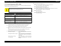
PRECAUTIONS
Precautionary notations throughout the text are categorized relative to 1)Personal injury and 2) damage to equipment.
DANGER
Signals a precaution which, if ignored, could result in serious or fatal personal injury. Great caution should be exercised in performing procedures preceded by
DANGER Headings.
WARNING
Signals a precaution which, if ignored, could result in damage to equipment.
The precautionary measures itemized below should always be observed when performing repair/maintenance procedures.
DANGER
1.
ALWAYS DISCONNECT THE PRODUCT FROM THE POWER SOURCE AND PERIPHERAL DEVICES PERFORMING ANY MAINTENANCE OR REPAIR PROCEDURES.
2.
NO WORK SHOULD BE PERFORMED ON THE UNIT BY PERSONS UNFAMILIAR WITH BASIC SAFETY MEASURES AS DICTATED FOR ALL ELECTRONICS
TECHNICIANS IN THEIR LINE OF WORK.
3.
WHEN PERFORMING TESTING AS DICTATED WITHIN THIS MANUAL, DO NOT CONNECT THE UNIT TO A POWER SOURCE UNTIL INSTRUCTED TO DO SO. WHEN
THE POWER SUPPLY CABLE MUST BE CONNECTED, USE EXTREME CAUTION IN WORKING ON POWER SUPPLY AND OTHER ELECTRONIC COMPONENTS.
4.
WHEN DISASSEMBLING OR ASSEMBLING A PRODUCT, MAKE SURE TO WEAR GLOVES TO AVOID INJURIER FROM METAL PARTS WITH SHARP EDGES.
WARNING
1. REPAIRS ON EPSON PRODUCT SHOULD BE PERFORMED ONLY BY AN EPSON CERTIFIED REPAIR TECHNICIAN.
2.
MAKE CERTAIN THAT THE SOURCE VOLTAGES IS THE SAME AS THE RATED VOLTAGE, LISTED ON THE SERIAL NUMBER/RATING PLATE. IF THE EPSON
PRODUCT HAS A PRIMARY AC RATING DIFFERENT FROM AVAILABLE POWER SOURCE, DO NOT CONNECT IT TO THE POWER SOURCE.
3.
ALWAYS VERIFY THAT THE EPSON PRODUCT HAS BEEN DISCONNECTED FROM THE POWER SOURCE BEFORE REMOVING OR REPLACING PRINTED CIRCUIT
BOARDS AND/OR INDIVIDUAL CHIPS.
4.
IN ORDER TO PROTECT SENSITIVE MICROPROCESSORS AND CIRCUITRY, USE STATIC DISCHARGE EQUIPMENT, SUCH AS ANTI-STATIC WRIST STRAPS, WHEN
ACCESSING INTERNAL COMPONENTS.
5.
DO NOT REPLACE IMPERFECTLY FUNCTIONING COMPONENTS WITH COMPONENTS WHICH ARE NOT MANUFACTURED BY EPSON. IF SECOND SOURCE IC OR
OTHER COMPONENTS WHICH HAVE NOT BEEN APPROVED ARE USED, THEY COULD CAUSE DAMAGE TO THE EPSON PRODUCT, OR COULD VOID THE
WARRANTY OFFERED BY EPSON.
About This Manual
This manual describes basic functions, theory of electrical and mechanical operations, maintenance and repair procedures of the printer. The instructions and procedures included
herein are intended for the experienced repair technicians, and attention should be given to the precautions on the preceding page.
Manual Configuration
This manual consists of six chapters and Appendix.
CHAPTER 1.PRODUCT DESCRIPTIONS
Provides a general overview and specifications of the product.
CHAPTER 2.OPERATING PRINCIPLES
Describes the theory of electrical and mechanical operations of
the product.
CHAPTER 3.TROUBLESHOOTING
Describes the step-by-step procedures for the troubleshooting.
CHAPTER 4.DISASSEMBLY / ASSEMBLY
Describes the step-by-step procedures for disassembling and
assembling the product.
CHAPTER 5.ADJUSTMENT
Provides Epson-approved methods for adjustment.
CHAPTER 6.MAINTENANCE
Provides preventive maintenance procedures and the lists of
Epson-approved lubricants and adhesives required for servicing
the product.
APPENDIX Provides the following additional information for reference:
• Connector pin assignments
• Electric circuit boards components layout
• Electrical circuit boards schematics
• Exploded diagram & Parts List
Symbols Used in this Manual
Various symbols are used throughout this manual either to provide additional
information on a specific topic or to warn of possible danger present during a
procedure or an action. Be aware of all symbols when they are used, and
always read NOTE, CAUTION, or WARNING messages.
A D J U S T M E N T
R E Q U IR E D
C A U T IO N
C H E C K
P O IN T
W A R N IN G
Indicates an operating or maintenance procedure, practice or
condition that is necessary to keep the product’s quality.
Indicates an operating or maintenance procedure, practice, or
condition that, if not strictly observed, could result in damage to,
or destruction of, equipment.
May indicate an operating or maintenance procedure, practice or
condition that is necessary to accomplish a task efficiently. It may
also provide additional information that is related to a specific
subject, or comment on the results achieved through a previous
action.
Indicates an operating or maintenance procedure, practice or
condition that, if not strictly observed, could result in injury or loss
of life.
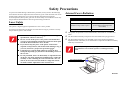
Safety Precautions
To prevent accidents during a maintenance procedure, strictly observe the Warnings
and Cautions and never depart from the instructions given in this document. Do not do
anything that is dangerous even if not specifically described in this manual.
In work operations, always take great care to ensure safety in consideration of not only
the precautions described below but also general safety precautions.
Laser Safety
This printer is digital equipment qualified as a Class 1 laser product.
You will not be exposed to the danger of a laser beam as long as you observe strictly
the precautions given in this manual.
Internal Laser Radiation
Semiconductor Laser Specifications
Laser diode maximum output
Maximum average emission power
Wavelength
15 mw
36.903 µw
(Laser emission opening in the
Print Head)
770 ~ 800 nm
This printer incorporates a Class 3b laser diode, which emits an invisible laser
beam.
W A R N IN G
Be sure to wear a laser protection goggle that meets the applied
specifications, whenever necessary.
Be sure to turn off the power to the printer beforehand when
you start work around the print head or on the laser beam path
around the Photoconductor Unit or the like.
If you need to keep the power to the printer turned on for
required work operations, take off the watch and finger ring, if
you wear, and wear a proper laser protection goggle.
It is dangerous to put any high-reflectivity tool in the laser
beam path. Especially, pay attention to the handling of tools on
the user site.
For the print head, there is no disassembly or adjustment items
on the user site. If the print head is found defective, replace the
assembly or unit containing the control board with a new one.
That is, do not remove the laser diode in a single unit and do
not make trimmer adjustment of the control board.
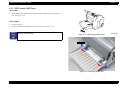
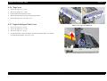
The Print Head Assembly incorporates this laser diode and a polygon mirror.
The Print Head Assembly is not included in the on-the-market maintenance
adjustment items. Therefore, never disassemble or adjust the Print Head Assembly
under any circumstances.
W A R N IN G
Disassembly or adjustment by any procedure other than
prescribed here can result in exposure to an dangerous laser
beam.
Laser emission opening
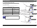
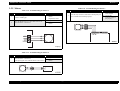
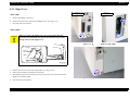
Laser Safety and Caution Labels
Warning labels and caution labels are affixed to this printer for accident prevention.
C H E C K
P O IN T
In maintenance work, check that the labels are free from peeling
and soiling.
Laser safety label
As shown below, a laser safety label is stuck on the rear panel of the printer beside
the AC inlet.
Laser caution label
As shown below, a laser caution label is stuck on the inside of the printer.
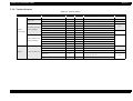
Revision Status
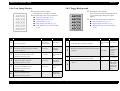
Revision
Date of Issue
A
September 5, 2003
Description
First release
EPSON EPL-6200/EPL-6200L
Revision A
Contents
Chapter 1 Product Description
1.1 Outline ................................................................................................................. 13
1.1.1 Features....................................................................................................... 13
1.1.2 Differences between Models ...................................................................... 16
1.1.2.1 “EPL-6200” Differences from EPL-6100 ........................................... 16
1.1.2.2 “EPL-6200L” Differences from EPL-6100L ...................................... 16
1.1.2.3 Differences between EPL-6200 and EPL-6200L ................................ 16
1.1.3 Other (Only with EPL-6200L).................................................................... 17
1.1.3.1 Restrictions on Use of EPL-6200L ..................................................... 17
1.1.3.2 Operating System ................................................................................ 17
1.2 Basic Specifications............................................................................................. 18
1.2.1 Process Specifications ................................................................................ 18
1.2.2 Printer Basic Specifications........................................................................ 18
1.2.3 Paper Specification ..................................................................................... 26
1.2.3.1 Paper Type........................................................................................... 26
1.2.3.2 Paper Feedings .................................................................................... 26
1.2.3.3 Printable Area...................................................................................... 27
1.2.4 Reliability, Durability, Serviceability......................................................... 27
1.2.4.1 Reliability ............................................................................................ 27
1.2.4.2 Durability............................................................................................. 28
1.2.4.3 Serviceability....................................................................................... 28
1.2.5 Operating Conditions (Including Consumables) ........................................ 29
1.2.6 Storage and Transport of the Printer Main Unit and Optional Products (Consumables Packaged)................................................................................... 30
1.2.7 Electrical Features ...................................................................................... 30
1.2.8 Compliance with Standards and Regulations ............................................. 31
1.2.9 Consumable Components ........................................................................... 32
1.2.9.1 Specifications ...................................................................................... 32
1.2.9.2 Packing Storage and Transport Environments .................................... 32
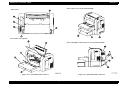
1.3 External Appearance and Parts Name ................................................................. 33
1.3.1 Overall Dimensions of EPL-6200 .............................................................. 33
1.3.2 Overall Dimensions of EPL-6200L ............................................................ 34
1.3.3 Names of Parts of EPL-6200 ...................................................................... 35
1.3.4 Names of Parts of EPL-6200L....................................................................
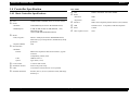
1.4 Controller Specification ......................................................................................
1.4.1 Basic Controller Specifications ..................................................................
1.4.2 External I/F Specifications .........................................................................
1.4.2.1 Parallel Interface Specifications..........................................................
1.4.2.2 USB Interface ......................................................................................
1.4.2.3 Type B Interface (Not Available with EPL-6200L)............................
1.5 Control Panel (EPL-6200)...................................................................................
1.5.1 External Appearance and Names of Parts ..................................................
1.5.2 List of Settings............................................................................................
1.5.3 Printer Messages.........................................................................................
1.5.4 Special Operation (EPL-6200) ...................................................................
1.6 Control Panel (EPL-6200L) ................................................................................
1.6.1 External Appearance and Names of Parts ..................................................
1.6.2 Printer Setting Items ...................................................................................
1.6.3 Status ..........................................................................................................
1.6.3.1 Status List............................................................................................
1.6.3.2 Details of Status Messages and Processing.........................................
1.6.3.3 Details of Error Status and Processing ................................................
1.6.3.4 Details of Warning Status and Processing ..........................................
1.6.4 Special Operation (EPL-6200L) .................................................................
1.6.4.1 EEPROM Initialization .......................................................................
1.6.4.2 Printer Adjustment (Hidden Function)................................................
1.7 RAM Expansion ..................................................................................................
1.8 System Requirements (Only for EPL-6200L).....................................................
1.9 Paper Feed Specifications (Only for EPL-6200L) ..............................................
1.9.1 Paper Size ...................................................................................................
1.9.2 Paper Feed Specifications...........................................................................
1.9.3 Case List .....................................................................................................
1.9.4 Special Notes ..............................................................................................
1.10 Notes on Operation............................................................................................
1.10.1 Power Off (EPL-6200) .............................................................................
1.10.2 Caution About Hot Parts (EPL-6200/EPL-6200L) ..................................
37
38
38
39
39
40
40
41
41
41
44
46
47
47
48
49
49
49
50
53
54
54
55
57
57
58
58
58
59
59
60
60
60
8
EPSON EPL-6200/EPL-6200L
1.10.3 About the Moist Environment Mode Select .............................................
1.11 Status Sheet .......................................................................................................
1.12 Ambient Conditions...........................................................................................
1.13 Differences in Specifications between Intended Markets .................................
1.13.1 Differences in Specifications ....................................................................
1.13.2 Jumper Setting ..........................................................................................
1.14 Notes on Installation of Optional Units.............................................................
Revision A
60
61
64
65
65
66
66
Chapter 2 Operating Principles
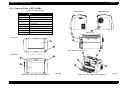
2.1 Overview .............................................................................................................
2.1.1 EPL-6200 Major Components ....................................................................
2.1.2 EPL-6200L Major Components .................................................................
2.1.3 Paper Path ...................................................................................................
2.1.4 Electrical Parts ............................................................................................
2.1.5 Operation Sequence ....................................................................................
2.1.6 Various Sensors ..........................................................................................
2.2 Description of Mechanisms.................................................................................
2.2.1 Print Head (PH) ..........................................................................................
2.2.1.1 Entire Constitution ..............................................................................
2.2.1.2 Exposure Process.................................................................................
2.2.1.3 Laser Emission Timing .......................................................................
2.2.1.4 Laser Emission Area ...........................................................................
2.2.1.5 Cooling inside the Printer....................................................................
2.2.2 Charging Process ........................................................................................
2.2.3 Development Process (Imaging Cartridge) ................................................
2.2.3.1 OVERVIEW........................................................................................
2.2.3.2 OPC Drum ...........................................................................................
2.2.3.3 Development Process ..........................................................................
2.2.3.4 Detection Of Developer Cartridge (toner cartridge) ...........................
2.2.4 Transfer Process..........................................................................................
2.2.5 Fusing Process ............................................................................................
2.2.5.1 Overview .............................................................................................
2.2.5.2 Fusing Temperature Control ...............................................................
2.2.6 Paper Feed Mechanism...............................................................................
2.2.6.1 MP (Multiple Purpose Paper) Tray .....................................................
2.2.6.2 Manual Paper Feeding (EPL-6200).....................................................
2.2.7 Lower Cassette (Option for EPL-6200)......................................................
2.2.7.1 Locations of Electrical Parts................................................................
68
68
69
70
71
72
73
74
74
74
74
75
75
76
77
78
78
79
80
81
82
83
83
83
85
85
86
87
87
2.2.7.2 Paper Feed Mechanism .......................................................................
2.2.7.3 Paper Cassette Empty Sensor ..............................................................
2.2.7.4 Cassette Type Sensor ..........................................................................
2.2.8 Paper Eject Process.....................................................................................
2.2.8.1 Paper Eject Mechanism .......................................................................
2.2.9 Duplex Unit (option) ..................................................................................
2.2.9.1 Locations of Electrical Parts ...............................................................
2.2.9.2 Driving of Duplex Unit .......................................................................
2.2.9.3 Paper Feeding System .........................................................................
2.3 Operating Principles of Electric Circuitry...........................................................
2.3.1 Operation Overview of the Main Control Circuit Board............................
2.3.1.1 Main Control Circuit Board (C533 MAIN) for EPL-6200 .................
2.3.1.2 Main Control Circuit Board (C533Main) for EPL-6200L ..................
87
88
88
89
89
90
90
91
92
94
94
94
98
Chapter 3 Troubleshooting
3.1 Overview ...........................................................................................................
3.1.1 Specified Tools .........................................................................................
3.1.2 Procedure for Troubleshooting.................................................................
3.1.3 Preliminary Checks...................................................................................
3.1.4 Notes on Troubleshooting ........................................................................
3.1.5 Overall Control System ............................................................................
3.1.6 Printer Messages (EPL-6200)...................................................................
3.1.6.1 Service Call Error..............................................................................
3.1.7 Printer Messages (EPL-6200L) ................................................................
3.2 Troubleshooting When There is Error Display .................................................
3.2.1 Fuser warming up problem.......................................................................
3.2.2 Fan problem ..............................................................................................
3.2.3 Polygon Motor Error ................................................................................
3.2.4 Laser problem ...........................................................................................
3.2.5 High voltage circuit problem....................................................................
3.2.6 Fuser high temperature problem...............................................................
3.2.7 CPU Error .................................................................................................
3.2.8 Engine Communication Error...................................................................
3.2.9 Fuser low temperature problem ................................................................
3.2.10 Standard RAM Error ..............................................................................
3.2.11 RAM Error (Slot 0).................................................................................
3.2.12 ROM Checksum Error (Font).................................................................
3.2.13 ROM Checksum Error (Program) ..........................................................
3.2.14 Option ROM Error..................................................................................
100
100
100
101
101
101
102
102
106
107
107
108
108
109
109
110
110
110
111
112
112
113
113
114
9
EPSON EPL-6200/EPL-6200L
Revision A
3.2.15 EEPROM Error....................................................................................... 114
3.2.16 Engine Initialization Error ...................................................................... 115
3.2.17 Other Hardware Error ............................................................................. 115
3.2.18 Software Error ........................................................................................ 115
3.3 Troubleshooting for Paper Jam ......................................................................... 116
3.3.1 Initial Checking ........................................................................................ 116
3.3.2 Locations of Paper Jam Detection Sensors............................................... 116
3.3.3 Jam Detection Timing / Action to be Taken............................................. 117
3.3.3.1 Paper Feed Area Jam / Paper Transport Area Jam ............................ 117
3.3.3.2 Fuser Area Jam / Paper Eject Area Jam ............................................ 117
3.3.3.3 Transport Area Jam in Duplex Unit (Option) ................................... 118
3.3.3.4 Paper Re-feed Area Jam in Duplex Unit (Option) ............................ 118
3.4 Troubleshooting for Abnormal Operations ....................................................... 119
3.4.1 Power Cannot be Turned ON ................................................................... 119
3.4.2 Electrical Noise......................................................................................... 120
3.5 Troubleshooting for Electrical Parts.................................................................. 121
3.5.1 Checking Method for Electrical Parts....................................................... 121
3.5.2 Sensors...................................................................................................... 121
3.5.3 Switches .................................................................................................... 121
3.5.4 Solenoids................................................................................................... 121
3.5.5 Motors....................................................................................................... 122
3.6 Troubleshooting for Print Quality Problems ..................................................... 123
3.6.1 Blank Print or Solid Black ........................................................................ 124
3.6.2 White Out.................................................................................................. 125
3.6.3 Back of Paper Gets Dirty .......................................................................... 125
3.6.4 Low Image Density................................................................................... 126
3.6.5 Foggy Background.................................................................................... 126
3.6.6 White Stripes or White Bands .................................................................. 127
3.6.7 Black Stripes or Black Bands ................................................................... 127
3.6.8 Offset Image ............................................................................................. 128
Chapter 4 Disassembly and Assembly
4.1 Overview ...........................................................................................................
4.1.1 Precautions................................................................................................
4.1.2 Tools .........................................................................................................
4.1.3 Screws.......................................................................................................
4.1.4 Main Unit Disassembly ............................................................................
4.2 Consumables and Regular Replacement Parts ..................................................
130
130
131
131
132
134
4.2.1 Locations of Fuses ....................................................................................
4.2.2 Paper Feed Roller .....................................................................................
4.2.3 Developer Cartridge / Photoconductor Unit Replacement .......................
4.2.4 Transfer Roller..........................................................................................
4.3 Removal of Covers............................................................................................
4.3.1 Left Cover.................................................................................................
4.3.2 Right Cover...............................................................................................
4.3.3 MP Cassette (MP Tray) ............................................................................
4.3.4 Front Cover...............................................................................................
4.3.5 Output Tray...............................................................................................
4.3.6 Top Cover .................................................................................................
4.3.7 Paper Exit Open/Close Cover...................................................................
4.3.8 Paper Exit Cover.......................................................................................
4.3.9 Upper Rear Cover.....................................................................................
4.3.10 Lower Rear Cover ..................................................................................
4.4 Removal and Installation of Circuit Boards ......................................................
4.4.1 Main Board Assy (C533/C534 Main) ......................................................
4.4.1.1 EPL-6200 (C533 Main).....................................................................
4.4.1.2 EPL-6200L (C534 Main) ..................................................................
4.4.2 Parallel I/F Board (EPL-6200) .................................................................
4.4.3 USB I/F Board (EPL-6200)......................................................................
4.4.4 Control Panel ............................................................................................
4.4.5 Power Supply Unit (PU1).........................................................................
4.4.6 High Voltage Unit (HV1) .........................................................................
4.5 Removal and Installation of Major Components ..............................................
4.5.1 Fuser Unit .................................................................................................
4.5.2 Fuser Unit Disassembly............................................................................
4.5.3 PH Unit .....................................................................................................
4.5.4 Main Motor...............................................................................................
4.5.5 Cooling Fan Motor ...................................................................................
4.5.6 Paper Tray Empty Sensor (EPL-6200 only).............................................
4.5.7 Paper Feed Solenoid .................................................................................
4.5.8 Paper Feed Clutch Gear ............................................................................
4.6 Lower Cassette Unit (Option) ...........................................................................
4.6.1 Second Paper Feed Unit ...........................................................................
4.6.2 Paper Feed Roller (Lower Cassette) .........................................................
4.6.3 Paper Feed Solenoid (Lower Cassette).....................................................
4.6.4 Paper Cassette Unit Control Board...........................................................
4.6.5 Paper Size Detect Switch..........................................................................
134
134
135
136
137
138
139
140
141
141
142
142
143
143
144
145
146
146
148
149
149
150
151
151
152
152
153
154
155
155
156
157
158
160
160
161
161
162
162
10
EPSON EPL-6200/EPL-6200L
4.7 Duplex Unit (Option) ........................................................................................
4.7.1 Right Cover...............................................................................................
4.7.2 Left Cover .................................................................................................
4.7.3 Duplex Unit Control Board ......................................................................
4.7.4 Duplex Unit Inversion Motor ...................................................................
4.7.5 Duplex Unit Transport Motor ...................................................................
4.7.6 Duplex Unit Skew Correction Solenoid ...................................................
Revision A
163
163
163
163
164
164
164
Chapter 5 Adjustment
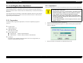
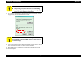
5.1 Overview ...........................................................................................................
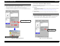
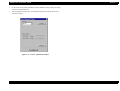
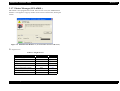
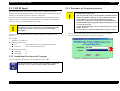
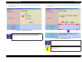
5.2 USB ID Input.....................................................................................................
5.2.1 Installation Procedure for Program...........................................................
5.2.2 Procedure for Program Operation.............................................................
5.3 Feed Registration Adjustment ...........................................................................
5.3.1 Preparation ................................................................................................
5.3.2 Adjustment................................................................................................
166
167
167
167
169
169
169
Chapter 6 Maintenance
6.1 Overview ...........................................................................................................
6.1.1 Cleaning ....................................................................................................
6.1.2 Maintenance..............................................................................................
6.1.3 Cleaning of Paper Feed Rollers ................................................................
173
173
173
174
Chapter 7 Appendix
7.1 Connectors.........................................................................................................
7.1.1 Connectors on Main Board Assy (EPL-6200)..........................................
7.1.2 Connectors on Main Board Assy (EPL-6200L) .......................................
7.1.3 Connector Assignment Diagram (Overall) ...............................................
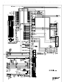
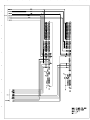
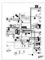
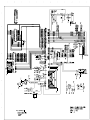
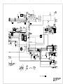
7.2 Circuit Diagrams ...............................................................................................
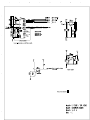
7.3 Exploded Diagrams ...........................................................................................
7.4 ASP List.............................................................................................................
176
176
177
178
179
186
197
11
1
CHAPTER
PRODUCT DESCRIPTION
EPSON EPL-6200/EPL-6200L
Revision A
1.1 Outline
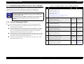
Toner life
Table 1-2. Toner Life
EPSON EPL-6200 and EPSON EPL-6200L are non-impact page printer with
semiconductor laser and electrophotographic technology.
1.1.1 Features
Model
Initial
EPL-6200
3000 pages
EPL-6200L
1500 pages
Replacement
3000 pages
6000 pages
3000 pages
ENGINE FEATURES
Photoconductor Unit
A compact and lightweight A4 engine.
The Photoconductor Unit can be assembled with the Developer Cartridge (toner
cartridge) into a single unit.
High resolution and high printing speed.
See table below.
Table 1-1. Resolution and Printing Speed
Model
EPL-6200
EPL-6200L
Resolution
Printing Speed
300 dpi / 600 dpi
20 ppm
1200 dpi
10 ppm
600 dpi
20 ppm
Photoconductor Unit
Note : The engine itself supports True 1200 dpi, but 1200 dpi is not supported with
EPL-6200L.
With EPL-6200, the standard paper supply consists of the cassette-like universal
paper tray (250 sheets) and manual feed tray (one sheet).
EPL-6200 supports an optional 500-sheet lower cassette (A4 size).
EPL-6200L is equipped with a 150-sheet paper feed tray.
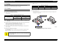
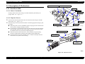
Imaging Cartridge
EPL-6200 supports an optional Duplex Unit (requiring paper loading from the
Developer Cartridge
(toner cartridge)
lower cassette).
Developer Cartridge (toner cartridge)
New type Developer Cartridge (removal and installation together with the
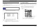
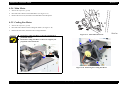
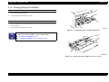
Figure 1-1. Imaging Cartridge Constitution
OPC drum)
CSIC (It detects Toner capacity and brand-new toner automatically.)
C A U T IO N
There is no interchangeability between the Developer Cartridges
for EPL-6200/EPL-6200L and those for the previous models “EPL6100 / EPL-6100L”.
Product Description
Outline
13
EPSON EPL-6200/EPL-6200L
CONTROLLER FEATURES
<EPL-6200>
High-speed controller
CPU
: TMPR4955BFG 200 MHz (Same as for EPL-N2500)
RAM
: 8 MB fitted as standard RAM and Expandable up to 136 MB
Max.
Exclusive RAM DIMM for EPSON (Same as for EPL-6100)
Equipped with one Type B interface slot (Level 3 supported)
Two standard interfaces
IEEE1284 parallel interface
USB interface
Real 1200dpi supported
(Only in ESC/Page, PCL6, PostScript 3. Up to 600 dpi supported in other modes)
NOTE:
1200 dpi printing needs much memory. At 1200 dpi printing,
therefore, the possibility of running short of memory is high with
standard memory.
Recommendation: Extension of 16 MB or more.
Revision A
<EPL-6200L>
Host-based controller
CPU
: EPSON 32 bit RISC S1C33000 48 MHz
RAM
: Standard RAM is 2 MB
RAM can be not expanded.
Two standard interfaces
IEEE1284 compatible parallel interface supporting ECP.
USB interface (USB revision 1.1, supporting USB ID).
Data compression technology
Sending compressed data from a host computer allows printing most of the
data with only standard memory.
An expanded circuit hardware provides high-speed processing.
No toner save mode
No 300 dpi mode
No RITech or PGI (EnhancedMicroGray)
EnhancedMicroGray installed (available only in 600 dpi and 300 dpi.
Automatically switched off when 1200 dpi is selected.)
RITech installed (available only in 600 dpi and 300 dpi. Automatically switched
off when 1200 dpi is selected.)
PCL6 emulation is installed as a standard feature.
Adobe PostScript3 is installed as a standard feature.
No optional ROM DIMM slot.
Product Description
Outline
14
EPSON EPL-6200/EPL-6200L
Revision A
SOFTWARE FEATURE (ONLY WITH EPL-6200)
OTHER FEATURE (ONLY WITH EPL-6200L)
Printer status and printer environment are monitored by bidirectional EJL and
Toner save image is made by Printer Driver.
ESC/Page.
Physical engine offset setting function (It is set by printer driver)
The following modes and resolution are supported.
Printer sharing (Printer driver’s function)
Table 1-3. Supported Modes
1200dpi
600dpi
300dpi
{
ESC/Page
{
{
PCLXL
{
{
{
PCL5e
X
{
{
ESC/P2
X
{
{
FX
X
{
{
I239X
X
{
{
PostScript3
{
{
{
Note
NLSP is included in the main unit font ROM
Compatible with USB Revision 1.1
Job cancellation by panel switch
Mechanical Controller update function (effective only when Mechanical
Controller is Flash)
Firmware update function (effective only when Program ROM is Flash) (crb
format files (rcc format files supported with RAM expanded to 32 MB))
Job MIB supported
Firmware operation area
Table 1-4. Firmware Operation Area
Module
Expanded RAM
Other than PS3
PS3
Less than 32 MB
ROM
ROM
32 MB
RAM
ROM
64 MB or more
RAM
RAM
Product Description
Outline
15
EPSON EPL-6200/EPL-6200L
Revision A
1.1.2 Differences between Models
1.1.2.2 “EPL-6200L” Differences from EPL-6100L
Printing speed is 20 ppm (EPL-6100L: 16 ppm)
1.1.2.1 “EPL-6200” Differences from EPL-6100
CSIC with Developer Cartridge (toner cartridge)
Table 1-5. “EPL-6200” Differences from EPL-6100
Item
EPL-6200
EPL-6100
20 ppm
16 ppm
Face up tray (Option)
Not available
Available
Optional DIMM slot
Provided
Provided
Duplex Unit
Optional
Not available
Developer Cartridge
part number
New type
Not interchangeable
OPC drum
New type
Not interchangeable
Toner CSIC
Provided
Not provided
Font vendor
AGFA
Bitstream
Engine speed
PS3
Standard
Optional
MIB
JOB MIB
SystemWalker MIB
7 steps
5 steps
Rendezvous=On,Off
Provided
Not provided
Manual Feed mode
1st Page, EachPage added
On only
Toner counter / OPC drum life
level indication
Symbolset
Setting by driver
Jumper setting
Physical offset setting
Available
(Setting by driver)
Not available
Available
Not available
Jam error
Composite error
Priority order
Cover Open error
Composite error
Priority order
Composite warning
Priority order
Available
Not available
Consumables warning
Engine program ROM update
function
Program operation area
Product Description
The ECP/Nibble switch jumper is disused.
The High humidity/Normal humidity switch jumper is disused. (The setting is
enable by printer driver)
Engine offset adjustment (It is adjusted by printer driver)
Related SelecType
and errors added
Related errors added
Registration position (paper feed direction) adjustment function (It is set at factory
only.)
1.1.2.3 Differences between EPL-6200 and EPL-6200L
Table 1-6. Differences between EPL-6200 and EPL-6200L
Item
ROM (RAM depending on
RAM capacity)
Added to EJL
Effective only when
Mechanical
Controller is flash
Always RAM
Outline
EPL-6200
EPL-6200L
Font, Program
16 MB Mounted
Not mounted
Emulation
Mounted
PCLXL, PCL5e, GL/2, FX,
ESCP2, I239X, ESC/Page,
PostScript 3
Not mounted
(No option)
Resolution
300 / 600 / 1200 dpi
600 dpi
Expansion RAM
SD RAM DIMM
None
Network
Supported with a Type B slot
Direct connection not supported
Shared Printer is supported on
Windows, but not supported on
Macintosh
Standard paper feeder
Universal paper tray
(250 sheets)
Folding tray type
(150 sheets)
Optional unit
Lower paper cassette available
(Only one stage)
Lower paper cassette not
available
Control Panel
3 switches and 6 LEDs
No switches and 2 LEDs
Toner save mode
Mounted
Not mounted
(Available by printer driver)
AUX I/F Menu
Added (LJ4, ESCP2)
High humidity setting
Feed Regist adjustment
Note
16
EPSON EPL-6200/EPL-6200L
Revision A
1.1.3 Other (Only with EPL-6200L)
1.1.3.1 Restrictions on Use of EPL-6200L
The printer itself cannot print the Status Sheet.
When the printer is connected to a parallel interface, printing via devices such as a
printer switch, LAN-Parallel converter, or USB-Parallel converter is not
guaranteed.
→ Direct connection to a printer port of the host computer with an ECP supporting
cable is premised. Using a converter for a USB connection is not guaranteed.
This printer cannot be used in environments where a bi-directional port is not
supported, for example, where a terminal server is used.
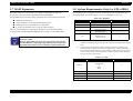
1.1.3.2 Operating System
Table 1-7. Operating System
OS
C H E C K
P O IN T
Version
Windows
Windows 95/98/Me/XP/2000, NT 4.0
Macintosh
Mac OS 8.6 or later, 9.x, 10.1.2 or later only
Other systems such as DOS, Unix, Linux are not supported.
Only personal computers operating on Macintosh or Windows
equipped with a USB port as standard can be used.
NOTE: For details, see “1.8 System Requirements (Only for EPL-6200L) (p.57)”.
Product Description
Outline
17
EPSON EPL-6200/EPL-6200L
Revision A
1.2 Basic Specifications
1.2.2 Printer Basic Specifications
Resolution:
1.2.1 Process Specifications
Table 1-8. Resolution
Printer Type
Semi-conductor laser beam scan and dry single-component non-electromagnetic
toner electrophotography
Light Source
Semi-conductor laser
Photoconductor Unit
OPC (organic photoconductor) drum
Model
Resolution
Note
EPL-6200
600 dpi/1200dpi
1200 dpi is by half speed control
EPL-6200L
600 dpi
Warming Up Time:
21 or less seconds...... Time from power-on to “Ready” display
16 or less seconds...... Time from low power consumption mode to “Ready”
display
(23°C environment, at rated voltage)
Charging
Rotary-brush charging method
Development
First Printing Time:
Exposed area development
Table 1-9. First Printing Time (Unit: seconds max.)
Toner
EPL-6200
One-component non-magnetic toner
Transfer
Roller transfer method
Paper
Size
Density Adjustment
Variable development bias method (adjustable by user)
1200 dpi
600 dpi
Main
Unit
Lower
Cassette
Unit
Duplex
Printing
Main
Unit
Lower
Cassette
Unit
Duplex
Printing
Main Unit
A4
13
16
24
22
24
37
13
LGL
14
-
-
24
-
-
14
LT
13
16
24
22
-
37
13
B5
13
-
24
22
-
37
13
A5
12
-
-
21
-
-
12
Fixing
Heated roller method
600 dpi
EPL-6200L
Continuous Printing Speed:
Printing speed mode
• Normal paper mode: Printing is performed at the highest speed available with
the main unit. (Labels and transparencies are included)
• Thick paper mode: Printing is performed with the paper feed interval extended
in order to maintain the print quality of Thick Papers. (“ppm
down” may take place.) (Since the paper feed interval of
envelopes or Japanese postcards is the maximum, there is
no “ppm down”.)
Product Description
Basic Specifications
18
EPSON EPL-6200/EPL-6200L
Revision A
Normal paper (including labels and transparencies)
Thick paper
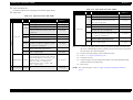
Table 1-10. Continuous Printing Speed with Plain Paper (Unit: ppm or more)
EPL-6200
Paper
Size
EPL-6200L
Simplex
Duplex
Simplex
600 dpi
600 dpi
1200 dpi
A4
20.0
LGL
EPL-6200
Paper Size
600 dpi
1200 dpi
2-sheet
circulation
1-sheet
circulation
2-sheet
circulation
10.0
10.4
13.5
5.2
6.7
20.0
16.0
8.0
-
-
-
-
16.0
LT
20.0
10.0
10.4
13.5
5.2
6.7
20.0
B5
20.0
10.0
10.4
13.5
5.2
6.7
20.0
A5
20.0
10.0
-
-
-
-
20.0
EXE
20.0
10.0
-
-
-
-
20.0
HLT
20.0
10.0
-
-
-
-
20.0
Note : The continuous printing speeds indicated above are common to all the paper
feeders.
EPL-6200L
1200 dpi
ppm down*
600 dpi
1-sheet
circulation
Product Description
Table 1-11. Continuous Printing Speed with Thick Paper (Unit: ppm or more)
600 dpi
ppm down*
6.0
ppm down*
A4
16.0
12.0
8.0
16.0
12.0
LGL
13.0
10.0
6.5
5.0
13.0
10.0
LT
16.0
12.0
8.0
6.0
16.0
12.0
B5
16.0
12.0
8.0
6.0
16.0
12.0
A5
16.0
12.0
8.0
6.0
16.0
12.0
EXE
16.0
12.0
8.0
6.0
16.0
12.0
HLT
16.0
12.0
8.0
6.0
16.0
12.0
Japanese official
postcard
12.0
-
6.0
-
12.0
-
Envelopes
12.0
-
6.0
-
12.0
-
Note “*”: For ppm down start timing, see “Thick paper ppm control (p.20)”.
Basic Specifications
19
EPSON EPL-6200/EPL-6200L
Revision A
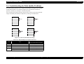
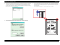
Thick paper ppm control
For thick paper printing, sheets of paper is fed at wider intervals (ppm Down) as
described below to prevent temperature rise at both ends of the fuser unit.
The ppm Down control will be started after a lapse of 100 seconds from the
start of Thick Paper printing.
NOTE:
However, if the motor has already been running for more than
100 seconds to execute jobs (continuous or intermittent
printing) before starting thick paper printing, the ppm Down
control is started at the beginning of Thick Paper printing.
The motor running period of time for previous jobs is
accumulated irrespective of paper types.
The motor running time will be reset when the printer keeps in standby status
for 3 minutes.
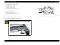
See Figure 1-2, "Cases of ppm Down (for reference only)".
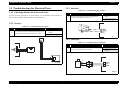
t: Motor running time (printing time)
ts: Standby time
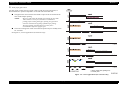
Figure 1-2. Cases of ppm Down (for reference only)
Product Description
Basic Specifications
20
EPSON EPL-6200/EPL-6200L
Revision A
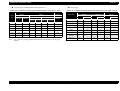
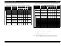
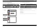
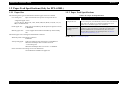
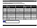
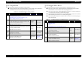
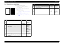
Paper Feed Reference
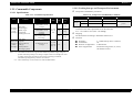
Table 1-13. Paper Feed with “EPL-6200L”
Centerline reference for each paper size and each paper feeder.
Paper Source
Paper Feed:
180 sheets Standard paper: FX-P Paper: A4
Table 1-12. Paper Feed with “EPL-6200”
Capacity
Paper Type
and Paper Size
300 sheets Standard paper: FX-P Paper: A4
Standard paper: XEROX 4024DP 20lb: Letter
Standard paper: RX-80: A4
250 sheets
5 sheets
Standard
Paper Tray
Plain paper or regenerated paper:
A4, B5, A5, Letter, GLT, Executive, LGL, GLG,
F4, Half Letter
80
g/m2
60∼90 g/m2
Labels: A4, Letter
10 sheets Thick paper: A4, B5, A5, Letter, GLT,
Executive, LGL, GLG, F4, Half Letter
-
Japanese official postcard *1,
Japanese official reply-paid postcard *1
Height Custom size paper *5: 76.00 ~ 216.00 in width
29.5 mm 127.00 ~ 356.00 in length
Optional
75 g/m2
-
50 sheets*2
1 sheets
Standard paper, plain paper, special applications:
A4, A5, Letter, GLT, Executive, LGL, GLG, F4,
Half Letter, B5, Monarch, Com-10, DL, C5, C6,
ISO-B5, Yokei #0*6, Yokei #4*6, Yokei #6*6,
Chokei #3*6, Chokei #4*6, Kakugata #3*6
Custom size paper: 76.00 ~ 216.00 in width
127.00 ~ 356.00 in length
Lower cassette *4 500 sheets A4
Product Description
150 sheets Plain paper or regenerated paper:
A4, B5, ISO-B5, A5, Letter, GLT, Executive,
LGL, GLG, F4, Half Letter
64 g/m2
Transparencies: A4, Letter
Envelope: Monarch, Com-10, DL, C5, C6, ISO10 sheets B5, Yokei #0*6, Yokei #4*6, Yokei #6*6, Chokei
#3*6, Chokei #4*6, Kakugata #3*6
Manual feed tray
Standard paper: XEROX 4024DP 20lb: Letter
Feedable Paper
Thickness *3
5 sheets
Standard
Paper Source
*3
Paper Type *3 and Paper Size
Capacity
Paper Tray
Transparencies: A4, Letter
Labels: A4, Letter
10 sheets Thick paper: A4, B5, ISO-B5, A5, Letter, GLT,
Executive, LGL, GLG, F4, Half Letter
Envelope: Monarch, Com-10, DL, C5, C6, ISO10 sheets B5, Yokei #0*6, Yokei #4*6, Yokei #6*6, Chokei
#3*6, Chokei #4*6, Kakugata #3*6
50 sheets*2
90∼163 g/m2
Height
16 mm
70∼105g/m2
190 g/m2
60∼163g/m2
Japanese official postcard *1,
Japanese official reply-paid postcard *1
Custom size paper*5: 76.00 ~ 216.00 in width
127.00 ~ 356.00 in length
Feedable Paper
Thickness *3
64 g/m2
75 g/m2
60∼90 g/m2
90∼163 g/m2
70∼105g/m2
190 g/m2
60∼163g/m2
Note “*1”: Curl must be straightened before feeding a postcard for printing of its back side in
the course of manual duplex printing. (Set the postcard so that its side to be printed
faces up and its curl is directed upward.)
“*2”: For the second side printing, set not more than 20 sheets.
“*3”: Refer to “1.2.3 Paper Specification (p.26)”.
“*4”: Cassette for A4 only
60∼163 g/m2*4
“*5”: Custom size paper for special applications must not exceed the permitted setting
number of sheets for each paper type.
“*6”: JIS envelope
60∼90 g/m2
NOTE: For custom size paper, refer to“ Paper Feed Sizes and Paper Thickness
(p.23)”.
Basic Specifications
21
EPSON EPL-6200/EPL-6200L
Revision A
Available Paper Sizes, Paper Types, and Paper Orientation
Table 1-14. Available Paper Sizes, Paper Types, and Paper Orientation
Table 1-14. Available Paper Sizes, Paper Types, and Paper Orientation
Dimensions
Length x Width
in mm (inches)
MP
Tray
Paper Size
Paper
Manual Lower
Duplex Paper Orientation
Feed Cassette
Unit *4 Tray
*4
Tray
EPL6200L
EPL-6200
MP
Tray
Paper
Manual Lower
Duplex Paper Orientation
Feed Cassette
Unit *4 Tray
*4
Tray
297.00 x 210.00
{
{
{*3
{
{
SEF
A5
210.00 x 148.00
{
{
−
−
{
SEF
B5
257.00 x 182.00
{
{
−
{
{
SEF
Transparencies
{
{
−
−
{
SEF
ISO-B5*5
250.00 x 176.00
{
{
−
−
{
SEF*2
A4: 297.00 x 210.00
LT: 279.40 x 215.90
{
{
{
SEF
A4: 97.00 x 210.00
LT: 279.40 x 215.90
{
{
−
{
−
Labels
−
{
SEF
LT
279.40 x 215.90
(11.00” x 8.50”)
215.90 x 139.70
(8.50” x 5.50”)
−
{
190.5 x 98.43
(7 1/2” x 3 7/8”)
{
{
−
{
SEF
MON
{
−
−
{
SEF*2
HLT
355.60 x 215.90
(14.00” x 8.50”)
{
SEF
241.30 x 104.78
(9 1/2” x 4 1/8”)
{
{
−
{
−
C10
{
−
−
{
SEF*2
LGL
DL
220.00 x 110.00
{
{
−
−
{
SEF*2
EXE
266.70 x 184.15
(10.50” x 7.25”)
{
C5
229.00 x 162.00
{
{
−
−
{
SEF*2
330.20 x 215.90
(13.00” x 8.50”)
C6
162.00 x 114.00
{
{
−
−
{
SEF*2
GLG
Yokei #0 *6
235.00 x 120.00
{
{
−
−
{
SEF*2
GLT
266.70 x 203.20
(10.50” x 8.00”)
{
{
−
−
{
SEF
*6
235.00 x 105.00
{
{
−
−
{
SEF*2
F4
330.00 x 210.00
{
{
−
−
{
SEF
{
{
−
{
−
−
−
{
SEF
{
SEF
Envelope*2
A4
Japanese official
postcard*1
Japanese official
reply-paid postcard *1
Special Applications
Plain Paper
Paper Size
EPL6200L
EPL-6200
Dimensions
Length x Width
in mm (inches)
Yokei #4
148.00 x 100.00
{
{
−
−
{
SEF
200.00 x 148.00
{
{
−
−
{
SEF
190.00 x 98.00
{
{
−
−
{
SEF*2
Chokei #3
*6
235.00 x 120.00
{
{
−
−
{
SEF*2
Chokei #4
*6
205.00 x 90.00
{
{
−
−
{
SEF*2
277.00 x 216.00
{
{
−
−
{
SEF*2
Yokei #6 *6
Kakugata #3 *6
Note “*1”: Curls must be straightened for duplex printing by manual feeding.
“*2”: Refer to “Envelope Orientation (p.23)”for details on feeding direction of
envelopes.
“*3”: The lower cassette is available with a fixed paper size.
“*4”: Option
“*5”: ISO-B5 can be handled also as an envelope.
“*6”: JIS envelope
Note : LEF (Long Edge Feed):the long edge of the paper is fed to the printer.
SEF (Short Edge Feed):the short edge of the paper is fed to the printer.
Product Description
Basic Specifications
22
EPSON EPL-6200/EPL-6200L
Revision A
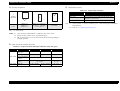
Envelope Orientation
Output Paper Capacity
Table 1-16. Output Paper Capacity:
Standard
↑
Feeding
Direction
Envelope
Types
Output paper capacity
Chokei #3 *1,
Chokei #4 *1,
Kakugata #3 *1
Yokei #0 *1, Yokei #4 *1,
Yokei #6 *1, Monarch,
Com-10, DL, C6
C5, ISO-B5
*1
100 sheets
Paper sizes
All sizes which can be fed through the printer body
(Regular or custom sizes)
Paper types *2
Standard paper, plain paper, special applications
Note “*1”: In Environment A “Ambient Conditions (p.64)”. With standard paper immediately
after unpacked
“*2”: Refer to “1.2.3 Paper Specification (p.26)”.
Note “*1”: JIS envelope
NOTE 1: Only envelopes without adhesive or adhesive tapes can be used.
2: Set the envelope with its side to be printed facing up.
3: JIS envelopes must be set in the directions as shown above depending on
their flap positions.
Paper Feed Sizes and Paper Thickness
Table 1-15. Paper Feed Sizes and Paper Thickness (Unit: mm, g/m2)
Model
Paper Source
Printer body and
Paper tray
Manual feed tray
EPL-6200 Lower cassette unit
(option)
Duplex Unit
(option)
EPL-6200L Main unit
Product Description
Paper width
Paper length
Paper thickness
76.00 ~ 216.00
127.00 ~ 356.00
60 ~ 163
76.00 ~ 216.00
148.00 ~ 356.00
60 ~ 163
A4 only
60 ~ 90
A4, LT, B5
60 ~ 90
76.00 ~ 216.00
127.00 ~ 356.00
60 ~ 163
Basic Specifications
23
EPSON EPL-6200/EPL-6200L
Revision A
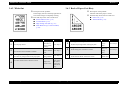
Dimensions and Weight
<EPL-6200L>
Stand Alone Outline Dimensions and Weights
<EPL-6200>
Table 1-19. Stand Alone Outline Dimensions and Weights of “EPL-6200L”
Stand Alone Outline Dimensions and Weights
Width
(mm)
Depth
(mm)
Height
(mm)
Weight
(kg)
Output tray in
storage position
385
279
261
6.0
Output tray and
Paper Tray in use position
385
405
372
6.0
Table 1-17. Stand Alone Outline Dimensions and Weights of “EPL-6200”
Width Depth Height Weight
(mm) (mm) (mm)
(kg)
Standard
Optional
Output tray in storage position
407
436
261
7.0
Output tray in use position
407
436
372
7.0
Lower cassette unit
401
438
119
4.0
Duplex Unit
325
110
395
1.5
Outline Dimensions and Weights with Options Installed
Table 1-18. Dimensions and Weights of “EPL-6200” with Options Installed
Main Unit +
Lower cassette unit
Main Unit +
Duplex Unit +
Lower cassette unit
Width
(mm)
Depth
(mm)
Height
(mm)
Weight
(kg)
Output tray in
storage position
407
445
375
11.0
Output tray in
use position
407
445
486
11.0
Output tray in
storage position
407
509
375
12.5
Output tray in
use position
407
509
486
12.5
Standard
NOTE 1: Unpacked dimensions and weights are stated.
2: Dimensions have a tolerance of ±5 mm and weights have a tolerance of
±0.5kg.
3: The dimensions and weight of the Main Unit include those of the controller,
but do not include those of consumables.
NOTE 1: Unpacked dimensions and weights are stated.
2: Dimensions have a tolerance of ±5 mm and weights have a tolerance of
±0.5kg.
3: The dimensions and weight of the Main Unit include those of the controller,
but do not include those of consumables.
4: The Duplex Unit cannot be installed without the Lower Cassette Unit
installed.
Product Description
Basic Specifications
24
EPSON EPL-6200/EPL-6200L
Revision A
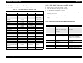
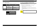
Consumables:
Developer Cartridge (black toner)
Photoconductor Unit (Drum Cartridge)
NOTE:
Noise
Table 1-21. Noise
Refer to “1.2.9 Consumable Components (p.32)”.
During standby
During printing
Sleep mode
30.0dB(A) *1
54.0dB(A)
Background noise
Main Unit only
Regular Replacement Parts
Without taking into account replacement by the user, the lives of regular
replacement parts are as follows:
Note “*1”: The fan runs at a half speed.
However, it runs at a full speed for 20 seconds after printing.
Fuser Unit:
50,000 pages
Transfer Roller: 50,000 pages
Exhaust Gas
Table 1-22. Exhaust Gas
Power Supply:
Gas
100 V ± 10%
50 ~ 60 Hz ±3 Hz
110 V - 10%
50 ~ 60 Hz ±3 Hz
127 V + 6%
50 ~ 60 Hz ±3 Hz
220 ~ 240 V ± 10%
50 ~ 60 Hz ±3 Hz
Applicable low-voltage power supplies are 100~120 V and 220~240 V only.
Value
Ozone Concentration
0.02 mg/m3 max.
Styrene Concentration
0.07 mg/m3 max.
Dust Concentration
0.15 mg/m3 max.
Note : By Blue Angel Mark measurement method
Power Consumption
Hazardous Materials:
None of the OPC, toner and plastics contains hazardous materials.
Table 1-20. Power Consumption
EPL-6200
Maximum current rated
EPL-6200L
100 V
12 0V
200 V
System
100 V
120 V
200 V
System
9.2 A
8.0 A
4.5 A
9.2 A
8.0 A
4.5 A
Power
Maximum
900 W 900 W 861 W 900 W 900 W 825 W
Consumption Average at continuous
376 Wh 370 Wh 372 W 378 Wh 372 Wh 357 W
printing
Average during
47 Wh
standby with heater on
44 Wh
48 Wh
47 Wh
46 Wh
48 Wh
Average during sleep
mode with heater off
6 Wh
7 Wh
7 Wh
7 Wh
8 Wh
7 Wh
Power off mode
0 Wh
0 Wh
0 Wh
0 Wh
0 Wh
0 Wh
NOTE: For safety standards, refer to “1.2.8 Compliance with Standards and
Regulations (p.31)”.
Current Consumption (EPL-6200)
Lower cassette:
5 V/ 0.03 A
Duplex Unit:
24 V/ 0.5 A
5 V/ 0.3 A
24 V/1.5 A
Product Lifetime
Main Unit
180,000 printed pages or 5 years, whichever comes first. (with periodic part
replacement) → See “ Consumable Components (p.32)”.
Product Description
Basic Specifications
25
EPSON EPL-6200/EPL-6200L
Revision A
1.2.3 Paper Specification
• Four-leaf printed postcard, postcards made for inkjet printing, or press
sealed postcards
• Iron print coated paper (for inkjet or laser printing)
• Sheets deteriorate or discolor by heat of the Fuser Unit of approximately
200°C.
1.2.3.1 Paper Type
Standard Paper
RX-80 paper: A4 / XEROX 4024 DP 20lb: Letter paper
Plain Paper
60 g/m2 ~ 90 g/m2 (16 lb ~ 24 lb)
generally applied copy paper, regenerated paper
1.2.3.2 Paper Feedings
Table 1-23. Paper Feedings
Special Applications
Labels
Transparencies
Thick paper (90 ~ 163 g/m2)
Envelopes
Special Applications
Standard Plain
Paper Paper Transparencies Labels Thick Envelope
paper
Standard Paper Tray
NOTE 1: lb: Ream weight = lb / 500 sheets/ 17” x 22” (431.8x558.8 mm)
g/m2: 1 g/m2 = 0.2659763 lb
2: The following types of paper should not be used with this printer.
They could cause printing defects, paper jams or printer malfunctions.
• Carbon paper, non-carbon paper, thermal paper, impact paper, acid-based
paper
• Paper that is too thin or too thick
• Paper that is wet or damp
• Paper with special coatings or colored paper with processed surfaces
• Too glossy (too slick on its surface) paper, or paper with too smooth/rough
surfaces
• Paper with significantly different roughness on each surface
• Paper with punch holes or perforations
• Creased, curled or torn paper
• Irregularly shaped paper or paper with non-perpendicular corners
• Labels that peel off easily
• Paper with glue, staples or paper clips attached to it
• Ink jet paper for special applications (super-fine, glossy, glossy film, etc.)
• Paper that was previously used in a thermal or ink jet printer
• Transparencies for color photocopiers or color laser printers
• Sheets already printed on other color / monochrome laser printers or
photocopiers
• Sheets of paper stuck together
Product Description
Optional
Lower
Cassette*
Duplex Unit *
{
∆
∆
∆
∆
{
{
×
×
×
×
×
×
×
×
Note “*”: Use of Lower Cassette and/or Duplex Unit is not supported with EPL-6200L.
{ : Paper feed reliability and image quality assured.
: Paper feed reliability and image quality assured, but only for the use of generally
applied types of paper.
∆ : Paper feed and printing are possible for only generally applied types of paper.
× : Sheets cannot be fed.
Basic Specifications
26
EPSON EPL-6200/EPL-6200L
Revision A
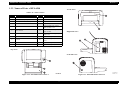
1.2.4 Reliability, Durability, Serviceability
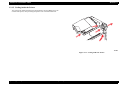
1.2.3.3 Printable Area
Available Printing Area:
1.2.4.1 Reliability
208.0mm × 348.0mm
MPBF
Guaranteed Printing Area:
All area of the sheet except vertical and horizontal margins of 4 mm (See
illustration below)
25,000 pages
NOTE:
MPBF means an average number of pages printed until the
occurrence of a malfunction which either requires the replacement
of parts or cannot be solved by the user.
MTBF:
3000 hours (ten months) or more
NOTE:
MTBF means an average period of time until the occurrence of a
malfunction which either requires the replacement of parts or
cannot be solved by the user.
Paper Feed Reliability
Table 1-24. Paper Feed Reliability
Guaranteed
Print Area
Error type
Paper-jam rate*1
Paper misfeed
Multiple-sheet feed
Figure 1-3. Guaranteed Print Area
rate*2
Environment
A
B
C
1/2000
2/2000
3/2000
1/2000
2/2000
3/2000
1/500
2/500
3/500
Paper creasing
1/1000
2/1000
3/1000
Leading edge folded*3
1/1000
2/1000
3/1000
Note “*1”: Includes paper jams caused by miss feeding, multiple-sheet feeding, and other kinds
of jam. Does not include paper jams caused by multiple-sheet feeding at the
boundary.
“*2”: Does not include multiple-sheet feed at the boundary.
Boundary means sheets boundary between original paper and replenished paper,
occurring after paper is replenished.
“*3”: Includes 1 mm or more corner fold, but does not include less than 1 mm corner fold.
NOTE 1: Based on use of paper taken from a newly opened package, that is, free from
curls and any deterioration.
2: This reliability also applies to 1200 dpi printing with EPL-6200.
3: This reliability applies to all the relevant paper feeders.
4: See “1.12 Ambient Conditions (p.64)”.
Product Description
Basic Specifications
27
EPSON EPL-6200/EPL-6200L
Revision A
Printing Start Position Accuracy
Skew
(With standard paper fed from Paper tray or Lower cassette)
Table 1-26. Skew
Table 1-25. Printing Start Position Accuracy
Scanning Direction
Simplex: A4
Duplex: A4
Simplex
Duplex
Main scanning direction |a-b|
±1.59 mm
±2.12 mm
Reference point of Main scanning direction (c)
±2.0 mm
±3.0 mm
Sub scanning direction |c-d|
±2.08 mm
±3.13 mm
Reference point of Sub scanning direction (a)
±2.5 mm
±3.0 mm
Measured based on the Dot 2 pattern.
Table 1-27. Skew
A4
Paper feeding direction
Printable area
Between a and b
195.580
Between c and d
282.575
NOTE: Specification values converted by the length of the Dot 2 pattern.
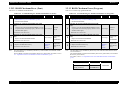
Height of Curl of Printed Pages
Table 1-28. Height of Curl of Printed Pages
Paper Size
Plain paper
±30 mm or less
Transparencies
±20 mm or less
Other special applications
Figure 1-4. Printing Start Position Accuracy
Height
Not specified
1.2.4.2 Durability
Printing Volume
Maximum 30,000 sheets / month
Average 2,500 sheets / month
1.2.4.3 Serviceability
MTTR
Averages within 30 minutes.
(Time for service personnel to locate and correct the malfunction)
Product Description
Basic Specifications
28
EPSON EPL-6200/EPL-6200L
Revision A
1.2.5 Operating Conditions (Including Consumables)
Upper value: EPL-6200
(Lower value): EPL-6200L
Ambient Temperature and Humidity Conditions
Table 1-29. Ambient Temperature and Humidity Conditions
Temperature (°C)
Humidity (%RH)
Printer is under operation
10 ∼ 35
15 ∼ 85
Printer is stopped
0 ∼ 35
10 ∼ 85
Others
No condensation
Barometric Pressure
76.0 to 101.0 kpa (Altitude: 0 ~ 2500 m)
Level
Differences between front and back, and left and right: within 1° of level
Lighting
3000 lx or less (do not expose to direct sunlight)
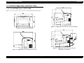
Space Requirements
In order to ensure that the printer operates properly, provide at least as much space
as shown in the figure below.
*1: 661 mm when Lower Cassette
Unit has been installed
<Duplex Unit has been installed>
Figure 1-5. Required Surrounding Space
Product Description
Basic Specifications
29
EPSON EPL-6200/EPL-6200L
Revision A
1.2.6 Storage and Transport of the Printer Main Unit and
Optional Products (Consumables Packaged)
Fast Transient / Bursts (AC Line Noise)
IEC 61000-4-4 compliance
Temperature and Humidity Conditions
Voltage 1 k: no malfunction occurs such as defective image quality.
2 kV: no damage to parts allowed.
Table 1-30. Temperature and Humidity Conditions
Temperature
(°C)
Humidity
(%RH)
Warranty Period
Normal
Conditions
0 ∼ 35
30 ∼ 85
18 months
Severe
Conditions
High temperature:
35 ∼ 40
Low temperature:
-20 ∼ 0
High humidity:
85 ∼ 95
Low humidity:
10 ∼ 30
1/30 of
warranty period.
Others
Instantaneous Outages
DIP 100% (at rated current - 10%) one cycle.
No effect on printing quality
No condensation
Transportation Barometric Pressure
61.3 ~ 101.3 kPa or more (460 ~ 760 mmHg)
Dropping
No abnormalities according to JIS Z0200-1998 Level 1
Vibration
Frequency:
Acceleration:
Direction of application:
Time of application:
1.2.7 Electrical Features
5 ~ 100Hz (Sweep time: 10 minutes)
1G
3 dimensional
60 minutes along each X, Y, Z axis,
180 minutes in total
Resistance to Static Electricity (IEC 61000-4-2 compliance)
Direct contact discharge: 4.5 kV
Indirect contact discharge: 4.5 kV
Aerial discharge:
8.5 kV
NOTE: Even when electric discharge as mentioned above occurs, the printer shall
keep operating normally without any trouble which affects the basic
performance or which can lead to breakdown of the printer.
Inrush Current: 50 A or less (0-peak)
Insulation Resistance: 10 MΩ or more (at DC 500 V)
Dielectric Strength
No break down during application of the voltages shown below for one minute.
Across primary and chassis
For 100 V models
AC 1000 V
For 110 to 127 V models
AC 1000 V
For 220 to 240 V models
AC 1500 V
Leak Current
Product Description
Basic Specifications
Intended Market
Leak Current
100 V (Japan)
0.25 mA or less
110 to 127 V models
3.5 mA or less
220 to 240 V models
3.5 mA or less
30
EPSON EPL-6200/EPL-6200L
Revision A
EMC
1.2.8 Compliance with Standards and Regulations
Safety Standards
Table 1-33.
Model Name
Table 1-31. Safety Standards
Model Name
100V
100V
Applicable Standards
110V-120V
IEC60950 (1998) compliant
110V-120V
UL60950 3rd (2000)
CSA-C22.2 No.60950-00 3rd
IEC60950 3rd (1999) + Country’s Differences in CB Bulletin
220V-240V
IEC60950 3rd (1999) + Country’s Differences in CB Bulletin
EN60950 (2000) + Annex ZB, ZC
GB4943-1995
For 200 V system models
Applicable Standards
VCCI Class B
FCC (47CFR) Part15 Subpart B Class B
ICES-003: Issue3 class B (C108.8-M1983)
EN 550222(1998) Class B
EN 61000-3-3+A1(2001) (Flicker)
EN 55024(1998) (Immunity)
CISPR 22 Class B
GB9254(1998) Class B
GB17625. 1-1998 Class A
Safety Standards (Laser Radiation)
Table 1-32. Safety Standards (Laser Radiation)
Model Name
100V
Applicable Standards
JIS C 6802+A1 (1998) compliant
110V-120V
FDA21CFR Chapter 1 Subchapter J, Part1040
IEC 60825-1+A1, 2 (2001)
220V-240V
EN 60825-1+A11, A2 (2001)
IEC 60825-1+A1, 2 (2001)
Note : <Only for Information>
Laser power (max.):
Wave length (average):
Max. Average Radiation Power at laser aperture:
Power on the OPC drum (max.):
Product Description
15 mW
785 nm
36.903 µW
1.044 µW
Electrical Harmonic Component
Complies with harmonic suppression guideline (JBMA)
EN61000-3-2 Class A(2000)
Electrical Power Consumption
Conforms to International Energy Star Program standards
Others
Toner:
OPC:
Ozone generation:
Materials:
Basic Specifications
Conforms to OSHA, TSCA, and EINECS
(No materials hazardous to human health)
Conforms to OSHA
(No materials hazardous to human health)
Blue Angel mark compliant
The materials do not contain any substances use of
which is prohibited by laws of the market countries,
and the contents of hazardous substances do not exceed
their respective allowable levels.
31
EPSON EPL-6200/EPL-6200L
Revision A
1.2.9 Consumable Components
1.2.9.2 Packing Storage and Transport Environments
Temperature and Humidity Conditions
1.2.9.1 Specifications
Table 1-35. Temperature and Humidity Conditions
Table 1-34. Consumable Specifications
Name
Contents
• Developer,
Developer
Toner hopper
Cartridge
•
Black,
single
(toner
component,
cartridge)
nonmagnetic toner
• OPC drum
Photocond (organic
uctor Unit photoconductor)
(Drum • Charger
Cartridge) (Rotary Brush +
Precharging Film)
Life*1
Size
(mm)
Pre-installed (EPL-6200):
3,000 sheets*2 on an
average
Pre-installed (EPL-6200L): (w) 275
1,500 sheets*2 on an
(D) 97
average
(H)
Replaced:
3,000 or 6,000 sheets *2 on
an average
20,000 sheets on an
average
(w) 292
(D) 155
(H) 91
Weight
(kg)
Initial
Filling
(g)
0.4
44.5 g
±5 g
0.4
85 g
±5 g
0.5
152 g
±5 g
0.5
-
Conditions
Humidity
Warranty Period
18 months
0 ∼ 35°C
30∼ 85%
High
35 ∼ 40°C
85 ∼ 95%
Low
-20 ∼ 0°C
10 ∼ 30%
Normal
Severe
Temperature
1/30 of warranty
period
Transportation Barometric Pressure
Conforms to the same requirements as for the main unit.
61.3 ~ 101.3 kPa or more (460 ~ 760 mmHg)
Dropping
No abnormalities according to JIS Z0200-1998 Level 1
Vibration
Frequency:
Acceleration:
Direction of application:
Time of application:
5 ~ 100Hz (Sweep time: 5 minutes)
1G
3 dimensional
60 minutes along each X, Y, Z axis,
180 minutes in total
Note “*1”: The number of sheets is the approximate number of printable images using A4
portrait continuous printing at 5% image occupation rate. The cartridge life varies
according to the image occupation rate and type of printing (continuous,
intermittent, printing density, and toner save mode).
“*2”: The external shape varies with the lives and intended markets.
Product Description
Basic Specifications
32
EPSON EPL-6200/EPL-6200L
Revision A
1.3 External Appearance and Parts Name
1.3.1 Overall Dimensions of EPL-6200
Figure 1-6 (p.33) to Figure 1-9 (p.33) show the overall dimensions of EPL-6200.
Figure 1-8. Right Side View with Lower Cassette installed
Figure 1-6. Front View of EPL-6200
Figure 1-7. Right Side View with Output Tray in Use
Product Description
External Appearance and Parts Name
Figure 1-9. Right Side View with Lower Cassette
and Duplex Unit installed
33
EPSON EPL-6200/EPL-6200L
Revision A
1.3.2 Overall Dimensions of EPL-6200L
Figure 1.3.1 (p.33) to Figure 1-11 (p.34) show the overall dimensions of EPL-6200L.
Figure 1-10. Right Side View with MP Tray and Output Tray in Use
Figure 1-11. Top View
Product Description
External Appearance and Parts Name
34
EPSON EPL-6200/EPL-6200L
Revision A
1.3.3 Names of Parts of EPL-6200
<Front View>
Table 1-36. Names of Parts
Symbol
1
Name
Symbol
Name
Control Panel
12
Parallel Interface Connector
2
Manual Feed Tray / Paper Guide
13
Duplex Unit Connector Cover
3
MP Tray / Manual Feed Tray
14
Output Cover
4
Front Cover
15
Output Tray
5
Paper Cassette Front Cover
16
Lower-cassette Unit (option)
Paper Cassette Cover
6
Power Switch
17
Lower-cassette Unit (option)
Paper Cassette
7
Optional RAM Cover
18
Lower-cassette Unit (option)
Feeder Unit
8
Duplex Unit Gear Cover
19
Duplex Unit (option)
9
AC Inlet
20
Duplex Unit (option) Connector
Cover
10
Type-B Interface Slot Cover
21
Duplex Unit (option) Cover 1
11
USB Interface Connector
22
Duplex Unit (option) Cover 2
<Right Side View>
<Top View>
<Left Side View>
Figure 1-13. EPL-6200 Names of Parts 2
Figure 1-12. EPL-6200 Names of Parts 1
Product Description
External Appearance and Parts Name
35
EPSON EPL-6200/EPL-6200L
Revision A
<View with Lower Cassette Unit installed>
<Rear View>
<View with Covers opened>
<View with Duplex Unit and Lower Cassette Unit installed>
Figure 1-15. EPL-6200 Names of Parts 4
Figure 1-14. EPL-6200 Names of Parts 3
Product Description
External Appearance and Parts Name
36
EPSON EPL-6200/EPL-6200L
Revision A
1.3.4 Names of Parts of EPL-6200L
Table 1-37. Names of Parts
Symbol
<Right Side View>
<Left Side View>
Name
1
Output Tray
2
LED
3
Front Cover
4
Paper Tray
5
Power Switch
6
Parallel I/F Connector
7
USB I/F Connector
8
AC Inlet
9
Output Cover
<Rear View>
<Top View>
<View with Covers opened>
<Front View>
Figure 1-16. EPL-6200L Names of Parts 1
Product Description
Figure 1-17. EPL-6200L Names of Parts 2
External Appearance and Parts Name
37
EPSON EPL-6200/EPL-6200L
Revision A
1.4 Controller Specification
EPL-6200L
CPU
1.4.1 Basic Controller Specifications
RAM
EPL-6200
CPU
EPSON 32bit RISC S1C33000 48MHz
TMPR4955BFG-200MHz (Same as for EPL-N2500)
RAM
<Standard>
8 MB (SDRAM) (mounted on ROM DIMM board)
<DIMM Option>
16 MB, 32 MB, 64 MB, 128 MB (SDRAM, 1 slot)
Maximum136 MB
(with 128 MB SDRAM DIMM installed)
<Standard>
2MB
<Expansion>
None
Interface
IEEE 1284 compatible parallel interface (ECP, Nibble)
USB
USB Revision 1.1 compatible, USB ID compatible
Panel
2 LEDs
Other expansion slots
None
ROM
<Fonts, Program>
Mixed in 16Mbyte (mounted on ROM DIMM board)
Flash memory by initial production; mask ROM by steady
production
<Expansion ROM>
None
Host Interface
<Standard>
Parallel
IEEE1284 compliant bi-directional interface, Type B
connector
Compatibility, Nibble, ECP
USB
USB Revision 1.1
Option
Type B slot (1 slot)
Control Panel
3 switches and 6 LEDs
Installation Format
Fixed to the printer body
Other
A mechanical control function is incorporated
Installed emulations
PCLXL, PCL5e, GL/2, FX, ESCP2, I239X, ESC/Page
PostScript 3
Product Description
Controller Specification
38
EPSON EPL-6200/EPL-6200L
Revision A
1.4.2 External I/F Specifications
1.4.2.1 Parallel Interface Specifications
EPL-6200/EPL-6200L is equipped with the external host interfaces as listed below:
Table 1-39. Parallel Interface Specifications
Table 1-38. External Host Interfaces
Standard
Optional
IEEE1284 parallel interface
USB interface (USB Revision 1.1)
Optional Type-B I/F Card slot
EPL-6200
EPL-6200L
{
{
{
{
{
–
Item
Description
Interface Type
IEEE 1284 bi-directional high speed parallel interface
Operating Modes
Compatibility, Nibble, ECP
Connector Model Names
57RE-40360-830B (D7A) DDK or equivalent products
Conforming Plugs
AMPHENOLE or equivalents
NOTE: Switching between host interfaces is automatic only. Each interface cannot
be switched on and off individually.
The initial Device ID value of this printer is described below:
EPL-6200
EPL-6200
Optional Type-B I/F Card slot
USB connector
MFG:EPSON;CMD:PJL,EJL,ESCPL2,ESCP9,PRPXL24-01,PCL,HPGL2-01,ESCPAGE04,PCLXL,POSTSCRIPT;
MDL:EPL-6200;
CLS:PRINTER;
DES:EPSON EPL-6200;
EPL-6200L
MFG:EPSON;CMD:ESCPAGES-02;MDL:EPL-6200L;CLS:PRINTER;DES:EPSON EPL-6200L;
Parallel I/F connector
EPL-6200L
Parallel I/F connector
USB connector
Figure 1-18. Rear View (Interface Bracket)
Product Description
Controller Specification
39
EPSON EPL-6200/EPL-6200L
Revision A
1.4.2.2 USB Interface
1.4.2.3 Type B Interface (Not Available with EPL-6200L)
Supports Windows USB PnP.
EPL-6200 is equipped with one Type-B option I/F slot as standard.
Supports the 18-digit USB ID as follows:
Main System Type:
MTP1200dpi, PW10200dt1200dpi, PRG(****)rev, AP500ma, SPD0fast, D4
**P++YYMMDDhhmmssR
**:
A number of 00 to 99. Acquired for each model.
“24” for EPL-6200. “23” for EPL-6200L.
P:
Identifier. Always “P” for page printers.
++:
PC number of assembly line. (00~99)
YY:
The year of assembled date. (lower two digits; 00~99)
MM:
The month of assembled date. (01~12)
DD:
The assembled date (01~31)
hh:
Hour of assembled time. (00~23)
mm:
Minute of assembled time. (00~59)
ss:
Second of assembled time. (00~59)
R:
Reserved and always “0” with EPL-6200/EPL-6200L.
NOTE:
Printer Name
:Factory default setting is the same as Product Name.
Product Name
: EPL-6200
Emulation Type / Entity Type
Table 1-40. Emulation Type / Entity Type
The USB ID written into the printer can be checked on the Status Sheet.
C A U T IO N
****: ROM version
Emulation
Emulation Type
Entity Type
PS
POSTSCRIPT-00
LaserWriter
ESC/Page
ESCPAGE-04
EPSONPAGE4
LJ4
PCL5E-00
EPSONPCL5
I239X
PRPXL24-01
EPSONPRPXL24
GL/2
HPGL2-01
EPSONHPGL2
FX
ESCP9
EPSONFX
ESCP2
ESCPL2
EPSONLQ2
PCLXL
PCLXL
EPSONPCLXL
If the circuit board is replaced, or other service performed, the USB
ID may be changed to another ID (this is because the USB ID is
rewritten when the EEPROM storing the USB ID is damaged or the
circuit board is replaced).In this case, if a printer with the USB ID
changed is connected to the PC, it is recognized as a different
printer, so the PC requires the USB port driver to be installed
again.
Product Description
Controller Specification
40
EPSON EPL-6200/EPL-6200L
Revision A
1.5 Control Panel (EPL-6200)
1.5.2 List of Settings
1.5.1 External Appearance and Names of Parts
This section describes setting items for EPL-6200.
The setting items are described in groups for each tab screen of the printer driver.
Values shown in bold and underlined characters are the factory default setting values.
Basic Settings
Table 1-42. Setting Items (Basic Settings)
1
Item
7
6
8
9
4
Dialog *1
Item
Setting Value
Paper Size
(Page size)
Orientation
Portrait, Landscape
Paper Source
MP Tray, Auto Selection, Lower Cassette *2
Paper Type *3
Unspecified, Plain, Letterhead, Recycled, Color,
Transparency, Labels, Thick Wide, Thick Narrow
(Resolution)
600 dpi, True 1200 dpi, Class 1200 dpi
None, Halftoning, EnhMG
2
5
Print Quality
Graphics *4
RIT *5
3
Toner Save
Figure 1-19. Control Panel of EPL-6200
Smooth ↔ Sharp
Light ↔ Dark
More Settings
ON, OFF
ON, OFF
Copies
(Number of copies to be printed)
Collate
ON, OFF
Note “*1”: Click the button on the tab screen to open a dialog box for further setting items.
“*2”: Added when Lower Cassette has been selected on Optional Settings
Table 1-41. Buttons and LEDs of EPL-6200
No.
1
2
3
4
5
6
7
8
9
Name
Information Switch
Ready LED
Data LED
Error LED
Start/Stop Switch
Job Cancel Switch
Memory LED
Toner LED
Paper LED
Product Description
Note
Color: Gray
Color: Green
Color: Yellow
Color: Red
Color: Pale green
Color: Brick red
Color: Red
Color: Red
Color: Red
“*3”: You can specify a paper kind only when Auto Selection has been selected by Paper
Source setting.
However, Duplex printing is not available with Transparency, Labels, Thick Wide
or Thick Narrow.
A paper type error occurs if the Paper Type setting does not agree with either of the
settings of MP Tray Paper Type and Cassette 1 Paper Type on Printer Settings.
"*4": “None” ....................... No graphics printing processing (no gray scale or
intermediate tone expression)
“Halftoning”............... Halftoning (gradation expression processing) will be
executed
“EnhMG” ................... EnhancedMicroGray function is used for gradation
expression processing. (Not available with 1200 dpi)
“*5”: Contour and shaded area of characters will be corrected. (Not available with 1200
dpi)
Control Panel (EPL-6200)
41
EPSON EPL-6200/EPL-6200L
Revision A
Layout
Printer Settings
Table 1-43. Setting Items (Layout)
Item
Dialog
*1
Table 1-46. Printer Settings
Item
Setting Value
ON/, OFF
Zoom Option
(When Zoom Option is
ON)
Output Paper
(Page size)
Zoom To
50 ~ 200% (in 1% increments)
Location
Upper Left, Center
Print Layout
ON, OFF
Rotate by 180
ON, OFF
ON, OFF
Duplex *2
(When Duplex is ON)
Binding
Left, Top, Right
Note “*1”: Click the button on the tab screen to open a dialog box for further setting items.
“*2”: Duplex printing is restricted to the paper sizes of A4, B5 and LT.
Special
Table 1-44. Setting Items (Special)
Dialog *1
Item
Item
Setting Value
Watermark
ON, OFF
Form Overlay
ON, OFF
Note “*1”: Click the button on the tab screen to open a dialog box for further setting items.
Optional Settings
Table 1-45. Setting Items (Optional Settings)
Item
Dialog *1
Item
Update the Printer Option Information Automatically
Update the Printer Option Information Manually
Installed Memory
Settings
Optional Paper Sources
Duplex Print Unit
Status Sheet
Setting Value
(See “Printer Settings” (p.42))
Extended Settings
(See “Extended Settings” (p.43))
Enable, Disable
Sleep Mode
MP Tray Paper Size
Time Out
Parallel I/F
Setting Value
A4, A5, B5, LT, HLT, LGL, EXE, GLG, GLT, F4, MON, C10, DL,
C5, IB5, C6
60 ~ 300 sec (in 10-sec steps)
Speed
Fast, Normal
Bi-D
ECP, Nibble, Off
Buffer Size
Normal, Maximum, Minimum
USB I/F
Buffer Size
Normal, Maximum, Minimum
AUX I/F
Buffer Size
Normal, Maximum, Minimum
Error Code
Ignore, Space
Page Protect
Auto ON
Toner Out Error
Stop, Continue
Auto Continue *1
ON, OFF
Avoid Error *2
ON, OFF
Dot Correction *3
ON, OFF
MP Tray Paper Type
(Paper kind)
Cassette 1 Paper Type
(Paper kind)
Reset OPC Level
OK / Cancel
Note “*1”: Selects whether to continue printing processing at occurrence of some error, such as
“Print Overrun”, “Paper Set”, “Mem Overflow” or “Duplex Mem Overflow”, by
releasing the printer from the error status automatically or to stop printing
processing.
ON: continue, OFF: stop (default)
“*2”: Selects whether or not to avoid the occurrence of “Print Overrun” error in ESC/
Page mode.
ON: avoid, OFF: does not avoid (default)
ON, OFF
ON, OFF
8, 24, 40, 72, 136
No Optional Paper Source, Lower Cassette
ON, OFF
–
Printer Settings
Item
“*3”: Selects whether or not to make compensation at printing of extreme fine lines
(equivalent to 1 dot) in 1200 dpi to prevent breaks in each line.
Invalid when [Graphic Mode] = “High Quality (PC)”
ON: Dot correction, OFF, No dot correction (default)
Note “*1”: Click the button on the tab screen to open a dialog box for further setting items.
Product Description
Control Panel (EPL-6200)
42
EPSON EPL-6200/EPL-6200L
Revision A
Extended Settings
Table 1-47. Extended Settings
Item
C A U T IO N
Setting Value
Graphic Mode *1
Do not disclose any hidden functions to users.
High Quality (Printer), High Quality (PC)
Print TrueType fonts as bitmap,
Print TrueType fonts with substitution
TrueType Font
Uses the settings specified on the printer,
Uses the settings specified on the driver
Front Top
Panel Settings
Offset
Front Left
-30 ~ 0 ~ +30 mm (in 0.5mm steps)
Back Top
-30 ~ 0 ~ +30 mm (in 0.5mm steps)
Back Left
-30 ~ 0 ~ +30 mm (in 0.5mm steps)
Density
1, 2, 3, 4, 5
Slip Blank Page
ON, OFF
Ignore the selected paper size
ON, OFF
High Speed Graphics Output
ON, OFF
Humidity
Normal, High
Feed Offset
[Hidden
Functions] *2
-30 ~ 0 ~ +30 mm (in 0.5mm steps)
Physical Offset *2
-3.5 ~ +3.5 mm (in 0.5mm steps)
Scan Offset
-3.5 ~ +3.5 mm (in 0.5mm steps)
Feed Offset2
-3.5 ~ +3.5 mm (in 0.5mm steps)
Scan Offset2
-3.5 ~ +3.5 mm (in 0.5mm steps)
Engine Status Sheet
Uses the spooling method provided by the operating system
–
ON, OFF
Note “*1”: Selects whether to perform printing processing on the PC side (“High Quality
(PC)”) or on the printer side (“High Quality (Printer)”).
“*2”: To display the setting dialog box for the hidden functions, click the “Extended
Settings” button on the “Optional Settings” page while holding down [ALT] +
[CTRL] + [Z] keys.
For details, see “1.6.4.2 Printer Adjustment (Hidden Function)” (p.55).
“*3”: Specify physical compensation values to adjust the paper feeding position.
Based on these values for Physical Offset, the Printing Area location is adjusted
according to the setting values for Offset in the Panel Settings on the “Extended
Settings” dialog box.
Product Description
Control Panel (EPL-6200)
43
EPSON EPL-6200/EPL-6200L
Revision A
1.5.3 Printer Messages
A list of printer messages with EPL-6200 is shown below.
Table 1-48. Printer Messages
Printer Status
Service Req effff *1
Service Req Eggg *2
Option RAM Error
ROM CHECK*3
RAM CHECK*3
Unable Clear Error*3
Self Test*3
Cancel All Print Job
Cancel Print Job
Jam X X X X *4
Install Imaging Cart
Image Cart ID Error
NonGenuine Toner
Image Cart R/W Error
Front Cover Open *5
Exit Cover Open *5
DuplexUpperCoverOpen *5
DuplexLowerCoverOpen *5
Manual Feed tttt
Can't Print Duplex
Paper Out sssss tttt
Replace Toner
Paper Set sssss tttt
Print Overrun
Mem Overflow
Duplex Mem Overflow
Invalid PS3
Invalid Aux I/F Card
Write Error ROM P*3
Writing ROM P*3
Reserve JobCanceled
Product Description
Status
EJL Status
Service call error
Service call error
Error
Status
Status
Status
Status
Status
Status
Error
Error
Error
Error
Error
LED Indications
Toner LED
Paper LED
On
On
Off
Off
Off
Off
Off
On
On
Off
Off
Off
Off
Off
Off
On
On
Off
On
Off
On
Off
On
Off
6000
6XXX
1003
1003
4234*4
4235
4237
4241
4238
Error LED
On
On
On
Off
Off
Off
Off
Blink 1
Blink 1
On
Off
Off
Blink 1
On
Memory LED
On
Off
On
Off
Off
On
Blink 1
Off
Off
Off
Off
Off
Off
Error
4239*5
On
Off
Off
Error
Error
Error
Error
Error
Error
Error
Error
Error
Error
Error
Status
Warning
1013
3005
4010
4236
3003
3000
3001
3004
4201
4014
4006
1005
2565
Blink 2
Blink 1
On
Blink 2
Blink 1
Blink 1
Blink 1
Blink 1
On
On
On
(Off)
Off
Off
Off
Off
Off
On
On
On
On
On
On
Blink 1
Off
Off
Off
On
Off
Off
Off
Off
Off
Off
Off
-
Control Panel (EPL-6200)
Ready LED
On
On
Off
Off
Off
Off
Off
Blink 1
Blink 1
Off
Off
Off
Off
Off
Data LED
On
On
Off
Off
Off
-
Off
Off
-
Blink 2
On
Blink 1
Off
Blink 1
Off
Off
Off
Off
Off
Off
-
Blink 2
Off
Off
Off
Off
Off
Off
Off
Off
Off
Off
Off
-
Blink 1
-
44
EPSON EPL-6200/EPL-6200L
Revision A
Table 1-48. Printer Messages (continued)
Printer Status
Can't Print
Collate disabled
Check Paper Size
Image Optimum
Check Paper Type
Need Memory
Form Feed *3
(Printing Status Sheet by panel operation)*3
Warming Up
Offline
Cancel Print Job (by host)
Toner Low
NonGenuine Toner
(Processing Job)*3
Sleep
Ready
(Printing)*3
(Communicate with non-active I/F)*3
Status
EJL Status
Warning
Warning
Warning
Warning
Warning
Warning
Status
Status
Status
Status
Status
Warning
Warning
Status
Status
Status
Status
Status
2072
2013
2004
2002
2008
2003
1008
1010
1006
1001
1003
2571
2571
1002
1007
1000
1009
1012
Error LED
(Off)
(Off)
(Off)
(Off)
(Off)
(Off)
(Off)
(Off)
(Off)
Blink 3
Blink 1
(Off)
(Off)
(Off)
(Off)
(Off)
-
Note “*1”: This pattern and the pattern of the engine error (service call) are alternately
displayed depending on the error details.
“*2”: This pattern and the pattern of the service call error are alternately displayed
depending on the error details.
“*3”: Must not be disclosed to users.
“*4”: XXXX means the appropriate one of the following four locations. If paper is
jammed at two or more locations, one of them is displayed in the following order of
priority.
Output, Printer, Feeder, Duplex
“*5”: Only one of these four cover open errors is indicated in the following order of
priority, even if two or more errors have occurred at the same time. (Only one is
displayed on the 20-digit LCD.) (Displayed characters TBD)
Front Cover Open, Output Cover Open, DuplexUpperCoverOpen,
DuplexLowerCoverOpen
Product Description
Memory LED
Blink 1
Blink 1
Blink 1
Blink 1
-
LED Indications
Toner LED
Paper LED
Blink 1
Blink 1
Blink 1
Blink 3
-
Ready LED
Blink 1
Off
Blink 1
Blink 3
On
-
Data LED
Blink 1
Blink 1
-
NOTE: In the table above, the items of Printer Status are listed in the order of
priority. (Upper items have higher priority)
• When an error and a warning occur simultaneously, a warning message does
not appear.
• When a warning occurs during occurrence of another warning, all the
corresponding LEDs flash.
• The “-” mark shows that the indication of the LED is independent of the
relevant printer status. This LED can flash or light up if a printer status of a
lower priority occurs.
C H E C K
P O IN T
Control Panel (EPL-6200)
Refer to 3.1.6 Printer Messages (EPL-6200) (p.102) for details of
service call errors.
45
EPSON EPL-6200/EPL-6200L
Revision A
1.5.4 Special Operation (EPL-6200)
With EPL-6200, the functions described below are activated by holding the specified
switches down when turning the printer on.
C A U T IO N
The functions other than Hexadecimal Dump and Photoconductor
Life Reset must not be disclosed to the user.
Error Related LED Indications
Size of received data is different from the specification:
Error LED flashing + Paper LED lighting
Mechanical Controller is not Flash:
Error LED flashing + Toner LED lighting
Model code of Mechanical Controller is different from that of the file:
Error LED flashing + Memory LED lighting
Some other error:
Error LED flashing
Error that can not be identified:
All LEDs flashing
Table 1-49. Special Operation
Function
Methods of operation
Hexadecimal dump
“Start/Stop” and power on *1
Photoconductor life reset
“Start/Stop” + “Information” and power on *1,*2
Initializing EEPROM
“Start/Stop” + “Job Cancel” + “Information” and power
on*1,*2
Initializing the panel setting value
“Job Cancel” and power on*1,*2
Program ROM update mode
“Job Cancel” + “Information” and power on*3
CPU reset
+ Printing of error sheet
Press the Information Switch at occurrence of a service
call error. An error sheet will be printed after warm boot.
Engine program ROM update mode “Start/Stop” + “Job Cancel” and power on*4
Note “*1”: The Ready LED and Error LED light up simultaneously when the printer
recognizes the function. Then all the LEDs go out once for one second or so.
“*2”: When the switches are released, the Ready LED and Error LED light up
simultaneously, and keep lighting during execution of the function.
“*3”: Release the switches when only the Ready LED starts flashing. (Other LEDs light
up)
The Ready LED flashes, while the Paper, Toner and Memory LEDs light up.
Upon completion of download, only the Ready LED flashes.
“*4”: Release the switches when only the Online LED starts flashing.
During data reception:
During data transfer to engine:
During other processing:
At writing end:
Product Description
Online LED lighting + Data LED flashing
slowly
Online LED lighting + Data LED flashing
+ Paper, Toner or Memory LED lights up
sequentially
Online LED lighting + Data LED flashing
Online LED flashing slowly + Error LED
lighting
Control Panel (EPL-6200)
46
EPSON EPL-6200/EPL-6200L
Revision A
1.6 Control Panel (EPL-6200L)
Meaning of LED Flashing on EPL-6200L
Table 1-51. Meaning of LED Flashing
1.6.1 External Appearance and Names of Parts
Ready LED Error LED
Supplement
Off
Off
-
Power off
On
Off
-
Ready to print (It include warning status)
Blink 1
Off
-
Blink 3
Off
-
Off
Blink 1
2
1
Blink 1
Blink 1
Blink 1
Blink 1
Green and red blink
alternately
Green and red blink
simultaneously
1. Green: On, Red: On
2. Green: Off, Red: Off
3. Green: Off, Red: On
4. Green: Off, Red: Off
5. Return to pattern 1
Blink 1 and
Off
Blink 1
On
Blink 1
-
Off
On
-
Blink 1
On
-
On
On
-
Figure 1-20. Control Panel of EPL-6200L
Table 1-50. Buttons and LEDs of EPL-6200L
No.
Name
Note
1
Ready LED
Color: Green
2
Error LED
Color: Red
Meaning
Moving to Ready status.
Warming up, receiving data is included.
Warning for consumables
Non genuine consumables warning
–
Engine Error
It is a service call error.
RAM check error (RAM is not installed.)
It is a service call error except or Engine
Error.
Ex) IPL Error
Recoverable Errors by Status Monitor.
Ex.) Underrun Error Replace paper error
Controller Error It is a service call error.
Ex.) Video Error
Data Expansion Error
EEPROM Access Error
Software Error
Protocol Error
It will be fixed after you turn it power off.
Recoverable Errors without power off.
Ex) Cover Open
Paper jam (Paper Out)
Note 1: The both two LEDs lights for a while when printer power turned on.
2: During Checking RAM Ready LED flash. (Interval time: On: 0.1sec Off: 0.1sec)
(But the time of checking RAM is very short, then the flashing may not visible.)
3: Interval time
Flashing1: On 0.3sec, Off 0.3sec
Flashing3: On 0.6sec, Off 2.4sec
Product Description
Control Panel (EPL-6200L)
47
EPSON EPL-6200/EPL-6200L
Revision A
Setting Items Requiring Administration by the Printer for each Printing or state
1.6.2 Printer Setting Items
change
A list of setting items for this printer is shown below.
Table 1-54. Function Setting (3)
Setting Items for which the Printer Stores the Changed Settings
Administrative
Table 1-52. Function Setting (1)
Setting item
Setting values
items Range of values
*Total Pages
0 ~ 99999999 pages
*Jam Counts
0 ~ 65534 times
Sleep Mode
ON, OFF *1
*Genuine Toner Change
0 ~ 254
Toner Out Error
Continue, Stop
*Non genuine Toner Change
0 ~ 254
Physical OffsetTop *2
-3.5 ~ 0 ~ 3.5 (mm) step 05.mm
*Toner Life counter
Physical Offset Left *2
-3.5 ~ 0 ~ 3.5 (mm) step 05.mm
0 ~ 100%
(Both 3K and 6K will reset to 100% by counter reset)
Humidity *2
Normal, High
*Photoconductor Life counter
0 ~ 100%
Note : Values shown in bold and underlined characters are the factory default setting
values.
Note “*1”: 15 minutes.
Setting Items that are Valid only in the Job, and are not be Stored in the Printer
Users can select setting items on the printer driver, and actual processing is performed
by the printer.
Table 1-53. Function Setting (2)
Paper Size
A4, A5, B5, LT, HLT, LGL, GLT, GLG, EXE, F4, MON,
C10, DL, C5, C6, IB5, User defined size
Interface mode of Parallel I/F
ECP, Nibble
*Registration position
(paper feed direction)
Note : The “*” means that those items are under control of EEPROM.
A4, A5, B5, LT, HLT, LGL, GLT, GLG, EXE, F4, MON, C10,
DL, C5, C6, IB5, User defined size
User defined size Width 76.2. ~ 216.0mm
Length 127.0 ~ 355.6mm
Copies
1 ~ 999
ON, OFF
Top Offset
-9 ~ 0 ~ 9 mm
Left Offset
-9 ~ 0 ~ 9 mm
Paper Type
Normal, Thick-Wide, Thick-Narrow Transparency
Density
1, 2, 3, 4, 5
Auto Continue
ON, OFF
Ignore Paper Size
ON, OFF
-5.98 ~ 5.98 mm step 0.46mm
CSIC items
C H E C K
P O IN T
Setting values
Toner Save
Product Description
MP Tray Paper Size
Firmware version
“*2”: These setting operations are not opened to users.
For setting method, see “Special Operation (EPL-6200L) (p.54)”.
Setting item
*USB ID
Control Panel (EPL-6200L)
Since character strings administrated in the printer do not exist,
names of setting items and setting values are described in names for
explanation. Consequently, these names do not match character
strings displayed in driver's user interfaces and the Status Sheet.
48
EPSON EPL-6200/EPL-6200L
Revision A
1.6.3 Status
Table 1-55. Printer Status (continued)
Status description
1.6.3.1 Status List
Items of printer status generated in this printer are listed below:
Table 1-55. Printer Status
Status description
Software Error
Status code
Ready LED
Error LED
6000
Off
On
Engine Error
6001 ~ 6008, 6014
Flash 1 *1
Flash 1 *1
Protocol Error
-
Flash 1
On
RAM Check Error
-
Flash 1
On
-
*1
Flash 1
Exiting Paper Jam
4012
Off
Flash
Paper Jam
4008
Off
Flash
Feed Jam (Paper Out)
4009
Off
Flash
Install Imaging Cart
4235
Off
Flash
IPL Error
Status code
Ready LED
Error LED
Sleep Mode
1007
On
Off
Ready
1000
On
Off
Printing Job
1009
Flash1
Off
Processing Job
1002
Flash1
Off
Non-active Interface
1012
-
-
Note “*”: For details of flashing patterns, refer to “Meaning of LED Flashing on EPL-6200L
(p.47)”.
Following status are listed in priority order. Above is higher
C H E C K
P O IN T
priority.
Refer to “3.1.6.1 Service Call Error (p.102)” for details of engine
errors.
Image Cart ID Error
4237
Off
Flash
NonGenuineToner Cart
4241
Off
Flash 1
1.6.3.2 Details of Status Messages and Processing
Image Cart R/W Error
4238
Off
Flash 1
Toner Out
4236
Off
Flash 1
Warming Up
Description
Front Cover Open
4002
Off
Flash
Exit Cover Open
4025
Off
Flash
Paper set Error
3003
Off
Flash 1
Invalid Paper Size
3002
Off
Flash 1
Print Underrun
3000
Off
Flash 1
Memory Overflow
3001
Off
Flash 1
Multi copy Error
2013
On
Off
Check Paper Size (warning)
2004
On
Off
The printer is warming up.
Processing
The printer becomes ready to print automatically after approximately eight
seconds.
(It takes approximately twenty one seconds for the printer to get ready after
power on.)
Printing Job
Description
Print Failure
2568
On
Off
Warming Up
1006
Flash
Off
Non-active Interface
Toner Low
2017
Flash 3
Off
Worn Photoconductor (5% or less)
2010
Flash 3
Off
Description
NonGenuineTonerCart (warning)
2571
Flash3
Off
Product Description
The printer is printing.
The printer is processing a job through another interface.
At this moment, your computer can not send data to printer.
Control Panel (EPL-6200L)
49
EPSON EPL-6200/EPL-6200L
Revision A
Processing
1.6.3.3 Details of Error Status and Processing
The printing will start automatically after completion of the current job.
Processing Job
Description
The printer is processing a print job
Sleep mode
Description
The printer is in sleep mode.
Processing
The printer becomes ready to print after receiving printing data.
Ready
Description
The printer is ready to print (normal status).
Exiting Paper Jam
Description
A paper jam has occurred around the paper ejecting area.
The error is cleared when there is no longer any paper jam detected.
After error recovery, data for one page retained in the printer memory are
recovered if it is possible, and if the data cannot be recovered, the printer
returns a resending request. The data is recovered when the printer does not
perform a flying start. Cleaning is executed after the error recovery.
NOTE:
The printer displays an Exiting Paper Jam status if the Output
Cover is open at power on.
Remedy
Remove the jammed paper, close the Output Cover and close the front cover.
Then printing resumes from the jammed page.
The pop-up display of the EPSON Status Monitor disappears after error
recovery.
Paper Jam
Description
A paper jam occurrence inside of the printer.
The error is cleared when there is no longer any paper jam detected.
After error recovery, data for one page retained in the printer memory are
recovered if it is possible, and if the data cannot be recovered, the printer
returns a resending request. The data is recovered when the printer does not
perform a flying start. Cleaning is executed after the error recovery
Remedy
Remove the jammed paper and close the front cover. Printing resumes from
the jammed page.
The pop-up display of the EPSON Status Monitor disappears after error
recovery.
Product Description
Control Panel (EPL-6200L)
50
EPSON EPL-6200/EPL-6200L
Revision A
Feed Jam (Paper Out)
Description
NonGenuineToner Cart
Description
No paper has been fed even though printer has started printing action.
The error is cleared when there is no longer any paper jam detected after
opening and closing the front cover.
After error recovery, data for one page retained in the printer memory are
recovered if it is possible, and if the data cannot be recovered, the printer
returns a resending request. The data is recovered when the printer does not
perform a flying start. Cleaning is not executed after the error recovery.
Remedy
If there is no paper, set paper and open and close the front cover. In the case of
a jam, remove the jammed paper which was not fed and open and close the
front cover. Then printing resumes from the jammed page. The pop-up
display of the EPSON Status Monitor disappears after error recovery.
The error can be cleared through the Status Monitor even without opening and
closing the cover.
Install Imaging Cart
Description
The Imaging Cartridge is not set or not set correctly. The error is cleared when
the Imaging Cartridge is detected.
(When no CSIC is found, the error occurs.)
Remedy
Open the cover, set the Imaging Cartridge properly and close the cover again
to clear the error. The pop-up display of the EPSON Status Monitor
disappears after error recovery.
5)Imaging cartridge ID error
Description
The Developer Cartridge is not for this printer or the cartridge is broken.
This error will occur when the printer judges the Developer Cartridge is not
the appropriate EPSON worldwide model with a capacity of 3k or 1.5K.
Remedy
Open the cover, set the correct Developer Cartridge and close the cover again
to clear the error. The pop-up display of the EPSON Status Monitor
disappears after error recovery.
Product Description
The installed Developer Cartridge (toner cartridge) is judged to be not
EPSON genuine.
CAUSE 1. The manufacture ID is not the ID of EPSON.
2. The toner counter has been returned.
Remedy
Open the cover, set the correct Developer Cartridge (toner cartridge) and
close the cover again to clear the error. The pop-up display of the EPSON
Status Monitor disappears after error recovery.
If user want to use the non genuine cartridge, select [Continue] on the EPSON
Status Monitor.
After select [Continue], NonGenuineTonerCart warning occurs.
Image Cart R/W Error
Description
Normal access to the CSIC of the Developer Cartridge is impossible.
This error will be cleared when it is detected that a Developer Cartridge with a
normal CSIC has been set.
Remedy
Open the cover, set the correct Developer Cartridge and close the cover again
to clear the error. The pop-up display of the EPSON Status Monitor
disappears after error recovery.
Toner Out
Description
The toner life counter has reached the end of its service life (0%).
When the consumables expire while printing is underway, the operation stops
before the next page is printed. This error occurs only when Toner Out Error =
STOP.
Remedy
Replacing the Developer Cartridge (toner cartridge) with a new one clears the
error, and the pop-up message of the EPSON Status Monitor disappears.
NOTE:
Control Panel (EPL-6200L)
If you change the Toner Out Error = Continue, then the status
becomes Toner Low and you can print again.
51
EPSON EPL-6200/EPL-6200L
Revision A
Front Cover Open
Description
Invalid Size
Description
Font printer cover is open.
This error is cleared when the cover is not detected to be open any longer.
Remedy
When the cover is closed, the error is cleared, and the pop-up display of the
EPSON Status Monitor disappears accordingly.
Exit Cover Open
Description
Remedy
Output Cover is open.
This error is cleared when the cover is not detected to be open any longer.
NOTE:
Since an unsupported paper size was specified or a different feeding direction,
such as A4 Long Edge Feed, was selected, operation stopped before printing.
The Continue command of the ESCPAGES-02 protocol clears the error, and
printing resumes from the next page. When “Auto Continue = ON” this error
dose not occur and the page is printout.
Printing will be achieved if the printer driver can clip the image to A4.
Therefore, this error will not occur when you use a proper printer driver.
The printer displays an Exiting Paper Jam status if the Output
Cover is open at power on.
Remedy
When the cover is closed, the errors disappear, and the pop-up display of the
EPSON Status Monitor disappears accordingly.
Paper Set
Description
Since the paper size specified by Paper Size setting differs from the paper size
recognized by the size detected by printer itself, operation stops before
printing.
The Continue command of the ESCPAGES-02 protocol clears the error in the
printer engine, and the error in the printer is cleared accordingly. The
ResetPrinter command releases the error in the printer engine resetting the
printer to the initial status.
This error does not occur when the specified paper size is an undefined paper
size, and when “Size Ignore = ON” or “Auto Continue=ON” is selected. This
error occurs only once in one document.
Remedy
Insert appropriate paper, and select [Continue] on the EPSON Status Monitor.
To reprint after modifying driver settings, select [Cancel Printing] on the
EPSON Status Monitor.
To print pages after “Invalid Size”, select [Continue] on the EPSON Status
Monitor.
To reprint after modifying driver settings, select [Cancel Printing] on the
EPSON Status Monitor.
Print Underrun
Description
Data was not sent from the host during processing of a document and time-out
occurred. Then printing began, but the band data is insufficient. Resetting the
printer to the initial status by the ResetPrinter command of the ESCPAGES02 protocol clears the error.
When “Auto Continue = ON” is set and printer can not printout the page
“Print Failure” is displayed instead of the error, and resumes printing the next
page.
This error does not occur when “Auto Continue=ON” or “Avoid Page Error =
ON” is selected.
Remedy
If data receiving is not completed, selecting [Reprint] on the EPSON Status
Monitor performs printing successfully in some cases, as a result that the
printer driver resends data without a flying start.
To reprint after modifying driver settings, select [Cancel Printing] on the
EPSON Status Monitor.
Mem Overflow
Description
Printing was not successful since the data for one page was not saved due to
insufficient memory at printing operation without flying-start or printing was
not successful because of insufficient memory at a flying start resulting from
Product Description
Control Panel (EPL-6200L)
52
EPSON EPL-6200/EPL-6200L
Revision A
“Near Buffer Full”. The Continue command of the ESCPAGES-02 protocol
releases the error, and printing resumes from the next page. When “Auto
Continue = ON”, the printer displays the “Print Failure” warning instead of
this error, and resumes printing the next page.
Regarding the following envelopes, the paper size for this check is
extended by 5 cm as the flap:
Yokei0, Yokei4, Yokei6, Yokei 3, Chokei4, Chokei3, MON, C10, DL, C5,
C6, IB5
Remedy
Remedy
To print pages after “Mem Overflow”, select [Continue] on the EPSON Status
Monitor.
To reprint after modifying driver settings, select [Cancel Printing] on the
EPSON Status Monitor.
This warning appears when “Auto Continue=ON” and any of the following
conditions has occurred in the printer.
Multi Copy Error
Description
Band data of the page for multi-copying has not been saved for one page
completely.
This warning is cleared by the ResetFlag command of the ESCPAGES-02
protocol.
This warning status occurs before completing sending data for one page in
some cases, however continuing to send the data prints only one sheet.
Remedy
This warning occurs only at printing operation by a flying start. After
occurrence of this warning, however, data are resent “the number of copies n 1" times from the printer driver, so that this warning status is not displayed on
the user interface.
Check Paper Size
Description
The paper size that was actually fed differed from the paper size recognized
by the paper size detected by printer itself.
This warning is cleared by the ResetFlag command of the ESCPAGES-02
protocol.
This warning does not occur when the specified paper size is an undefined
paper size, and when “Size Ignore = ON” is selected.
The warning does not occur in the following situation:.
The printer is shared by some PCs and printer changes the control PC
before occurrence of warning on the previous PC.
Product Description
Clicking the [Close] button closes the pop-up display of the EPSON Status
Monitor. However, if an error of higher priority occurs just after that, the
display changes to the error display. From this point the status is never
displayed until it occurs again.
Print Failure
Description
1.6.3.4 Details of Warning Status and Processing
NOTE 1:
2:
• Memory Overflow
• Printer could not printout a page due to Print Underrun
This warning is cleared by the ResetFlag command of the ESCPAGES-02
protocol.
Remedy
Clicking the [Close] button closes the pop-up display of the EPSON Status
Monitor. However, if an error of higher priority occurs just after that, the
display changes to the error display. From this point the status is never
displayed until it occurs again.
NOTE:
Check Paper Size
The warning does not occur in the following situation:.
The printer is shared by some PCs and printer changes the control
PC before occurrence of warning on the previous PC.
Toner Low
Description
Toner Cartridge life counter is 10% or less of 3000-sheet capacity Developer
Cartridge.
It occurs even if the level is 0% in case of the Toner Out Error = Continue.
Remedy
Clicking the [Close] button once closes the pop-up display of the EPSON
Status Monitor. However, it will be displayed again if the warning is still
remain after changing another status.
Control Panel (EPL-6200L)
53
EPSON EPL-6200/EPL-6200L
Revision A
When you replace the Developer Cartridge (toner cartridge), the pop-up
message of the EPSON Status Monitor disappears.
(The toner counter reset can be executed even if you do not replace the
Developer Cartridge.)
Worn Photoconductor
Description
1.6.4 Special Operation (EPL-6200L)
This section describes the special operation functions of EPL-6200L.
C A U T IO N
This function, a hidden function, must not be opened to users.
Photoconductor life is 5% or less.
Remedy
Clicking the [Close] button once closes the pop-up display of the EPSON
Status Monitor. However, it will be displayed again if the warning is still
remain after changing another status.
Replace the Photoconductor Unit and reset the counter by printer driver. As a
result, the pop-up message of the EPSON Status Monitor disappears. (The
Photoconductor reset can be executed even if you do not replace the
Photoconductor Unit.)
NonGenuineTonerCart
Description
Installed Developer Cartridge (toner cartridge) is not EPSON genuine.
Remedy
Open the cover, set the correct Developer Cartridge (toner cartridge) and
close the cover again to clear the error. The pop-up display of the EPSON
Status Monitor disappears after error recovery.
However, it will be displayed again if the warning is still remain after
changing another status.
Product Description
1.6.4.1 EEPROM Initialization
The setting values in the printer are cleared. The following items are initialized:
Total Pages
Jam Count
Genuine Toner Change
Toner Life counter (CSIC)
Photoreceptor Life counter
USB ID
Registration position (paper feed direction)
Non Genuine Toner Change
A D J U S T M E N T
R E Q U IR E D
Control Panel (EPL-6200L)
After EEPROM initialization, input the USB ID and make the
registration adjustment.
For details, refer to “5.3 Feed Registration Adjustment (p.169)”.
54
EPSON EPL-6200/EPL-6200L
Revision A
HOW TO INITIALIZE EEPROM
1.6.4.2 Printer Adjustment (Hidden Function)
1.
Open the “Optional Settings” of the printer driver property.
For the following setting items for which the printer stores the settings, you can change
the setting by the following procedures:
2.
While pressing the [ALT] + [CTRL] + [SHIFT] + “W” keys together on the keyboard
of the personal computer, click any point in the blank area on the screen.
Humidity:
3.
On the dialog screen for confirmation, click “Yes” to execute EEPROM initialization.
Use this function to change the transfer voltage when the printing density drops in
a high humidity environment.
For details, see “1.10.3 About the Moist Environment Mode Select (p.60)”.
Physical Offset:
Adjusts the physical position on the paper where the print begins. (Default: 0)
SETTING PROCEDURE
1.
Open the “Optional Settings” of the printer driver property.
2.
While pressing the [CTRL] + [SHIFT] + [Z] keys together on the keyboard of the
personal computer, click the “Extended Settings” button of “Printer Driver”.
Click here while pressing [ALT] +
[CTRL] + [SHIFT] + “W”
Click here while pressing
[CTRL] + [SHIFT] + “Z”
Click “Yes” to execute EEPROM initialization
Figure 1-21. EEPROM Initialization
Product Description
Figure 1-22. Printer Adjustment Menu
Control Panel (EPL-6200L)
55
EPSON EPL-6200/EPL-6200L
Revision A
3.
On the screen of the printer adjustment window (hidden window), change the setting
value for the appropriate item.
4.
After changing the setting value, click the [Execute] button of the printer driver to
finalize the setting.
Figure 1-23. Printer Adjustment Window
Product Description
Control Panel (EPL-6200L)
56
EPSON EPL-6200/EPL-6200L
Revision A
1.7 RAM Expansion
1.8 System Requirements (Only for EPL-6200L)
When EPL-6200 runs out of memory, the Memory LED flashes or lights up.
In this case, you have to mount expanded RAM (RAM DIMM).
The minimum system configuration and recommended system configuration when
using EPL-6200L are shown in Figure 1-56 (p.57) and Figure 1-57 (p.57).
This problem may be solved by taking appropriate ones of the following measures:
Table 1-56. Windows
Reducing the resolution.
Select “Halftone” when using Enhanced MicroGray.
Reducing the receiving buffer size to “Minimum”.
Use only one interface and set “Off” for other interfaces.
The only way to definitely avoid memory shortages is to install more memory.
(Commercially available SDRAM DIMM for PCs: 90 pins, 32-bit without SPD)
C H E C K
P O IN T
With EPL-6200L, RAM cannot be expanded (fized to standard
RAM size : 2MB).
However, EPL-6200L can print most types of print job with the
standard RAM; by employing a high efficiency data compression
algorithm and a hardware accelerated data expansion function.
Windows
Minimum *1
Recommended *1
CPU
Pentium
←
Clock
133MHz
233MHz or more
Memory
16MB
64MB or more
Interface
IEEE1284 Parallel
Standard USB *2
←
OS
Windows 95/98/Me/XP
Windows NT 4.0
Windows 2000
←
Note “*1”: Exception: The requirement given here does not apply to the case where the
minimum configuration required by each OS or application is higher than specified
above.
“*2”: Limited to PC's who support the USB as standard equipment. Operation is not
guaranteed with a USB port installed in an expansion slot. Connection through a
device that switches the interface, such as a Parallel - USB converter, is not covered
by the warranty. When connecting through a USB port, operation under Windows
95 is not covered by the warranty.
Table 1-57. Mac
Product Description
RAM Expansion
Mac
Minimum
Recommended
Machine
Power Mac G3 with
standard USB
or
iMac
iBook
←
Clock
233MHz
←
Memory
32MB
64MB
Interface
Standard USB
←
OS
Mac OS 8.6 or later, 9.X, 10.1.2 or later
←
57
EPSON EPL-6200/EPL-6200L
Revision A
1.9 Paper Feed Specifications (Only for EPL-6200L)
1.9.1 Paper Size
1.9.2 Paper Feed Specifications
The following three types of information related to paper sizes are available.
User setting size:
Paper sizes that the user specifies on the printer driver.
<Supported paper sizes>
A4, A5, B5, LT, HLT, LGL, GLT, GLG, EXE, F4, MON, C10, DL, C5, C6,
IB5, User defined size
Printer paper size:
Paper sizes for the MP Tray that the printer recognizes is stored
in EEPROM.
MP Tray paper size:
A size of paper that is loaded in the MP Tray and is actually
fed.
The Printer paper size is changed or determined as follows.
Items
Specifications
Methods of detecting
the Paper Set error
The printer detects the error when the Printer paper size differs from
the User setting size (red LED blinks). However, this error does not
occur if the User setting size is other than standard sizes (User
defined size) or the Printer paper size is undefined.
Methods of detecting
the Check Paper Size
(warning)
The printer detects the error when the User setting size differs from
the MP Tray paper size. However, when the User setting size is
other than standard sizes (User defined size), this error is not
detected. Other exceptions: see Check Paper Size of “Details of
Warning Status and Processing” (p.53).
NOTE: Refer to “1.9.3 Case List (p.59)”
When the power to the printer is turned on:
Undefined.
After ejecting paper:
Table 1-58. Paper Feed Specifications
In the case where the User setting size is a standard size
When the Check Paper Size error does not occur
→ User setting size.
When the Check Paper Size error occurs → Undefined.
In the case where User setting size is User defined size:
No modification is added to the paper size.
Product Description
Paper Feed Specifications (Only for EPL-6200L)
58
EPSON EPL-6200/EPL-6200L
Revision A
1.9.3 Case List
The table below shows a case list of paper feed specifications for each paper size.
Table 1-59. Case List
User setting size A
Printer paper size B
User defined size
Standard
Undefined
Standard paper size
-
A=B
A not = B
A=C
Paper Set error
Check Paper Size error
Printer paper size after printing
Does not occur
Does not occur
B: No resizing
Does not occur
Does not occur
Undefined (no resizing)
(B = C)
Does not occur
Does not occur
B: No resizing
(B not = C)
Occurs
Does not occur
A
-
Undefined
-
Does not occur
Does not occur
Undefined (no resizing)
A=B
(B not = C)
Does not occur
Occurs
Undefined
B=C
Occurs
Occurs
Undefined
B not = C
Occurs
Occurs
Undefined
-
Does not occur
Occurs
Undefined
A not = B
Undefined
NOTE 1:
2:
3:
4:
5:
MP Tray paper size C Relation between B and C
A not = C
“-” means “Don't care”.
The User setting size (A) and the Printer paper size (B) determine whether the Paper Set error occurs or not.
The User setting size (A) and the MP Tray paper size (C) determine whether the Check Paper Size error occurs or not.
Differences between the Printer paper size (B) and the MP Tray paper size (C) do not influence each error occurrence.
Other exceptions: See Check Paper Size of “Details of Warning Status and Processing (p.53)”.
1.9.4 Special Notes
When the User defined size is specified for the User setting size, the Check Paper Size error does not occur.
When the Printer paper size is undefined, the Check Paper Size error occurs in some cases.
Product Description
Paper Feed Specifications (Only for EPL-6200L)
59
EPSON EPL-6200/EPL-6200L
Revision A
1.10 Notes on Operation
1.10.3 About the Moist Environment Mode Select
1.10.1 Power Off (EPL-6200)
This is a switch that operates to lower the print density in a high humidity environment.
Ordinarily it does not operate.
EPL-6200 incorporates an internal non-volatile memory (EEPROM).
If the power to the printer is turned off during the process of writing in non-volatile
memory, the successful writing in the non-volatile memory cannot be guaranteed.
Therefore, the next time the printer is turned on, panel settings may be initialized or a
service call error may occur.
The non-volatile memory saves the function settings, and the following cases are those
in which the memory is rewritten, and therefore the printer should not be powered off:
Use this switch only in cases where the above special environmental conditions exist.
When the use environment returns to normal environmental conditions, it is necessary
to return it to the original setting immediately.
SETTING PROCEDURE
1.
Open the printer driver on the personal computer.
After the printer is powered on, until the Ready LED lights up.
While the printer is printing.
2.
Open the “Optional Settings” page.
(While the paper feed motor is operating.)
While the Data LED is flashing or lit.
To stop the printer, either put it off line or carry out All Print Job Data Cancel.
3.
Click the “Extended Settings” button while holding down [ALT] + [CTRL] + [Z] keys.
NOTE: For details, see “1.6.4 Special Operation (EPL-6200L) (p.54)”.
1.10.2 Caution About Hot Parts (EPL-6200/EPL-6200L)
C A U T IO N
where no other measure hardly can cope with the problem
since the user environment is highly humid.
The fuser unit inside the printer is heated to high temperatures, once the printer cover is
opened to clear paper jam or for some reasons, take care not to touch the fuser unit.
C H E C K
P O IN T
Product Description
This function, a hidden function, must not be opened to users.
This setting can be made by a serviceman in specific cases
Notes on Operation
Print quality is not guaranteed if the printer is used with the highhumidity environment setting in normal environment.
60
EPSON EPL-6200/EPL-6200L
Revision A
1.11 Status Sheet
<EPL-6200>
A sample of the Status Sheet is shown at right.
The following information is printed at bottom left in the order of 1) to 8):
1). IA followed by firmware version shown in the DDYM format
For M (month), “A” represents October, “B” November and “C” December
2). Negotiation result of IEEE1284
e: ECP, n: Nibble, or none: Compatibility or not connected
3). Device type of code ROM
*: Flash or none: Mask
4). 6-digit number indicating the number of times a jam has occurred
JXXXXXX
5). The number of times the Developer Cartridge (toner cartridge) was replaced:
“ICXXX YYY”
The number of digits depends on the replacement count.
X: The number of times the genuine Developer Cartridge (toner cartridge)
was replaced with a new one. Counting is continued until a maximum of
999 new cartridges are installed. The Developer Cartridge that has been
installed in any printer once is not regarded to be a new one even if it has
never been used for printing.
Y: The number of times the non-genuine Developer Cartridge was replaced
with a new one.
6). USB ID (24PXXXXXXXXXXXXXXX)
7). The latest connection status of USB communicate mode
F: FS, or none: no connection with USB
8). 10-digit number headed by MC, representing the Mechanical Controller
version of the engine
Product Description
Status Sheet
61
EPSON EPL-6200/EPL-6200L
Revision A
Notes on the status sheet (a sample) for EPL-6200 are as follows:
Note “*1”: Printed only when the relevant optional unit has been installed.
“*2”: “Needed Soon” will be shown when the amount of toner remaining is supposed to
permit printing for not more than 300 sheets.
“*3”: “Needed Soon” will be shown when photoconductor life is 5% or less.
“*4”: The following notice is given when non-genuine Developer Cartridge (toner
cartridge) has been installed:
Non-genuine cartridge installed.
Using a non-genuine cartridge may affect
print quality.
Genuine EPSON cartridge recommended.
“*5”: Names and Part Numbers of consumables indicated at Information:
Nme of Consumable
Part Numbers
Developer Cartridge
S050166/S050167
Note) S050166: 6K, S050167: 3K
Photoconductor Unit
S051099
Product Description
Status Sheet
62
EPSON EPL-6200/EPL-6200L
Revision A
<EPL-6200L>
A sample of the Status Sheet is shown at right.
The following information is printed at bottom left.
NOTE: A space is put in each item.
IAXXXX
Controller firmware date. XXXX=ddym
About the m (month), they are shown as below.
Oct. is A, Nov. is B and Dec. is C.
JXXXXX
Jam counter (the number of digits is five)
ICX Y
X: Counter of changing of Developer Cartridge (toner
cartridge).
Y: Counter of changing of non-genuine Developer
Cartridge (The number of digits depends on the count.)
MCXXXXXX
Engine Firmware version
23PXXXXXXXXXXXXXX USB ID
Notes on the status sheet (a sample) shown at right are as follows:
Note “*1”: “Needed Soon” will be shown when toner counter is 10% or less of 3,000-sheet
capacity.
“*2”: “Needed Soon” will be shown when photoconductor life is 5% or less.
“*3”: The following notice is given when non-genuine Developer Cartridge (toner
cartridge) has been installed:
Non-genuine cartridge installed. Using a non-genuine cartridge may affect
print quality.
Genuine EPSON cartridge recommended.
NOTE 1: Developer Cartridge (toner cartridge) model and toner capacity:
S050167: 3K
2: Photoconductor Unit model: S051099
3: Toner remaining amount at 6 levels, Photoconductor life at 6 levels
Product Description
Status Sheet
63
EPSON EPL-6200/EPL-6200L
Revision A
1.12 Ambient Conditions
ENGINE STATUS SHEET (EPL-6200)
Printing Procedure:
The ambient conditions to ensure the performance of EPL-6200/EPL-6200L are as
follows:
1.
Open the printer driver on the personal computer.
2.
Open the “Optional Settings” page.
3.
Click the “Extended Settings” button while holding down [ALT] + [CTRL] + [Z] keys.
C H E C K
P O IN T
This function, a hidden function, must not be opened to users.
Environment A:
Range of ambient conditions to guarantee image quality and paper
feed
Environment B:
Range of ambient conditions to guarantee paper feed
Environment C:
Range of ambient conditions to guarantee paper feed
Environment X:
Range of ambient conditions to guarantee operation
Humidity(%)
85
C
Shown below is an example of the engine status sheet of EPL-6200:
X
70
65
A
Feed Offset
Scan Offset
Feed Offset2
Scan Offset2
Humidity
Feed Regist
0.0
0.0
0.0
0.0
0
0.0
35
mm
mm
mm
mm
B
15
mm
0
Temperature (°C)
10 15
25 30 35
Figure 1-25. Temperature and Humidity Environment
Figure 1-24. Print Sample of Engine Status Sheet
NOTE 1: The Engine Status Sheet is not localized.
2: Each numeric value shown in the example is the upper limit of counting.
3: All the values indicated are those that have been set with EJL and stored in
EEPROM.
Product Description
Ambient Conditions
64
EPSON EPL-6200/EPL-6200L
Revision A
1.13 Differences in Specifications between Intended Markets
1.13.1 Differences in Specifications
Table 1-60. Differences in Specifications between Intended Markets
Model
EPL-6200
Intended Markets
Resolution /Printing
Speed
South
America
and
Taiwan
EPL-6200L
LP-1400
Japan
South
America Europe, Pacific, China and
and
Korea
Taiwan
Japan
←
600 dpi: 20 ppm
←
Europe, Pacific, China and
Korea
1200 dpi: 10 ppm, 600/300 dpi: 20 ppm
Pre-installed: 3000 sheets
Replaced: 3000 sheets or 6000 sheets
Toner Life
LP-2500
Standard RAM
RAM Expansion
Optional ROM Slot
Type-B Slot
Control Panel
Main Board Assy
Pre-installed: 1500 sheets
Replaced:
6000 sheets
Pre-installed: 1500 sheets
Replaced:
3000 sheets or 6000
sheets
←
8 MB
16 MB
2 MB
←
136 MB max.
144 MB
None
←
1 slot (for PS or IPDS option)
None
None
←
Supported
←
None
←
3 SW/ 6 LEDs
←
2LEDs
←
C533MAIN
(WW spec)
C533MAIN
(J spec)
C534MAIN
(WW spec)
C534MAIN
(J spec)
Memory Board Assy
• C533PROG (WW spec) (initial products)
• C533PROG-C (WW spec) (by stable
production)
• C533PROG (J spec) (initial products)
• C533PROG-B (J spec) (by stable production)
-
-
Optional Units
• Lower Cassette Unit
• Duplex Unit (Lower cassette required)
• Lower Cassette Unit
-
-
Power Supply Unit
C H E C K
P O IN T
120V
system
220V system
100V system
120V
system
220V system
100V system
There is a difference in jumper setting between “WW spec” and “J
spec” of C533MAIN/C534MAIN. Refer to “Jumper Setting” (p.66).
Product Description
Differences in Specifications between Intended Markets
65
EPSON EPL-6200/EPL-6200L
Revision A
1.14 Notes on Installation of Optional Units
1.13.2 Jumper Setting
C533MAIN (for EPL-6200) is equipped with two resistance jumpers.
Resistance Jumper
R1101
J spec setting
The Duplex Unit cannot be installed without the Lower Cassette Unit installed.
R1102
WW: Letter/A4
Installed: Letter
Not installed: A4
WW: No setting
J: AGFA Font availability
Installed: Not available
Not installed: Available
J: OEM/Brand
Installed: OEM
Not installed: Brand
WW spec setting Not installed (A4)
Not installed (default)
Not installed (Font available)
Notes on Installation of Duplex Unit
Not installed (brand)
C534MAIN (for EPL-6200L) is equipped with one resistance jumper.
Install the Duplex Unit by the following procedure.
1.
2.
3.
4.
Remove the rear cover of the Lower Cassette Unit. (Two screws)
Install the Lower Cassette Unit on the printer body.
Install the Duplex Unit.
Remove the Connector Cover for the Duplex Unit found at the rear of the
printer body, insert the connector into the printer body, and put the Connector
Cover back in its position.
• If you would like to remove the Duplex Unit, reverse the procedure of steps 1 to
4 above.
C A U T IO N
If you use a wrong procedure, the Duplex Unit may be broken.
Resistance Jumper
Setting for Markets
R111
J spec setting
Installed:
WW spec setting
Not installed:
Product Description
Notes on Installation of Optional Units
66
2
CHAPTER
OPERATING PRINCIPLES
EPSON EPL-6200/EPL-6200L
Revision A
2.1 Overview
EPL-6200 and EPL-6200L are almost the same in operating principles. However, do
not forget that there are some differences in mechanisms between EPL-6200 and EPL6200L.
2.1.1 EPL-6200 Major Components
Table 2-1. EPL-6200 Major Components
No.
Major Components
1
Print Head Unit
2
Paper Exit Roller
3
Fuser Unit
4
Duplex Unit (Option)
5
Transfer Section
6
Lower Cassette Unit (Option)
7
MP Tray
8
Manual Feed Tray
9
Developer Cartridge (toner cartridge)
10
Photoconductor Unit (Drum Cartridge)
Figure 2-1. Sectional View of Mechanism (EPL-6200)
Operating Principles
Overview
68
EPSON EPL-6200/EPL-6200L
Revision A
2.1.2 EPL-6200L Major Components
Table 2-2. EPL-6200L Major Components
No.
Major Components
1
Print Head Unit
2
Paper Exit Roller
3
Fuser Unit
4
Transfer Section
5
MP tray
6
Developer Cartridge (toner cartridge)
7
Photoconductor Unit (Drum Cartridge)
Figure 2-2. Sectional View of Mechanism (EPL-6200L)
Operating Principles
Overview
69
EPSON EPL-6200/EPL-6200L
Revision A
2.1.3 Paper Path
<EPL-6200>
Output Tray
EPL-6200
Duplex Unit
(Option)
Paper feed is carried out through two ways from the MP Tray (250 sheets) and
Manual Feed Tray (1 sheet).
An optional lower cassette unit (500 sheets) can be installed so that three
paper feed methods are available.
Paper fed by the paper feed roller is carried through transfer roller → fusing
roller → paper exit roller and ejected to the Face-down Output Tray.
For duplex printing, the second side is printed first. Once the sheet has passed
the Fuser Unit, the paper path is changed and the paper transport direction is
reversed to transport the sheet into the Duplex Unit.
Since a circulation system is employed, the paper is ejected after printing on
the first side has been performed.
Manual Feed Tray
MP Tray
Lower Cassette
(Option)
<EPL-6200L>
Paper feed is carried out through one way from the MP Tray (150 sheets).
Paper once fed by the paper feed roller is carried through transfer roller →
fusing roller → paper exit roller and ejected to the Face-down Output Tray.
Output Tray
EPL-6200L
MP Tray
Figure 2-3. Paper Path
Operating Principles
Overview
70
EPSON EPL-6200/EPL-6200L
Revision A
2.1.4 Electrical Parts
Printer Body
Table 2-3. Electrical Parts
Symbol
Name
M1
Main Motor
M2
Cooling Fan Motor
H1
Fusing Roller Heater Lamp
TH1
Thermistor
TS1
Thermostat
PH
Print Head Unit
S1
Paper Feed Sensor
S2
Front Cover Switch
PE1
Paper Tray Empty Sensor
PS3
Paper Eject Sensor
SL-1
Paper Feed Solenoid
PU-1
Power Supply Unit
HV-1
C533/C534 Main
High Voltage Unit
Mechanical Control Board
Figure 2-4. Locations of Electrical Parts
Operating Principles
Overview
71
EPSON EPL-6200/EPL-6200L
Revision A
2.1.5 Operation Sequence
Printing Start Sequence
Printing End Sequence
Figure 2-6. Printing End Sequence
Figure 2-5. Printing Start Sequence
Operating Principles
Overview
72
EPSON EPL-6200/EPL-6200L
Revision A
2.1.6 Various Sensors
Table 2-4. Various Sensors
Unit
Printer Body
Paper Tray
Standard
(Printer Body)
Developer Cartridge
(toner cartridge)
Photoconductor Unit
(Drum Cartridge)
Optional
Operating Principles
Lower Cassette Unit
Detected Matter
EPL-6200
EPL-6200L
Detecting Method
Paper jam
{
{
Actuator + photo switch
p.83
Automatic detection by sensor
p.86
Paper presence
{
X
Paper size
X
X
Presence
{
{
CSIC
New product
{
{
CSIC
Remaining amount
{
{
Software counter + CSIC
Refer to
–
Near end
X
X
Software counter
End
X
X
Software counter
Presence
X
X
New product
X
X
p.81
–
Remaining amount
X
X
Near end
X
X
Software counter
End
X
X
Software counter
Installation (detection at power on)
X
-
Unit presence
X
-
Connector connection
Paper presence
{
-
Automatic detection by sensor
p.88
Paper size
{
-
Automatic setting by projection on cassette
(Cassette for A4 only)
p.88
Cassette mounted/unmounted
{
-
Automatic setting by projection on cassette
Overview
–
–
73
EPSON EPL-6200/EPL-6200L
Revision A
2.2 Description of Mechanisms
Semi-conductor Laser
SOS (Start of Scan) Sensor
2.2.1 Print Head (PH)
G1 Lens
G2 Lens
2.2.1.1 Entire Constitution
1st Mirror
Scanning with the laser beam coming out of the Print Head is performed by the
polygon motor. (See “Figure 2-7”)
2.2.1.2 Exposure Process
The laser beam from the print head creates an electrostatic latent image on the OPC
drum surface. (See “Figure 2-8”)
2nd Mirror
The following control is performed in order to find the appropriate timing to print
the image.
Polygon Mirror
When the printer receives the PRINT signal, the polygon motor and the main
SOS Mirror
Figure 2-7. Print Head Constitution
motor operate, and paper feeding is started.
Upon passage of a specified period of time after the front end of the fed sheet
Laser Diode
turns the paper feed sensor ON (TOD signal), the main control board sends
the VIDEO signal to the print head, and printing starts.
When moving on from the first line to the second line, the print starting
position is shifted down by delaying the VIDEO signal sending time
The Print Head incorporates the SOS sensor to unify the timing of the laser
emission for every line of main scanning.
Print Head Unit
Polygon Motor
OPC Drum
SOS (Start of Scan)
Sensor
Figure 2-8. Exposure Process
Operating Principles
Description of Mechanisms
74
EPSON EPL-6200/EPL-6200L
Revision A
2.2.1.3 Laser Emission Timing
When the Ready signal is detected upon passage of a certain period of time after issue
of the printing start signal, the Laser ON signal is output from the Mechanical Control
Board. (See “Figure 2-9”)
Polygon Mirror
SOS Mirror
Upon issue of the Laser ON signal, the laser beam is forcibly emitted. The laser
beam, via the polygon mirror → G1 lens → SOS mirror, strikes the SOS sensor to
issue the SOS signal.
G1 Lens
This SOS signal unifies the timing of the laser emission for every line of main
scanning.
2.2.1.4 Laser Emission Area
Main Scanning Direction (See “Figure 2-10”)
Printing start timing with laser is such that the printing start position is
determined by the main scanning printing start signal (/HSYNC) output from
the Mechanical Control Board and by the paper width.
The laser emission area is determined by the paper size. However, the 4-mm
width area at each of right and left edges is a no-image area.
SOS Sensor
Figure 2-9. Laser Emission Timing
Sub Scanning Direction
Printing start timing with laser is such that the printing start position is
determined by the sub scanning printing start signal (/TOD) output from the
Mechanical Control Board and by the paper length.
The laser emission area is determined by the paper size. However, the 4-mm
width area at each of the head and tail edges is a no-image area.
Figure 2-10. Laser Emission Area
Operating Principles
Description of Mechanisms
75
EPSON EPL-6200/EPL-6200L
Revision A
2.2.1.5 Cooling inside the Printer
The Cooling Fan Motor discharges the heat emitted by the Print Head Unit to the
outside of the printer, thus preventing temperature rise of the Print Head Unit.
Figure 2-11. Cooling inside the Printer
Operating Principles
Description of Mechanisms
76
EPSON EPL-6200/EPL-6200L
Revision A
2.2.2 Charging Process
Before laser exposure, static electricity is given to the OPC drum (Organic
Photoconductor) to charge it.
Photoconductor Unit
The surface of the OPC drum is charged by the rotating brush (charging brush) and
Paper Powder Cleaner
Drum Cover
pre-charging film.
Charging by the charging brush and the pre-charging film, by which charge is
given directly to the OPC drum, is characterized by generating ozone rarely,
requiring a low voltage and excelling in homogeneity and stability of the electric
potential.
The pre-charging film performs preliminary charging before charging with the
rotary brush (charging brush) to enhance efficiency of charging.
Charging Brush
Pre-charging
Film
OPC Drum
1. Charging Brush
2. OPC Drum
3. Grounding
4. Charge Bias
Figure 2-12. Charging Process
Operating Principles
Description of Mechanisms
77
EPSON EPL-6200/EPL-6200L
Revision A
2.2.3 Development Process (Imaging Cartridge)
2nd toner blade
Imaging Cartridge
2.2.3.1 OVERVIEW
OPC Drum
The Developer Cartridge and development section are constructed as described below:
This printer employs one-component FMT (Fine Micro Toning) development
method.
Toner in the Developer Cartridge (toner cartridge) is sent into the toner sending
roller area by the toner agitation blade.
Then the toner, through the resin sleeve, is made to stick to the latent image area
produced by exposure to the laser beam on the OPC drum, thus a toner image is
formed.
The Imaging Cartridge consists of the Developer Cartridge (toner cartridge) and
Toner Containing Space
Toner Hopper
Toner Agitation Blade
the Photoconductor Unit (Drum Cartridge).
Toner Sending Roller
Development Roller
2nd Toner Blade
Toner Blade
第 1st
1 トナーブレード
Photoconductor Unit
Developer Cartridge
Resin Sleeve
Bias Seal
Imaging
Cartridge
Figure 2-13. Development Process (Imaging Cartridge)
Operating Principles
Description of Mechanisms
78
EPSON EPL-6200/EPL-6200L
Revision A
2.2.3.2 OPC Drum
Electric charge retaining layer
An OPC (Organic Photo Conductor) is used.
Carrier generation layer
This photoconductor is of a laminate type consisting of a carrier generation layer and
Aluminum base
an electric charge retaining layer applied onto an aluminum base (cylinder).
(See “Figure 2-14”)
C A U T IO N
Precautions in Handling:
The organic photoconductor can deteriorate by sensitivity change
due to light fatigue if it is exposed to light for an extended period of
time. To prevent such deterioration, when the OPC Drum has been
taken out of the printer body, cover it with a clean soft cloth to
protect it from exposure to light. In handling the Photoconductor
Unit, take great care that no dirt adheres to the surface of the
photoconductor.
Figure 2-14. OPC Drum
OPC Drum
Front Plate Assy
Grounding of OPC drum:
The grounding contact of the photoconductor is located in its front inside and
always in contact with the shaft of the front plate of the print unit. When the print
unit is installed in the printer body, the setting pin of the print unit front plate
comes in contact with the front plate of the printer body to achieve grounding.
Thus, the electric charge on the photoconductor in the area exposed to light is
grounded through the grounding plate, the shaft and the setting pin to the frame. (See
“Figure 2-15”)
Shaft
Grounding Plate
Figure 2-15. Grounding of OPC drum
Operating Principles
Description of Mechanisms
79
EPSON EPL-6200/EPL-6200L
Revision A
2.2.3.3 Development Process
OPC Drum
Toner in the Developer Cartridge (toner cartridge) is sent into the toner sending
2nd Toner Blade
roller area by the toner agitation blade.
The toner sending roller transports the toner to the development roller side.
The toner which has been transported onto the development roller forms a uniform
1st Toner Blade
Toner Transport Roller
thin layer on the development roller by the operation of the 1st toner blade.
Negative charge is applied to the 2nd toner blade to give negative charge to the
Development
Roller
toner.
Negative charge is applied to the development roller to keep the toner staying
Bias Seal
there.
Toner sticks to the area exposed to the laser beam on the OPC drum.
The toner left on the development roller without sticking to the OPC drum is
collected into the toner hopper by the operation of the bias seal located under the
development roller. To this bias seal, the same bias voltage as is applied to the
development roller is applied to prevent toner from dropping.
The development bias voltage is adjusted by feedback control so that the print
Toner Blade
Voltage Terminal
Development
voltage terminal
Bias Seal Voltage
Terminal
density is automatically adjusted in the range of seven steps. In addition, reverse
bias voltage against the development bias is applied to prevent toner from sticking
to the OPC drum before printing start, before preliminary turning of the drum and
during preliminary turning.
Bias Seal Voltage Terminal
Development Voltage Terminal
Toner Blade Voltage Terminal
Figure 2-16. Development Process
Operating Principles
Description of Mechanisms
80
EPSON EPL-6200/EPL-6200L
Revision A
2.2.3.4 Detection Of Developer Cartridge (toner cartridge)
Installation Detection (Presence Detection):
Installation of the Imaging Cartridge is detected in such a way that its presence/
absence is electrically detected at power off and on or opening and closing of the
front cover by the IC chip (CSIC) incorporated in the Developer Cartridge (toner
cartridge).
CSIC Board
Detection of New Cartridge:
The Developer Cartridge (toner cartridge) is detected to be a new one only at the
first installation by the built-in IC chip (CSIC).
Detection of Toner Cartridge Near Empty or Toner Cartridge Empty
The built-in IC chip (CSIC) detects the amount of toner remaining by
counting the dots of laser.
With the dots corresponding to one sheet of A4 size printed at 5% of B/W
ratio counted one, reaching the predetermined count is detected to be the
Toner Cartridge near empty state or Toner Cartridge empty state.
C A U T IO N
Do not disclose the description of the CSIC chip given above to
users.
Figure 2-17. Detection of Developer Cartridge (toner cartridge)
Operating Principles
Description of Mechanisms
81
EPSON EPL-6200/EPL-6200L
Revision A
2.2.4 Transfer Process
Overview
The image created on the OPC drum in the development process is transferred
OPC Drum
to the paper.
Transfer is performed by the roller transfer method using the transfer roller.
By the roller transfer method, ozone is generated rarely and the transferred
image is little dislocated since the paper passes between the drum and the
transfer roller all through during printing.
The transfer roller is cleaned by applying a reversed bias to the transfer roller.
Cleaning of the transfer roller is carried out at start up of the printer, at
printing start, at printing end and at starting after clearing a paper jam.
The residual electric potential on the paper is removed by the discharge
needle.
Paper
Transfer Roller
OPC Drum
Paper
Discharge Needle
Transfer Roller
Reverse Bias
Transfer Bias
Figure 2-18. Transfer Process
Operating Principles
Description of Mechanisms
82
EPSON EPL-6200/EPL-6200L
Revision A
2.2.5 Fusing Process
Actuator
2.2.5.1 Overview
In this process, the toner transferred to the paper in the transfer process is fused to
the paper.
Fusing Separation Claw
Thermostat (TS1)
For fusing, this printer uses the heat roller fusing system. The sheet with toner on
passes between the heat roller, which is heated up by the fusing heater lamp, and
the pressure roller. During this passage, heat and pressure are applied to
permanently fuse the toner to the paper. (See “Figure 2-15”)
Paper Eject Sensor
Thermistor (TH1)
Pressure Roller
2.2.5.2 Fusing Temperature Control
Fusing Heater Lamp
(H1)
TEMPERATURE CHANGE
See Figure 2-20 at right and Table 2-5 below for temperature change.
Fusing Roller
Front Fusing Guide
Table 2-5. Temperature Change
Thermistor Temperature at Temperature Adjustment Start
Mode before
Temperature
Adjustment
Power OFF
Mode 1
Mode 2
50°C~125°C
125°C or above
Mode 2
Mode 3
Mode 1
Mode 1
Mode 3
Figure 2-19. Fusing Process
Mode 2
Warming Up
TEMPERATURE ADJUSTMENT CONTROL
During warming up, the fuser temperature is raised up to the predetermined
temperature.
Warming up control is carried out at power on, at opening and closing of the front
cover and at canceling of Pause mode.
In standby mode, the fuser temperature is kept at 125°C, a little lower than the
temperature during printing, to reduce power consumption.
The temperature adjustment mode at restarting of temperature adjustment control
200°C
During Printing
(600 dpi)
190°C
160°C
During Printing
(1200 dpi)
155°C
During Standby
125°C
(at power on, at opening and closing of the front cover or at canceling of Pause
mode) is determined depending on the previous mode and the fuser temperature.
In Pause mode (low power consumption mode), the fusing heater lamp is turned
off to reduce power consumption.
Operating Principles
Thermistor Detected Temperature
Mode 3
Fusing Roller Temperature
Below 50°C
Description of Mechanisms
Mode 1: 300 sec.
Mode 2: 208 sec.
Mode 3
Figure 2-20. Temperature Change
83
EPSON EPL-6200/EPL-6200L
Revision A
TEMPERATURE CONTROL MODE
During printing, the fuser temperature is adjusted along the passage of time counted
from completion of warming up.
Mode 1:
Temperature control mode 1 continues for five minutes. However, the temperature
adjustment mode 1 that was interrupted once is resumed with the timer counting
from the count just before interruption, if the thermistor temperature is 50°C or
higher. Upon completion of temperature adjustment mode 1, temperature
adjustment mode 2 starts.
Mode 2:
This mode continues for 208 seconds. Once the printing temperature is lowered
gradually and has dropped to the printing temperature of temperature adjustment
mode 3, mode 2 is ended and temperature adjustment mode 3 is started.
Mode 3:
This mode continues until it is interrupted (for example, the front cover is opened).
PRINTING TEMPERATURE AT EACH TEMPERATURE ADJUSTMENT
MODE
Table 2-6. Printing Temperature at Each Temperature Adjustment Mode
Plain paper
600 dpi
1200 dpi
Mode 1
Mode 2
Mode 3
200°C
200°C→190°C
190°C
Thick paper, Envelopes,
Postcards
205°C→215°C
Transparencies
195°C
195°C→185°C
185°C
Plain paper
160°C
160°C→155°C
155°C
Thick paper, Envelopes,
Postcards
Transparencies
Operating Principles
165°C→170°C
155°C
155°C→150°C
150°C
Description of Mechanisms
84
EPSON EPL-6200/EPL-6200L
Revision A
2.2.6 Paper Feed Mechanism
2.2.6.1 MP (Multiple Purpose Paper) Tray
Push-down Cam
Paper Feed Roller
PAPER FEED OPERATION
When the paper feed solenoid is turned ON, the driving power from the main
Paper Feed Sensor (S1)
motor is transmitted to the paper feed roller via the paper feed clutch, and the
paper feed roller rotates.
At the same time, the push-down cam rotates, and it lifts the tray. Paper on the tray
is carried into the printer by the paper feed roller.
The actual paper length is detected by the ON period (passage time) of the paper
feed sensor and the system speed. Then it is judged whether or not the detected
length is equal to the paper length designated by the controller.
STACK FEED PREVENTION MECHANISM
Fixed separation pad method is used in order to separate each sheet of paper and
prevent feeding the second sheet together.
Tray
Paper Feed Solenoid
(SL-1)
Push-down Cam
Tray
Waiting Mode
During Paper Feeding
Figure 2-21. Paper Feed Mechanism
Operating Principles
Description of Mechanisms
85
EPSON EPL-6200/EPL-6200L
Revision A
MP TRAY EMPTY SENSOR
The MP Tray Empty Sensor, mounted at the top of the MP Tray, detects paper in
the MP Tray.
(See “Figure 2-15”)
When there is paper, the actuator is lifted so that the light to the sensor is
intercepted.
When the paper has been used up, the actuator falls into the hole in the tray so that
the light to the sensor is transmitted.
Actuator
PAPER FEEDING RETRY FUNCTION
When the Paper Feed Sensor does not turn on and off within the predetermined
time, paper feed motion is performed again to reduce the possibility of a paper jam
caused by a paper feeding error.
This function works for paper feeding from any of the paper trays.
MP Tray Empty Sensor (PE1)
Figure 2-22. MP Tray Empty Sensor
2.2.6.2 Manual Paper Feeding (EPL-6200)
Manual paper feeding can be performed through the paper feed slot above the MP
Tray. (See “Figure 2-23”)
MP Tray
Compared with the paper feed mechanism of the MP Tray, the manual paper feed
mechanism is different only in the paper setting location. The Paper Feed Roller
and Paper Tray Empty detection system are common to both paper feed
mechanisms.
Width Restraint
Plates for Manual
Paper Feeding
Figure 2-23. Manual Paper Feeding
Operating Principles
Description of Mechanisms
86
EPSON EPL-6200/EPL-6200L
Revision A
2.2.7 Lower Cassette (Option for EPL-6200)
PWB-A CAS
This section describes the mechanism of the optional lower cassette unit for EPL-6200.
2.2.7.1 Locations of Electrical Parts
See Figure 2-24 at right and Table 2-7 below for locations of electrical parts.
SW1
Table 2-7. Electrical Parts
Symbol
Names of Parts
SW1
Cassette Type Sensor Switch
PWB-A CAS
2nd Tray Control Board
SL-2
2nd Tray Paper Feed Solenoid
2.2.7.2 Paper Feed Mechanism
SL-2
Since the Lower Cassette Unit does not have drive motor, driving power in the
Lower Cassette Unit for feeding and carrying paper is transmitted from the printer
(from M1) via the connecting gear.
(See “Figure 2-25”)
Paper feed method is the same as with the MP Tray. However, paper separation
Figure 2-24. Locations of Electrical Parts
Paper Feed Roller
Connecting Gear
method is different; the separation pad method is used for the MP Tray, while the
separator claw is used for the Lower Cassette Unit.
Control Board (PWB-A CAS)
Paper
The separator claw method uses the paper separator claw installed at the paper
cassette and the elasticity of paper. Only one sheet of paper is fed by one paper
feed operation.
The paper feed solenoid is controlled from the printer side via the control board in
the Lower Cassette.
Cassette Type Sensor Switch (SW1)
Paper Feed Solenoid
(SL-2)
Figure 2-25. Paper Feed Mechanism
Operating Principles
Description of Mechanisms
87
EPSON EPL-6200/EPL-6200L
Revision A
2.2.7.3 Paper Cassette Empty Sensor
The Paper Cassette Empty sensor is mounted on the control board in the Lower
Cassette and it detects “paper cassette empty”.
(See “Figure 2-26”)
Paper Cassette Empty Sensor
When there is paper, the actuator is lifted so that the light to the sensor is
intercepted.
When the cassette is empty of paper, the actuator falls into the hole in the paper
lifting plate so that the light to the sensor is transmitted.
2.2.7.4 Cassette Type Sensor
The Lower Cassette is equipped with the cassette type sensor switch having a lever.
Actuator
(See “Figure 2-27”)
When the cassette for a paper size is inserted, the switch presser on the right side
of the cassette pushes the lever according to the paper size and it turns the cassette
type sensor ON.
Figure 2-26. Paper Cassette Empty Sensor (Lower Cassette)
These triple switches enable the printer to distinguish the cassette types (paper
Cassette Type Sensor Switch (SW1)
sizes) by ON/OFF combinations of the switches.
OFF
Table 2-8 below indicates the status of the Cassette Type Sensor Switch for each
cassette type:
Table 2-8. Cassette Type Sensor Switches
Cassette Type
ON
Switch 0
Switch 1
Switch 2
A4
OFF
OFF
ON
Letter
OFF
ON
OFF
No cassette
OFF
OFF
OFF
Switch Presser
Switch 2
Switch 1
Switch 0
Figure 2-27. Cassette Type Sensor (Lower Cassette)
Operating Principles
Description of Mechanisms
88
EPSON EPL-6200/EPL-6200L
Revision A
2.2.8 Paper Eject Process
2.2.8.1 Paper Eject Mechanism
Output Tray
Transports paper from the fuser area to the Paper Eject Roller.
Paper Eject Roll
Face-down Eject
Paper Eject Roller
Figure 2-28. Paper Eject Mechanism
Operating Principles
Description of Mechanisms
89
EPSON EPL-6200/EPL-6200L
Revision A
2.2.9 Duplex Unit (option)
2.2.9.1 Locations of Electrical Parts
Table 2-9. Electrical Parts
Symbol
Name
M4
Duplex Unit Transport Motor
M5
Duplex Unit Inversion Motor
SL-3
Skew Correction Solenoid
PWB-A DUP
Duplex Unit Control Board
PC2
Top Cover Opening/Closing Detection Sensor
PC3
Bottom Cover Opening/Closing Detection Sensor
PC4
Duplex Unit Upper Transport Sensor
PC5
Duplex Unit Lower Transport Sensor
PC2
PC4
PWB-A DUP
M5
PC3
PC5
M4
SL-3
Figure 2-29. Locations of Electrical Parts
Operating Principles
Description of Mechanisms
90
EPSON EPL-6200/EPL-6200L
Revision A
2.2.9.2 Driving of Duplex Unit
The Duplex Unit is driven as follows: the paper after printing on one side is fed into the
Duplex Unit Inversion Motor (M5)
Output Tray once and when the tail end of the paper has left the guide behind the paper
eject roller, the paper eject roller starts rotating to transport the paper into the Duplex
Unit. (See “Figure 2-30”)
The paper is transported into the printer body by the duplex unit transport motor.
With the Duplex Unit installed, the paper eject roller is separated from the drive on the
Transport Roller 1
printer body and is driven by the inversion motor in the Duplex Unit.
(See “Figure 2-31”)
Duplex Unit Drive
Motor (M4)
Transport Roller 2
Figure 2-30. Driving of Duplex Unit
Figure 2-31. Driving of Inversion Motor
Operating Principles
Description of Mechanisms
91
EPSON EPL-6200/EPL-6200L
Revision A
2.2.9.3 Paper Feeding System
1-SHEET CIRCULATION DUPLEX PRINTING
1.
A sheet of paper is loaded and the image of the 2nd page is printed.
2.
The sheet is sent to the paper eject area once, and then sent backward.
3.
The sheet is transported into the Duplex Unit and fed into the printer body again
without being stopped.
4.
The image of the 1st page is printed on the sheet refed from the Duplex Unit.
5.
The sheet of paper is ejected.
6.
Steps 2 to 5 above are repeated for the subsequent sheets of paper.
Figure 2-32. 1-sheet Circulation Duplex Printing
Operating Principles
Description of Mechanisms
92
EPSON EPL-6200/EPL-6200L
Revision A
2-SHEET CIRCULATION DUPLEX PRINTING
1.
The 1st sheet of paper is loaded and the image of the 2nd page is printed.
2.
The sheet is sent to the paper eject area once, and then sent backward.
3.
At the same time, the 2nd sheet of paper is loaded.
4.
The image of the 4th page is printed on the 2nd sheet of paper.
5.
The 1st sheet is transported into the Duplex Unit and fed into the printer body
again without being stopped.
6.
The image of the 1th page is printed on the 1st sheet that has been refed.
7.
The 2nd sheet of paper is sent backward and transported into the Duplex Unit.
8.
Simultaneously with ejection of the 1st sheet of paper, the image of the 3rd page is
printed on the 2nd sheet.
9.
The 2nd sheet of paper is ejected.
10. The 3rd sheet of paper is loaded and the image of the 6th page is printed.
11. Steps 2 to 10 above are repeated for the subsequent sheets of paper.
Figure 2-33. 2-sheet Circulation Duplex Printing
Operating Principles
Description of Mechanisms
93
EPSON EPL-6200/EPL-6200L
Revision A
2.3 Operating Principles of Electric Circuitry
2.3.1 Operation Overview of the Main Control Circuit
Board
The main controller of EPL-6200 is a full-set controller which controls various printer
modes and all the necessary processing up to video data generation. The main
controller of EPL-6200L (host-based printer), however, is a simplified controller which
only transfers the video data generated on the printer driver side to the engine side.
CONSTITUTION OF MAIN CONTROL CIRCUIT BOARD
Main Board Assy:
C533 MAIN
Memory Board Assy (IPL+ code + font):
Initial Products:
C533 PROG (16 MB Flash)
Stable Production: C533 PROG-C (16 MB MASK)
2.3.1.1 Main Control Circuit Board (C533 MAIN) for EPL-6200
EPL-6200 succeeds to major features of EPL-6100, but its performance is improved in
the following points:
Printing speed improved to 20 ppm (EPL-6100: 16 ppm)
PRINCIPAL FEATURES
CPU:
ASIC:
Toshiba TMPR4955BFG-200
Memory Control + I/O control Integrated ASIC:
DLC
Data bus clock:
66.7 MHz
Standard memory:
8 MB
Engine specifications::
A4, monochrome, 1200 dpi
Interface:
<Standard> Parallel, USB
<Optional> Type B
Control panel:
No LCD
Network board:
Not mounted
Operating Principles
Operating Principles of Electric Circuitry
94
EPSON EPL-6200/EPL-6200L
Revision A
COMPARISON OF EPL-6200 WITH EPL-6100
Table 2-10. Comparison of EPL-6200 with EPL-6100
Device
EPL-6100
EPL-6200
CPU
TMPR4955AF-200
TMPR4955BFG-200
ASIC
DLC: E05B96BA
Memory, I/O integrated controller, USB
←
Onboard MASK ROM
None
←
Standard ROM-DIMM
1 slot. +3.3V DIMM.
IPL, Code, Font, SDRAM
1 slot. +3.3V DIMM. IPL, Code, Font, PS, SDRAM
Address A23 expanded
Standard ROM constitution
at initial production
Code: Flash 8/16 Mbit (x16) 2 pieces
Font: MASK 32 Mbit (x32) 1 piece
Code, Font, PS:1 6 MB
Flash 64 Mbit (x16) 2 pieces
Standard ROM constitution
by steady production
Code, Font: 8 MB
Mask 64 Mbit (x32) 1 piece
Code, Font, PS: 16 MB
Mask128 Mbit (x32) 1 piece
BitStream
AGFA
1 slot for local language and extension ROM,
ConvROM (Board C)
+3.3V DIMM
None
Mounted on the DIMM for code.
8 MB: 64 Mbit (x32) 1 piece
←
1slot. Newly employed 90-pin. 2 / 4 pieces
16, 32, 64, 128 MB
←
128 Kbits, serial type, for storage of printer settings. M95128.
←
Font type
Memory
Option ROM-DIMM
Standard SDRAM
SDRAM-DIMM
EEPROM
CSIC
Not supported
Supported (Main firmware control)
IEEE1284 compliance, B type connector.
Separate IF board connected with FPC. Transceiver,
Protection diode: None
←
IF board connected with FPC.
(Only parallel)
USB 1.1, B-type connector
Separate IF board connected with FPC.
←
Connected with harness to MAIN board.
None
UACLK: None
←
Onboard Network
Not mounted. Mounted at soft development.
DL10022.
←
Control Panel Unit
New-type controller panel.
No LCD, 3 switches, 6 LEDs
LED driver: 74LCX07. FPC connection.
←
Harness connection.
MLT NC-L601H
←
Integrated. (No Video I/F connector)
←
Parallel interface
Host I/F
USB
Serial interface
Control Panel
Video I/F
Mechanical Controller
Operating Principles
Operating Principles of Electric Circuitry
95
EPSON EPL-6200/EPL-6200L
Revision A
Table 2-10. Comparison of EPL-6200 with EPL-6100 (continued)
Device
Expandability
EPL-6100
EPL-6200
CPU
ES, initial MP: EPROM
Steady MP: Mask
←
ROM
Expansion by ROM-DIMM
90-pin. 1 slot
None
SDRAM
Expansion by RAM-DIMM (Newly employed)
90-pin. 1 slot
←
Type B
1ch: Normal orientation
1ch Reverse
None
For Mechanical Controller CPU.
Provided (WS), Not provided (ES, MP)
200MHz
←
IC socket
CPU (inside)
66.67MHz SSCG-L
←
Video
38.9392MHz Crystal oscillator multiplied by 4
Dot: 19.4696 MHz (600 dpi)
Dot: 38.9392 MHz (1200 dpi Half speed)
CRU:47.234MHz Crystal oscillator multiplied by 4
Dot: 23.617 MHz (600 dpi)
Dot: 47.234 MHz (1200 dpi Half speed)
USB
48.0000 MHz SSCG-L
←
12.0000 MHz DLC
←
Bus
Clock
Mechanical Controller
Network
DMA
I/O
IDE (HDD)
Driver IC
RAM
ROM
Operating Principles
←
←
None
←
None
←
None
←
Reset by 5V power
←
To engine
5 V. 7-pin
5 V. 9-pin
Regulator
5 V → 3.3 V (generated on board)
3.3 V → 1.5 V (generated on board)
←
Reset
Power Supply
None
DLC: Video, Parallel I/F, TypeB, USB
Operating Principles of Electric Circuitry
96
EPSON EPL-6200/EPL-6200L
Revision A
MAJOR ELEMENTS
Table 2-11. Major Elements
Name
CPU/Clock
Location
Remarks
IC100
TMPR4955BFG-200 / 200MHz
ASIC
DLC:
E05B96BA
IC101
Memory control and I/O control integrated
ASIC
ROM
DIMM
Standard ROM
DIMM
CN300
IPL, code, font, PS, SDRAM
onboard SDRAM
Mounted on ROM DIMM. 8MB
SDRAM DIMM
CN200
For printer memory expansion (1 slot)
90-pin for exclusive use. 16, 32, 64, 128 MB
EEPROM
IC102
128 kbits, serial type, for storage of printer
settings
Figure 2-34. C533 Controller Block Diagram
Operating Principles
Operating Principles of Electric Circuitry
97
EPSON EPL-6200/EPL-6200L
Revision A
2.3.1.2 Main Control Circuit Board (C533Main) for EPL-6200L
EPL-6200L employs a newly developed controller for ESC/PageS Printing System.
PRINCIPAL FEATURES
All the functions, including those of the CPU, are incorporated in one ASIC
(called “SLC2”).
As the CPU core, C33 core made by EPSON is employed.
The algorithm of the extension circuit is BitRepeat3.
This controller is a fruit of the full pursuit of cost reduction:
2 MB of RAM (SDRAM is used), no optional RAM, no RITech and PGI
(EnhancedMicroGray), and resolution fixed to 600 dpi
Parallel interface (Nibble, ECP) and USB 1.1 interface
CONSTITUTION OF MAIN CONTROL CIRCUIT BOARD
Main Board Assy:
C534 MAIN
MAJOR ELEMENTS
Table 2-12. Major Elements
Name
CPU/Clock
ASIC
SLC2
Location
-
Remarks
EPSON
32bit-RISC CPU S1C33000, 24MHz
IC100
E01A32AA
TTL
IC105
SN74AHCT244PWR
ROM
IC103
Reset IC:
IC107
M51953BFP-600C
Regulator
IC106
PQ033EZ01ZP
EEPROM
IC104
S93C46ADFJ
SDRAM
IC101
MSM56V16160F-10TS-K
Operating Principles
Figure 2-35. C534 Controller Block Diagram
Operating Principles of Electric Circuitry
98
3
CHAPTER
TROUBLESHOOTING
EPSON EPL-6200/EPL-6200L
Revision A
3.1 Overview
Broken line arrow:
Refer to depending on the
result of diagnosis
START
With this printer, almost all troubles can be coped with by using “EPSON Status
Monitor 3” installed on the host personal computer.
3.1.3 Preliminary Checks (p.101)
Once an error occurs, the “EPSON Status Monitor 3” will appear as a pop-up window
on the screen of the host PC. It will show details of how to cope with the trouble. In
almost all cases, the user can recover the printer from the error, provided that the user
follows the instructions indicated on the pop-up window.
Does the same
error occur even when power
is turned on again?
Problem solved
Yes
In addition, the User's Manual describes detailed steps to be taken for recovery from
typical errors.
Is there any
error display?
Either of
warning status and error
status?
Yes
No
3.1.1 Specified Tools
This printer does not require any specified tools for troubleshooting.
No
Yes
Take corrective steps by consulting the following:
1. Pop-up window of EPSON Status Monitor
2. “Problem Solver” in Reference Guide
3. “1.6.3.3 Details of Error Status and Processing (p.50)” or
“1.6.3.4 Details of Warning Status and Processing (p.53)”
3.1.2 Procedure for Troubleshooting
Perform troubleshooting work according to the flowchart shown at right.
C A U T IO N
No
Before starting disassembly and assembly work, read and
understand thoroughly the contents of “Preliminary Checks”
(p.101) and “Notes on Troubleshooting” (p.101).
Problem solved?
Yes
Problem solved
Check for the relevant service call error
• Printer Messages (EPL-6200) (p.102)
• Printer Messages (EPL-6200L) (p.106)
No
C H E C K
P O IN T
At the occurrence of a paper jam, see the following section:
“3.3 Troubleshooting for Paper Jam” (p.116)
Abnormal
Yes
operation without error
display?
3.2 Troubleshooting When
There is Error Display (p.107)
3.4 Troubleshooting for
Abnormal Operations (p.119)
No
Is there any
problem with print
images?
Yes
3.6 Troubleshooting for Print
Quality Problems (p.123)
No
3.4.2 Electrical Noise (p.120)
3.5 Troubleshooting for Electrical Parts (p.121)
Flowchart 3-1. Procedure for Troubleshooting
Troubleshooting
Overview
100
EPSON EPL-6200/EPL-6200L
Revision A
3.1.3 Preliminary Checks
3.1.4 Notes on Troubleshooting
Before starting troubleshooting, be sure to verify that the following conditions are all
met:
The troubleshooting method described here assumes there is no malfunction in the
printer controller (Main Board). If you can not fix a problem even by following the
troubleshooting procedure, you are advised to replace the printer controller with a
normal one and then follow the same procedure.
If you can not recover the printer from the trouble even with the printer controller
replaced, replace the “Parts that may be the source of this error” and related parts
with new ones in order one by one and repeat operation checks.
The power supply voltage must be within the specification limits.
(Measure the voltage at the wall socket.)
The POWER CORD must be free from damage, short circuit or breakage, or
miswiring in the POWER CORD.
The printer must be grounded properly.
Some normal components may be required as troubleshooting tools to identify the
cause of the trouble. You are advised to have a spare HVPS/MCU and EP
Cartridge.
The printer should not be located in a place where it can be exposed to too high or
low temperature, too high or low humidity, or abrupt temperature change.
The printer should not be located near waterworks, near humidifiers, near heaters
or near flames, in a dusty atmosphere or in a place where the printer can be
exposed to blast from an air conditioner.
Check not only the “Parts that may be the source of this error” but also their
components and related parts.
Be sure to unplug the POWER CORD before starting troubleshooting work except
when turning power ON is needed. With the power cord connected, never touch
any live parts unnecessarily.
The printer should not be located in a place where volatile or inflammable gases
are produced.
The printer should not be located in a place where it can be exposed to direct rays
of the sun.
The printer must be located in a well-ventilated place.
3.1.5 Overall Control System
You are advised to understand the overall control system for easy troubleshooting at
the occurrence of paper jams, troubles or image defects.
The printer must be placed on a strong and steady level table (without an
inclination larger than 5 degrees).
Control system line
Control Panel
The paper used must conform to the specification.
(The standard paper is recommended.)
There is no error in handling of the printer.
Stabilized DC power
supply (PU1)
The Regular Replacement Parts must have been replaced every time their
Main Board
PH Assy
respective specified numbers of sheets had been printed.
Check the inside of the printer, and remove foreign matters, if any, such as paper
clips, staples, bits of paper, paper dust or toner.
Clean the inside of the printer and the rubber rolls.
Main Unit Drive System
Optional Cassette
Duplex Unit
Figure 3-1. Overall Block Diagram
Troubleshooting
Overview
101
EPSON EPL-6200/EPL-6200L
Revision A
3.1.6 Printer Messages (EPL-6200)
3.1.6.1 Service Call Error
The state of EPL-6200 is indicated in the following four types and all the indications
are expressed by the LEDs on the control panel.
When there is any error display, such as a service call error, print an error sheet to
identify the content of error first, and then recover or repair the printer.
Status:
NOTE 1: For a list of printer messages, refer to “1.5.3 Printer Messages (p.44)”.
2: For special operations on the control panel, refer to “1.5.4 Special
Operation (EPL-6200) (p.46)”.
Indicates an operation state of the printer.
Status messages are displayed only when no error is occurring or during
initialization.
Error:
How to print an error sheet
Press the Information switch at the occurrence of a service call error. An error
sheet will be printed after warm boot.
Indicates that any error has occurred.
Warning:
Indicates that warning is given.
C H E C K
P O IN T
Service Call Error
The special operation function is a hidden function, which must not
be opened to users.
Indicates that any error requiring service call has occurred.
Troubleshooting
Overview
102
EPSON EPL-6200/EPL-6200L
Revision A
Engine Errors
Table 3-1 below shows the engine-related service call errors in EPL-6200
Table 3-1. Service Call Error (Engine-Related)
Error Code Eggg
Explanation
Paper LED
001
Fuser warming up problem
z
003
Fan problem
z
004
Polygon Motor Error
005
Laser problem
006
High voltage circuit problem
007
Fuser low temperature problem
008
Fuser high temperature problem
014
Engine Communication Error
Toner LED
Error LED
Refer to
z
p.107
Ready LED
z
p.108
z
z
p.108
z
z
p.109
z
z
z
p.109
z
z
z
p.111
z
z
p.110
z
z
z
z
p.113
z
z
z
Memory LED
Data LED
z: Lighting up
Troubleshooting
Overview
103
EPSON EPL-6200/EPL-6200L
Revision A
Controller Errors
Table 3-2 below shows a list of controller-related service call errors in EPL-6200.
Table 3-2. Service Call Error (Controller-Related)
Error Code C ffff
0017
Explanation
Paper LED
Toner LED
Memory LED
CPU Error (Undefined interruption occurred)
Ready LED
Data LED
Error LED
z
z
0081
CPU Error (TLB revision exception)
z
z
z
0082
CPU Error (TLB mistake exception [Load/Fetch])
z
z
z
0083
CPU Error (TLB mistake exception [Store])
z
z
z
0084
CPU Error (Address error exception [Load/Fetch])
z
z
z
0085
CPU Error (Address error exception [Store])
z
z
z
0086
CPU Error (Bus error exception [Fetch])
z
z
z
z
0087
CPU Error (Bus error exception [Load/Store])
z
z
z
z
0088
CPU Error (SYSCALL exception)
z
z
z
0089
CPU Error (Break exception)
z
z
z
0090
CPU Error (Reservation command exception)
z
z
z
0091
CPU Error (Coprocessor unused exception)
z
z
z
z
0092
CPU Error (FPU exception)
z
z
z
z
0093
CPU Error (TLB exception)
z
z
z
0094
CPU Error (XTLB exception)
z
z
z
0095
CPU Error (Cash exception)
z
z
z
0096
CPU Error (Trap exception)
z
z
z
z
z
z
z
z
z
z
z
z
z
z
z
0097
CPU Error (FPU error exception)
0098
CPU Error (Watch exception)
0128~0254
CPU Error (Undefined trap)
0255
CPU Error (NMI exception)
z
z
z
z
Refer to
p.110
0256
CPU Error (Division by 0)
z
z
0257
CPU Error (Arithmetic Overflow)
z
z
0258
CPU Error (Break generated)
z
z
0800
IPL Error (Controller defective)
z
z
z
z
z
p.110
z
z
z
p.113
0998
Engine Communication Error (only occurs at power on)
0999
No Program Data in Flash ROM
Troubleshooting
z
z
Overview
104
EPSON EPL-6200/EPL-6200L
Revision A
Table 3-2. Service Call Error (Controller-Related) (continued)
Error Code C ffff
Explanation
Paper LED
Toner LED
Memory LED
Ready LED
Error LED
z
z
z
z
z
z
z
z
z
z
z
z
z
Standard RAM Error (No RAM at all, etc.)
1001
Standard RAM Error (Not enough for minimum stack, etc.)
1002
Standard RAM Error (Not enough for standard size, etc.)
1020
RAM Error (slot 0)
z
1100
ROM Checksum Error (bit 0-15) (font)
z
z
z
1101
ROM Checksum Error (bit 16-31) (font)
z
z
z
1120
ROM Checksum Error (bit 0-7) (program)
z
z
z
z
1121
ROM Checksum Error (bit 8-15) (program)
z
z
z
1122
ROM Checksum Error (bit 16-23) (program)
z
z
z
1123
ROM Checksum Error (bit 24-31) (program)
z
z
z
1151
Main Unit ROM Checksum Error
z
z
z
z
FONT-ROM Checksum Error
z
PS Module Checksum Error
z
z
z
1180
Optional ROM module A checksum error
z
z
1185
Unsupported ROM module
z
z
1200
EEPROM writing error
z
z
1210
EEPROM writing limit
z
z
z
1400
Engine initialization error
z
●
z
1700
Built-in network hardware error
1999
Other hardware error
2000
Software error
z
z
z
p.112
p.112
p.113
z
1152
Refer to
p.113
z
1153
z
Data LED
z
1000
p.113
p.114
p.114
p.115
z
–
z
p.115
z
p.115
z: Lighting up
Troubleshooting
Overview
105
EPSON EPL-6200/EPL-6200L
Revision A
3.1.7 Printer Messages (EPL-6200L)
EPL-6200L is not equipped with an LCD. Once an error occurs, the “EPSON Status
Monitor 3” will appear as a pop-up window on the screen of the host PC, showing the
trouble.
Figure 3-2. EPSON Status Monitor !3 (At occurrence of service call error)
Engine Errors
Table 3-3. Engine Errors
Explanation
Status code
Refer to
Fuser warming up problem
6001
p.107
Fan problem
6003
p.108
Polygon Motor Error
6004
p.108
Laser problem
6005
p.109
High voltage circuit problem
6006
p.109
Fuser low temperature problem
6007
p.111
Fuser high temperature problem
6008
p.110
Engine Communication Error
6014
p.110
Troubleshooting
Overview
106
EPSON EPL-6200/EPL-6200L
Revision A
3.2 Troubleshooting When There is Error Display
This section describes troubleshooting for errors indicated by error display. After
identifying the error item, refer to the appropriate page for troubleshooting.
This section also describes troubleshooting for faulty operation of the printer.
C H E C K
P O IN T
Refer to “Flowchart 3-1.Procedure for Troubleshooting (p.100)”
first and then follow the troubleshooting procedures described in
Table 3-4 to Table 3-18.
Troubleshooting here should be used only for errors that can not be
cleared even by following the instructions in EPSON Status
Monitor 3.
Table 3-4. Troubleshooting for “Fuser warming up problem”
Step
Action and Question
No
Parts below can be the source of this error (Chapter 4 Disassembly and Assembly)
• Thermistor (TH1) (p.153)
• Heater lamp (H1) (p.153)
• Thermostat (TS1) (p.153)
• Fuser Unit (p.152)
• Main Board Assy (C533/C534 Main) (p.146)
• Power Supply Unit (PU1) (p.151)
1
Fuser unit
Replace the fuser unit.
Go to Step 2
Go to Step 5
Replace the
thermistor.
Go to Step 3
Replace the
heater lamp.
Go to Step 4
Replace the
thermostat.
Replace the
fuser unit.
Replace the
Main Board
Assy.
Go to Step 6
♦Has the error been cleared?
3.2.1 Fuser warming up problem
Any of the following conditions is handled as a fuser warming up problem:
At start of warming up, the voltage of the thermistor is kept low over the
predetermined period of time.
The temperature detected by the thermistor within a period from 5 seconds
after to 9 seconds after start of warming-up was found below the standard
value over the predetermined period of time. (However, only when the
temperature detected by the thermistor is below 80°C.)
No temperature rise was detected by the thermistor for more than 3 seconds
within a period from the predetermined period of time after turning on of the
heater lamp to the turning off of the heater lamp.
The heater lamp was kept on for more than 30 seconds. (However, except
while the Main Motor is ON)
2
Thermistor (TH1)
Replace the thermistor.
♦Has the error been cleared?
3
Heater lamp (H1)
Replace the heater lamp.
♦Has the error been cleared?
4
Thermostat (TS1)
Replace the thermostat.
♦Has the error been cleared?
5
Main Board Assy.
Replace the Main Board Assy.
♦Has the error been cleared?
6
Power supply unit
Replace the power supply unit.
♦Has the error been cleared?
Troubleshooting
Yes
Troubleshooting When There is Error Display
Replace the
Go to “3.4.2
power supply Electrical
unit.
Noise” (p.120)
107
EPSON EPL-6200/EPL-6200L
Revision A
3.2.2 Fan problem
3.2.3 Polygon Motor Error
The following condition is handled as a fan problem:
During operation of the Cooling Fan Motor, the lock signal (H or L) has been
Any of the following conditions is handled as an polygon motor error:
The lock signal was not detected within the predetermined period of time
maintained for more than the predetermined period of time.
counted from one second after start of the polygon motor.
The lock signal was not detected during the period of 1 second counted from
Table 3-5. Troubleshooting for “Fan problem”
Step
Action and Question
Yes
Parts below can be the source of this error (Chapter 4 Disassembly and Assembly)
• Cooling Fan Motor (p.155)
• Main Board Assy (C533/C534 Main) (p.146)
• Power Supply Unit (PU1) (p.151)
1
Cooling Fan Motor 1
Check the connection of the motor connector, and
correct it if any problem is found.
Problem
solved
1.5 seconds after emission of the first lock signal.
No lock signal was detected for 0.5 second continuously under the conditions
where the polygon motor was in a steady running state.
The lock signal was kept ON for more than 5 seconds even with the polygon
motor turned OFF.
No
Table 3-6. Troubleshooting forTroubleshooting for “Polygon Motor Error”
Step
2
3
Connection with connectors
Check the connection of the cable, and correct it if
any problem is found.
1
♦Has the error been cleared?
4
Main Board Assy.
Replace the Main Board Assy.
♦Has the error been cleared?
Replace the
cooling fan.
Replace the
Main Board
Assy.
Go to “3.4.2
Electrical
Noise” (p.120)
Problem
solved
Go to Step 2
Replace the
PH unit.
Go to Step 3
Replace the
Main Board
Assy.
Go to “3.4.2
Electrical
Noise” (p.120)
♦Has the error been cleared?
Go to Step 4
2
PH unit
Replace the PH unit.
♦Has the error been cleared?
3
Main Board Assy.
Replace the Main Board Assy.
♦Has the error been cleared?
Troubleshooting
No
Go to Step 3
♦Has the error been cleared?
Cooling Fan Motor 3
Replace the cooling fan.
Yes
Parts below can be the source of this error (Chapter 4 Disassembly and Assembly)
• PH Unit (p.154)
• FFC
• Main Board Assy (C533/C534 Main) (p.146)
♦Has the error been cleared?
Cooling Fan Motor 2
Check the loading on the fan mechanism, and correct Problem
it if any problem is found.
solved
Action and Question
Go to Step 2
Troubleshooting When There is Error Display
108
EPSON EPL-6200/EPL-6200L
Revision A
3.2.4 Laser problem
3.2.5 High voltage circuit problem
Any of the following conditions is handled as a laser problem:
When the laser output exceeded the upper limit.
The laser output dropped below the lower limit.
Any of the following conditions is handled as a high voltage circuit problem:
The charging monitor voltage (HVC_MON) signal was detected to be out of
the predetermined limits after passage of the predetermined period of time
from power on.
The transfer voltage monitor signal (T_MON_V) or the transfer current
monitor signal (T_MON_I) was detected to be out of the predetermined
limits.
Table 3-7. Troubleshooting for “Laser problem”
Step
Action and Question
Yes
No
Parts below can be the source of this error (Chapter 4 Disassembly and Assembly)
• PH Unit (p.154)
• FFC
• Main Board Assy (C533/C534 Main) (p.146)
1
Connection with connectors
Check the connection of the cable, and correct it if
any problem is found.
Problem
solved
2
♦Has the error been cleared?
3
Main Board Assy.
Replace the Main Board Assy.
♦Has the error been cleared?
Troubleshooting
Replace the
PH unit.
Replace the
Main Board
Assy.
Step
1
Fuser unit
Replace the fuser unit.
2
Main Board Assy.
Replace the Main Board Assy.
♦Has the error been cleared?
Go to Step 3
Go to “3.4.2
Electrical
Noise” (p.120)
Action and Question
Yes
No
Parts below can be the source of this error (Chapter 4 Disassembly and Assembly)
• Fuser Unit (p.152)
• Main Board Assy (C533/C534 Main) (p.146)
Go to Step 2
♦Has the error been cleared?
PH unit
Replace the PH unit.
Table 3-8. Troubleshooting for “High voltage circuit problem”
♦Has the error been cleared?
Troubleshooting When There is Error Display
Replace the
fuser unit.
Go to Step 2
Replace the
Main Board
Assy.
Go to “3.4.2
Electrical
Noise” (p.120)
109
EPSON EPL-6200/EPL-6200L
Revision A
3.2.6 Fuser high temperature problem
3.2.7 CPU Error
The following condition is handled as a fuser high temperature problem:
During temperature control, the thermistor detected temperature was kept
above 235°C over the predetermined period of time.
Table 3-10. Troubleshooting for “CPU Error”
Step
Table 3-9. Troubleshooting for “Fuser high temperature problem”
Step
Action and Question
Yes
No
Parts below can be the source of this error (Chapter 4 Disassembly and Assembly)
• Thermistor (TH1) (p.153)
• Heater lamp (H1) (p.153)
• Thermostat (TS1) (p.153)
• Fuser Unit (p.152)
• Main Board Assy (C533/C534 Main) (p.146)
• Power Supply Unit (PU1) (p.151)
1
Fuser unit
Replace the fuser unit.
Go to Step 2
Go to Step 5
Replace the
thermistor.
Go to Step 3
Replace the
heater lamp.
Go to Step 4
Replace the
thermostat.
Replace the
fuser unit.
Action and Question
Yes
No
Parts below can be the source of this error (Chapter 4 Disassembly and Assembly)
• Main Board Assy (C533/C534 Main) (p.146)
1
Main Board Assy.
1. Replace the Main Board Assy.
♦Does the error still occur?
C H E C K
P O IN T
Go to “3.4.2
Electrical
Noise”
(p.120)
Replace the
Main Board
Assy.
A CPU error can occur depending on the printing data structure
sent from the host/application to the printer. Therefore, perform
operation checks in different operation environments and with
different printing data.
♦Has the error been cleared?
2
Thermistor (TH1)
Replace the thermistor.
♦Has the error been cleared?
3
Heater lamp (H1)
Replace the heater lamp.
♦Has the error been cleared?
4
Thermostat (TS1)
Replace the thermostat.
♦Has the error been cleared?
5
Main Board Assy.
Replace the Main Board Assy.
♦Has the error been cleared?
6
Power supply unit
Replace the power supply unit.
♦Has the error been cleared?
Troubleshooting
Replace the
Main Board
Assy.
3.2.8 Engine Communication Error
This error is in communication between the main control circuit and the engine control
circuit.
Table 3-11. Troubleshooting for “Engine Communication Error”
Step
Yes
No
Parts below can be the source of this error (Chapter 4 Disassembly and Assembly)
• Main Board Assy (C533/C534 Main) (p.146)
1
Go to Step 6
Action and Question
Main Board Assy.
1. Replace the Main Board Assy.
♦Does the error still occur?
Go to “3.4.2
Electrical
Noise”
(p.120)
Replace the
Main Board
Assy.
Replace the
Go to “3.4.2
power supply Electrical
unit.
Noise” (p.120)
Troubleshooting When There is Error Display
110
EPSON EPL-6200/EPL-6200L
Revision A
3.2.9 Fuser low temperature problem
Table 3-12. Troubleshooting for “Fuser low temperature problem” (continued)
The following condition is handled as a fuser low temperature problem:
During temperature control, the thermistor detected temperature was kept
Step
below the preset temperature over the predetermined period of time
continuously.
The preset temperature is as follows:
In 600 dpi printing mode:
140°C
In 1200 dpi printing mode:
110°C
In standby mode:
70°C
Action and Question
Yes
Thermostat (TS1)
Replace the thermostat.
♦Has the error been cleared?
5
Main Board Assy.
Replace the Main Board Assy.
♦Has the error been cleared?
Table 3-12. Troubleshooting for “Fuser low temperature problem”
Step
4
Action and Question
No
6
Power supply unit
Replace the power supply unit.
♦Has the error been cleared?
Yes
No
Replace the
thermostat.
Replace the
fuser unit.
Replace the
Main Board
Assy.
Go to Step 6
Replace the
Go to “3.4.2
power supply Electrical
unit.
Noise” (p.120)
Parts below can be the source of this error (Chapter 4 Disassembly and Assembly)
• Thermistor (TH1) (p.153)
• Heater lamp (H1) (p.153)
• Thermostat (TS1) (p.153)
• Fuser Unit (p.152)
• Main Board Assy (C533/C534 Main) (p.146)
• Power Supply Unit (PU1) (p.151)
1
Fuser unit
Replace the fuser unit.
Go to Step 2
Go to Step 5
Replace the
thermistor.
Go to Step 3
Replace the
heater lamp.
Go to Step 4
♦Has the error been cleared?
2
Thermistor (TH1)
Replace the thermistor.
♦Has the error been cleared?
3
Heater lamp (H1)
Replace the heater lamp.
♦Has the error been cleared?
Troubleshooting
Troubleshooting When There is Error Display
111
EPSON EPL-6200/EPL-6200L
Revision A
3.2.10 Standard RAM Error
3.2.11 RAM Error (Slot 0)
This error relates to the standard RAM memory mounted on the board assy.
This error relates to expanded RAM. (EPL-6200 only)
Table 3-13. Troubleshooting for “Standard RAM Error”
Step
1
Action and Question
Yes
Table 3-14. Troubleshooting for “RAM Error”
No
Step
No
Parts below can be the source of this error (Chapter 4 Disassembly and Assembly)
• Main Board Assy (C533/C534 Main) (p.146)
• Expanded RAM DIMM (EPL-6200 only)
Checking the Standard ROM-DIMM (EPL-6200
only)
Check to see if the mounted ROM-DIMM is exactly
Go to Step 2
as specified and connected properly. (Remove once
and then install again)
Expanded RAM-DIMM
Remove the expanded RAM DIMM and check the
operation.
Replacing the Standard ROM-DIMM (EPL-6200
only)
Replace the Standard ROM-DIMM.
Problem
solved
Go to Step 3
Replace the
faulty
ROMDIMM
Go to “3.4.2
Electrical
Noise”
(p.120)
Replace the
Main Board
Assy.
♦Does the error still occur?
3
Yes
Parts below can be the source of this error (Chapter 4 Disassembly and Assembly)
• Main Board Assy (C533/C534 Main) (p.146)
• Standard ROM-DIMM (EPL-6200 only)
1
♦Does the error still occur?
2
Action and Question
Main Board Assy.
1. Replace the Main Board Assy.
♦Does the error still occur?
Note : The Main Board Assy and Memory Board Assy used with EPL-6200 and EPL-6200L
are as listed below.
The standard RAM is mounted on the Memory Board Assy (EPL-6200) or on the Main
Board Assy (EPL-6200L).
For details, refer to “2.3.1 Operation Overview of the Main Control Circuit Board”
(p.94).
Parts Name
Main Board Assy
Memory Board Assy
(Steady production)
Troubleshooting
EPL-6200
2
Go to Step 2
Problem
solved
(Advise the
user to use the
recommended
RAM)
Go to “3.4.2
Electrical
Noise”
(p.120)
Replace the
Main Board
Assy.
♦Does the error still occur?
Main Board Assy.
1. Replace the Main Board Assy.
♦Does the error still occur?
C H E C K
P O IN T
Since the expanded RAM is mounted at the user level, make
certain before troubleshooting that it has been mounted
securely.
The expanded RAM must be EPSON's original
SDRAMDIMM.
EPL-6200L
C533MAIN
C533PROG
(C533PROG-C)
C534MAIN
Troubleshooting When There is Error Display
112
EPSON EPL-6200/EPL-6200L
Revision A
3.2.12 ROM Checksum Error (Font)
3.2.13 ROM Checksum Error (Program)
This error is a standard font ROM fault.
This error is a built-in program ROM fault.
Table 3-15. Troubleshooting for “ROM Checksum Error (Font)”
Step
1
Action and Question
Yes
Table 3-16. Troubleshooting for “ROM Checksum Error (Program)”
No
Step
No
Parts below can be the source of this error (Chapter 4 Disassembly and Assembly)
• Main Board Assy (C533/C534 Main) (p.146)
• Standard ROM-DIMM
Checking the Standard ROM-DIMM (EPL-6200
only)
Check to see if the mounted ROM-DIMM is exactly
Go to Step 2
as specified and connected properly. (Remove once
and then install again)
Checking the Standard ROM-DIMM (EPL-6200
only)
Check to see if the mounted ROM-DIMM is exactly
as specified and connected properly. (Remove once
and then install again)
Problem
solved
1
Replacing the Standard ROM-DIMM (EPL-6200
only)
Replace the Standard ROM-DIMM.
Main Board Assy.
1. Replace the Main Board Assy.
♦Does the error still occur?
Go to Step 3
Go to “3.4.2
Electrical
Noise”
(p.120)
Replace the
faulty
ROMDIMM
Replace the
Main Board
Assy.
Note : The Main Board Assy and Memory Board Assy used with EPL-6200 and EPL-6200L
are as listed below.
The font ROM is mounted on the Memory Board Assy (EPL-6200). For details, refer to
“2.3.1 Operation Overview of the Main Control Circuit Board” (p.94).
2
Replacing the Standard ROM-DIMM (EPL-6200
only)
Replace the Standard ROM-DIMM.
Problem
solved
Go to Step 3
Replace the
faulty
ROMDIMM
Go to “3.4.2
Electrical
Noise”
(p.120)
Replace the
Main Board
Assy.
♦Does the error still occur?
3
Main Board Assy.
1. Replace the Main Board Assy.
♦Does the error still occur?
Note : The Main Board Assy and Memory Board Assy used with EPL-6200 and EPL-6200L
are as listed below.
The Standard RAM is mounted on the Memory Board Assy (EPL-6200) or on the Main
Board Assy (EPL-6200L).
For details, refer to “2.3.1 Operation Overview of the Main Control Circuit Board”
(p.94).
Parts Name
Main Board Assy
Memory Board Assy
(Steady production)
Troubleshooting
Go to Step 2
♦Does the error still occur?
♦Does the error still occur?
3
Yes
Parts below can be the source of this error (Chapter 4 Disassembly and Assembly)
• Main Board Assy (C533/C534 Main) (p.146)
• Standard ROM-DIMM
♦Does the error still occur?
2
Action and Question
Troubleshooting When There is Error Display
EPL-6200
EPL-6200L
C533MAIN
C533PROG
(C533PROG-C)
C534MAIN
113
EPSON EPL-6200/EPL-6200L
Revision A
3.2.14 Option ROM Error
3.2.15 EEPROM Error
This error is an optional ROM fault.
This error is an EEPROM fault.
Table 3-17. Troubleshooting for “Option ROM Error”
Step
1
Action and Question
Yes
Table 3-18. Troubleshooting for “EEPROM Error”
No
Step
Action and Question
Yes
No
Parts below can be the source of this error (Chapter 4 Disassembly and Assembly)
• Main Board Assy (C533/C534 Main) (p.146)
Parts below can be the source of this error (Chapter 4 Disassembly and Assembly)
• Main Board Assy (C533/C534 Main) (p.146)
Main Board Assy.
1. Replace the Main Board Assy.
EEPROM
Initialize EEPROM and check the operation.
♦Does the error still occur?
Go to “3.4.2
Electrical
Noise”
(p.120)
Replace the
Main Board
Assy.
1
EPL-6200/EPL-6200L is not available with any optional ROM and
is not equipped with any free slot for optional ROM.
Troubleshooting
Problem
solved
Go to “3.4.2
Electrical
Noise”
(p.120)
Replace the
Main Board
Assy.
♦Does the error still occur?
2
C H E C K
P O IN T
Go to Step 2
Main Board Assy.
1. Replace the Main Board Assy.
♦Does the error still occur?
C H E C K
P O IN T
How to initialize EEPROM is as follows:
EPL-6200:
Turn on the power while pressing “Start/Stop” + “Job Cancel”
+ “Information”.
EPL-6200L: (On the screen “Optional Settings” of printer
driver)
Click the left button of the mouse while pressing
[ALT]+[CTRL] +[SHIFT]+[W].
(For details, refer to “EEPROM Initialization (p.54)”)
Troubleshooting When There is Error Display
114
EPSON EPL-6200/EPL-6200L
Revision A
3.2.16 Engine Initialization Error
3.2.18 Software Error
Table 3-19. Troubleshooting for “Engine Initialization Error”
Step
Action and Question
Yes
Table 3-21. Troubleshooting for “Software Error”
No
Step
Parts below can be the source of this error (Chapter 4 Disassembly and Assembly)
• Main Board Assy (C533/C534 Main) (p.146)
1
Main Board Assy.
1. Replace the Main Board Assy.
♦Does the error still occur?
Go to “3.4.2
Electrical
Noise”
(p.120)
Replace the
Main Board
Assy.
Action and Question
Yes
1
2
Reboot the host PC.
♦Does the error still occur?
Driver
Install the driver again.
Go to Step 2
Problem
solved
Go to Step 3
Problem
solved
Go to “3.4.2
Electrical
Noise”
(p.120)
Replace the
Main Board
Assy.
♦Does the error still occur?
3.2.17 Other Hardware Error
3
Table 3-20. Troubleshooting for “Other Hardware Error”
Step
Action and Question
Yes
No
Parts below can be the source of this error (Chapter 4 Disassembly and Assembly)
• Main Board Assy (C533/C534 Main) (p.146)
Main Board Assy.
1. Replace the Main Board Assy.
♦Does the error still occur?
No
Parts below can be the source of this error (Chapter 4 Disassembly and Assembly)
• Main Board Assy (C533/C534 Main) (p.146)
1
Main Board Assy.
1. Replace the Main Board Assy.
♦Does the error still occur?
Troubleshooting
Go to “3.4.2
Electrical
Noise”
(p.120)
Replace the
Main Board
Assy.
Troubleshooting When There is Error Display
115
EPSON EPL-6200/EPL-6200L
Revision A
3.3 Troubleshooting for Paper Jam
3.3.2 Locations of Paper Jam Detection Sensors
Eject Sensor (PS3)
3.3.1 Initial Checking
Duplex Unit Upper
Transport Sensor (PC4)
If any paper jam has occurred, check the initial check items as listed below first.
Table 3-22. Initial Check Items
Check Item
Remedy
Is a specified type of paper used?
Replace the paper.
Is paper curled, wrinkled, or wet?
Replace the paper.
Tell the customer how to store paper.
Is the paper path free from foreign matters, dirt or
deformation?
Clean the paper path or replace
relevant parts.
Is the Separation Claw free from dirt, deformation or
wear?
Replace the fuser unit.
Are the rollers free from dirt, deformation or wear?
Clean or replace the relevant roller.
Is the paper size consistent with the restraint plates?
Ensure consistency.
Do the actuators operate normally?
Repair or replace the relevant
actuator.
Paper Feed
Sensor (S1)
Duplex Unit Lower
Transport Sensor (PC5)
Figure 3-3. EPL-6200 (with Optional Units installed)
C H E C K
P O IN T
Open and close the Front Cover to reset the printer after correction
of a paper jam.
Eject Sensor (PS3)
Paper Feed Sensor (S1)
Figure 3-4. EPL-6200L
Troubleshooting
Troubleshooting for Paper Jam
116
EPSON EPL-6200/EPL-6200L
Revision A
3.3.3 Jam Detection Timing / Action to be Taken
3.3.3.1 Paper Feed Area Jam / Paper Transport Area Jam
3.3.3.2 Fuser Area Jam / Paper Eject Area Jam
Detection Timing
Table 3-24.
Detection Timing
Category
Table 3-23. Paper Feed Area Jam / Paper Transport Area Jam
Category
Explanation
After start of paper feeding, the Paper Feed Sensor turned ON
Jam detection in paper feed earlier than the passage of the predetermined time.
area
The Paper Feed Sensor did not turn ON even after the passage of
the predetermined period of time from start of paper feeding.
After the Paper Feed Sensor turned ON, it turned OFF earlier than
the passage of the predetermined time.
Paper eject area
The Paper Feed Sensor did not turn OFF even after the passage of
the predetermined period of time from turning ON of the Paper
Feed Sensor.
Remaining paper detection
in paper feed area
Remaining paper detection
in paper eject area
The Paper Feed Sensor was ON at turning on of the Main Switch,
at opening and closing of the front door, at occurrence of a paper
jam or at stop of paper transport.
At stop of paper transport, there is paper between the Paper Feed
Sensor and the Paper Eject Sensor.
following components in the order named with new ones and repeat
checking.
C H E C K
P O IN T
Remaining paper
detection in fuser area
Paper Feed Solenoid (p.157)
Paper Feed Roller (Lower Cassette) (p.161)
Paper Feed Sensor (S1)
Eject Sensor (PS3)
Explanation
The light to the Paper Eject Sensor was transmitted at turning on of
the Main Switch, at opening and closing of the front door, at
occurrence of a paper jam or at stop of paper transport.
The light to the Paper Eject Sensor was transmitted earlier than the
passage of the predetermined period of time from the turning on of
the Paper Feed Sensor.
Paper eject area
The light to the Paper Eject Sensor was not transmitted even after
the passage of the predetermined period of time from the turning on
of the Paper Feed Sensor.
Paper eject area jam
After start of paper feeding, paper transport stopped before the
Paper Feed Sensor turned OFF.
Solution: Check the “Initial Check Items” (p.116) first and then replace the
1.
2.
3.
4.
5.
Fuser Area Jam / Paper Eject Area Jam
The light to the Paper Eject Sensor was intercepted earlier than the
passage of the predetermined period of time from the turning off of
the Paper Feed Sensor.
Solution: Check the “Initial Check Items” (p.116) first and then replace the
following components in the order named with new ones and repeat
checking.
1.
2.
3.
C H E C K
P O IN T
Paper Feed Sensor (S1)
Eject Sensor (PS3)
Main Board Assy (C533/C534 Main) (p.146)
Before replacing any electrical part, check to see if the part in
question is defective or not by consulting “3.5 Troubleshooting for
Electrical Parts” (p.121). Then replace the part, if necessary.
Main Board Assy (C533/C534 Main) (p.146)
Before replacing any electrical part, check to see if the part in
question is defective or not by consulting “3.5 Troubleshooting for
Electrical Parts” (p.121). Then replace the part, if necessary.
Troubleshooting
Troubleshooting for Paper Jam
117
EPSON EPL-6200/EPL-6200L
Revision A
3.3.3.3 Transport Area Jam in Duplex Unit (Option)
3.3.3.4 Paper Re-feed Area Jam in Duplex Unit (Option)
Detection Timing
Detection Timing
Table 3-25. Transport Area Jam in Duplex Unit (Option)
Category
Transport component
jam
Explanation
Category
The Duplex Unit Upper Transport Sensor did not turn ON even after
the passage of the predetermined period of time from interception of
the light to the Paper Eject Sensor.
Solution: Check the “Initial Check Items” (p.116) first and then replace the
following components in the order named with new ones and repeat
checking.
1.
2.
3.
4.
C H E C K
P O IN T
Table 3-26. Paper Re-feed Area Jam in Duplex Unit (Option)
Eject Sensor (PS3)
Duplex Unit Upper Transport Sensor (PC4)
Paper pre-feed area
jam
Remaining paper
detection in paper refeed area
The Paper Feed Sensor did not turn ON even after the passage of the
predetermined period of time from start of paper re-feeding.
The Paper Feed Sensor turned ON before the passage of the
predetermined period of time from start of paper re-feeding.
The Duplex Unit Upper Transport Sensor of Duplex Unit Lower
Transport Sensor was ON at turning on of the Main Switch, at
opening and closing of the Duplex Unit Cover, at occurrence of a
paper jam or at stop of paper transport.
Solution: Check the “Initial Check Items” (p.116) first and then replace the
Main Board Assy (C533/C534 Main) (p.146)
Duplex Unit Control Board (p.163)
following components in the order named with new ones and repeat
checking.
Before replacing any electrical part, check to see if the part in
question is defective or not by consulting “3.5 Troubleshooting for
Electrical Parts” (p.121). Then replace the part, if necessary.
1.
2.
3.
4.
5.
C H E C K
P O IN T
Troubleshooting
Explanation
Eject Sensor (PS3)
Paper Feed Sensor (S1)
Duplex Unit Lower Transport Sensor (PC5)
Duplex Unit Control Board (p.163)
Main Board Assy (C533/C534 Main) (p.146)
Before replacing any electrical part, check to see if the part in
question is defective or not by consulting “3.5 Troubleshooting for
Electrical Parts” (p.121). Then replace the part, if necessary.
Troubleshooting for Paper Jam
118
EPSON EPL-6200/EPL-6200L
Revision A
3.4 Troubleshooting for Abnormal Operations
3.4.1 Power Cannot be Turned ON
Table 3-27. Troubleshooting for Impossible Power Turning On
Step
Action and Question
Yes
No
Parts below can be the source of this error (Chapter 4 Disassembly and Assembly)
• Main Board Assy (C533/C534 Main) (p.146)
• Power Supply Unit (PU1) (p.151)
1
Connection of power cord
Check to see if the power cord is connected to the
wall socket and the printer body properly.
Go to Step 2
Problem
solved
Go to Step 3
Problem
solved
Go to Step 4
Problem
solved
♦Does the error still occur?
2
Broken or defective power cord
Replace the power cord.
♦Does the error still occur?
3
Fuses
Check the continuity of the fuses and replace the
fuses, if blown.
♦Does each of the fuses (F101 and F102) in the
Power Supply Unit have a continuity?
4
Main Board Assy.
1. Replace the Main Board Assy.
♦Does the error still occur?
Troubleshooting
Replace the
Replace the
power supply Main Board
unit.
Assy.
Troubleshooting for Abnormal Operations
119
EPSON EPL-6200/EPL-6200L
Revision A
3.4.2 Electrical Noise
Table 3-28. Troubleshooting for “Electrical Noise” (continued)
Step
Table 3-28. Troubleshooting for “Electrical Noise”
Step
Action and Question
Yes
No
Parts below can be the source of this error (Chapter 4 Disassembly and Assembly)
• Main Board Assy (C533/C534 Main) (p.146)
• Power Supply Unit (PU1) (p.151)
• Fuser Unit (p.152)
• High Voltage Unit (HV1) (p.151)
• Photoconductor Unit (p.135)
• Developer Cartridge (p.135)
• Paper Cassette Unit Control Board (p.162)
• Duplex Unit Control Board (p.163)
1
External noise
1. Check to see if within 3 m from the printer there is
another electrical apparatus, such as a generator,
radio transmitter or an apparatus incorporating a
motor.
2. Turn off the power to the electrical apparatus in
question or move the printer to a position at least 6
m distant from the apparatus.
2
♦Is the AC power cable connected and grounded
3
Go to Step 2
4
Replace the
defective
cable.
Go to Step 7
Ensure
grounding.
Go to Step8
Replace the
fuser unit.
Go to Step9
Replace the
high voltage
unit.
Go to Step10
Replace the
power supply
unit.
Replace all
the relevant
parts.
Problem
solved
♦Is grounding ensured?
7
Fuser unit
Replace the fuser unit.
♦Does the problem still occur?
Problem
solved
9
High voltage unit
Replace the high voltage unit.
Go to Step 3
Ask the
customer for
repair of the
AC power
connection.
Go to Step 4
Install the
grounding
screw
properly.
Go to Step 5
Problem
solved
Power supply unit
Replace the power supply unit.
♦Does the problem still occur?
10
♦Is the cable grounded properly?
Photoconductor Unit (Drum Cartridge)/Developer
Cartridge (toner cartridge)
Replace the Photoconductor Unit or Developer
Cartridge.
6
Grounding of circuit boards
Check grounding of circuit boards.
Main Board Assy.
Replace the Main Board Assy.
♦Does the problem still occur?
No
Go to Step 6
♦Does the problem still occur?
properly?
Grounding screw
Check the grounding screw of the AC Inlet.
Continuity of cables
Check continuity of each cable.
Yes
♦Does each cable have continuity?
8
♦Does the problem with electrical noise still occur?
AC grounding
Check the AC power connection.
5
Action and Question
♦Does the problem with electrical noise still occur?
Troubleshooting
Troubleshooting for Abnormal Operations
120
EPSON EPL-6200/EPL-6200L
Revision A
3.5 Troubleshooting for Electrical Parts
3.5.3 Switches
Table 3-30. Troubleshooting for Switches
3.5.1 Checking Method for Electrical Parts
Step
At occurrence of a paper jam or any other trouble, you can check the relevant electrical
parts for their normality by the method as described below:
1
Check Item
Does the input signal (NO) to Control Board turn
L→H when the switch is turned on?
Solution
Yes: Replace the Control
Board
No : Replace the switch
3.5.2 Sensors
Table 3-29. Troubleshooting for Sensors
Step
1
Check Item
Does the input signal to Control Board change when
light to the sensor is intercepted? (H→L, L→H)
Solution
Yes: Replace the Control
Board
No : Replace the sensor
3.5.4 Solenoids
Table 3-31. Troubleshooting for Solenoids
Step
1
Troubleshooting
Check Item
Does the output signal (NO) from Control Board turn
H→L when the solenoid is turned on?
Troubleshooting for Electrical Parts
Solution
Yes: Replace the solenoid
No : Replace the Control
Board
121
EPSON EPL-6200/EPL-6200L
Revision A
3.5.5 Motors
Table 3-34. Troubleshooting for Motors 3
Step
Table 3-32. Troubleshooting for Motors 1
Step
Check Item
1
Is the LOCK signal on Control Board “H” when the
printer is standing by?
2
Does the REM signal on Control Board turn H→L
when the motor is turned on?
Check Item
Solution
No : Replace the Control
Board
Replace the motor
1
Are the relay connector of the motor and the print jack
on Control Board connected properly?
Solution
Yes: Replace the motor or
Control Board
No : Connect the
connector and print
jack properly
Yes: Replace the motor
No : Replace the Control
Board
Table 3-33. Troubleshooting for Motors 2
Step
1
Check Item
Does the input signal to Control Board turn H→L
when the motor is turned on?
(The input signal varies with the direction of rotation.)
Troubleshooting
Solution
Yes: Replace the motor
No : Replace the Control
Board
Troubleshooting for Electrical Parts
122
EPSON EPL-6200/EPL-6200L
Revision A
3.6 Troubleshooting for Print Quality Problems
If any print quality problem occurs, replace the Developer Cartridge (toner cartridge)
and the Photoconductor Unit (Drum Cartridge) first, and determine whether the
problem is caused by a cartridge or caused by the printer.
For a periodical print quality problem, measure the occurrence pitch of the abnormal
image, and identify the abnormal component by referring to the table below.
Figure 3-5. Pitch of Abnormal Print Image
Table 3-35. Relationship between Pitch and Cause
Pitch
Cause
Component to be Replaced
(Page for Disassembly/Assembly)
50.6 mm
Transfer Roller is scratched or soiled
Transfer Roller (p.136)
51.8 mm
Flexible sleeve is scratched or soiled
Developer Cartridge (p.135)
75.3 mm
Pressure Roller is scratched or soiled
Fuser Unit (p.152)
OPC drum is scratched, seamed or soiled
Photoconductor Unit (p.135)
Fusing roller is scratched or soiled
Fuser Unit (p.152)
94.2 mm
Troubleshooting
Troubleshooting for Print Quality Problems
123
EPSON EPL-6200/EPL-6200L
Revision A
3.6.1 Blank Print or Solid Black
Step
Description of the problem:
4
Printed page is completely white or
completely black.
Action and Question
Yes
High voltage unit (HV1)
♦Is the connector of the High Voltage Unit (HV1)
Go to Step 5
Connect
properly.
Problem
solved
Replace the high
voltage unit
(HV1).
Replace the
Main Board
Assy.
Replace the PH
unit.
connected properly?
Parts that may be the source of this error
PH Unit (p.154)
Imaging Cartridge
(Developer Cartridge / Photoconductor
Unit) (p.135)
High Voltage Unit (HV1) (p.151)
Main Board Assy (C533/C534 Main)
♦Was the problem solved after any of the Steps
above?
5
No
(p.146)
Step
Action and Question
♦Is the problem Blank Print (All White)?
1
Yes
No
Check
connection of
Go to Step 2
connector on
the PH unit.
Imaging Cartridge 1
Go to Step 3
Correct the drive
transmission
coupling or
replace the
Imaging
Cartridge
(Photoconductor
Unit and
Developer
Cartridge).
Go to Step 4
Check, clean or
correct the
contacts.
♦Is the coupling of the Imaging Cartridge drive
made properly?
2
Imaging Cartridge 2
3
♦Are the charging voltage contact of the Imaging
Cartridge and the OPC drum grounding contact
set properly?
Troubleshooting
Troubleshooting for Print Quality Problems
124
EPSON EPL-6200/EPL-6200L
Revision A
3.6.2 White Out
3.6.3 Back of Paper Gets Dirty
Description of the problem:
Description of the problem:
In the image, there are extremely light areas or
areas where image is completely missing.
The back side of the paper is soiled.
Parts that may be the source of this error
Fuser Unit (p.152)
Transfer Roller (p.136)
Parts that may be the source of this error
Photoconductor Unit (p.135)
Transfer Roller (p.136)
High Voltage Unit (HV1) (p.151)
Main Board Assy (C533/C534 Main)
(p.146)
Step
Action and Question
Paper check
1
2
3
♦Is the paper moist?
Photoconductor roller
♦Is the OPC drum scratched or seamed?
Checking the inside of printer
♦Is there any foreign matter on the paper path?
Yes
Set the paper
taken from a
newly opened
package.
♦Is the Transfer Roller scratched or soiled?
Troubleshooting
Go to Step 2
Step
1
Action and Question
Checking the inside of printer
♦Is there any foreign matter on the paper path?
Fusing roller
Replace the
Photoconductor Go to Step 3
Unit.
2
Remove the
foreign matter.
Go to Step 4
3
Replace the
transfer roller.
Replace the
high voltage
unit (HV1).
Replace the
Main Board
Assy.
Transfer roller
4
No
♦Is the fusing roller scratched or soiled?
Transfer roller
♦Is the Transfer Roller scratched or soiled?
Troubleshooting for Print Quality Problems
Yes
No
Remove the
foreign
matter.
Go to Step 2
Replace the
Fuser Unit
(fusing
roller).
Go to Step 3
Replace the
transfer roller.
125
EPSON EPL-6200/EPL-6200L
Revision A
3.6.4 Low Image Density
3.6.5 Foggy Background
Description of the problem:
Description of the problem:
Image density is too light as a whole.
Toner is present in some unexpected areas or
over the whole page. Such areas appear
fogged.
Parts that may be the source of this error
Developer Cartridge (p.135)
Photoconductor Unit (p.135)
Transfer Roller (p.136)
High Voltage Unit (HV1) (p.151)
Main Board Assy (C533/C534 Main)
Parts that may be the source of this error
Photoconductor Unit (p.135)
High Voltage Unit (HV1) (p.151)
Main Board Assy (C533/C534 Main)
(p.146)
(p.146)
Step
1
2
Action and Question
Paper check
♦Is the paper moist?
Yes
Set the paper taken
from a newly
Go to Step 2
opened package.
Toner remaining
♦Is there toner in the Developer Cartridge
Go to Step 3
(toner cartridge)?
3
Defective OPC drum (life has expired)
Replace the Photoconductor Unit.
Go to Step 4
♦Does the same error recur?
4
Defective development bias 1
Replace the high voltage unit.
Go to Step 5
♦Does the same error recur?
5
Defective development bias 2
Replace the Main Board Assy.
♦Does the same error recur?
6
Improper transfer
Replace the transfer roller.
♦Does the same error recur?
Troubleshooting
No
Go to Step 6
Replace the
Developer
Cartridge.
Replace the
Photoconductor
Unit.
Replace the
high voltage
unit (HV1).
Replace Main
Board.
Step
1
Action and Question
OPC drum
♦Is the OPC drum scratched or seamed?
Yes
Replace the
Photoconductor Go to Step 2
Unit.
Development bias contact terminal
2
3
Go to Step 3
Clean the
contact
terminal and
check the
terminal
location.
Clean
Go to Step 4
♦Is the development bias contact terminal in contact
properly?
PH window soiled
♦Is the surface of the PH window soiled?
♦Was the problem solved after any of the Steps
above?
4
No
Replace the
high voltage
unit (HV1).
Replace the
Main Board
Assy.
Replace the
transfer roller.
Troubleshooting for Print Quality Problems
126
EPSON EPL-6200/EPL-6200L
Revision A
3.6.6 White Stripes or White Bands
3.6.7 Black Stripes or Black Bands
Description of the problem:
Description of the problem:
There are light or completely white bands in
the printed image. These bands are running
parallel with paper-feed direction over a wide
area.
Black stripes or bands are running parallel
with the paper-feed direction.
Parts that may be the source of this error
Photoconductor Unit (p.135)
Fuser Unit (p.152)
Main Board Assy (C533/C534 Main)
Parts that may be the source of this error
Transfer Roller (p.136)
Photoconductor Unit (p.135)
Fuser Unit (p.152)
Main Board Assy (C533/C534 Main)
(p.146)
(p.146)
Step
1
2
3
4
5
Action and Question
Yes
Transfer roller
Replace the
♦Is the Transfer Roller dented, scratched or soiled? transfer roller.
OPC drum
♦Is the OPC drum is scratched, seamed or soiled?
Fusing roller
♦Is the fusing roller scratched or soiled?
PH window soiled
♦Is the surface of the PH window soiled?
♦ Was the problem solved after any of the Steps
above?
Troubleshooting
No
Go to Step 2
Step
1
Replace the
Photoconductor Go to Step 3
Unit.
2
Replace the
Fuser Unit
(fusing roller).
Go to Step 4
3
Clean
Go to Step 5
4
Action and Question
Inside of the printer
♦Is the paper path soiled with toner?
OPC drum
♦Is the OPC drum is scratched, seamed or soiled?
Fusing roller
♦Is the fusing roller scratched or soiled?
Yes
Clean
Replace the
Problem solved Main Board
Assy.
Troubleshooting for Print Quality Problems
Go to Step 2
Replace the
Photoconductor Go to Step 3
Unit.
Replace the
Fuser Unit
(fusing roller).
Go to Step 4
Problem solved
Replace the
Main Board
Assy.
♦Was the problem solved after any of the Steps
above?
No
127
EPSON EPL-6200/EPL-6200L
Revision A
3.6.8 Offset Image
Description of the problem:
Ghost image appears on the printed sheet. The
image printed on the previous page or part of
image printed on the current page appears
again as a image.
Parts that may be the source of this error
Transfer Roller (p.136)
Fuser Unit (p.152)
Main Board Assy (C533/C534 Main)
(p.146)
Step
Action and Question
Fusing roller
1
2
♦Is the fusing roller scratched or soiled?
Transfer roller
♦Is the Transfer Roller scratched or soiled?
Troubleshooting
Yes
No
Replace the
Fuser Unit
(fusing
roller).
Go to Step 2
Replace the
Transfer
Roller.
Replace the
Main Board
Assy.
Troubleshooting for Print Quality Problems
128
4
CHAPTER
DISASSEMBLY AND ASSEMBLY
EPSON EPL-6200/EPL-6200L
Revision A
4.1 Overview
4.1.1 Precautions
This section describes procedures for disassembling the main components of the
product. Unless otherwise specified, disassembly units or components can be
reassembled by reversing the disassembly procedure. Things, if not strictly observed,
that could result in injury or loss of life are described under the heading “Warning”.
Precautions for any disassembly or assembly procedures are described under the
heading “CAUTION”. Chips for disassembling procedures are described under the
heading “CHECK POINT”.
If the assembling procedure is different from the reversed procedure of the
disassembling, the procedure is described under the heading “REASSEMBLY”.
Any adjustments required after disassembling the units are described under the heading
“ADJUSTMENT REQUIRED”. When you have to remove any units or parts that are
not described in this chapter, refer to the exploded diagrams in the appendix.
See the precautions given under the heading “WARNING” and “CAUTION” in the
following column when disassembling or assembling the product.
Read precautions described in the next section before starting.
W A R N IN G
Disconnect the power cable before disassembling or assembling
Disassembly and Assembly
Overview
the printer. If you need to work on the printer with power
applied, strictly follow the instructions in this manual.
Always wear gloves for disassembly and reassembly to avoid
injury from sharp metal edges.
To protect sensitive microprocessors and circuitry, use static
discharge equipment, such as anti-static wrist straps, when
accessing internal components.
This printer incorporates a Class 3b laser diode, which emits an
invisible laser beam. To avoid careless exposure to a laser
beam, be sure to follow the instructions given in this manual
when you do work with the printer.
The FUSER ASSY and other high-temperature parts remain at
hazardous temperature for a certain period of time even after
stop of operation and turning off of the power. To prevent
suffering a burn, be sure to wait after power turning off until
the temperature of the parts cool down to a safe level, and then
start working on the printer.
To avoid dust explosion or ignition, never bring any
consumables close to flame or throw them into fire.
When developer or oil stuck to your skin or clothes, wipe it off
with a dry cloth carefully and wash it away with water
completely.
Take great care not to put developer or toner contained in the
consumables into your mouth or eye or not to inhale it. Take
due care that no one around you put developer or toner into the
mouth or eye or inhale it. (Spread a sheet of paper inside and
around the printer to prevent soiling.)
130
EPSON EPL-6200/EPL-6200L
W A R N IN G
Revision A
Avant de commencer, assurez vous que l’imprimante soit eteinte et
que le cordon d’alimentation soit debranche.
4.1.2 Tools
Use only specified tools to avoid damaging the printer.
Name
C A U T IO N
Use only recommended tools for disassembling, assembling or
adjusting the printer.
Observe the tightning torque when fixing screws.
Apply lubricants and adhesives as specified. (See Chapter 6 for
details.)
Make the specified adjustments when you disassemble the
printer. (See Chapter 5 for details.)
Take following precautions when connecting or disconnecting
flat cables.
If the Photoconductor Unit (Drum Cartridge) is exposed to light
for an extended period of time, it can undergo light fatigue, thus
resulting in degradation of image. To avoid such trouble, when
you have taken out the Imaging Cartridge, protect the
Photoconductor Unit by covering it with a clean cloth for
shading.
Commercial Availability
Code
Phillips screwdriver No. 1
Available
B743800100
Phillips screwdriver No. 2
Available
B743800500
Mini Phillips screwdriver
Available
-
Slotted screwdriver
Available
B743000100
4.1.3 Screws
Table 4-1. Screws
Ref. No.
Nominal
Size
1305
3x6
1308
3x8
3501
3x6
3504
3x8
3907
3x8
+ Bind B-tite Screw
1112
3x6
+ Bind S-tite Screw
3704
3x8
+ Cup B-tite Screw
Name and Specification
Appearance
+ Pan Head Screw - with Spring
Washer and Plain Washer
(Sems)
+ Cup Screw
Disassembly and Assembly
Overview
131
EPSON EPL-6200/EPL-6200L
Revision A
4.1.4 Main Unit Disassembly
The flowchart below shows step-by-step disassembly procedure. When disassembling each component, refer to the page number shown in the figure.
Paper Feed Roller (p.134)
START
Transfer Roller (p.136)
Developer Cartridge / Photoconductor Unit Replacement (p.1
MP Cassette (MP Tray) (p.140)
Paper Feed Solenoid (p.157)
Left Cover (p.138)
Right Cover (p.139)
Cooling Fan Motor (p.155)
Output Tray (p.141)
Main Motor (p.155)
Control Panel (p.150)
Protection Sheet Metal (p146)
Front Cover (p.141)
Top Cover (p.142)
Main Board Assy (C533/C534 Main) (p.146)
Parallel I/F Board (EPL-6200) (p.149)
Paper Tray Empty Sensor
(EPL-6200 only) (p.156)
Paper Exit Open/Close Cover (p.142)
USB I/F Board (EPL-6200) (p.149)
Paper Exit Cover (p.143)
PH Unit (p.154)
Upper Rear Cover (p.143)
Lower Rear Cover (p.144)
Fuser Unit (p.152)
4.2 Consumables and Regular Replacement Parts (p134)
4.3 Removal of Covers (p137)
Fuser Unit Disassembly (p.153)
Power Supply Unit (PU1) (p.151)
High Voltage Unit (HV1) (p.151)
4.4 Removal and Installation of Circuit Boards (p145)
4.5 Removal and Installation of Major Components (p152)
Paper Feed Clutch Gear (p.158)
Flowchart 4-1. Disassembly Flowchart
Disassembly and Assembly
Overview
132
EPSON EPL-6200/EPL-6200L
Revision A
4.6 Lower Cassette Unit (Option) (p.160)
Paper Feed Solenoid (Lower Cassette) (p.161)
Second Paper Feed Unit (p.160)
Paper Feed Roller (Lower Cassette) (p.161)
Paper Size Detect Switch (p.162)
Paper Cassette Unit Control Board (p.162)
4.7 Duplex Unit (Option) (p.163)
Right Cover (p.163)
Paper Cassette Unit Control Board (p.162)
Left Cover (p.163)
Duplex Unit Inversion Motor (p.164)
Duplex Unit Transport Motor (p.164)
Duplex Unit Control Board (p.163)
Flowchart 4-2. Disassembly Flowchart of Option Unit
Disassembly and Assembly
Overview
133
EPSON EPL-6200/EPL-6200L
Revision A
4.2 Consumables and Regular Replacement Parts
4.2.1 Locations of Fuses
F101
The fuses used in this printer are as follows: (See Figure 4-1)
F102: AC 125 V, 8 A
F101: AC 125 V, 12 A
F102
NOTE: For removal of fuses, refer to “4.3.10 Lower Rear Cover (p.144)”.
4.2.2 Paper Feed Roller
1.
Remove the Imaging Cartridge.
2.
Remove the Paper Feed Roller. (See Figure 4-2)
Figure 4-1. Locations of Fuses
Figure 4-2. Paper Feed Roller Removal
Disassembly and Assembly
Consumables and Regular Replacement Parts
134
EPSON EPL-6200/EPL-6200L
Revision A
4.2.3 Developer Cartridge / Photoconductor Unit
Replacement
C A U T IO N
C H E C K
P O IN T
When you put the Developer Cartridge (toner cartridge) and
Photoconductor Unit (Drum Cartridge) separated from each
other on the floor or table, take care not to let toner fly apart.
If you put the Developer Cartridge (toner cartridge) in an
upright position and shake it strongly, toner may come out.
Take care not to handle the Developer Cartridge in such a way.
If the Photoconductor Unit (Drum Cartridge) is exposed to light
for an extended period of time, it can undergo light fatigue, thus
resulting in degradation of image. To avoid such trouble, when
you have taken out the Imaging Cartridge, protect the
Photoconductor Unit by covering it with a clean cloth for
shading.
In addition, do not this work under any strong light source.
Opening the Front Cover
For replacing the Developer Cartridge (toner cartridge), swing
adequately the new Developer Cartridge horizontally beforehand to
stir the toner. (To minimize the possibility of light fatigue of the
Photoconductor Unit.)
Removing the Imaging Cartridge
Photoconductor Unit
1.
Open the Front Cover, and take out the Imaging Cartridge from the printer.
2.
Turn the lever of the Developer Cartridge (toner cartridge) in the direction as shown
and separate the Developer Cartridge and the Photoconductor Unit from each other.
3.
Replace the Developer Cartridge or Photoconductor Unit with a new one.
4.
Install the Developer Cartridge on the Photoconductor Unit.
5.
Install the Imaging Cartridge in the printer.
Developer Cartridge
Figure 4-3. Replacing the Developer Cartridge / Photoconductor Unit
Disassembly and Assembly
Consumables and Regular Replacement Parts
135
EPSON EPL-6200/EPL-6200L
Revision A
4.2.4 Transfer Roller
C A U T IO N
Do not touch the surface of the Transfer Roller nor stain it with
chemicals or toner, for the dents or dirt on the surface of the
Transfer Roller badly affects the print quality.
When handling the Transfer Roller, hold the shaft of the roller
or the shaft supports.
Do not place any new Transfer Roller directly on the floor.
1.
Remove the Imaging Cartridge.
2.
Remove the Fuser Unit. (p.152)
C H E C K
P O IN T
The Transfer Roller can be removed singly. However, you are
advised to remove the Fuser Unit beforehand for easy removal of
the Transfer Roller.
3.
Push down each lever of the right and left shaft supports (white) for the Transfer Roller
toward the front, and remove the Transfer Roller from the Transfer Roller Holder. (See
Figure 4-4)
4.
Remove the right and left shaft supports and the gear from the removed Transfer
Roller, and install them on the new Transfer Roller. (See Figure 4-5)
Figure 4-4. Transfer Roller Removal 1
In installation, insert the Transfer Roller in the Transfer Roller
Holder of the printer body, and raise the lever of each shaft
support.
Figure 4-5. Transfer Roller Removal 2
Disassembly and Assembly
Consumables and Regular Replacement Parts
136
EPSON EPL-6200/EPL-6200L
Revision A
4.3 Removal of Covers
<EPL-6200>
Table 4-2. Covers
No.
Names
Refer to
1
Paper Exit Cover
p.143
2
Right Cover
p.139
3
MP Cassette (MP Tray)
p.140
4
Front Cover
p.141
5
Top Cover
p.142
6
Output Tray
p.141
7
Left Cover
p.138
8
Paper Exit Open/Close Cover
p.142
<EPL-6200L>
Figure 4-6. Covers
Disassembly and Assembly
Removal of Covers
137
EPSON EPL-6200/EPL-6200L
Revision A
4.3.1 Left Cover
1.
Remove the screw (x1) at the rear of the printer. (See Figure 4-7)
2.
Release the hook at the front bottom of the printer.(See Figure 4-8)
3.
With attention paid to the two hooks at the cover top (Top Cover), lift and remove the
Left Cover from the printer. (See Figure 4-7)
C A U T IO N
When you remove the Left Cover, be sure to release the hook shown
in Figure 4-8 beforehand. The hook, if not released, can be broken
during removal of the Left Cover.
Figure 4-7. Left Cover Removal
Figure 4-8. Releasing the Hook
Disassembly and Assembly
Removal of Covers
138
EPSON EPL-6200/EPL-6200L
Revision A
4.3.2 Right Cover
Screw x 1
(Rear of printer)
<EPL-6200>
1.
Remove the Memory Slot Cover.
2.
Remove the three screws, and remove the Right Cover. (See Figure 4-9)
3.
Disconnect the one connector.
Screws x 2
(Rear of printer)
<EPL-6200L>
C A U T IO N
When you remove the Right Cover, be sure to release the hook
shown below beforehand. The hook, if not released, can be broken
during removal of the Right Cover.
Figure 4-9. Right Cover Removal (EPL-6200)
1.
Remove the screw (x1) at the rear of the printer. (See Figure 4-10)
2.
Release the hook at the front bottom of the printer.
3.
With attention paid to the two hooks at the cover top (Top Cover), lift and remove the
Right Cover from the printer.
4.
Disconnect the one connector.
Disassembly and Assembly
Removal of Covers
Figure 4-10. Right Cover Removal (EPL-6200L)
139
EPSON EPL-6200/EPL-6200L
Revision A
4.3.3 MP Cassette (MP Tray)
<EPL-6200>
1.
While holding down the printer body with your hand, lift and remove the paper feed
tray. (See Figure 4-11)
<EPL-6200L>
1.
Close the MP Tray.
2.
Remove the MP Tray while pushing one side outward. (See Figure 4-12)
C H E C K
P O IN T
You can remove the MP Tray easily if you remove the Right and
Left Covers beforehand.
Figure 4-11. Removing the MP Cassette
Boss x2
Figure 4-12. Removing the MP Tray
Disassembly and Assembly
Removal of Covers
140
EPSON EPL-6200/EPL-6200L
Revision A
4.3.4 Front Cover
Boss x2
1.
Remove the Left Cover. (p.138)
2.
Remove the Right Cover. (p.139)
3.
Open the Front Cover.
4.
Remove the Front Cover while pushing one side inward. (See Figure 4-13)
Install the Front Cover so that the Front Cover is located below the
stoppers on the right and left frames of the printer.
Front Cover
Front Cover
Figure 4-13. Front Cover Removal
Stopper
4.3.5 Output Tray
1.
Open the Output Tray.
2.
Remove the Output Tray while pushing both ends inward. (See Figure 4-14)
Output Tray
Figure 4-14. Removing the Output Tray
Disassembly and Assembly
Removal of Covers
141
EPSON EPL-6200/EPL-6200L
Revision A
4.3.6 Top Cover
1.
Remove the Left Cover. (p.138)
2.
Remove the Right Cover. (p.139)
3.
Open the Paper Exit Open/Close Cover.
4.
Release the four hooks of the right and left printer frames.
5.
Remove the Top Cover. (See Figure 4-15)
4.3.7 Paper Exit Open/Close Cover
Figure 4-15. Top Cover Removal
1.
Remove the Left Cover. (p.138)
2.
Remove the Right Cover. (p.139)
3.
Remove the Top Cover. (p.142)
4.
Turn the Paper Exit Cover by 90 degrees, and remove the Paper Exit Cover from the
right and left shaft holders. (See Figure 4-16)
Figure 4-16. Removing the Paper Exit Open/Close Cover
Disassembly and Assembly
Removal of Covers
142
EPSON EPL-6200/EPL-6200L
Revision A
4.3.8 Paper Exit Cover
1.
Remove the Left Cover. (p.138)
2.
Remove the Right Cover. (p.139)
3.
Remove the Top Cover. (p.142)
4.
Remove the Paper Exit Open/Close Cover. (p.142)
5.
While pushing the right and left hooks (two hooks) at the rear of the printer inward,
slide the Paper Exit Cover toward the front and remove it. (See Figure 4-17)
4.3.9 Upper Rear Cover
1.
Remove the Left Cover. (p.138)
2.
Remove the Right Cover. (p.139)
3.
Remove the Top Cover. (p.142)
4.
Remove the Paper Exit Cover. (p.143)
5.
Remove the screw and two washers at the rear of the printer securing the Upper Rear
Cover.
6.
Release the four hooks by lifting the Upper Rear Cover, and remove the Upper Rear
Cover from the printer body. (See Figure 4-18)
Figure 4-17. Removing the Paper Exit Cover
Figure 4-18. Removing the Upper Rear Cover
Disassembly and Assembly
Removal of Covers
143
EPSON EPL-6200/EPL-6200L
Revision A
4.3.10 Lower Rear Cover
1.
Remove the Left Cover. (p.138)
2.
Remove the Right Cover. (p.139)
3.
Remove the Top Cover. (p.142)
4.
Remove the Paper Exit Cover. (p.143)
5.
Remove the Upper Rear Cover. (p.143)
6.
Remove the two screws securing the Lower Rear Cover, the one screw on the IF side
securing the High Voltage Unit (HV1) and the two screws securing the AC Inlet.
7.
Release the two hooks by lifting the Lower Rear Cover, and remove the Lower Rear
Cover from the printer body.
8.
Remove the one screw securing the grounding wire on the High Voltage Unit (HV1).
9.
Disconnect the connector (CN807) on the Main Board.
10. Disconnect the connector (CN3) on the Power Supply Unit (PU1).
11. Disconnect the connector (CN1) on the High Voltage Unit (HV1).
12. Remove the one screw securing the grounding wire of the AC Inlet to the printer
frame.
13. Remove the Power Switch at the side of the printer body while releasing the right and
left hooks (two hooks).
C A U T IO N
On the Rear cover, the High Voltage Unit (HV1) and Power Supply
Unit (PU1) are installed and thus many connectors are connected.
Therefore, take due care when removing the Rear Cover.
Figure 4-19. Removing the Lower Rear Cover
Disassembly and Assembly
Removal of Covers
144
EPSON EPL-6200/EPL-6200L
Revision A
4.4 Removal and Installation of Circuit Boards
Control Panel
W A R N IN G
Disconnect the power cable before disassembling or assembling
the printer. If you need to work on the printer with power
applied, strictly follow the instructions in this manual.
To protect sensitive microprocessors and circuitry, use static
discharge equipment, such as anti-static wrist straps, when
accessing internal components.
Parallel I/F Board (EPL-6200)
Table 4-3. Circuit Boards
Names
Main Board Assy (C533/C534 Main)
p.146
Parallel I/F Board (EPL-6200)
p.149
USB IF Board (EPL-6200)
p.149
Control Panel
USB I/F Board (EPL-6200)
Refer to
EPL-6200
p.146
EPL-6200L
p.148
Power Supply Unit
p.151
High Voltage Unit
p.151
Main Board Assy (C533/C534 Main)
High Voltage Unit (HV1)
Power Supply Unit (PU1)
Figure 4-20. Circuit Boards
Disassembly and Assembly
Removal and Installation of Circuit Boards
145
EPSON EPL-6200/EPL-6200L
Revision A
4.4.1 Main Board Assy (C533/C534 Main)
C A U T IO N
Take care not to break the flat cable.
When installing the Main Board Assy, pay attention to the
orientation of the terminal side and insert the board into the inmost
depth properly.
4.4.1.1 EPL-6200 (C533 Main)
1.
Remove the Right Cover. (p.139)
2.
Remove the three screws, and remove the protection sheet metal. (See Figure 4-21)
3.
At the rear of the printer, remove the two screws and remove the TYPE-B slot cover.
(See Figure 4-22)
4.
Remove the TYPE-B guide rail.
Figure 4-21. Removing the Protection Sheet Metal (EPL-6200)
(Continued to next page)
TYPE-B Slot Cover
Screws x 2
TYPE-B Guide Rail
Four hooks
Figure 4-22. Removing the TYPE-B Slot Cover and Guide Rail
Disassembly and Assembly
Removal and Installation of Circuit Boards
146
EPSON EPL-6200/EPL-6200L
Revision A
5.
Disconnect all the connectors and flat cables on the Mechanical Control Board.
6.
Remove the six screws, and remove the C533 Main. (See Figure 4-22)
Table 4-4. Connectors
CN No.
Pins
Color
Connected to
403
21
–
404
4
White
405
12
White
Control Panel
802
2
Blue
Fuser Unit
803
2
White
Paper Feed Solenoid
804
12
White
High Voltage Unit (CN1)
805
10
–
806
4
White
Main Motor
807
7
Black
Power Supply Unit (CN2)
808
3
Black
Fuser Unit
809
5
White
PH Unit
810
2
White
Paper Jam Sensor
811
11
White
Lower Cassette Unit
812
3
Yellow
MP Tray Empty Sensor
813
3
White
Cooling Fan
815
10
White
Duplex Unit Connector
816
3
Blue
Cartridge Sensor
Parallel I/F Board
Remarks
FFC
USB I/F Board
PH Unit
FFC
Figure 4-23. Removing the C533 Main (EPL-6200)
Figure 4-24. Connector Locations on C533 Main
Disassembly and Assembly
Removal and Installation of Circuit Boards
147
EPSON EPL-6200/EPL-6200L
Revision A
4.4.1.2 EPL-6200L (C534 Main)
1.
Remove the Right Cover. (p.139)
2.
Remove the three screws, and remove the protection sheet metal. (See Figure 4-25)
3.
Disconnect all the connectors and flat cables on the Mechanical Control Board.
4.
Remove the three screws at the rear of the printer rear on the I/F side.
5.
Remove the five screws, and remove the C534 Main.
Table 4-5. Connectors
CN No.
Pins
Color
Connected to
405
3
White
Panel (LED)
802
2
Blue
Fuser Unit
803
2
White
Paper Feed Solenoid
804
12
White
High Voltage Unit (CN1)
805
10
-
806
4
White
Main Motor
807
7
Black
Power Supply Unit (CN2)
808
3
Black
Fuser Unit
PH Unit
809
5
White
PH Unit
810
2
White
Paper Jam Sensor
813
3
White
Cooling Fan
816
3
Blue
Cartridge Sensor
Remarks
Figure 4-25. Removing the C534 Main (EPL-6200L)
FFC
Figure 4-26. Connector Locations on C534 Main
Disassembly and Assembly
Removal and Installation of Circuit Boards
148
EPSON EPL-6200/EPL-6200L
Revision A
4.4.2 Parallel I/F Board (EPL-6200)
Screws x 2
1.
Remove the Right Cover. (p.139)
2.
Remove the three screws, and remove the protection sheet metal. (See Figure 4-21)
3.
At the rear of the printer, remove the two screws on the I/F side. (See Figure 4-27)
4.
Disconnect the FFC and remove the two screws, and then remove the Parallel I/F
Board.
Screws x 2
Connector
Disconnect FFC
4.4.3 USB I/F Board (EPL-6200)
1.
Remove the Right Cover. (p.139)
2.
Remove the three screws, and remove the protection sheet metal. (See Figure 4-21)
3.
Remove the Parallel I/F Board (EPL-6200). (p.149)
4.
Disconnect the connector (CN815) for the Duplex Unit from the Main Board.
5.
Remove the two screws, and remove the I/F frame. (See Figure 4-28)
6.
At the rear of the printer, remove the one screw on the I/F side.
7.
Disconnect the connector (CN404) from the Main Board.
8.
Remove the two screws, and remove the USB I/F Board.
Parallel I/F Board
Figure 4-27. Removing the Parallel I/F Board
Screws x 2
Screws x 2
I/F Frame
One screw
USB IF Board
Figure 4-28. Removing the USB I/F Board
Disassembly and Assembly
Removal and Installation of Circuit Boards
149
EPSON EPL-6200/EPL-6200L
Revision A
4.4.4 Control Panel
<EPL-6200>
1.
Remove the Right Cover. (p.139)
2.
Remove the three screws, and remove the protection sheet metal and the Control Panel.
(See Figure 4-29)
<EPL-6200L>
1.
Remove the Right Cover. (p.139)
2.
Remove the two screws, and remove the Control Panel Assy.
(See Figure 4-30)
3.
Remove the one screw, and remove the Control Panel.
Figure 4-29. Control Panel Removal (EPL-6200)
Figure 4-30. Control Panel Removal (EPL-6200L)
Disassembly and Assembly
Removal and Installation of Circuit Boards
150
EPSON EPL-6200/EPL-6200L
Revision A
4.4.5 Power Supply Unit (PU1)
1.
Remove the Left Cover. (p.138)
2.
Remove the Right Cover. (p.139)
3.
Remove the Top Cover. (p.142)
4.
Remove the Paper Exit Cover. (p.143)
5.
Remove the Upper Rear Cover. (p.143)
6.
Remove the Fuser Unit. (p.152)
7.
Remove the Lower Rear Cover. (p.144)
8.
Remove the four screws, and remove the Power Supply Unit (PU1) from the Lower
Rear Cover. (See Figure 4-31)
4.4.6 High Voltage Unit (HV1)
Figure 4-31. Power Supply Unit Removal
1.
Remove the Left Cover. (p.138)
2.
Remove the Right Cover. (p.139)
3.
Remove the Top Cover. (p.142)
4.
Remove the Paper Exit Cover. (p.143)
5.
Remove the Upper Rear Cover. (p.143)
6.
Remove the Fuser Unit. (p.152)
7.
Remove the Lower Rear Cover. (p.144)
8.
Remove the one screw, and remove the High Voltage Unit (HV1) from the Lower Rear
Cover. (See Figure 4-32)
Figure 4-32. High Voltage Unit Removal
Disassembly and Assembly
Removal and Installation of Circuit Boards
151
EPSON EPL-6200/EPL-6200L
Revision A
4.5 Removal and Installation of Major
Components
4.5.1 Fuser Unit
W A R N IN G
The Fuser Unit remains at hazardous temperature for a certain
period of time even after stop of operation and turning off of the
power. To prevent suffering a burn, be sure to wait after power
turning off until the temperature of the Fuser Unit cools down to a
safe level, and then start working on the printer.
1.
Remove the Left Cover. (p.138)
2.
Remove the Right Cover. (p.139)
3.
Remove the Top Cover. (p.142)
4.
Remove the Paper Exit Cover. (p.143)
5.
Disconnect the three connectors. (See Figure 4-33)
6.
Remove the right and left screws (two screws) securing the Fuser Unit.
7.
Remove the Fuser Unit by drawing it out toward the rear side.
Figure 4-33. Fuser Unit Removal
When installing the Fuser Unit, lead the harness as shown in Figure
4-30, and take care not to catch the harness between the Fuser Unit
and the printer body.
Figure 4-34. Installing the Fuser Unit
Disassembly and Assembly
Removal and Installation of Major Components
152
EPSON EPL-6200/EPL-6200L
Revision A
4.5.2 Fuser Unit Disassembly
C A U T IO N
Do not touch the glass of the heater lamp with bare hands.
When you remove the Fusing Separation Claw, take care not to
lose the spring.
To avoid scratching the Fusing Roller surface by the Fusing
Separation Claw, keep the Fusing Separation Claw lifted when
removing or installing the Fusing Roller.
1.
Remove the Fuser Unit. (p.152)
2.
Remove the two screws, and separate the Fuser Unit.
3.
Remove the two shaft holders, and remove the Pressure Roller.
4.
Remove the one screw, and remove the terminal board.
5.
Pull out the Fusing Roller Heater Lamp.
6.
Pull off the driving gear from the Fusing Roller.
7.
Pull out the Fusing Roller.
8.
Remove the four Fusing Separation Claws.
9.
Remove the one screw, and remove the Thermistor.
10. Remove the two screws, and remove the Thermostat.
When installing the Thermistor, lead the harness as shown at
right.
Install the Fusing Roller Heater Lamp so that the voltage
indicator faces the gear side.
Install the shaft holder so that the groove in the shaft holder is
put on the rib of the Fuser Unit.
Figure 4-35. Disassembling the Fuser Unit
Disassembly and Assembly
Removal and Installation of Major Components
153
EPSON EPL-6200/EPL-6200L
Revision A
4.5.3 PH Unit
W A R N IN G
C A U T IO N
Disconnect the power cable before disassembling or assembling
the printer.
Avoid exposing yourself to the laser beam to prevent injury
(blindness).
Do not disassemble or adjust the Print Head Unit. Otherwise, a
laser beam can be emitted and you may lose your eyesight if
you are exposed to the laser beam.
Never touch the window at the rear of the PH Unit. A soiled
window can cause image trouble.
When you perform maintenance or service of the laser printer,
never open any cover on which a warning label about laser
beam is affixed.
Understand how the laser beam functions and take maximum
precautions not to injure yourself or anyone around you.
1.
Remove the Left Cover. (p.138)
2.
Remove the Right Cover. (p.139)
3.
Remove the Top Cover. (p.142)
4.
Remove the Paper Exit Cover. (p.143)
5.
Remove the protection sheet metal. (See p.161)
6.
Disconnect the one connector (CN809) and one FFC (CN805) on the Main Board.
7.
Remove the three screws, and remove the PH Unit.
Figure 4-36. PH Unit Removal
Disassembly and Assembly
Removal and Installation of Major Components
154
EPSON EPL-6200/EPL-6200L
Revision A
4.5.4 Main Motor
1.
Remove the Left Cover. (p.138)
2.
Disconnect the connector of the Main Motor. (See Figure 4-37)
3.
Remove the two screws, and remove the Main Motor from the printer.
4.5.5 Cooling Fan Motor
1.
Remove the Left Cover. (p.138)
2.
Disconnect the connector of the Cooling Fan Motor. (See Figure 4-38)
3.
Release the four hooks, and remove the Cooling Fan Motor.
Figure 4-37. Main Motor Removal
Install the Cooling Fan Motor so that the labeled side is
positioned outside.
Install the Cooling Fan Motor so that it is caught by the
projection at the bottom left.
Hook x4
Projection
Figure 4-38. Removing the Cooling Fan Motor
Disassembly and Assembly
Removal and Installation of Major Components
155
EPSON EPL-6200/EPL-6200L
Revision A
4.5.6 Paper Tray Empty Sensor (EPL-6200 only)
1.
Remove the Left Cover. (p.138)
2.
Remove the Right Cover. (p.139)
3.
Remove the Front Cover. (p.141)
4.
Remove the protection sheet metal (Main Board). (See p.161)
5.
Disconnect the one connector (CN812) on the Main Board.
(See Figure 4-24 or Figure 4-25)
6.
Disconnect the connector of the I/C Sensor on the Paper Feed Upper Guide Assy.
(See Figure 4-39)
7.
Release the right and left hooks of the printer frame, and remove the Paper Feed Upper
Guide Assy.
8.
Release the two hooks, and remove the tray. (See Figure 4-40)
9.
Disconnect the one connector, and remove the Paper Tray Empty Sensor.
Figure 4-39. Removing the Paper Feed Upper Guide Assy
Figure 4-40. Paper Tray Empty Sensor Removal
Disassembly and Assembly
Removal and Installation of Major Components
156
EPSON EPL-6200/EPL-6200L
Revision A
4.5.7 Paper Feed Solenoid
1. Remove the Left Cover. (p.138)
2.
Disconnect the connector of the Paper Feed Solenoid.
3.
Remove the one screw, and remove the Paper Feed Solenoid.
After installing the solenoid, turn the gear in the direction of the
arrow shown below until a click sound is made. Then the stopper of
the gear is engaged with the flapper of the Paper Feed Solenoid.
Flapper
Gear
Figure 4-41. Paper Feed Solenoid Removal
Disassembly and Assembly
Removal and Installation of Major Components
157
EPSON EPL-6200/EPL-6200L
Revision A
4.5.8 Paper Feed Clutch Gear
1.
Remove the Left Cover. (p.138)
2.
Remove the Right Cover. (p.139)
3.
Remove the Top Cover. (p.142)
4.
Remove the MP Cassette (MP Tray). (p.140)
5.
Remove the Front Cover. (p.141)
6.
Remove the Paper Exit Cover. (p.143)
7.
Remove the Fuser Unit. (p.152)
8.
Remove the Power Supply Unit (PU1). (p.151)
9.
Remove the Main Motor. (p.155)
Figure 4-42. Removing the Push-up Plate Assy
10. Remove the Cooling Fan Motor. (p.155)
11. Remove the Paper Feed Upper Guide Assy. (See p.156)
12. Remove the Push-up Plate Assy and the two springs.
For easy installation of the spring of the Push-up Plate Assy, you
are advised to install the Push-up Plate Assy first and then install
the spring from the direction of the printer bottom.
Spring
Disassembly and Assembly
Removal and Installation of Major Components
158
EPSON EPL-6200/EPL-6200L
Revision A
13. Remove the protection sheet metal. (See p.161)
14. Disconnect the one connector (CN809) and one FFC (CN805) on the Main Board.
15. Remove the two screws from each of the right and left frames of the printer, and
remove the PH Base Plate Assy. (See Figure 4-43)
16. Disconnect the connector of the Paper Feed Solenoid, remove the two screws, and
remove the left frame. (See Figure 4-44)
17. Remove the one screw, and remove the Paper Feed Solenoid. (See Figure 4-45)
18. Release the two hooks, and remove the Paper Feed Clutch Gear.
Figure 4-43. Removing the PH Base Plate Assy
Figure 4-44. Removing the Left Frame
Figure 4-45. Removing the Paper Feed Clutch Gear
Disassembly and Assembly
Removal and Installation of Major Components
159
EPSON EPL-6200/EPL-6200L
Revision A
4.6 Lower Cassette Unit (Option)
4.6.1 Second Paper Feed Unit
1.
Remove the Duplex Unit. (If the Duplex Unit has been installed)
2.
Separate the printer body and the second paper cassette from each other.
3.
Release the two hooks, and remove the cover.
4.
Remove the actuator.
5.
Remove the six screws, disconnect the one connector, and remove the Second Paper
Feed Unit.
Figure 4-46. Removing the Second Paper Feed Unit
Disassembly and Assembly
Lower Cassette Unit (Option)
160
EPSON EPL-6200/EPL-6200L
Revision A
4.6.2 Paper Feed Roller (Lower Cassette)
1.
Remove the Duplex Unit. (If the Duplex Unit has been installed)
2.
Separate the printer body and the second paper cassette from each other.
3.
Remove the two Paper Feed Rollers.
4.6.3 Paper Feed Solenoid (Lower Cassette)
1.
Remove the Duplex Unit. (If the Duplex Unit has been installed)
2.
Separate the printer body and the second paper cassette from each other.
3.
Remove the Second Paper Feed Unit. (p.160)
4.
Remove the one screw, and remove the cover. (See Figure 4-48)
5.
Remove the one screw, disconnect the one connector, and remove the Second Tray
Paper Feed Solenoid.
Figure 4-47. Paper Feed Roller Removal
Figure 4-48. Removing the Second Tray Paper Feed Solenoid.
Disassembly and Assembly
Lower Cassette Unit (Option)
161
EPSON EPL-6200/EPL-6200L
Revision A
4.6.4 Paper Cassette Unit Control Board
1.
Remove the Duplex Unit. (If the Duplex Unit has been installed)
2.
Separate the printer body and the second paper cassette from each other.
3.
Remove the Second Paper Feed Unit. (p.160)
4.
Remove the one screw, disconnect the one connector, and remove the cover.
(See Figure 4-49)
5.
Remove the two screws, and remove the Second Tray Control Board.
Control Board
Cover
4.6.5 Paper Size Detect Switch
1.
Remove the Duplex Unit. (If the Duplex Unit has been installed)
2.
Separate the printer body and the second paper cassette from each other.
3.
Remove the Second Paper Feed Unit. (p.160)
4.
Disconnect the one connector, and remove the Paper Size Detect Switch.
(See Figure 4-50)
Figure 4-49. Removing the Control Board
Figure 4-50. Removing the Paper Size Detect Switch
Disassembly and Assembly
Lower Cassette Unit (Option)
162
EPSON EPL-6200/EPL-6200L
Revision A
4.7 Duplex Unit (Option)
Left Cover
4.7.1 Right Cover
1.
Remove the Duplex Unit.
2.
Release the one hook.
3.
Remove the Right Cover.
Right Cover
4.7.2 Left Cover
1.
Remove the Duplex Unit.
2.
Release the one hook.
3.
Remove the Left Cover.
Figure 4-51. Duplex Unit
4.7.3 Duplex Unit Control Board
1.
Remove the Duplex Unit.
2.
Remove the Right Cover.
3.
Disconnect all the connectors on the Duplex Unit Control Board.
(See Figure 4-52)
4.
Remove the two screws, and remove the Duplex Unit Control Board.
Figure 4-52. Removing the Duplex Unit Control Board
Disassembly and Assembly
Duplex Unit (Option)
163
EPSON EPL-6200/EPL-6200L
Revision A
4.7.4 Duplex Unit Inversion Motor
1.
Remove the Duplex Unit.
2.
Remove the Left Cover.
3.
Disconnect the one connector. (See Figure 4-53)
4.
Remove the two screws, and remove the Duplex Unit Inversion Motor.
4.7.5 Duplex Unit Transport Motor
1.
Remove the Duplex Unit.
2.
Remove the Left Cover.
3.
Disconnect the one connector. (See Figure 4-54)
4.
Remove the two screws, and remove the Duplex Unit Transport Motor Assy.
5.
Remove the Duplex Unit Transport Motor.
Figure 4-53. Removing the Duplex Unit Inversion Motor
4.7.6 Duplex Unit Skew Correction Solenoid
1.
Remove the Duplex Unit.
2.
Remove the Left Cover.
3.
Disconnect the one connector. (See Figure 4-55)
4.
Remove the one screw, and remove the Duplex Unit Skew Correction Solenoid.
Figure 4-54. Removing the Duplex Unit Transport Motor
OPT_DupSol01.eps
Figure 4-55. Removing the Duplex Unit Skew Correction Solenoid
Disassembly and Assembly
Duplex Unit (Option)
164
5
CHAPTER
ADJUSTMENT
EPSON EPL-6200/EPL-6200L
Revision A
5.1 Overview
This printer requires the following adjustments, when repairing the printer by replacing
the main board.
USB-ID input (See page 167)
Feed Registration Adjustment (See page 169)
The detailed procedures for each adjustment is explained in the following pages.
Adjustment
Overview
166
EPSON EPL-6200/EPL-6200L
Revision A
5.2 USB ID Input
5.2.2 Procedure for Program Operation
EPL-6200/EPL-6200L comes with the USB interface as standard, and the PC
connected to the EPL-6200/EPL-6200L via the USB interface identifies the printer by
referring to the USB ID information specific to each printer.
C A U T IO N
Monitor on Windows 95/98. Be sure to terminate the EPSON
Status Monitor before starting the adjustment program.
If the power to the printer is turned off or the parallel cable is
disconnected during running of the adjustment program, be sure
to restart the program.
On the “Details of Display” tab of “Property of Screen”, do not
change “font size.”
Once you have set or input a USB ID, never forget to verify it.
When you repair the printer and re-define the USB ID
information, you have to tell the user to uninstall the previously
installed printer driver as it is referring to the old USB ID
information.
The program for USB ID input and the supported operating environment are as
follows:
parallel cable to the printer.
This program can not be executed together with EPSON Status
Since this USB ID information is stored on EEPROM on the MAIN Board of the
printer, you have to re-define the ID information by the procedure described below
when you have replaced the MAIN Board for repair.
C A U T IO N
Do not start the adjustment program before connecting the
1.
When you execute the program, the menu window shown below will appear.
2.
Select the model name and interface, and click the OK button.
Program
PagePrinter_Ver10E.exe
Operating environment
OS:
Win95 OSR2.0 or later / Win98/WinMe/2000/XP
Port used:
LPT1 ~ LPT3 (Windows95/98)
Model specific number
EPL-6200:
24
EPL-6200L:
23
5.2.1 Installation Procedure for Program
Figure 5-1. Model Select Screen (Start Initial Screen)
Copy the adjustment program file onto the desktop or into a folder.
C H E C K
P O IN T
Adjustment
The program does not run only with “PagePrinter_Ver11J.exe”.
Therefore, be sure to copy also the files in the same holder.
USB ID Input
167
EPSON EPL-6200/EPL-6200L
3.
Revision A
When the window as shown in Figure 5-2 is displayed, check “USB ID input” and
click the OK button.
4. Click the OK button on the screen as shown below, and the USB ID (18 digits in total)
will be written.
Figure 5-2. USB ID Select Screen
C H E C K
P O IN T
When you have selected EPL-6200L, this screen is not displayed,
and the input screen as shown at right is displayed directly.
Figure 5-3. USB ID Input Window
C H E C K
P O IN T
C A U T IO N
Adjustment
USB ID Input
A successive press of the OK button will write a different number.
Once you have input a new USB ID, never forget to confirm it on
the status sheet.
168
EPSON EPL-6200/EPL-6200L
Revision A
5.3 Feed Registration Adjustment
5.3.2 Adjustment
With the EPL-6200/6200L, the image registration position in sub-scanning direction
(paper feeding direction) is adjusted on each engine mechanism and the registration
position correction value is stored on the non-volatile memory on the main controller at
the factory.
Follow the steps below to execute the adjustment program and proceed the adjustment.
C A U T IO N
parallel cable to the printer.
This program can not be executed together with EPSON Status
Monitor on Windows 95/98. Be sure to terminate the EPSON
Status Monitor before starting the adjustment program.
If the power to the printer is turned off or the parallel cable is
disconnected during running of the adjustment program, be sure
to restart the program.
On the “Details of Display” tab of “Property of Screen”, do not
change “font size.”
The registration position should be verified and re-adjusted, when any repair with the
main contoller replacement is made. Follow the instructions below to make the feed
registration position adjustment.
5.3.1 Preparation
To make the feed reregistration adjustment, an exclusive adjustment program is
required.
Do not start the adjustment program before connecting the
1.
Connect the target printer to the PC, and turn it on.
2.
Double-click on the adjustment progarm icon, and the following main program menu
window is displayed.
3.
Specify the model to be adjusted in the [Model Name] list box.
Program Name
AdjustFeedRegi.exe
Applicable Models
EPL-6200, EPL-6200L
System Requirements
Supported OS: Windows 98/Me/2000/XP
Supported Port: Parallel, USB (for Windows Me/2000/XP)
Installation
Put all files in the supplied compressed archive file, into a single folder. (To
uninstall, simply delete whole folder.)
Adjustment
Feed Registration Adjustment
169
EPSON EPL-6200/EPL-6200L
Revision A
Specify the port of the PC in the [Port] list box, to which the target printer is connected.
As a default, “Auto Selection” is specified and the program automatically search for
the port with the target printer connected. You can manually select the port by clicking
[Browse] button to view all available ports.
5.
Click on [OK] button and the window shouwn below is appear on the screen.
6.
Click on [Print] button to print a test pattern chart. Take a printed chart and measure
the distance from the leading edge of paper to a specified check point on the pattern
(see figure below).
The feed registration position: 9.82 ± 0.23 mm (10.05 - 9.59mm)
9.82 mm
4.
Adjustment
Feed Registration Adjustment
170
EPSON EPL-6200/EPL-6200L
C A U T IO N
7.
Revision A
Verify the registration position at both left and right side of the
pattern.
When printing a test pattern chart, make sure that the edge
guide of paper tray is properly aligned against the edge of paper
in order to avoid possible skew with fed paper.
If the position is shifted, input the measured distance value in [Input] box and click
[Input] button to store the value on the main controller.
C A U T IO N
If the input value is within the tolerance of adjust value, the
program displays a message and the value on the main controller
remains unchanged.
8.
Click on [Print] button to print the pattern again with the specified correction value. If
further adjustment is required, go to <step 6> to repeat adjustment.
9.
When the adjustment is finished, click on [Quit] button to terminate the program.
10. Turn off the printer.
Adjustment
Feed Registration Adjustment
171
6
CHAPTER
MAINTENANCE
EPSON EPL-6200/EPL-6200L
Revision A
6.1 Overview
6.1.1 Cleaning
Check the inside of the printer, and remove foreign matters, if any, such as paper clips,
staples, bits of paper, paper dust or toner.
This section gives information necessary for maintaining the printer in its optimum
condition.
Table 6-1. Cleaning Items
In maintenance and checks, never fail to observe the following precautions.
W A R N IN G
C A U T IO N
Item
Disconnect the power cable before starting maintenance and
checks of the printer.
Always wear gloves for maintenance and checks to avoid injury
from sharp metal edges.
Do not expose yourself to the laser beam to prevent injury
(blindness).
When you perform maintenance or service of the laser printer,
never open any cover on which a warning label about laser
beam has been affixed.
Understand how the laser beam functions and take maximum
precautions not to injure yourself or anyone around you. When
working on the FUSER ASSY or nearby parts, be sure to wait
until the temperature of the parts cool down to a safe level.
After stopping operation of the printer, wait at least 40 minutes and
then start working on the printer.
To avoid dust explosion or ignition, never bring any
consumables close to flame or throw them into fire.
Do not use alcohol, paint thinner, or other such solvents.
Do not clean the surface of the roller in the Transfer Roller
Unit. If the roller is particularly dirty, try printing some sheets
to remove the dirt, or take out the Transfer Roller Unit and
blow the dirt off using a compressed air gun.
Maintenance
Paper Feed Roller
Time for Cleaning
When image quality has
lowered or paper feed
error occurs
Cleaning Method
Wipe the rubber surface with a soft
cloth soaked in water once and then
squeezed strongly.
6.1.2 Maintenance
Regular Replacement Parts and Consumables are as listed below:
The maintenance work of this printer does not require any special tool or grease.
Table 6-2. Regular Replacement Parts and Consumables
Parts Requiring Periodical
Replacement
Time for Replacement
Developer Cartridge
(Toner Cartridge)
An average of 6,000 pages or 3,000 pages
Pre-installed cartridge:
3,000 pages (EPL-6200)
1,500 pages (EPL-6200L)
Drum Cartridge
(Photoconductor Unit)
After printing of about 20,000 sheets
Fuser Unit
After printing of about 50,000 sheets
(5% pattern continuous printing)
Transfer Roller
After printing of about 50,000 sheets
Overview
173
EPSON EPL-6200/EPL-6200L
Revision A
6.1.3 Cleaning of Paper Feed Rollers
PAPER FEED ROLLER OF MAIN UNIT
1.
Remove the Imaging Cartridge.
2.
Clean the Paper Feed Roller with a cloth.
PAPER FEED ROLLER OF SECOND PAPER CASSETTE (OPTION)
1.
Remove the Duplex Unit, and separate the printer body and the second paper cassette
from each other.
2.
Clean the Paper Feed Roller with a cloth.
Figure 6-1. Cleaning the Paper Feed Roller (Main Unit)
C H E C K
P O IN T
Remove and clean the Paper Feed Roller if soiled heavily. For how
to remove the Paper Feed Roller, refer to the following:
4.2.2 Paper Feed Roller (p.134)
4.6.2 Paper Feed Roller (Lower Cassette) (p.161)
Figure 6-2. Cleaning the Paper Feed Roller (Lower Cassette)
Maintenance
Overview
174
7
CHAPTER
APPENDIX
EPSON EPL-6200/EPL-6200L
Revision A
7.1 Connectors
7.1.1 Connectors on Main Board Assy (EPL-6200)
Table 7-1. Connectors on Main Board Assy (EPL-6200)
CN No.
Pins
Color
403
21
–
Connected to
404
4
White
USB I/F Board
405
12
White
Control Panel
802
2
Blue
Fuser Unit
803
2
White
Paper Feed Solenoid
804
12
White
High Voltage Unit (CN1)
805
10
–
806
4
White
Main Motor
807
7
Black
Power Supply Unit (CN2)
808
3
Black
Fuser Unit
809
5
White
PH Unit
810
2
White
Paper Jam Sensor
811
11
White
Lower Cassette Unit
812
3
Yellow
MP Tray Empty Sensor
813
3
White
Cooling Fan
815
10
White
Duplex Unit Connector
816
3
Blue
Cartridge Sensor
Parallel I/F Board
PH Unit
Remarks
FFC
FFC
Figure 7-1. Connector Locations on C533 Main
Appendix
Connectors
176
EPSON EPL-6200/EPL-6200L
Revision A
7.1.2 Connectors on Main Board Assy (EPL-6200L)
Table 7-2. Connectors
CN No.
Pins
color
Connected to
405
3
White
Panel (LED)
802
2
Blue
Fuser Unit
803
2
White
Paper Feed Solenoid
804
12
White
High Voltage Unit (CN1)
805
10
-
806
4
White
Main Motor
807
7
Black
Power Supply Unit (CN2)
808
3
Black
Fuser Unit
PH Unit
809
5
White
PH Unit
810
2
White
Paper Jam Sensor
813
3
White
Cooling Fan
816
3
Blue
Cartridge Sensor
Appendix
Remarks
FFC
Figure 7-2. Connector Locations on C534 Main
Connectors
177
EPSON EPL-6200/EPL-6200L
Revision A
7.1.3 Connector Assignment Diagram (Overall)
Appendix
Connectors
178
EPSON EPL-6200/EPL-6200L
Revision A
7.2 Circuit Diagrams
This section shows electric control circuit diagrams of EPL-6200/EPL-6200L.
Table 7-3. Circuit Diagrams List
Model
Circuit Board
Name
Names of Parts
Refer to
EPL-6200
C533 MAIN
Main Board Assy
p.180
EPL-6200L
C534 MAIN
Main Board Assy
p.184
Appendix
Circuit Diagrams
179
EPSON EPL-6200/EPL-6200L
Revision A
7.3 Exploded Diagrams
This section shows exploded diagrams of EPL-6200/EPL-6200L.
EPL-6200
Housing (p.187)
Engine Components - Fusing/Paper Exit mechanism (p.188)
Engine Components - Paper Feeding mechanism (p.189)
Engine Components - Drive mechanism (p.190)
Electrical Components (p.191)
EPL-6200L
Housing (p.192)
Engine Components - Fusing/Paper Exit mechanism (p.193)
Engine Components - Paper Feeding mechanism (p.194)
Engine Components - Drive mechanism (p.195)
Electrical Components (p.196)
Appendix
Exploded Diagrams
186
C533-CASE-001
The parts to which no reference number
is assigned will not be available as
after-sale service parts.
05
06
08
04
07
19
3727
PWB-O
01
09
10
02
3727
38
03
21
11
37
17
23
36
32
100
25
29
27
34
35
33
30
FOR LP-2500/EPL-6200 NO.01
Rev.01 C533
C533-MECH-001
The parts to which no reference number
is assigned will not be available as
after-sale service parts.
03
01
46
42
09
07
05
44
45
05
12
08
06
07
08
PS3
40
06
13
39
14
H1
15
16
1305
3340
25
27
16
36
28
1305
33
1305
32
TH1
31
17
24
19
30
20
18
1305
3727
21
34
35
TS1
26
17
37
38
3727
22
29
23
FOR LP-2500/EPL-6200 NO.02
Rev.01 C533
C533-MECH-002
The parts to which no reference number
is assigned will not be available as
after-sale service parts.
01
10
11
07
08
06
05
09
04
13
09
14
04
S1
15
02
03
12
46
20
21
45
19 20
44
16
18
19
43
21
41
42
22
40
17
39
23
27
27
3727
36
38
SL1
24
37
26
36
28
29
25
30
PE1
35
33
31
3727
32
FOR LP-2500/EPL-6200 NO.03
Rev.01 C533
34
C533-MECH-003
The parts to which no reference number
is assigned will not be available as
after-sale service parts.
01
54
50
51
48
52
03
47
49
S2
04
05
53
07
05
46
06
44
45
08
22
42
16
40
15
09
14
18
13
19
11
20
22
3504
39
10
38
12
29
24
M1 1305
M2
27
26
36
34
3727
32
22
23
22
21
30
FOR LP-2500/EPL-6200 NO.04
32
Rev.01 C533
33
C533-ELEC-001
The parts to which no reference number
is assigned will not be available as
after-sale service parts.
4021
23
16
3504
1115
18
1115
21
22
05
07
19
100
20
3727
3504
03
3504
01
3504
3504
3727
HV1
3504
08
3547
15
14
P/H
3504
3504
PU1
3504
1318
3504
3504
09
100
12
10
13
3504
101
11
15
3504
FOR LP-2500/EPL-6200 NO.05
102
Rev.01 C533
103
C534-CASE-001
The parts to which no reference number
is assigned will not be available as
after-sale service parts.
13
20
14
15
3504
3727
PWB-O
22
16
24
12
18
100
26
29
28
30
FOR LP-1400/EPL-6200L NO.01
31
Rev.01 C534
C534-MECH-001
The parts to which no reference number
is assigned will not be available as
after-sale service parts.
04
02
47
43
05
05
41
06
12
10
06
PS3
13
11
39
14
H1
15
16
1305
3340
25
27
16
36
28
1305
33
1305
32
TH1
31
17
24
19
30
20
18
1305
3727
21
34
35
TS1
26
17
37
38
3727
22
23
FOR LP-1400/EPL-6200L NO.02
29
Rev.01 C502
C534-MECH-002
The parts to which no reference number
is assigned will not be available as
after-sale service parts.
01
10
11
07
08
06
05
09
04
13
09
14
04
S1
15
02
03
12
46
20
21
45
19 20
44
16
18
19
43
21
42
41
22
40
17
39
23
27
27
3727
36
38
SL1
24
26
36
28
29
25
30
PE1
35
31
3727
FOR LP-1400/EPL-6200L NO.03
Rev.01 C534
C534-MECH-003
The parts to which no reference number
is assigned will not be available as
after-sale service parts.
02
54
50
51
48
52
47
49
S2
53
07
46
17
44
45
08
22
43
16
41
15
09
14
18
13
19
11
20
22
3504
10
12
29
25
M1 1305
M2
28
26
37
35
3727
32
22
23
22
21
31
FOR LP-1400/EPL-6200L NO.04
32
Rev.01 C534
33
C534-ELEC-001
The parts to which no reference number
is assigned will not be available as
after-sale service parts.
4021
17
3504
1115
1115
06
07
100
3727
3504
04
3504
01 02
3504
3504
3727
HV1
08
3547
P/H
3504
3504
PU1
3504
3504
1318
3504
3504
09
12
10
13
3504
11
3504
FOR LP-1400/EPL-6200L NO.05
Rev.01 C534
100
EPSON EPL-6200/EPL-6200L
Revision A
7.4 ASP List
The ASP list of EPL-6200/EPL-6200Lare shown on the following page.
ASP List for EPL-6200 (p.198)
ASP List for EPL-6200L (p.202)
Appendix
ASP List
197
EPSON EPL-6200/EPL-6200L
Revision A
Table 7-4. ASP List - EPL-6200
EPL-6200
Ref.No.
Table 7-4. ASP List - EPL-6200
Ref.No.
Description
01-01
COVER
01-02
SHIELD
01-03
COVER
01-04
BUTTON
01-05
LENS
01-06
BUTTON
01-07
BUTTON
01-08
HARNESS
01-09
PWB ASSY
01-10
BRACKET
01-100
"LOGO PLATE 10X40;C,2COLOR SEIKEI"
01-11
EARTH GROUND
Description
05-03
HV TRANSFORMER
05-05
FRAME
05-07
FRAME
05-08
POWER SUPPLY 200V
05-09
WIRE HARNESS ASSY
05-10
WIRE HARNESS ASSY
05-100
"BOARD ASSY., MAIN"
05-101
GUIDE RAIL TYPE-B
05-102
"BOARD ASSY.,MEMORY"
05-103
WIRE HARNESS ASSY
05-11
BRACKET
05-12
BASE FRAME
05-13
"AC CABLE,AS31303SI-A"
05-13
POWER CABLE
05-14
WIRE HARNESS ASSY
01-17
COVER
01-19
TRAY
01-21
TOP COVER
05-15
PWB ASSY I/F
COVER
05-16
SHIELD
01-25
COVER
05-18
EARTH GROUND
01-27
COVER
05-19
BRACKET
01-29
LEVER
05-20
"BOARD ASSY.,PERIPHERAL"
COVER
05-21
BRACKET
01-32
REGULATIN PLATE
05-22
COVER
01-33
TRAY
05-23
"COVER,TYPE-B"
01-34
GEAR
1115
SCREW
COVER
1318
SCREW
01-36
COVER
3547
SCREW
01-37
REGULATING PLATE
4021
TAPPING SCREW
01-38
TRAY ASSY
02-01
TOP COVER ASSY
TAPPING SCREW
02-03
COVER
PRINT HEAD ASSY
02-05
SPRING
01-23
01-30
01-35
3727
05-01
Appendix
ASP List
198
EPSON EPL-6200/EPL-6200L
Revision A
Table 7-4. ASP List - EPL-6200
Ref.No.
02-06
02-07
Table 7-4. ASP List - EPL-6200
Description
Ref.No.
Description
ROLL
02-38
HEATER 220V
SPRING
02-39
THERMAL SWITCH
02-08
ROLL
02-40
GUIDE
02-09
HOLDER
02-42
ROLLER
02-12
SOLID STATE SWITCH
02-44
GEAR
02-13
ACTUATOR
02-45
GEAR
02-14
TORSION SPRING
02-46
GUIDE
02-15
HOUSING
03-01
TRANSFER UNIT
02-16
PRESSURE SPRING
03-02
GUIDE
02-17
BUSHING
03-03
WIRE HARNESS ASSY
02-18
FUSING UNIT 230V
03-04
SPACER
02-19
ROLLER
03-05
CONDUCTIVE MEMBER
02-20
WIRE HARNESS ASSY
03-06
BUSHING
02-21
TERMINAL
03-07
CONTACT
02-22
GEAR
03-08
PRESSURE SPRING
02-23
BUSHING
03-09
PRESSURE SPRING
02-24
SEPARATOR
03-10
HOLDER
02-25
ROLLER
03-11
NEUTRALIZING NEEDLE
02-26
TERMINAL
03-12
GUIDE PLATE
02-27
PRESSURE SPRING
03-13
TRANSFER ROLLER
02-28
THERMISTOR
03-14
BUSHING
02-29
GUIDE
03-15
PRESSURE SPRING
02-30
BRUSH
03-16
GEAR
02-31
HOUSING
03-17
GEAR
02-32
SPRING
03-18
MICRO-SWITCH
02-33
CONTACT
03-19
HOLDER
02-34
CONTACT
03-20
ROLL
02-35
RESISTOR
03-21
PRESSURE SPRING
02-36
BUSHING
03-22
PRESSURE SPRING
02-37
TERMINAL
03-23
GEAR
Appendix
ASP List
199
EPSON EPL-6200/EPL-6200L
Revision A
Table 7-4. ASP List - EPL-6200
Ref.No.
03-24
03-25
Table 7-4. ASP List - EPL-6200
Description
Ref.No.
Description
SOLENOID
04-09
GEAR
WIRE HARNESS ASSY
04-10
GEAR
03-26
GUIDE
04-11
GEAR
03-27
STOPPER
04-12
GEAR
03-28
CAM
04-13
GEAR
03-29
CONNECTOR PIN
04-14
GEAR
03-30
PAPER TAKE-UP UNIT
04-15
GEAR
03-31
HOLDER
04-16
GEAR
03-32
TRAY
04-18
DUCT
03-33
SOLID STATE SWITCH
04-19
FAN MOTER
03-34
WIRE HARNESS ASSY
04-20
MOTER
03-35
WIRE HARNESS ASSY
04-21
WIRE HARNESS ASSY
03-36
PRESSURE SPRING
04-22
RUBBER FOOT
03-37
ACTUATOR
04-23
FRAME
03-38
ROLLER
04-24
HOLDER
03-39
LEVER
04-26
GUIDE
03-40
TENSION SPRING
04-27
LIFTING PLATE
03-41
CAM
04-29
FRICTION SHEET
03-42
SHAFT
04-30
REGULATING PLATE ASSY
03-43
FRICTION SHEET ASSY
04-32
RACK
03-44
TENSION SPRING
04-33
GEAR
03-45
CAM
04-34
REGULATING PLATE
03-46
ROLLER
04-36
REGULATING PLATE
04-01
RIGHT FRAME ASSY
04-38
BRACKET
04-03
LEFT FRAME ASSY
04-39
WIRE HARNESS ASSY
04-04
HOLDER
04-40
FRAME
04-05
GEAR
04-42
HOLDER
04-06
GEAR
04-44
CONTACT
04-07
GEAR
04-45
CONTACT
04-08
HOLDER
04-46
CONTACT
Appendix
ASP List
200
EPSON EPL-6200/EPL-6200L
Revision A
Table 7-4. ASP List - EPL-6200
Ref.No.
Description
04-47
CONTACT
04-48
WIRE HARNESS ASSY
04-49
CONTACT
04-50
WIRE HARNESS ASSY
04-51
GUIDE
04-52
EARTH GROUND
04-53
MICRO-SWITCH
04-54
WIRE HARNESS ASSY
1305
SCREW
3340
TAPPING SCREW
3504
SCREW
Appendix
ASP List
201
EPSON EPL-6200/EPL-6200L
Revision A
Table 7-5. ASP List - EPL-6200L
EPL-6200L
Description
Ref.No.
01-100
"LOGO PLATE 10X40;C,2COLOR SEIKEI"
01-12
COVER
01-13
LENS
01-14
PWB ASSY
01-15
BRACKET
01-16
HARNESS
01-18
COVER
01-20
TRAY
01-22
TOP COVER
01-24
COVER
01-26
COVER
01-28
Description
Ref.No.
Table 7-5. ASP List - EPL-6200L
COVER
05-17
SHIELD
1115
SCREW
1318
SCREW
3547
SCREW
4021
TAPPING SCREW
02-02
TOP COVER ASSY
02-04
COVER
02-05
COVER
02-06
ROLL
02-10
GEAR
02-11
WASHER
02-12
SOLID STATE SWITCH
02-13
ACTUATOR
02-14
TORSION SPRING
02-15
HOUSING
01-29
LEVER
01-30
COVER
01-31
TRAY
02-16
PRESSURE SPRING
SCREW
02-17
BUSHING
3727
TAPPING SCREW
02-18
FUSING UNIT 230V
05-02
PRINT HEAD ASSY
02-19
ROLLER
05-04
HV TRANSFORMER
02-20
WIRE HARNESS ASSY
FRAME
02-21
TERMINAL
05-07
FRAME
02-22
GEAR
05-08
POWER SUPPLY 200V
02-23
BUSHING
05-09
WIRE HARNESS ASSY
02-24
SEPARATOR
WIRE HARNESS ASSY
02-25
ROLLER
05-100
"BOARD ASSY., MAIN"
02-26
TERMINAL
05-11
BRACKET
02-27
PRESSURE SPRING
05-12
BASE FRAME
02-28
THERMISTOR
"AC CABLE,AS31303SI-A"
02-29
GUIDE
POWER CABLE
02-30
BRUSH
3504
05-06
05-10
05-13
05-13
Appendix
ASP List
202
EPSON EPL-6200/EPL-6200L
Revision A
Table 7-5. ASP List - EPL-6200L
Description
Ref.No.
02-31
02-32
Table 7-5. ASP List - EPL-6200L
Description
Ref.No.
HOUSING
03-19
HOLDER
SPRING
03-20
ROLL
02-33
CONTACT
03-21
PRESSURE SPRING
02-34
CONTACT
03-22
PRESSURE SPRING
02-35
RESISTOR
03-23
GEAR
02-36
BUSHING
03-24
SOLENOID
02-37
TERMINAL
03-25
WIRE HARNESS ASSY
02-38
HEATER 220V
03-26
GUIDE
02-39
THERMAL SWITCH
03-27
STOPPER
02-41
GUIDE
03-28
CAM
02-43
ROLLER
03-29
CONNECTOR PIN
02-47
GUIDE
03-30
PAPER TAKE-UP UNIT
03-01
TRANSFER UNIT
03-31
HOLDER
03-02
GUIDE
03-35
WIRE HARNESS ASSY
03-03
WIRE HARNESS ASSY
03-36
PRESSURE SPRING
03-04
SPACER
03-38
ROLLER
03-05
CONDUCTIVE MEMBER
03-39
LEVER
03-06
BUSHING
03-40
TENSION SPRING
03-07
CONTACT
03-41
CAM
03-08
PRESSURE SPRING
03-42
SHAFT
03-09
PRESSURE SPRING
03-43
FRICTION SHEET ASSY
03-10
HOLDER
03-44
TENSION SPRING
03-11
NEUTRALIZING NEEDLE
03-45
CAM
03-12
GUIDE PLATE
03-46
ROLLER
03-13
TRANSFER ROLLER
04-02
RIGHT FRAME ASSY
03-14
BUSHING
04-07
GEAR
03-15
PRESSURE SPRING
04-08
HOLDER
03-16
GEAR
04-09
GEAR
03-17
GEAR
04-10
GEAR
03-18
MICRO-SWITCH
04-11
GEAR
Appendix
ASP List
203
EPSON EPL-6200/EPL-6200L
Revision A
Table 7-5. ASP List - EPL-6200L
Description
Ref.No.
04-12
04-13
Table 7-5. ASP List - EPL-6200L
Description
Ref.No.
GEAR
04-51
GUIDE
GEAR
04-52
EARTH GROUND
04-14
GEAR
04-53
MICRO-SWITCH
04-15
GEAR
04-54
WIRE HARNESS ASSY
04-16
GEAR
1305
SCREW
04-17
LEFT FRAME ASSY
3340
TAPPING SCREW
04-18
DUCT
04-19
FAN MOTER
04-20
MOTER
04-21
WIRE HARNESS ASSY
04-22
RUBBER FOOT
04-23
FRAME
04-25
HOLDER
04-26
GUIDE
04-28
LIFTING PLATE
04-29
FRICTION SHEET
04-31
REGULATING PLATE ASSY
04-32
RACK
04-33
GEAR
04-35
REGULATING PLATE
04-37
REGULATING PLATE
04-41
FRAME
04-43
HOLDER
04-44
CONTACT
04-45
CONTACT
04-46
CONTACT
04-47
CONTACT
04-48
WIRE HARNESS ASSY
04-49
CONTACT
04-50
WIRE HARNESS ASSY
Appendix
ASP List
204