1
®
MODEL NUMBER 917.256591
OWNER'SMANUAL
o Assembly
o Operation
o Customer Responsibilities
o Service and Adjustments
o Repair Parts
CAUTION:
Read and follow
FOR CONSUMER
IIIIIII
all safety
ASSISTANCE
IIIII
rules and instructions
before
operating
HOT LINE, CALL THIS TOLL FREE NUMBER:
this equipment.
1-800-659-5917
SAFETY RULES
Safe Operation
Practices
for Ride-On
Mowers
IMPORTANT:
THIS CUTTING MACHINE IS CAPABLE OF AMPUTATING
HANDS AND FEET AND THROWtNG OBJECTS..
FAILURE TO OBSERVE THE FOLLOWING SAFETY INSTRUCTIONS
COULD RESULT IN SERIOUS INJURY OR DEATH
1o
GENERAL
•
Read, understand, and follow all instructions in the manual
and on the machine before starting
Only allow responsible adults, who are familiar with the
instructions, to operate the machine.
Clear the area of objects such as rocks, toys, wire, etc,
which could be picked up and thrown by the blade.
Be sure the area is clear of other people before mowing Stop
machine if anyone enters the area.
Never carry passengers.
Do not mow in reverse unless absolutely necessary. Always
look down and behind before and while backing_
Be aware of the mower discharge direction and do not point
it at anyone. Do not operate the mower without either the
entire grass catcher or the guard in placer
Slow down before turning.
Never leave a running machine unattended Always turn off
b_ades, set parking brake, stop engine, and remove keys
before dismounting.
Turn off blades when not mowing
Stop engine before removing grass catcher or unclogging
chute_
Mow only in daylight or' good artificial light.
Do not operate the machine while under the influence of
alcohol or' drugs
Watch for traffic when operating near or crossing roadways.
Use extra care when loading or unloading the machine into
a trailer or truck.
•
•
•
•
•
•
•
•
•
,,
•
•
•
It.
OPERATION
!11, CHILDREN
Tragic accidents
can occur if the operator is not alert to the
presence of children.
Children are often attracted to the
machine and the mowing activity.
Never assume that
children will remain where you last saw them.
•
Keep children out of the mowing area and under the watchful
care of another responsible adult°
•
Be alert and turn machine off if children enter the area.
•
•
•
•
IV.
SERVICE
•
Use extra care in handling gasoline and other fuels They are
flammable and vapors are explosive.
Use only an approved container
Never remove gas cap or add fuel with the engine
running Allow engine to cool before refueling Do not
smoke
Never refuel the machine indoors
Never store the machine or fuel container inside where
there is an open flame, such as a water heater._
Never run a machine inside a closed area.
Keep nuts and bolts, especially blade attachment bolts, tight
and keep equipment in good condition.
Never tamper with safety devices.
Check their proper
operation regularly_
Keep machine free of grass, leaves, or other debris_uild-up
Clean oil or fuet spiIlager. Allow machine to codl before
storing
Stop and inspect the equipment if you strike an object.
Repair, if necessary, before restarting
Never make adjustments or repairs with the engine running.
Grass catcher components are subject to wear, damage, and
deterioration, which could expose moving parts or aIIow
objects to be thrown. Frequently check components and
repiace with manufacturer's recommended parts, when necessary.
Mower blades are sharp and can cut. Wrap the blade(s) or
wear gloves, and use extra caution when servicing them..
Check brake operation frequently. Adjust and service as
required.
•
•
SLOPE OPERATION
•
Slopes are a major factor' related to loss-of-control
and
tipover accidents,
which can result in severe injury or
death. All slopes require extra caution, If you cannot back
up the slope or if you feel uneasy on it, do not mow iL
•
DO:
•
•
•
*
•
,
,
•
Before and when backing, look behind and down for small
children
Never carry children_ They may fail off and be seriously
injured or interfere with safe machine operation..
Never allow children to operate the machine.
Use extra care when approaching blind corners, shrubs,
trees, or other objects that may obscure vision.
Mow up and down slopes, not across.
Remove obstacles such as rocks, tree limbs, etc
Watch for holes, ruts, or bumps,
Uneven terrain could
overturn the machine. Tall grass can hide obstacles.
Use stow speed.. Choose a low gear so that you will not have
to stop or shift while on the slope.
Follow the manufacturar's
recommendations for wheel
weights or counterweights to improve stability_
Use extra care with grass catchers or other attachments
These can change the stability of the machine.
Keep all movement on the slopes slow and gradual Do not
make sudden changes in speed or direction.
Avoid starting or stopping on a slope, if tires lose traction,
disengage the blades and proceed slowly straight down the
slope..
DO NOT:
•
Do not turn on slopes unless necessary, and then, turn slowly
and gradually downhill, if possible.
•
Do not mow near' drop-offs, ditches, or embankments. The
mower could suddenly turn over if a wheel is over the edge
of a cliff or' ditch, or if an edge caves in.
•
Do not mow on wet grass. Reduced traction could cause
sliding.
•
Do not try,to stabilize the machine by putting your foot on the
ground.
•
Do not use grass catcher on steep slopes.
°
•
•
•
,..m...
luul
i
i
Look for this symbol to point out important
safety
precautions.
It
means
CAUTtONt!!
BECOME ALERT_I
YOUR
SAFETY IS INVOLVED.
.i,...
iiiiiiiir
A
III
iiiiii
i ii
CAUTION: Always disconnect spark plug
wire and place wire where it cannot contact
spark plug in order to prevent accidental
starting when setting up, transporting,
adjusting or making repairs.
nnrnnnrnrnrnnnr
IIIII
I
I
IIIIH II IIIIIIIIIIII III II I
A WARNING
The engine exhaust from this product
contains
chemicals known to the State of California to
cause cancer, birth defects,
tive harm.
iiiii
or other reproduc-
PRODUCT
CONGRATULATIONS
on your purchase of a Sears
Tractor. It has been designed, engineered and manufactured to give you the best possible dependability and
performance.
Should you experience any problem you cannot easily
remedy, please contact your nearest Sears Authorized
Service CentedDepartmenL
We have competent, welF
trained technicians and the proper tools to service or repair
this tractor+
Please read and retain this manual The instructions will
enable you to assemble and maintain your tractor properly
Always observe the "SAFETY RULES"°
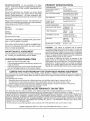
MODEL
NUMBER
SPECIFICATIONS
HORSEPOWER:
15.5
GASOLINE CAPACITY
AND TYPE:
35 GALLONS
UNLEADED REGULAR
OlL TYPE (API+SFiSG):
SAE 10W30 (above 32°F)
SAE 5W-30 (below 32°F)
OIL CAPACITY:
W/FILTER:
W/O FILTER:
SPARK PLUG:
(GAP: .040")
CHAMPION
VALVE CLEARANCE:
NOT ADJUSTABLE
GROUND SPEED (MPH):
FORWARD:
REVERSE:
TIRE PRESSURE:
FRONT:
REAR:
CHARGING
3 AMPS BATTERY
5 AMPS HEADLIGHTS
917 256591
SERIAL
NUMBER
SYSTEM:
DATE OF PURCHASE
THE MODELAND SERIAL NUMBERSWILL
ON A PLATE UNDER THE SEAT..
BE FOUND
YOU SHOULD RECORD BOTH SERIAL NUMBER AND
DATE OF PURCHASE AND KEEP tN A SAFE PLACE
FOR FUTURE REFERENCE.
CUSTOMER
+
.
-
is available on this prod+
store for details..
RESPONSIBIMTIES
Read and observe the safety rules
Follow a regular schedule in mai.ntaining, caring for and
using your tractor.
Follow the instructions
under"Customer
Responsibilities" and "Storage" sections of this owner's manual.
LiMiTED TWO YEAR WARRANTY
RC12YC
55
2,4
t4 PSi
t0,PS!
BATTERY:
AMP/HR:
MIN CCA:
CASE SIZE:
BLADE BOLT TORQUE:
30-35 FT LBS
30
240
U1R
WARNING:
This tractor is equipped with an internal
combustion engine and should not be used on or near any
unimproved forest-covered, brush-covered or grass-covered land unless the engine's exhaust system is equipped
with' a spark arrester meeting applicable local or state laws
(if any) tf a spark arrester is used, it should be maintained
in effective working order by the operator
In the state of California the above is required by law
(Section 4442 of the California Public Resources Code),
Other states may have similar laws Federal laws apply on
federal lands A spark arrester for the muffler is available
through your nearest Sears Authorized Service Center/
Department (See REPAIR PARTS section of this manual)
IViAaNTENANCE AGREEMENT
A Sears Maintenance
Agreement
uct. Contact your nearest Sears
4 0 PINTS
3+5 PINTS
ON CRAFTSMAN
RIDING EQUBPMENT
For two (2) years from the date of purchase, if this Craftsman Riding Equipment is maintained, lubricated and tuned up according to
the instructions in the owner's manual, Sears will repair or replace, free of charge, any parts found to be defective in material or
workmanship
This Warranty does not cover:
°
Expendable items which become worn during normal use, such as btades, spark plugs, air cleaners, belts, etc
=
Tire replacement or repair caused by punctures from outside objects, such as nails, thorns, stumps, or glass
=
Repairs necessary because of operator abuse, negligence, improper storage or accident or the failure to maintain the
equipment according to the instructions contained in the owner's manual
.
Riding equipment used for commercia! or rental purposes.
LIM1TED 90 DAY WARRANTY
ON BATTERY
For ninety (90) days from date of purchase, il any battery included with this riding equipment proves defective in matedat or
workmanship and our testing determines the battery will not hold a charge, Sears will replace the battery at no charge
IN-HOME WARRANTY SERVICE ON YOUR CRAFTSMAN RIDING EQUIPMENT IS AVAILABLE AT NO-CHARGE FOR 30 DAYS
FROM THE DATE OF PURCHASE
PLEASE CONTACT YOUR NEAREST SERVICE CENTER. AFTER 30 DAYS FROM THE
DATE OF PURCHASE, WARRANTY SERVICE IS AVAILABLE BY TAKING YOUR CRAFTSMAN RIDING EQUIPMENT TO YOUR
NEAREST SEARS SERVICE CENTER
(IN-HOME WARRANTY SERVICE WILL STILL BE AVAILABLE AFTER 30 DAYS FROM
THE DATE OF PURCHASE BUT A STANDARD TRIP CHARGE WILL APPLY ) THIS WARRANTY APPLIES ONLY WHILE THiS
PRODUCT IS IN THE UNITED STATES
Tinis Warranty gives you specific legal fights, and you may also have other rights which may vary from state to state
SEARS,
ROEBUCK
AND CO,
.........
D/817 WA, HOFFMAN
iiii ...............
3
ESTATES,
fL 60179
........
]
i i in i,
•
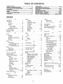
TABLE OF CONTENTS
SAFETY RULES ............................................................
2
PRODUCT SPECIFICATIONS ...................................... 3
CUSTOMER RESPONSIBILITIES ..................... 3, 16-19
WARRANTY ..................................................................
3
TABLE OF CONTENTS ................................................. 4
INDEX ............................................................................
4
TRACTOR ACCESSORIES ..........................................
5
ASSEMBLY ...............................................................
7-9
OPERATION ..........................................................
10-15
MAINTENANCE SCHEDULE .....................................
16
SERVICE AND ADJUSTMENTS ........................... 20-25
STORAGE ...................................................................
26
TROUBLESHOOTING
...........................................
27-28
REPAIR PARTS =TRACTOR ................................ 30-47
REPAIR PARTS - ENGINE ....................................
48-53
PARTS ORDERING/SERVICE .................. BACK PAGE
mNDEX
A
Accessories ..................................
5
Adjustments:
Brake ............................................. 22
Carburetor ..................................
25
Mower:
Front-To-Back
21
Side-To-Side ............................ 21
Throttl e Control Cable ....................24
Air Filter, Engine .................................... 18
Air Screen, Engine ................................ 18
Assembly ...................................................7-9
........................
B
Battery:
Charging ...................................................
8
Cleaning ......................................
t7
Starting with Weak Battery ........ 23
Storage ....................................... 26
Terminals ...................................
17
Belts:
Motion Drive
Removal!Replacement
.......... 22
Mower Blade Drive
Removal/Replacement
...............
22
Blade:
Sharpening ................................... 17
Replacement ..............................
17
Brake Adjustment
22
Engine:
Air Filter ................................
18
Air Screen .................................
18
Cooling Fins, Engine ...................... 19
Oil Change ......................................18
Oil Level ................................... 13,18
Oil Type ........................................ 18
Preparation .................................... 13
Repair Parts ........................... 48-53
Starting .....................................
14
Storage ...................................
26
F
Filters:
Air .................................................
18
Fuel ....................................
19
Fuel:
Type ....................................
13
Storage ......................................... 26
Fuse ........................................... ......... 24
G
Gauge Wheels ..............................
H
Hood Removal/Installation ..............
Carburetor Adjustment ....................... 25
Controls, Tractor ................................. t 1
Customer Responsibilities .............. 16-19
Engine:
Air Filter ...........................................
18
Air Screen, Engine .......................18
Battery ..............................................
17
Coofing Fins, Engine ................ 19
Engine Oil .................................. 18
Fuel Fitter ................................. 19
Spark Plugs ................................ 19
Tractor:
Blades ........................................ 17
Lubrication Chart ....................... 16
Maintenance Schedule ............. 16
Tire Care ........................... 9,17,23
Cutting Height, Mower ..............................
12
E
Electrical:
Interlocks and Relays ................... 24
Schematic ......:......................................
29
Wiring Diagram ........................... 30
24
L
Leveling Mower Deck .................
Lubrication Chart ...........................
21
16
M
..................................
C
9
Maintenance Schedule ....................
16
Mower:
Adjustment, Front-to-Back ........... 21
Adjustment, Side-to-Side ......... 21
Blade Sharpening
Blade Replacement ........................ 17
Cutting Height ................................ 12
installation ..................................
20
Operation ......................................... 13
Removal .....................................
20
Mowing Tips ............................................. 14
Muffler ...............................................
19
Spark Attester ..................................
3,40
Mulcher Plate ......................................... 9
.............................
1
7
O
Oil:
Cold Weather Conditions ........ 13, t8
Engine
Storage ............................................ 26
Operation ...........................................10-15
Operating Mower ................................. I3
...............................................
1
4
8
Options:
Accessories ..........................
,5
Spark Attester .............................. 3,40
P
Parking Brake ..........................
11-t2
Parts Bag ............................................. , 6
Parts, Replacement/Repair
..............30-47
Product Specifications
3
R
...................................
Repair Parts ..................................... 30-47
S
Safety Rules .......................................
2
Seat ......................................................
8
Service and Adjustments ............... 20*25
Brake ..........................................
22
Carburetor ...................................
25
Fuse ...................................
24
Hood Removal/Installation
......... 24
Motion Drive Belt
Removal/Replacement
........ 22
Mower Blade Drive Belt
Removal/Replacement
........... 22
Mower Adjustment:
Front-to-Back ...................
21
Side-to-Side ......................... 21
Mower lnstatiation .....................
20
Mower Removal .......................... 20
Tire Care
g,17,23
Slope Guide Sheet .............................. 55
Spark Plugs
19
Specifications .......................................
3
Starting the Engine ........................ 13-14
Steering Wheel ................................
7,23
Stopping the Tractor
12
Storage ................................................... 26
T
...............................
..........................................
...............................
Throttle Control Cable Adjustment .... 24
Tires ..........................................
9,17,23
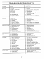
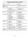
Trouble Shooting Chart .......................
27-28
Transaxle Repair Parts .................
W
46-47
Warranty .................................................
3
Wiring Diagram ..................................
30
Wiring Schematic ............................... 29
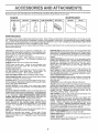
ACCESSORUE$
i
,i i,i1,1, H,
i,
,,
AN
i i,,,111....
ATTACHMENTS
,...........................
,
, ,i,ii,,
i ,,
ii U,ill
These accessories and attachments were avaifab{e through most Sears retail outlets and service centers when the tractor was purchased.
Most Sears stores can order these items for you when you provide the model number of your tractor
ENGINE
SPARK PLUG
MAINTENANCE
GAS CAN
ENGINE OIL
FUEL STABILIZER
AIR FILTER
BLADES
BELTS
%
G
PERFORMANCE
Sears offers a wide variety of attachments that fit your tractor.
you This list was current at the time of publication; however,
may be made in these attachments, or some may no longer
accessories and attachments
that are available for your
Most of those attachments do not require additional hitches
attaching and detaching
Many of these are {isted below with brief explanations of how they can help
it may change in future years - more attachments may be added, changes
be available or fit your model Contact your nearest Sears store for the
tractor..
or conversion kits (those that do are indicated) and are designed for easy
SNOW BLADE for snow removal only. 14-inch high, 48-inch wide
blade clears 42-inch path when angled left or right Raises, lowers
with side Lever. Adjustable skids; replaceable, reversible scraper
bar. (Use with tire chains and wheel weights and/or rear drawbar
weight.)
SNOWTHROWER has 40-inch swath Drum-type auger handles
powdery and wet/heavy snow
Mounts easily with simple pin
arrangement.. Discharge chute adjusts from tractor seat 6-inch
diameter spout discharges snow !0 to 50 feet Lift controlled at
tractor seat. (Use with chains and wheel weights and/or rear
drawbar weight )
SPRAYERS use 12-volt DC e_ectric motor that connects to the
tractor battery or other 12-volt source
Inctudes booms for
automatic spraying and hand held wand for spot spraying. Wand
has adjustable spray pattern
For applying herbicides, insecticides, fungicides and liquid fertilizers.
AERATOR promotes deep root growth for a healthy lawn. Tapered 2 5-inch steel spikes mounted on 10-inch diameter discs
puncture holes in soil at close intervals to let moisture soak in.
Steel weight tray for increased penetration
BAGGER lets you collect
grass clippings and leaves for a
healthier, nearer look ng lawn Two Permanex containers hold
30-gallon plastic bags
BUMPER protects front end of tractor from damage.
CARTS make hauling easy
Variety of sizes available, plus
accessories suct_ as side panel kits, too! caddy, cart cover,
protective mat and dolly,
CORING AERATOR takes small plugs out of soil to allow moisture and nutrients to reach grass roots
36-inch swath
24
hardened steel coring tips° I50 Ib. capacity weight tray
EASY OIL DRAIN VALVE makes oi! changes easier, faster
FRONT NOSE ROLLER canters in front of mower deck to reduce
chances of "scalping" on uneven terrain
GANG HITCH lets you tow 2 or3 pull-behind attachments at once,
such as sweepers, dethatchers, aerators (not for use with rollers,
carts or other heavy attachments).
GAUGE WHEELS on both sides of the mower deck reduce
chances of"scalping" on uneven terrain For mower decks not so
equipped
MULCH RAKFJDETHATCHER
loosens soil and flips thatch and
matted leaves to Iawn surface for easy pickup Twenty spring tine
teeth. Useful to prepare bare areas for seeding. Available for front
or rear mounting,
HIGH PERFORMANCE
REEL-ACTION
SPRING TINE DETHATCHER covers 36-inch wide path and
tosses thatch into large hopper Mounts behind tractor
MULCHING CLOSE-OUT PLATE KIT, once installed, lets you
mulch, d_scharge or bag clippings (bagger optional) without
changing blades For models not equipped as 3-in-1 Convertible
mowers.
See "MOWER" in the Repair Parts section of this
manual
SPREADERISEEDERS
make seeding, fertilizing, and weed killing easy. Broadcast spreaders are also useful for granular deicers and sand
SWEEPERS let you collect grass clippings and leaves
TILLER has 5 hp engine and 36-inch swath to prepare seed beds,
cultivate and compost garden residue. Tiller has its own built-in
lift and depth control system and does NOT require a sleeve hitch
Fits any fawn, yard or garden tractor Simply hook up to the tractor
drawbar and go!
Optional
accessories
convert unit for
dethatchlng, aerating, hilling..without
tools
TIRE CHAINS are heavy duty; closely spaced extra-large cross
links give smooth fide, outstanding traction
TRACTOR CAB has heavy duty vinyl fabric over tubular steel
frame, ABS plastic top; clear plastic windshield offers 360 degree
visibility.. Hinged metal doors with catch. Keeps operator warm
and dry Remove vinyl sides and windshields for use as sun
protector in summer
Optional accessories
include:
tinted/
tempered solid safety glass windshield with hand opei'ated wiper;
12-volt amber caution light for mounting on cab top.
VACS for powerful collection of heavy grass clippings and leaves
Optional wand attachment
to pick up debris in hard-to-reach
places VAClCHIPPER includes a chipper--shredder
WEIGHT BRACKET for drawbar for snow removal applications.
Uses (1) 55 Ib. weight
WHEEL WEIGHTS for rear wheels provide needed traction for
snow removal or dozing heavy materials
RAMP TOPS AND FEET let you load and unload tractor from a
pickup truck
Use with 2 x 8 or 2 x 10 fumber
ROLLER for smoother lawn surface.
36-inch wide, 18-inch
diameterwater-tight drum holds up to 390 tbs of weight Rounded
edges prevent harm to turf Adjustable scraper automatically
cleans drc_m
5
m
CONTENTS
.....
,u,,,
i
OF HARDWARE
PACK
i.....................
a
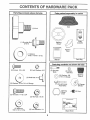
Parts B g contents
....................
in ..................
shown
full size
Parts
........
,,
uu lU , u
packed
separately
-
lu .....
.....
in carton
ii ,,
Seat
(1) Knob
(1) Shoulder Bolt
5/16-18
Video
Cassette
Steering
Wheel
Plate
(1) Washer
17/32 x 1-3/t6 x t2 Ga.
'
Mulcher
I
Manual
,,
....... ii ....
unlu
Parts Bag
,,,,ll,,,u
,,,
,
,i,,i,,
(2) Lock Washers
,,i
Parts bag contents
@
(2) Screws #10 x 5/8
Ul, i i,
,
,,i
, ,,11
.......
not shown full size
©
#t0
(2) Shoulder
Bolts
(2) Centerlock Nuts
(2) Washers 3/8
x 7/8 x 14 Gauge
Steering
Sleeve
(2) Weld Nuts #10
(2) Washers
3/I6 x 3/4 x 16 Gauge
Assemblies
(2) Hex Bolts 1/4-20 x 3/4
@
Steering
Wheel
Insert
(2) Hex Nuts 1/4-20
(2) Washers
9/32 x5/8xt6Ga
(2) Lock Washers
1/4
Slope Sheet
6
(2) Keys
ASSEMBLY
.....................
=,
...................
I,II
n,,lll,
Ill
II I lu,I
Your new tractor has been assembled at the factory with exception of those parts left unassembled for shipping purposes.
To ensure safe and proper operation of your tractor ai] parts and hardware you assemble must be tightened securely_ Use
the correct tools as necessary to insure proper tightness.
TOOLS REQUIRED
FOR ASSEMBLY
A socket wrench set will make assembly easier, Standard
wrench sizes are listed,
(1) 5/16" wrench
(1) 3/4" Socket w/drive rachet
(2) 7/!6" wrenches
Phillips Screwdriver
(1) 1/2" wrench
Tire pressure gauge
(1) 9/16" wrench
Utility knife
When right or left hand is mentioned in this manua}, it
means when you are in the operating position (seated
behind the steering wheel)
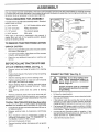
TO REMOVE TRACTOR
UNPACK
o
FROM CARTON
STEERING
CARTON
"----_-,-..,,,_A:i!_,.:,
Remove all accessible loose parts and parts cartons
from carton (See page 6),
•
Cut, from top to bottom, along lines on all four corners
of carton, and tay panels flat
.
Check for any additional
remove.
t /
.:'_'1'_
loose parts or cartons and
I
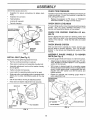
ATTACH
STEERING
WHEEL
Remove Iocknut and large flat washer from steering
shall
°
Position front wheels of the tractor so they are pointing
straight forward.
.
Slide the steering sleeve over the steering shaft,,
.
Position steering wheel so cross bars are horizontal
(left to right) and slide onto adapter.
o
Secure steering wheel to steering shaft with locknut
and large flat washer previously removed. Tighten
securely
CONNECT
"7
.
Release parking brake by depressing clutch/brake
peda!.
Place freewheel control in freewheeling position to
disengage transmission (See "TO TRANSPORT" in
the Operation section of this manual),
Roll tractor backwards off skid.
°
-
_'"
/
/
l/
,
/
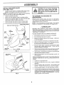
BATTERY
(See Fig. 2)
Positive terminal must be connected
first to prevent sparking from accidental grounding.
Lift hood to raised position,.
Open terminal access doors, remove terminal protective caps and discard.
If this battery is put into service after month and year
indicated on label (label located between terminals)
charge battery for minimum of one hour at 6-I0 amps
OFF SKID (See Operation
and function
of controls)
Press lift lever plunger and raise attachment lift lever to
its highest position.
.°
CAUTION: Do not short battery terminals. Before connecting battery, remove metal bracelets,
wristwatch
bands, rings, etc.
.
Remove protective plastic from tractor hood and grill,
IMPORTANT: CHECK FOR AND REMOVE ANY STAPLES
tN SKID THAT MAY PUNCTURE TIRES WHERE TRACTOR
IS TO ROLL OFF SKtD
,
SLEEVE
FiG. 1
Snap steering wheel insert into center of steering
wheel,
TO ROLLTRACTOR
section for location
I
(See Fig. 1)
=
•
t
/
/_--._
t
BEFORE ROLLING TRACTOR OFF SKiD
.,STEER,NG
;_IF_
First connect RED battery cable to positive (+) battery
terminal with hex bolt, flat washer, lock washer and hex
nut as shown Tighten securely.
Connect BLACK grounding cable to negative (-) battery terminal with remaining hex bolt, flat washer, lock
washer and hex nut. Tighten securely.
Close terminal access doors°
Remove banding holding discharge guard up against
tractor
7
LY
mll_ll,!,l,,
1,1,11¸11111111
ii
H
I I
Use terminal access doors for:
CHECK
(to tighten hard-
TIRE PRESSURE
.
Inspection for secure connections
ware).
o
Inspection for corrosion
The tires on your tractor were overinflated at the factory for
shipping purposes Correct tire pressure is important for
best cutting performance.
o
Testing battery,
-
o
Jumping (if required).
°
Periodic charging.
Reduce tire pressure to PSI shown in "PRODUCT
SPECIFICATIONS" on page 3 of this manual
CHECK
LOCK
WASHER
HEX NUT
For best cutting results, mower housing should be properly
leveled_ See "TO LEVEL MOWER HOUSING" in the
Service and Adjustments section of this manual.
FLAT
WASHER
DISCARD TERMINAL
PROTECTIVE CAPS
HEX
BOLT
CHECK
TERMINAL ....
ACCESS
DOOR
POSITIVE
(RED).
CABLE _
CHECK
Place seat on seat pan and assemble shoulder bolt.
,
Assemble adjustment knob and flat washer loosely.
Do not tighten.
•
Tighten shoulder bolt securely..
,
Lower seat into operating position and sit on seal
,
Slide seat until a comfortable position is reached which
allows you to press clutch/brake pedal all the way
down.
°
Get off seat without moving its adjusted position.
o
Raise seat and tighten adjustment knob securely.
SEAT PAN
POSITION
OF
ALL
SYSTEM
WHEELS
TO
MOWER
Assemble gauge wheels with tractor on a flat level surface.
Adjust seat before tightening adjustment knob.
=
BRAKE
ASSEMBLE
GAUGE
DECK (See Fig. 4)
SEAT (See Fig. 3)
Remove cardboard packing on seat pan.
PROPER
After you learn how to operate your tractor, check to see
that the brake is propedy adjusted. See 'q'O ADJUST
BRAKE" in the Service and Adjustments section of this
manual.
FIG. 2
=
FOR
See the figures that are shown for replacing motion and
mower blade drive belts in the Service and Adjustments
section of this manual
Verify that the belts are routed
correctly
_'
NEGATIVE
(BLACK)
CABLE
INSTALL
DECK LEVELNESS
,
Adjust mower' to desired cutting height (See "TO ADJUST MOWER CUTTING HEIGHT"in the Operation
section of this manual)°
o
With mower in desired height of cut position, gauge
wheels should be assembled so they are slightly off the
ground. Install gauge wheel in appropriate hole with
shoulder bolt, 3/8" washer and 3/8-16 Iocknut and
tighten securely.
,
Repeat for opposite side installing gauge wheel in
same adjustment hole.
GAUGE WHEEL
MOUNTING
]
SEAT
SHOULDER
BOLT
318-16
LOCKNUT
\.\:
318" WASHER
GAUGE WHEEL
'FLATWASHER
ADJUSTMENT
KNOB
SHOULDER
"_
FIG. 4
FIG. 3
8
...._
BOLT
mN,,l=, ,,-r,
ASSEMBLY
i
.=
INSTALL MULCHER
(See Figs. 5 & 6)
PLATE
Install two latch hooks to mulcher plate using screw,
washer, lock washer, and weld nut as shown
NOTE: Pre-assemble weld nut to latch hook by inserting
weld nut from the top with hook pointing down°
o
Tighten hardware securely.
o
Raise and hold deflector shield in upright position.
Place front of mufcher plate over front of mower deck
opening and slide into place, as shown.
°
Hook front latch into hole on front of mower deck.
o Hook rear latch into hole on back of mower deck.
CAUTION: Do not remove discharge
guard from mower. Raise and hold
guard when attaching mulcher plate
and allow it to rest on plate while in
operation.
TO CONVERT
DISCHARGING
TO BAGGING
]
|
i
|
|
OR
Simply remove mulcher plate and store in a safe place.
Your mower is now ready for discharging or installation of
optional grass catcher accessory
NOTE: tt is not necessary to change blades.. The mulcher
blades are designed for discharging and bagging also_
HOOK POINTS DOWN
WELD NUT FROM THE TOP
,/'CHECKLIST
BEFORE YOU OPERATE AND ENJOY YOUR NEW
TRACTOR, WE WISH TO ASSURE THAT YOU RECEIVE
THE BESTPERFORMANCE AND SA TISFA CTION FROM
THIS QUALITY PRODUCT
LOCK
WELD
WASHER
PLEASE REVIEW THE FOLLOWING
NUT_
CHECKLIST:
SCREW
LATCH
,/
All assembly instructions have been completed..
v"
No remaining loose parts in carton
v"
Battery is properly prepared and charged..
1 hour at 6 amps)..
v"
Seat is adjusted comfortably and tightened securely.
7"
All tires are properly inflated. (For shipping purposes,
the tires were overinflated at the factory)
¢'
Be sure mower deck is properly leveled side-to-side/
front-to-rear for best cutting results. (Tires must be
properly inflated for leveling).
Check mower and drive belts. Be sure they are routed
properly around pulleys and inside all belt keepers,
Check wiring, See that all connections are still secure
and wires are properly clamped
HOOK
LOCK
WASHER
WASHER
WELD
NUT
WASHER
MULCHER
PLATE
d"
FIG_ 5
¢'
,/
DEFLECTOR
SHIELD
(Minimum
Before driving tractor, be sure freewheel control is in
drive position°
WHILE LEARNING HOW TO USE YOUR TRACTOR, PAY
EXTRA A TTENTION TO THE FOLL 0 WING IMPOR TANT
ITEMS:
¢'
,z
v'
LATCH
HOOKS
FIG. 6
9
Engine oil is at proper level,.
Fuel tank is filled with fresh, clean, regular unleaded
gasoline.
Become familiar with all controls - their location and
function. Operate them before you start the engine
,/
Be sure brake system is in safe operating condition.
¢
It is important to purge the transmission before operating your tractor for the first time. Foltow proper starting
.....
and transmission
purging mstructlons (See "TO STAR T
ENGINE and PURGE TRANSMISSION
in the Operation section of this manual).
'
.i.........................................
i
OPERATION
m
i
mu,Hn
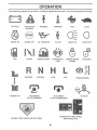
These symbols may appear on your tractor or in literature supplied with the product. Learn and understand their meaning.
÷
BATTERY
CAUTION OR
WARNING
REVERSE
FORWARD
FAST
SLOW
ENGINE ON
ENGINE OFF
OIL PRESSURE
CLUTCH
LtGHTS ON
LIGHTS OFF
FUEL
CHOKE
MOWER HEIGHT
DIFFERENTIAL
LOCK
PARKING BRAKE
LOCKED
UNLOCKED
REVERSE
NEUTRAL
HIGH
L
oSl
LOW
PARKING BRAKE
÷
MOWER LIFT
ATTACHMENT
CLUTCH ENGAGED
ATTACHMENT
CLUTCH DISENGAGED
HYDROSTATIC
DANGER, KEEP HANDS AND FEET AWAY
IGNITION
FREE WHEEL
(Hydro Models only)
10
i
OPERATION
, ,i,
, ii .........................
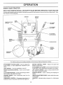
KNOW YOUR TRACTOR
READ THIS OWNER'S
MANUAL
AND SAFETY
RULES
BEFORE
OPERATING
YOUR
TRACTOR
Compare the illustrations with your tractor to familiarize yourself with the locations of various controls and adiustments
this manual for future reference°
AMMETER
IGNITION
SWITCH
LIGHT
SWITCH
THROTTL_CHOKE
CONTROL
LIFT LEVER
PLUNGER
ATTACHMENT
LIFT LEVER
CLUTCH/
PEDAL
BRAKE
Save
_
ATTACHMENT
CLUTCH LEVER
HEIGHT
ADJUSTMENT
KNOB
PARKING
BRAKE
MOTION
CONTROL
LEVER
APPROX_
SPEED
3 MPH
FF
CONTROL
,:"
1MPH
FIG, 7
Our tractors conform to the safety standards of the American National Standards Institute.
MOTION CONTROL LEVER
direction of the tractor_
ATTACHMENT CLUTCH LEVER: Used to engage the
mower biades, or other attachments mounted to your
tractor.
LIGHT SWITCH:
CONTROL:
the speed and
ATTACHMENT LIFT LEVER: Used to raise and lower the
mower deck or other attachments mounted to your tractor.
LIFT LEVER PLUNGER: Used to release attachment iift
lever when changing its position_
Turns the headlights on and off.
THROTTLE/CHOKE
speed.
- Selects
Used to control engine
CLUTCH/BRAKE PEDAL: Used for declutching and braking the tractor and starting the engine,
IGNITION SWITCH:
engine,
PARKING BRAKE: Locks clutch/brake pedal into the
brake position.
FREEWHEEL CONTROL - Disengages transmission for
pushing or slowly towing the tractor with the engine off
HEIGHT ADJUSTMENT
cutting heighL
AMMETER:
(-)
11
Used for starting and stopping the
KNOB: Used to adjust the mower
indicates battery charging (+) or discharging
,HHmp,,= H,,,
=,,,,==, ==, === , ,,
OPERATgON
u:J_,J=
_
_
s_ _
L
=,m,
, = 11
= 1,
The operation of any tractor can result in foreign objects thrown into the eyes, which can
result in severe eye damage. Always wear safety glasses or eye shields while operating your
over the spectacles
or Standard safety glasses=
tractororperforminganyadjustmentsorrepairs.
_'_
_
,,,_ =,,=,,,=H==
m,,H=,
N,H,,
PARKING
BRAKE
....................
NOTE: Under certain conditions when tractor' is standing
idle with the engine running, hot engine exhaust gases may
cause "browning" of grass, To eliminate this possibility,
always stop engine when stopping tractor on grass areas.
(See Fig. 8)
Your tractor is equipped with an operator presence sensing
switch, When engine is running, any attempt by the
operator to leave the seat without first setting the parking
brake will shut off the engine,_
Depress clutch/brake
and hold.
o
,,,,
Place parking brake lever in "ENGAGED" position and
release pressure frornclutch/brake pedal. Pedal should
remain in "BRAKE" position_ Make sure parking brake
wilt hold tractor secure_
THROTTLE/CHOKE
CONTROL
TO USE THROTTLE
Operating engine at less than full throttle reduces the
battery charging rate..
.
Full throttle offers the best bagging and mower performance.
TO MOVE FORWARD
(See Fig. 8)
o
Start tractor with moti()n control lever in neutral (N)
position
.
Release parking brake and clutch/brake pedal.
•
Slowly move motion control level to desired position..
TO ADJUST MOWER
(See Fig. 8)
HEIGHT ADJUSTMENT
KNOB
CUTTING
HEIGHT
The cutting height is controlled by turning the height adjust_
ment knob in desired direction,
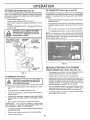
FIG. 8
(See Fig, 8)
-
Turn knob clockwise (f"-_)
•
Turn knob counterclockwise
height
MOWER BLADES =
Move attachment clutch Iever to "DISENGAGED"
sition.
AND BACKWARD
The direction and speed of movement is controlled by the
motion control lever..
"DISENGAGED"
POSITION
to raise cutting height.
(_'",,)to
tower cutting
The cutting height range is approximately 1-I/2" to 4"° The
heights are measured from the ground to the blade tip with
the engine not running. These heights are approximate
and may vary depending upon soil conditions, height of
grass and types of grass being mowed.
po-
GROUND DRIVE =
(See Fig. 8)
=
LEVER
MOTION
CONTROL
LEVER
=
CONTROL
"DISENGAGED"
"BRAKE"
POSITION
STOPPING
H,
Always operate engine at full throttle
PARKING BRAKE
"ENGAGED"
POSITION
CLUTCHIBRAKE
PEDAL "DRIVE"
POSITION
, m
CAUTION:
Always stop tractor comPnletely, as described above, before leaw
g the operator's position; to empty
grass catcher, etc.
pedal into full "BRAKE" position
ATTACHMENT CLUTCH
"ENGAGED"
POSITION
Werecommendawidevisionsafetymask
'H
HOW TO USE YOUR TRACTOR
TO SET
11,111,
Depress clutch!brake pedal into futl "BRAKE" position.
,, Move motion control lever to neutral (N) position.
IMPORTANT:
THE MOTION CONTROL LEVER DOES
NOT RETURN TO NEUTRAL (N) POSITION WHEN THE
CLUTCH/BRAKE PEDAL tS DEPRESSED
,
The average lawn should be cut to approximately 2-1/2
inches during the cool season and to over3 inches
during hot months. For healthier and better looking
lawns, mow often and after moderate growth
ENGINE -
o
For best cutting performance, grass over 6 inches in
height should be mowed twice.. Make the first cut
relatively high; the second to desired height.
o
Move throttle control to slow (,_,)
position°
NOTE: Failure to move throttle control to slow (,,{_)
position and allowing engine to idle before stopping may
cause engine to "backfire"_
o
Turn,ignition key to "OFF" position and remove key.
Always remove key when leaving tractor' to prevent
unauthorized use.
_,
Never use choke to stop engine°
12
OPERATION
TO OPERATE
MOWER
TO TRANSPORT
(See Fig. 9)
Your tractor is equipped with an operator presence sensing
switch, Any attempt by the operator to leave the seat with
the engine running and the attachment clutch engaged will
shut off the engine.
o Select desired height of cut.,
Lower mower with attachment lift control
o
Start mower blades by engaging attachment clutch
control
•
TO STOP MOWER BLADES - disengage attachment
clutch control
...........................
_
_ _
II _
,
i n,,,llnll u,
•
Raise attachment lift to highest position with attachment lift control
o
Pull freewheel control knob out and hold in position by
inserting retainer spring into forward hole of controt
rod.
o
Do not push or tow tractor at more than two (2) MPH.
o
To reengage transmission,
reverse above procedure
NOTE: To protect hood from damage when transporting
your tractor on a truck or a trailer, be sure hood is closed
and secured to tractor. Use an appropriate means of tying
hood to tractor (rope, cord, etc )_
charge guard in place"
,, ,,,,,,,
10)
When pushing or towing your tractor, be sure to disengage
transmission by placing freewheel control in freewheeling
position,, Free wheef control is located at the rear drawbar
of tractor,,
CAUTION: Do not operate the mower
without either the entire grass catcher,
on mowers so equipped, or the dis,, ,,,
(See Figs. 8 and
= = ,, NuJ,
ATTACHMENT CLUTCH
LEVER "DISENGAGED"
POSITION
FIG, 10
BEFORE STARTING
DISCHARGE
GUARD
CHECK
FIG. 9
TO OPERATE
ON HILLS
with slopes greater than 15 ° and do not
CAUTION:
not slope.
drive up or down hills
drive acrossDoany
o
Avoid stopping or changing speed on hills,
o
If slowing is necessary,
sfower position,
,
if stopping is absolutely necessary, push clutchfbrake
pedal quickly to brake position and engage parking
brake
move throttle control lever to
o Move motion control lever to neutral (N) position.
IMPORTANT:
THE MOTION CONTROL LEVER DOES
NOT RETURN TO NEUTRAL (N) POSITION WHEN THE
CLUTCH/BRAKE PEDAL IS DEPRESSED,
,
To restart movement, slowly release parking brake and
clutch/brake pedal,,
•
Slowly move motion control lever to slowest setting,
o
Make all turns slowly
13
OIL LEVEL
(See Fig. 15)
•
The engine in your tractor has been shipped, from the
factory, already filled with summer weight oil
°
Check engine oif with tractor on level ground.
=
Unthread and remove oil fitl cap/dipstick; wipe oil off.
Reinsert the dipstick into the tube and rest oil fill cap on
the tube. Do not thread the cap onto the tube. Remove
and read oil level, If necessary, add oil until "FULL"
mark on dipstick is reached Do not overfill.
.
For cold weather operation you should change oil for
easier starting (See "OIL VISCOSITY CHART" in the
Customer Responsibilities section of this manual),.
°
To change engine oil, see the Customer Responsibilities section in this manual
I
Choose the slowest speed before starting up or down
hills,
ENGINE
THE ENGBNE
OPERATION
....................
l!,ll
ii
,
i
ADD GASOLINE
o
o
o
Fill fuel tank.. Use fresh, clean, regular unleaded
gasoline with a minimum of 87 octane. (Use of leaded
gasoline will increase carbon and lead oxide deposits
and reduce valve life).. Do not mix oil with gasoline.
Purchase fuel in quantities that can be used within 30
days to assure fuel freshness.
IMPORTANT: WHEN OPERATING iN TEMPERATURES
BELOW 32°F(0°C), USE FRESH, CLEAN WINTER GRADE
GASOLINE TO HELP fNSURE GOOD COLD WEATHER
STARTING,
WARNING:
Experience indicates that alcohol blended
fuels (called gasohol or using ethanol or methanol) can
attract moisture which leads to separation and formation of
acids dudng storage, Acidic gas can damage the fuel
system of an engine while in storage To avoid engine
problems, the fuel system should be emptied before storage of 30 days or longer. Drain the gas tank, start the
engine and let it run until the fuel lines and carburetor' are
empty. Use fresh fuel next season. See Storage Instructions for additional information.
Never' use engine or
carburetor cleaner products in the fuel tank or permanent
damage may occur.
_ _
!
'TO START
o
o
PURGE
TRANSMISSION
CAUTION: Never engage or disengage
freewheel lever while the engine is running,
(See Fig. 9)
When starting the engine for the first time or if the engine
has run out of fuel, it will take extra cranking time to move
fuel from the tank to the engine_
To ensure proper operation and performance, it is recommended that the transmission be purged before operating
tractor' for the first time° This procedure will remove any
trapped air inside the transmission which may have developed during shipping of your tractor
IMPORTANT: SHOULD YOUR TRANSMISSION REQUIRE
REMOVAL FOR SERVICE OR REPLACEMENT,
IT
SHOULD BE PURGED AFTER REINSTALLAT1ON
BEFORE OPERATING THE TRACTOR
°
o
Depress crutch/brake pedal and set parking brake.
Pface motion control lever in neutral (N) position..
o Move attachment clutch to "DISENGAGED" position.
o Move throttle control to choke (l\l) position,
Note: Before starting, read the warm and cold starting
procedures below.
o
o
•
.
_nsertkey into ignitionand turn key clockwise to"START"
position and release key as soon as engine starts. Do
not run starter continuously for more than fifteen seconds per minute
If the engine does not start after
several attempts, move throttle control to fast (,_)
position, wait a few minutes and try again, if engine stilt
does not start, move the throttle control back to the
choke (N) position and retry.
Place tractor safely on level surface with engine off and
parking brake set,
Disengage transmission by placing freewheel control
in freewheeling position (See "TO TRANSPORT" in
this section of manual),
Sitting in the tractor seat, start engine, After the engine
is running, move throttle control to slow (-_) position,.
With motion control lever in neutral (N) position, slowly
disengage clutch/brake pedal
Move motion control lever to full forward position and
hold for' five (5) second& Move lever to full reverse
position and hold for five (5) seconds.. Repeat this
procedure three (3) times,,
NOTE: During this procedure there will be no movement of
drive wheel& The air is being removed from hydraulic drive
system_
°
Move motion control lever' to neutral (N) position_ Shutoff engine and set parking brake
WARM WEATHER STARTING (50 ° F and above)
o When engine starts, move the throttle control to the fast
(,@) position..
The attachments and ground drive can now be use& If
the engine does not accept the load, restart the engine
and allow it to warm up for one minute using the choke
as described above.
=
o
COLD WEATHER STARTING ( 50 ° F and below)
o When engine starts, atlow engineto run with thethrottle
control in the choke (I\) position until the engine runs
roughly, then move thrott e contro to fast (=_) position.
This may require an engine warm-up period from
several seconds to several minutes, depending on the
temperature.
HYDROSTATIC TRANSMISSION WARM UP
Before driving the unit in cold weather, the transmission should be warmed up as follows:
The attachments can also be used during the engine
warm-up period after the transmission has been warmed
up.
NOTE: If at a high altitude (above 3000 feet) or in cold
temperatures (below 32 F) the carburetor fuet mixture may
need to be adjusted for best engine perfor mance. See "TO
ADJUST CARBURETOR" in the Service and Adjustments
section of this manual
gas tank ............
j
fillerneek.
Do not overfiU. Wipeoffany
spilled oil or' fuelo Do not store, spill or
J
use gasoline near an open flame,
j
ENGINE
Be sure the tractor' is on level ground.
Place the motion control lever in neutral
Release the parking brake and let the clutch/brake
slowly return to operating position..
Allow one minute for' transmission to warm up.
This can be done during the engine warm up
period.
o
•
14
Engage transmission by placing freew!leel control in
driving position (S..e TO TRANSPORT Jnth,s section
of manual).
Sitting in the tractor seat, start engine° After the engine
is running, move throttle control to half (1/2) speed.
With motion control lever in neutral (N) position, slowly
disengage clutch/brake pedal
Slowly move motion control lever' forward, after the
tractor moves approximately five (5) feet, slowly move
motion control lever to reverse position.. After the
tractor moves approximately five (5) feet return the
motion control lever to the neutral (N) position. Repeat
this procedure with the motion control lever three (3)
times°
Your tractor is now purged and now ready for normal
operation
OPERATION
m_
MOWING
MULCHING
TIPS
o
Tire chains cannot be used when the mower housing is
attached to tractor°
o
Mower should be properly leveled for best mowing
performance. See "TO LEVEL MOWER HOUSING" in
the Service and Adjustments section of this manual.,
.
The left hand side of mower should be used for trimruing.
Drive so that clippings are discharged onto the area
that has been cut. Have the cut area to the right of the
machine. This wiil result in a more even distributio n of
clippings and more uniform cutting.
°
•
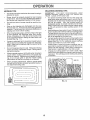
When mewing large areas, start by turning to the right
so that clippings will discharge away from shrubs,
fences, driveways, etc. After one ortwo rounds, mow
in the opposite direction making left hand turns until
finished (See Fig. 11 ).
.
If grass is extremely tall, it should be mowed twice to
reduce load and possible fire hazard from dried clippings.. Make first cut relatively high; the second to the
desired height
•
Do not mow grass when it is wet Wet grass will plug
mower and leave undesirable clumps.. Allow grass to
dry before mowing..
.
Always operate engine at full throttle when mowing to
assure better mowing performance and proper discharge of material Regulate ground speed by selecting a low enough gear to give the mower cutting
performance as well as the quality of cut desired.
o
When operating attachments, select a ground speed
that will suit the terrain and give best performance of
the attachment being used
MOWING
...............................
TIPS
IMPORTANT:
FOR BEST PERFORMANCE,
KEEP
MOWER HOUSING FREE OF BUILT-UP GRASS AND
TRASH, CLEAN AFTER EACH USE
o The special mulching btade will recut the grass clippings many times and reduce them in size so that as
they fall onto the lawn they will disperse into the grass
and not be noticed, Also, the mutched grass will
biodegrade quickly to provide nutrients for the Iawn.
Always mulch with your highest engine (blade) speed
as this wilt provide the best recutting action of the
blades
o Avoid cutting your lawn when it is weL Wet grass tends
to form clumps and interferes with the mulching action.
The best time to mow your lawn is the early afternoon_
At this time the grass has dried and the newly cut area
will not be exposed to the direct sun,
*
For best results, adjust the mower cutting height so that
the mower cuts off only the top one-third of the grass
blades (See Fig. 12),, For extremely heavy mulching,
reduce your width of cut and mow slowly,
o Certain types of grass apd grass conditions may require that an area be mulched a second time to completely hide the clippings° When doing a second cut,
mow across or perpendicular to the first cut path
o Change your cutting pattern from week to week° Mow
north to south one week then change to east to west the
next week This will help prevent matting and graining
of the lawn.
r,
f
1
FIG_ t 2
,,,,,,,,,,,,,
FIG. 11
15
1
MAX ti3
CUSTOMER
,,
ESPONSHBILBTJlES
__
--
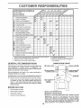
FILL iN DATES
,
' ._._,-O_'_.,
AS YOU COMPLETE
L_
REGOLAR
SERV,CE
.......
Check Brake 0potation
____
.I '%RVlOE
DATES
'" I"_ ................. _'"
Check Tire Pressure
_
T
Check for Loose Fasteners
,_
Sharpen/Replace
C
Lubdcalion
T
Check Battery Level!Recharge
0
Clean Battery
a
Check Transaxle
6##
Mower Blades
Chart
and Terminals
Cooling
Adjust
Blade Belt(s) Tension
Adjust
Motion Drive Belt(s) Tension
Check
Engine
Change
,
e,'
e,'
e,'
Oil Level
Engine Oit
Clean Air Filter
E
N
Clean Air Screen
G
inspect Muffler/Spark
Replace
N
v'
Arrestor
Oi1 Filter (If equipped)
Clean Engin'e Cooling
IE
e"_i
Fir,s
Replace
Spark Plug
Replace
Air Filter Paper Cartridge
Replace
Fuel Filter
v'
t - Change more often when operating under a heavy load o_'In high ambienl temperatures
2 - Service more often when operating in dirty or dusty conditions
3 * tf equipped with off fillet, change oil every 50 hours
4 - Replace biades more otten when mowing tn sandy sell
GENERAL
e,'
5 * II equipped with adjustable sysiem
6 - Not required _fequfpped with maintenance-free battery
7 - Tighlen Iront axie pivof bolt to 35 It 4ha maximum
Do no_ overltghten
RECOMMENDATIONS
LUBRICATION
The warranty on this tractor does not cover items that have
been subjected to operator abuse or negligence,
To
receive full value from the war ranty, operator must maintain
tractor as instructed in this manual
CHART
® SPtND'E
ZERK
----IF------_F---
SPINBLE
ZERK
®
_)
FRONT
FRO NT WHEEL_::::::::::::::::::::::::::_
WHEEL-_'
BEARING
Some adjustments will need to be made periodically to
properly maintain your tractor,
ZERK
_!
"_J
_
REARING
All adjustments in the Service and Adjustments section of
this manual should be checked at least once each season..
o
EACH
ZERK
ENGINE ®
Once a year you should replace the spark plug, clean
or replace air filter, and check blades and belts for
wear, A new spark plug and clean air fitter assure
proper air-fuel mixture and help your engine run better
and last longer.
BEFORE
®
®
CLUTCH
PIVOT(S)
USE
-
Check engine oil level
°
Check brake operation.
(_) SAE 30 OR lOW30 MOTOR OIL
o
o
Check tire pressure,
Check for loose fasteners.
®
GENERAL PURPOSE
®
REFER TO CUSTOMER
GREASE
RESPONSIBILITIES
"ENGINE"
SECTION
IMPORTANT:
DO NOT OIL OR GREASE
THE PIVOT POINTS
WHICH HAVE SPECIAL NYLON BEARINGS,
VISCOUS
LUBRICANTS WILL ATTRACT
DUST AND IJtRT THAT WILL SHORTEN
THE LIFE OF THE SELF-LUBRICATING
BEARINGS,
IF YOU
FEEL THEY MUST BE LUBRICATED,
USE ONLY A DRY, POWDERED GRAPHtTE
TYPE LUBRICANT
SPARINGLY
16
.....................
CUSTO
1,n
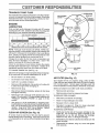
o
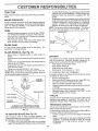
To check blade balance, you will need a 5/8" diameter
steel bolt, pin, or a cone balancer_ (When using a cone
balancer, follow the instructions supplied with balancer),
o
Slide blade onto an unthreaded portion of the steet bolt
or pin and hold the bolt or pin parallel with the ground.
if blade is balanced, it should remain in a hodzontaf
position, if either end of the blade moves downward.
sharpen the heavy end until the blade is balanced
NOTE: Do not use a nail for balancing blade, The lobes of
the center hole may appear to be centered, but are not,
TRACTOR
Always observe safety rules when performing any maintenance.
OPERATION
If tractor requires more than six (6) feet stopping distance
at high speed in highest gear, then brake must be adjusted
(See "TO ADJUST BRAKE" in the Service and Adjustments section of this manual)
TIRES
o
•
o
CENTER
Maintain proper air pressure in all tires (See "PRODUCT SPECIFICATIONS" on page 3 of this manual)°
Keep tires free of gasoline, oil, or insect control chemicals which can harm rubber.
Avoid stumps, stones, deep ruts, sharp objects and
other hazards that may cause tire damage.
BLADE
i,
RESPONSmB LUTUES
i ............................
BRAKE
i
HOLE
/
BLADE
518" BOLT
OR PIN
CARE
For best results mower blades must be kept sharp
place bent or damaged blades,
BLADE
REMOVAL
ReFIG. 14
(See Fig. 13)
=
Raise mower to highest position to allow access to
blades.
o
Remove hex bolt, lock washer and flat washer securing
blade,,
= Install new or resharpened blade with trailing edge up
towards deck as shown,
o Reassemble hex bolt, lock washer and flat washer in
exact order as shown.,
•
Tighten bolt securely (30-35 Ft. Lbs. torque).
IMPORTANT: BLADE BOLT tS GRADE 8 HEATTREATED.,
NOTE: We do not recommend sharpening blade- but if you
do, be sure the blade is balanced,.
BLADE
BATTERY
Your tractor has a battery charging system which is suffF
cient for normal use° However, periodic charging of the
battery with an automotive charger will extend its life
Keep battery and terminals clean.,
Keep battery bolts tight,
•
Keep small vent holes open,
.
Recharge at 6-10 amperes for 1 hour_
TO CLEAN BATTERY AND TERMINALS
Corrosion and dirt on the battery and terminals can cause
the battery to "leak" power.
o
Remove terminal guard,
°
Disconnect BLACK battery cable first then RED battery cable and remove battery from tractor,
Rinse the battery with plain water and dry
.
Clean terminals and battery cable ends with wire brush
until bright,
o
Coat terminals with grease or petroleum jelly,
o
Reinstall battery (See "CONNECT BATTERY" in the
Assembly section of this manual),
MANDREL
ASSEMBLY
TRAILING
FLAT WASHER_
HEXBOLT
(GRADE
EDGE
V-BELTS
Check V-belts for deterioration and wear after 100 hours of
operation and replace if necessary. The belts are not
adjustable., Replace belts if they begin to slip from wear
!
TRANSAXLE
*A GRADE 8 HEAT TREATED BOLT CAN BE
IDENT1FIEDBYSIXLINESONTHEBOLTHEAD.
The fan and cooling fins of transmission should be kept
clean to assure proper cooling
Do not attempt to clean fan or transmission while engine is
running or while the transmission is hot.
= lnspect cooling fan to be sure fan blades are intact and
cleano
Inspect cooling fins for dirt, grass clippings and other
matedalso To prevent damage to seals, do not use
compressed air or high pressure sprayer to clean
cooling fins
FIG. ! 3
TO SHARPEN
BLADE
COOLING
(See Fig. 14)
Care should be taken to keep the blade balanced
An
unbalanced blade will cause excessive vibration and eventual damage to mower and engine_
.
The blade can be sharpened with a file or on a grinding
wheel Do not attempt to sharpen while on the mower.
17
il,,,
i,
i
CUSTOMER
,,, _,, i,,,,,t,
i
IH"nMU
RESPONSMBILSTIES
11 inn u n u
TRANSAXLE
PUMP
FLUID
KNOB
The transaxle was sealed at the factory and fluid maintenance is not required for the life of the transaxle. Shouldthe
transaxle ever leak or require servicing, contact your nearest authorized service centeddepartmento
WING NUT
AIR CLEANER
COVER
RUBBER
GROMMET
FOAM
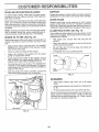
ENGINE
LUBRICATION
Only use high quatity detergent oil rated with API service
classification S F or SG Select the oil's SAE viscosity grade
according to your expected operating temperature°
SAE VISCOSITY GRADES
°F
-20 _
0_
TEMPERATURE
30 °
32"
40"
RANGE ANTICIPATED
60 °
80"
PAPER CARTRIDGE
100 =
AIR CLEANER
BASE
CAP,DIPSTICK
BEFORE NEXT OIL CHANGE
AIR
NOTE: Although multi-viscosity oils (5W30, 10W30 etc.
improve starting in cold weather, these multi-viscosity oils
will result in increased oil consumption when used above
32°F, Check your engine oil level more frequently to avoid
possible engine damage from running low on oil.
Change the oil after the first two hours of operation and
every 50 hours thereafter or at least once a year if the
tractor is not used for 50 hours in one year.
Check the crankcase oil level before starting the engine
and after each eight (8) hours of operation. Tighten oil fiH
cap/dipstick securely each time you check the oil level
PLUG
TO CHANGE ENGINE OIL (See Fig_ 15)
Determine temperature range expected before oil change_
All oil must meet APt service classification SF or SG_
FIG. 15
=
Be sure tractor is on level surfacer
=
o
Oil wit1drain more freely when warm.
Catch oil in a suitable container_
.
Remove oil fill cap/dipstick, Be carefu] not to allow dirt
to enter the engine when changing oil.
Your engine will not run properly using a dirty air filter.
Clean the foam pre-cleaner after every 25 hours of operation or every season. Service paper cartridge every 100
hours of operation or' every season, whichever occurs firsL
=
Remove drain plugo
Service air cleaner more often under dusty conditions.
°
After oil has drained completely, replace oil drain plug
and tighten securely°
o
AIR FILTER
Use gauge on oil fill cap/dipstick for checking level..
Insert dipstick into the tube and rest the oil fill cap on the
tube. Do not thread the cap onto the tube when taking
reading. Keep oil at"FULL" line on dipstick. Tighten
cap onto the tube securely when finished.
AIR SCREEN
Remove knob and cover.
o Remove wing nut and air cleaner from base.
TO SERVICE PRE-CLEANER
Refill engine with oil through oil fill dipstick tube. Pour
slowly. Do not overfill For approximate capacity see
"PRODUCT SPECIFICATIONS"
on page 3 of this
manual
CLEAN
(See Fig. 15)
o
Slide foam pre-cleaner off cartridge
o
Wash it in liquid detergent and water'.
°
Squeeze it dry in a clean cloth_
,
Saturate it in engine oil. Wrap it in clean, absorbent
cloth and squeeze to remove excess oil
TO SERVICE CARTRIDGE
(See Fig, 15)
Air screen must be kept free of dirt and chaff to prevent
engine damage from overheating, Clean with a wire brush
or compressed air to remove dirt and stubborn dried gum
fibers,,
18
o
Gently tap the flat side of the paper' cartridge to dislodge dirt. Do not wash the paper cartridge or use
pressurized air', as this wil! damage the eartridge_
Replace a dirty, bent, or damaged cartridge_
=
Reinstall the pre-cleaner (cleaned and oiled) over the
paper' cartridge.
•
Reassemble air cleaner, wing nut, cover and tighten
knob securely_
, i ii,lllll
¸
CUSTOMER RESPONSUlBIL
ES
, ,i i,im ,llll
CLEAN
AIR INTAKE/COOLING
MUFFLER
AREAS
Inspect and replace corroded muffler and spark arrester (if
equipped) as it could create a fire hazard and/or damage.,
To insure proper cooling, make sure the grass screen,
cooling fins, and other external surfaces of the engine are
kept clean at all times,
SPARK
Every 100 hours of operation (more often under extremely
dusty, dirty conditions), remove the blower housing and
other cooling shrouds. Clean the cooling fins and external
surfaces as necessary. Make sure the cooling shrouds are
reinstalled
Replace spark plugs at the beginning of each mowing
season or after every 100 hours of operation, whichever
occurs first. Spark plug type and gap setting are shown in
"PRODUCT SPECIFICATIONS" on page 3 of this manual.
NOTE: Operating th e engine with a blocked grass screen,
dirty or plugged cooling fins, and/or cooling shrouds removed will cause engine damage due to overheating.
ENGINE
OIL FILTER
IN-LINE
(See Fig. 16)
o
o
(See Fig, 17)
°
With engine cool, remove filter and plug fue! line
sections.
-
Place new fuel filter in position in fuel line with arrow
pointing towards carburetor..
Be sure there are no fuel line leaks and damps are
properly positioned.
Immediately wipe up any spilled gasoline
•
.
Remove oil filter and wipe oft filter adapter_
.
FUEL FILTER
The fuel filter should be replaced once each season. If fuel
filter becomes clogged, obstructing fuel flow to carburetor,
replacement is required..
Replace the engine oil filter every season or every other oil
change if the tractor is used more than 100 hours in one
year.
o
Drain oil from engine crankcase (See "TO CHANGE
ENGINE OIL" in this section of this manual, through
step remove drain plug)
o
PLUGS
Apply a thin coating of new engine oil to the rubber
gasket on replacement oil filter,
CLAMP
Install replacement oil filter on filter adapter, Turn oit
filter clockwise until rubber gasket contacts the filter
adapter, then tighten filter an additional 1/2 turn,
Fill crankcase with new 0il (See "TO CHANGE ENGINE OIL" in this section of this manual). For approximate capacity see "PRODUCT SPECIFICATIONS" on
page 3 of this manual.
CLAMP
FUEL
FILTER
Start the engine and check for oil leaks,, Correct any
leaks before placing engine into full operation,
FIG. 17
CLEANING
o
Clean engine, battery, seat, finish, etc. of alt foreign
matter.
o
Keep finished surfaces and wheels free of all gasoline,
oil, etco
°
Protect painted surfaces with automotive type wax..
We do not recommend using a garden hose to clean your
tractor unless the electrical system, muffler, air filter and
carburetor are covered to keep water out Water in engine
can result in a shortened engine life.,
OIL FILTER
FIG. 16
19
SEIRVmCEAND ADJUSTMENTS
,,r,, ..........................
,,
i i
i
'
CAUTION: BEFORE PERFORMING ANY SERVICE OR ADJUSTMENTS:
o
Depress clutchtbrake pedal fully and set parking brake.
o
Place motion control lever in neutral (N) position.
o
Place attachment clutch in "DISENGAGED"
position.
°
Turn ignition key "OFF" and remove key.
o
Make sure the blades and all moving parts have completely stopped.
o
Disconnect spark plug wire from spark plug and place wire where it cannot come in contact
with plugo
ii,
li i,i
,im
,111i,
i
i
TRACTOR
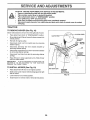
TO REMOVE
MOWER
(See Fig. 18)
Mowerwilt be easier to remove from the right side of tractor
°
,
Place attachment clutch in "DISENGAGED" position.
Move attachment lift lever forward to lower mower to its
lowest position_
o
Roll belt off engine pulley.
o
Disconnect clutch rod from clutch lever by removing
retainer spring_
°
Disconnect anti-sway bar from chassis bracket by
removing retainer spring
o
Disconnect suspension arms from rear deck brackets
by removing retainer springs°
.
Disconnect front links flora deck by removing retainer
springs°
o
Raise lift lever to raise suspension arms, Slide mower
out from under tractor,
SPRING
IMPORTANT:
IF AN ATTACHMENT
OTHER THAN THE
MOWER
iS TO BE MOUNTED
TO THE TRACTOR,
REMOVE THE FRONT LINKS,
TO INSTALL
MOWER
RETAINER
SPRING
(See Fig. 18)
,
Raise attachment lift lever to its highest position,
°
Slide mower under tractor with discharge guard to right
side of tractor.
.
.
Lower lift lever to its lowest position,,
Install mower in reverse order of removal instructions.
ENGINE
PULLEY
SUSPENSION
ANTI-SWAY
BAR
RETAINER
SPRINGS
(BOTH SIDES)
FIG. 18
20
=
ii,u,,
iir-i
',
SERVNCE
........
TO
,,i
LEVEL
,
MOWER
AND
.......................
,r,lllJ,J
HOUSING
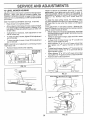
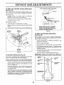
FRONT-TO-BACK ADJUSTMENT (See Figs. 21 and 22)
IMPORTANT: DECK MUST BE LEVEL SIDE-TO-SiDE. IF
THE FOLLOWING FRONT-TO-BACK ADJUSTMENT IS
NECESSARY, BE SURE TO ADJUST BOTH FRONT LINKS
EQUALLY SO MOWER WiLL STAY LEVEL SIDE-TOSIDE,
Adjustthemower whiletractor
isparkedon level
ground or
driveway
Make sure tires are properly inflated (See
"PRODUCT SPECIFICATIONS" on page 3 of this manual)°
If tires are over o r underinflated, you will not properly adjust
your mower..
SIDE-TO-SIDE
ADJUSTMENT
To obtain the best cutting results, the mower housing
should be adiusted so that the front is approximately 1/4" to
3/4" lower than the rear when the mower is in its highest
position,
Check adjustment on right side of tractor,, Measure distance "D" directly in front and behind the mandrel at bottom
edge of mower housing as shown.
°
Before making any necessary adjustments, check that
both front links are equal in length. Both links should be
approximately t0-3/8".
•
If links are not equal in length, adjust one link to same
length as other link
°
To lower front of mower loosen nut "E" on both front
links an equal number of turns.
•
When distance "D" is 1/4" to 3/4" lower at front than
rear, tighten nuts "F" against trunnion on both front
links.
(See Figs. 19 and 20)
o
Raise mower to its highest position.
-
At the midpoint of both sides of mower, measure height
from bottom edge of mowerto ground Distance"A" on
both sides of mower should be the same or within 1/4"
of each other.
•
If adjustment is necessary, make adjustment on one
side of mower only.
o
To raise one side of mower, tighten lift link adjustment
nut on that side
o
To lower one side of mower, loosen lift link adjustment
nut on that side.
NOTE: Each fun turn of adjustment nut will change mower
height about 118".
•
Recheck measurements
after adjusting°
BOTTOM EDGE
OF MOWER TO
GROUND
o
BOTTOM EDGE
OF MOWER TO
GROUND
.
o
GROUND LINE
To raise front of mower, loosen nut "F" from trunnion on
both front links, Tighten nut "E" on both front links an
equal number of turns
When distance "D" is 1/4" to 3/4" lower at front than
rear, tighten nut"F" against trunnion on both front links,,
Recheck side-to-side adjustment.
"
A
_"
;o
,
MANDREL
FIG. 19
J
:?
SUSPENSION
ARM
FIG, 21
BOTH FRONT LINKS MUST BE EQUAL
LIFT LINK
ADJUSTMENT
IN LENGTH
NUT
FIG. 20
NUT
NUT " "_
FRONT LINKS
21
TRUNNION
FIG. 22
SERVICE AND ADJUSTMENTS
TO REPLACE
(See Fig. 23)
MOWER
BLADE
DRIVE
WITH
BELT
PARKING
BRAKE
"ENGAGED"
NUT "A"
,JAM NUT
The mower blade drive belt may be replaced without tools.
Park the tractor on level surface_ Engage parking brake.
BELT REMOVALo
Remove mower from tractor (See "TO REMOVE
MOWER" in this section of this manual)..
o
Work belt off both mandrel pulleys and idler pulleys,
=
Pull belt away from mower,
_,_OPERATING
ARM
BELT INSTALLATION o
Install new belt in reverse order of removal.
=
Make sure belt is in all pulley grooves and inside all belt
guides_
Install mower in reverse order of removal instructions.
•
MANDREL
PULLEY
DO NOT TOUCH THIS NUT. IF FURTHER
BRAKE ADJUSTMENT IS NECESSARY
CONTACT YOUR NEAREST AUTHORIZED
SERVICE CENTER/DEPARTMENT
FIG, 24
IDLER
PULLEYS
TO REPLACE
(See Fig. 25)
MOTION
DRIVE BELT
Park the tractor on level surface Engage parking brake.
For assistance, there is a belt installation guide decal on
bottom side of left footrest.
MANDREL
PULLEY
BRAKE
(See
Remove mower (See "TO REMOVE MOWER" in this
section of this manual,)
,
Remove upper belt keeper..
•
Remove belt from stationary idler and clutching idler,
•
Pull belt slack toward rear of tractor, Carefully remove
belt upwards from transmission input pulley and over
cooling fan blades.
Pull belt toward front of tractor and remove downward
from around engine pulley.
•
FIG. 23
TO ADJUST
o
•
install new belt by reversing above procedure,
IMPORTANT:
MAKE SURE UPPER BELT KEEPER IS
POSITIONED PROPERLY BETWEEN LOCATOR TABS,
Fig. 24)
Your tractor is equipped with an adjustable brake system
which is mounted on the side of the transaxte.
ENGINE_I
PULLEY
Depress clutch/brake pedal and engage parking brake.
°
Measure distance between brake operating arm and
nut "A" on brake rod.,
/
I_.__I
If tractor requires more than six (6) feet stopping distance
at high speed in highest gear, then brake must be adjusted.
,
I
_-]__.(_-_
CLUTCHING _L_-
If distance is other' than 1-3/4", loosen jam nut and turn
nut "A" until distance becomes 1-3/4" Retighten jam
nut against nut "A".
IDLER
H ---_
'
STATIONARY
H
IDLER
Road test tractor for proper stopping distance as stated
above Readjust if necessary, if stopping distance is
still greater than six (6) feet in highest gear', further
maintenance is necessary. Contact your' nearest authorized service center/department.
] _ "-,
_
I
-"--_" UPPER BELT
.....
Kccr'crt
-,hL._C_,r ._
,.PUT
POLLEY
11/" /
FIG. 25
22
TABS
_
IARYI_
TRANSMISSION
.._-" LOCATOR
, i lUl!,!,lll,i
, i,,,11
,,i,
SERVICE AND ADJUSTMENTS
i Ul..., ..........
TO ADJUST
Fig. 26)
NOTION
CONTROL
. .........
LEVER (See
TO REMOVE WHEEL
(See Fig, 27)
The motion control lever has been preset at the factory and
adjustment should not be necessary.
it
i.
FOR REPAIRS
o
Block up axle securely
-
If for any reason the motion control lever will not hold its
position while at a selected speed, it may be adjusted at the
friction pack located on the right side of transmission..
Remove axle cover, retaining ring and washers to allow
wheel removal (rear wheel contains a square key - Do
not lose).
o
Repair tire and reassemble.
o
Park tractor on level surface Stop tractor by turning
ignition key to "OFF" position, and engage parking
brake.
.
On rear wheels only: align grooves in rear wheel hub
and axle. Insert square key.
.
o
Adjust motion control lever by tightening adjustment
Iocknut one half (1/2) turn.
Replace washers and snap retaining ring securely in
axle groove.
.
Replace axle cover.
NOTE: If for any reason the effort to move the motion
control lever becomes too excessive, reverse the above
adjustment procedure by loosening tocknut 1/4to 1/2 turn.
WASHERS
RETAINING
RING
Road test tractor after adjustment and repeat procedure if
necessary
TRANSMISSION
REMOVAL/REPLACEMENT
Should your transmission require removal for service or
replacement, it should be purged after reinstallation and
before operating the tractor. See "PURGE TRANSMISSION" in the Operation section of this manual
AXLE COVER
SQUARE I(EY
(REAR WHEE L ONLY)
FIG. 27
TO START ENGINE WITH A WEAK
See Fig. 28)
BATTERY
CAUTION: Lead-acid batteries generateexplosive gases. Keep sparks, flame
and smoking materials away from batteries.
Always wear eye protection
when around batteries.
If your battery is too weak to start the engine, it should be
recharged.
If "jumper cables" are used for emergency
starting, follow this procedure:
IMPORTANT:
YOUR TRACTOR
IS EQUIPPED
WITH A
12 VOLT NEGATIVE GROUNDED
SYSTEM.
THE OTHER
VEHICLE
MUST ALSO
BE A 12 VOLT
NEGATIVE
GROUNDED
SYSTEM.
DO NOT USE YOUR TRACTOR
BATTERY TO START OTHER VEH!CLES.
ADJUSTMENT
LOGKNUT
FIG. 26
TO ADJUST
STEERING
WHEEL
TO ATTACH JUMPER CABLES o
Connect each end of the RED cable to the POSITIVE
(+) terminal of each battery, taking care not to short
against chassis.
o Connect one end of the BLACK cable to the NEGATIVE (-) terminal of fully charged battery.
•
Connect the other end of the BLACK cable to good
CHASSIS GROUND, away from fuel tank and battery.
ALIGNMENT
If steering wheel crossbars are not horizontal (left to right)
when wheels are positioned straight forward, remove steering wheel and reassemble per instructions in the Assembly
section of this manual.
FRONT WHEEL
TOE-IN/CAMBER
TO REMOVE CABLES, REVERSE ORDER o
BLACK cable first from chassis and then from the fulty
charged battery.
o RED cable last from both batteries
The front wheel toe-in and camber are not adjustable on
your tractor. If damage has occurred to affect the front
wheel toeqn or camber, contact your nearest authorized
service centeddepartment.
23
SERVmCE AND ADJUSTMENTS
,,,,H,=,
=iN l=
=Hill lllili= .................................
=
1,
i
=
TO REPLACE
FUSE
Replace with 30 amp automotive-type plug-in fuse. The
fuse holder' is located behind the dash.
TO REMOVE HOOD
(See Fig. 29)
L,H. PANEL
BOLT
AND GRILL
ASSEMBLY
.
Raise hood.,
°
Unsnap headlight wire connector.
•
Stand in front of tractor. Grasp hood at sides, tilt toward
engine and lift off of tractor°
=
To replace, reverse above procedures
HOOD
....
FIG. 28
!_,iS
:_:
TO REPLACE
HEADLIGHT
BULB
=
Raise hood..
.
Pull bulb holder out of the hole in the backside of the
grill.
-
Replace bulb in holder and push bulb holder securely
back into the hole in the backside of the grill°
Close hood.
.
INTERLOCKS
CONNECTOR
AND RELAYS
FIG. 29
Loose or damaged wiring may cause your tractor to run
poorly, stop running, or p_event it from stalting_
•
HEADLIGHT
WIRE
Check wiring. See electrical wiring diagram in the
Repair Parts section of this rnanual.
24
.... .....u
......
ql_
IIM,
SERWCE AND ADJUSTMENTS
ACCELERATION
ENGINE
•
TO ADJUST
THROTTLE
(See Fig, 30)
CONTROL
CABLE
The throttle control has been preset at the factory and
adjustment should not be necessary, Check adjustment as
described below before loosening cable. If adjustment is
necessary, proceed as follows:
°
o
If holes are not aligned loosen cable clamp screw and
align the holes by inserting a pencil or a 1/4" dr bit
through both holes.
°
Pull throttle cable up to remove slack and tighten cable
clamp screw Remove alignment pencil or drill bit
TO ADJUST
CARBURETOR
-
High speed stop is factory
damage may result
adjusted
CABLE
CLAMP
SCREW
(See Fig. 31)
The carburetor has been preset at the factory and adjustment should nat be necessary, However, minor adjustment may be required to compensate for differences in fuel,
temperature, altitude or load tf the carburetor does need
adjustment, proceed as follows:
SPEED C(
BRACKET
In general, turning the adjusting needles in (clockwise)
decreases the supply of fuel to the engine giving a leaner
fue!/air mixtu re.. Turning the adjusting needles out (counterclockwise) increases the supply of fuel to the engine giving
a richer fuel!air mixture,,
THROTTLE
LEVER
IMPORTANT:
DAMAGE TO THE NEEDLES AND THE
SEATS IN CARBURETOR MAY RESULT 1F NEEDLE IS
TURNED IN TOO TIGHT
FIG. 30
NOTE: The carburetor on this engine is low emission. It is
equipped with an idle fuel adjusting needle with a Iimiter
cap, which allows some adjustment within the limits allowed
by the cap Do not attempt to remove the limiter cap., The
limitercap cannot be removed without breaking the adjusting
needle.
,,
Be sure you have a clean air tilter and the throttle
control cable is adjusted properly (see above),
•
Start engine and allow to warm for.five minutes., Make
adjustments with engine running and shift/motion control
lever in neutral (N) position,
.
Idle speed setting - With throttle control lever in slow
(,,_) position, engine should idle at 1750 RPM, tf
engine idles too s!ow or fast, turn idle speed adjusting
screw in or out until correct idle is attaine&
-
Idle fuel needle settinq - With throttle control lever in
slow (.e_) position, turn idle fuel adjustment needle in
(clockwise) until engine begins to die and then turn out
(counterclockwise) until engine runs rough. Turn needle
to a point midway between those two positions
,,
Do not adjust
-
IMPORTANT:
NEVER
TAMPER
WITH THE ENGINE
GOVERNOR,
WHICH IS FACTORY SET FOR PROPER
ENGINE SPEED
OVERSPEEDINGTHEENGINEABOVE
THE
FACTORY
HIGH
SPEED
SETTING
CAN BE
DANGEROUS,
IF YOU THINK THE ENGINE-GOVERNED
H1GH SPEED NEEDS ADJUSTING,
CONTACT
YOUR
NEAREST
AUTHORIZED
SERVICE
CENTER/
DEPARTMENT,
WHICH HAS PROPER EQUIPMENT
AND
EXPERIENCE,
TO
MAKE
ANY
NECESSARY
ADJUSTMENTS.
With engine not running, move throttle control lever
from slow (-_,) to choke (N) position. Slowly move
lever from choke (1\1) to fast (,_) position..
Check to see if hole in throttle lever and hole in speed
control bracket are aligned
o
TEST
Move throttle control lever from slow (.=_) to fast (._)
position,
if engine hesitates
or dies, turn idle fuel
adjusting needle out (counterclockwise)
1/8 turn° Repeat test and continue to adjust, if necessary,
until
engine accelerates
smoothly,
IDLE SPEED
ADJUSTING
SCREW
IDLE FUEL /
ADJUSTING
iNEEDLE
FIGo 31
Recheck idle speed. Readjust if necessary.
25
STORAGE
Hi,m, n=
,mural
FUEL SYSTEM
TRACTOR
Remove mower from tractor for winter storage_ When
mower is to be stored for a period of time, clean it thoroughly, remove all dirt, grease, leaves, etc. Store in a
clean, dry area,,
o
Inspect and replace belts, if necessary (See belt replacement instructions in the Service and Adjustments
section of this manual).
•
Lubricate as shown in the Customer Responsibilities
section of this manual.
•
Be sure that af! nuts, bolts and screws ate securely
fastened. Inspect moving parts for damage, breakage
and wear° Replace if necessary,.
°
Touch up all rusted or chipped paint surfaces; sand
lightly before painting.
,jj_
IMPORTANT:
1T IS IMPORTANT TO PREVENT GUM
DEPOSITS FROM FORMING _N ESSENTIAL
FUEL
SYSTEM PARTS SUCH AS CARBURETOR, FUEL FILTER,
FUEL HOSE, OR TANK DURING STORAGE,
ALSO,
EXPERIENCE iNDICATES THAT ALCOHOL BLENDED
FUELS (CALLED GASOHOL OR USING ETHANOL OR
METHANOL) CAN ATTRACT MOISTURE WHICH LEADS
TO SEPARATION AND FORMATION OF ACIDS DURING
STORAGE,
ACIDIC GAS CAN DAMAGE THE FUEL
SYSTEM OF AN ENGINE WHILE IN STORAGE,
CAUTION: Never store the tractor with
gasoline in the tank inside a building
where fumes may reach an open flame
or spark. Allow the engine to cool
before storing in any enclosure_
Clean enti[etractor (See"CLEANING"inthe
Customer
Responsibilities section of this manual), ,
i
ENGINE
Immediately prepare your tractor for storage at the end of
the season or if the tractor will not be used for 30 days or
more
o
1' ='n
"
Drain the fuel tank.
.
Start the engine and Iet it run until the fuel lines and
carburetor are empty°
"
Never use engine or carburetor cleaner products in the
fuel tank or permanent damage may occur_
Use fresh fuel next season_
.
NOTE: Fuel stabilizer is an acceptable alternative in
minimizing the formation of fuel gum deposits during storage. Add stabilizer to gasoline in fuel tank or storage
container. Always follow the mix ratio found on stabilizer
container, Run engine at least 10 minutes after adding
stabilizer to allow the stabilizer to reach the carburetor. Do
not drain the gas tank and carburetor' if using fuel stabilizer_
ENGINE
OIL
Drain oil (with engine warm) and replace with clean engine
oil
(See "ENGINE" in the Customer Responsibilities
section of this manual).
BATTERY
°
Fully charge the battery for storage,.
•
After a period of time in storage, battery may require
recharging.
•
Remove spark plug(s)_
•
To help prevent corrosion and power leakage during
long periods of storage, battery cables should,, be
disconnected and battery cleaned thoroughly (see TO
CLEAN BATTERY AND TERMINALS" in the Customer Responsibilities section of this manual)_
°
Pour one ounce of oil through spark plug hole(s) into
cylinder(s),,
•
Turn ignition key to"START" position for a few seconds
to distribute oil,
After cleaning, leave cables disconnected and place
cables where they cannot come in contact with battery
terminats_
=
Replace with new spark plug(s)_
o
Be sure battery drain tube is securely attached,.
=
Do not store gasotine from one season to another,_
o
If battery is removed from tractor for storage, do not
store battery directly on concrete or' damp surfaces.
°
Replace your gasoline can if your can starts to rust.
Rust and/or dirt in your gasoline will cause problems.
.
If possible, store your tractor indoors and cover it to
give protection from dust and dirt,
Q
CYLINDERS
OTHER
o
Cover your tractor with a suitable protective coveithat
does not retain moisture, Do not use plastic. Plastic
cannot breathe which allows condensation to form and
will cause your' tractor to rust.
IMPORTANT: NEVER COVER TRACTOR WHILE ENGINE
AND EXHAUST AREAS ARE STILL WARM.
26
TROUBLESHOOTING
PROBLEM
Will not start
Hard to start
CAUSE
POnNTS
CORRECTION
1
Out of fuel
2
3
4
5
6
7
Engine not "CHOKED" properly
Engine flooded
Bad spark plug
Dirty air filter
Dirty fuel filter
Water in fuel
1
2
3
4
5
6
7
Fill fuel tank
See "TO START ENGINE" in Operation section,
Wait several minutes before attempting to start
Replace spark plug
Clean/replace air filter
Replace fuel filter
Drain fuel tank and carburetor, refill tank with fresh
8
9.
10
Loose or damaged wiring
Carburetor out of adjustment
Engine valves out of adjustment
8
9,
10
gasoline and rep}ace fuel filter
Check all wiring
Contact an authorized service center/department
Conlact an authorized service center/depadment
I
2,
3
4
5
6
7
8
Clean/replace air filter
Replace spark plug
Recharge or replace battery
Replace fuel filler
Drain fuel tank and refill with fresh gasoline
Check all wiring
Contact an authorized service center!department
Contact an authorized service center/department
Depress clutch/brake pedal
Disengage attachment clutch
Recharge or replace battery
Replace fuse
Clean batten/terminals
Check all wiring
Check/replace ignition switch
Check/replace solenoid or starter
Contact an authorized service center/department
1
2
3
Dirty air filter,
Badspark plug
Weak or dead battery
4
5
6,
7
8
Dirty fuel filter
Stale or dirty fue_
Loose or damaged wiring
Carburetor out of adjustment
Engine valves out of adjustment
1
2
Clutch/brake pedal not depressed
Attachment clutch is engaged
3
4
Weak or dead battery
Blown fuse
5
6
7
8
9
Corroded battery terminals
Loose or damaged wiring
Faulty ignition switch
Faulty solenoid or starter
Faulty operator presence switch(as)
1
2
3
4
5
6
7
8
9
Engine clicks but wil! not
start
1
2
3
4
Weak or dead battery
Corroded batter,/terminals
Loose or damaged wiring
Faulty solenoid or starter
t
2
3
4
Recharge or replace battery
Clean battery terminals
Check all wiring
Check/replace solenoid or starter
Loss of power
1
2
3
4
5
6
7
8
9
Cutting too much grass/too fast
Throttle in "CHOKE" position
Build-up of grass, leaves and trash under mower
Dirty air fiiter
Low oil level!dirty oil
Faulty spark plug
Dirty fuel filter
Stale or dirty fuel
Water in fuel
1
2
3
4
5
6
?
8,
9
Set in "Higher Cut" position/reduce
speed
Adjust throttle control
Clean underside of mower housing
Clean!replace air filter
Check oil levetlcllange oil
Clean and regap or change spark plug
Replace fuel filter
Drain fuel tank and refill with fresh gasoline.
Drain fuel tank and carburetor, refill tank with fresh
Engine
will not turn over
10
11
12
13
14
15
t0
11
12
13
t4
15
Spark plug wire loose,
Dirty engine air screen/fins
Dirty/clogged muffler
Loose or damaged wiring
Carburetor out of adjustment
Engine valves out of adjustment
gasoline and replace fuel tilter
Connect and tighten spark plug wire
Clean engine air screenilins,
Clean/replace muffler
Check all wiring
Contact an authorized service center/department
Contact an authorized service center/department
ii, i ,1111,1,
Excessive vibration
1
2
3
Worn, bent or loose blade
Bent blade mandrel,
Loose/damaged part(s)
1
2
3
27
Replace blade
Tighten blade bolt
Replace blade mandrel
Tighten loose part(s) Replace damaged parts
i
TROUBLESHOOTNNG
PROBLEM
CAUSE
Engine continues to run
when operator leaves seat
with attachment clutch
1
PONNTS
CORRECTION
i
Faulty operator-safety
presence control system
1
i
,
i ,i
ii ,IH,I
Check wiring, switches and connections
If not
corrected, contact an authorized service center/
department
engaged
Poor cut - uneven
Mower blades will not
rotate
1
2
Worn, bent or loose blade
Mower deck not level
3
4
Buildup of grass, leaves, and trash under mower
Bent blade mandrel
5
Clogged mower deck vent holes from buildup of
grass, leaves, and trash around mandrels
1
2
3
4
Obstruction in clutch mechanism.
Wornldamaged
mower drive belt
Frozen idler pulley
Frozen blade mandrel
1
2
3
4
Engine speed too stow.
Travel speed too last
Wet grass
Mower deck not revel
1
2
3
4
5
Replace blade Tighten blade bolt
Level mower deck
Clean underside o{mower housing
Rap[ace blade mandrel
C_ean around mandrels to open vent holes
t
2
3
4
Remove
Replace
Replace
Replace
obstruction
mower drive belt
idler pulley
blade mandret
IIIH
Poor grass discharge
5
6
7
8
9
I0
11.
Low/uneven tire air pressure
Worn, bent or loose blade
Buildup of grass, leaves and trash under mowe_
Mower dr{ve belt worn
Blades improperly installed
Improper blades used
Clogged mower deck vent ho_es from buildup of
grass, leaves, and trash around mandrels
1
2.
3.
4
5
6
7
8
9
t0
11
Place throttle contro] in "FAST" position
Shift to stower speed.
Allow grass to dry before mowing
Level mower deck
Check tires for proper air pressure
Replace/sharpen blade Tighten blade bolt
Clean underside of mower housing
Replace mower drive belt
Reinstall blades sharp edge down
Replace with blades listed in this manual
Clean around mandrels to open vent holes
i
Headlight(s) not working
(if so equipped)
Battery will not charge
1
Switch is "OFF"
1
Turn swtteb "ON"
2
3
4
5
Bulb(s) burned out
Faulty light switch
Loose or damaged widng
Blown fuse
2.
3
4
5.
Replace bulb(s)
Check/replace light switch
Check wiring and connections
Replace fuse
1
2
Bad battery cell(s)
Poor cable connections
1.
2.
Replace battery.
Check/clean all connections
3
4
Faulty regulator (if so equipped)
Faulty alternator
3
4.
Replace regulator.
Replace alternator
illlll
Loss of drive
1
2
3
Freewheel control in "disengaged" position
Motion drive belt worn, damaged, or broken
Air trapped in transmission during shipment
or servicing
i ,i,
1_
2
3
Piece freewhee_ controt in "engaged" position
Replace motion drive belt
Purge transmission
i
Engine "backfires"
when turning engine
"OFF"
Engine throttle control not set at "SLOW"
position for 30 seconds before stopping engine
28
i HI Ill
IIII
IHHHHHI,IH,
Move throttle control to "SLOW" position and allow
to idle for 30 seconds before stopping engine.