1
OB346A --1qxp
04.6.14 1:20 PM
Page 1
Revision A:
SPLIT-TYPE, HEAT PUMP AIR CONDITIONERS
● MUZ-A18YV - E1 can be connected to
MCFZ-A18WV - E1 .
● MUZ-A24YV - E1 can be connected to
MCFZ-A24WV - E1 .
Please void OB346.
HFC
utilized
SERVICE MANUAL
R410A
No. OB346
Wireless type
Models
REVISED EDITION-A
MUZ-A18YV MUZ-A24YV MUZ-A26YV -
E1
E1
E1
CONTENTS
Indication of
model name
MUZ-A18YV MUZ-A24YV MUZ-A26YV -
E1
E1
E1
1. TECHNICAL CHANGES ····································2
2. PART NAMES AND FUNCTIONS······················5
3. SPECIFICATION·················································5
4. NOISE CRITERIA CURVES ·······························8
5. OUTLINES AND DIMENSIONS ·························9
6. WIRING DIAGRAM ··········································10
7. REFRIGERANT SYSTEM DIAGRAM ··············12
8. PERFORMANCE CURVES ······························14
9. ACTUATOR CONTROL····································29
10. TROUBLESHOOTING······································30
11. DISASSEMBLY INSTRUCTIONS·····················44
12. PARTS LIST······················································48
NOTE:
This service manual describes technical data of the outdoor units.
•As for indoor units MSZ-A18YV - E1 , MSZ-A24YV - E1 and MSZ-A26YV - E1 , refer to the
service manual OB345.
•As for indoor units MCFZ-A18WV - E1 and MCFZ-A24WV - E1 , refer to the service manual
OB344 REVISED EDITION-A.
OB346A --1qxp
1
04.6.14 1:20 PM
Page 2
TECHNICAL CHANGES
INFORMATION FOR THE AIR CONDITIONER WITH R410A REFRIGERANT
• This room air conditioner adopts an HFC refrigerant (R410A) which never destroys the ozone layer.
• Pay particular attention to the following points, though the basic installation procedure is same as that for R22 air
conditioners.
1 As R410A has working pressure approximate 1.6 times as high as that of R22, some special tools and piping parts/
materials are required. Refer to the table below.
2 Take sufficient care not to allow water and other contaminations to enter the R410A refrigerant during storage and
installation, since it is more susceptible to contaminations than R22.
3 For refrigerant piping, use clean, pressure-proof parts/materials specifically designed for R410A. (Refer to 2. Refrigerant
piping.)
4 Composition change may occur in R410A since it is a mixed refrigerant. When charging, charge liquid refrigerant to prevent
composition change.
New refrigerant
R410A
R22
Composition (Ratio)
HFC-32: HFC-125 (50%:50%)
R22 (100%)
Refrigerant handling
Pseudo-azeotropic refrigerant
Single refrigerant
Not included
Included
A1/A1
A1
Refrigerant
Chlorine
Refrigerant
Safety group (ASHRAE)
Molecular weight
72.6
86.5
Boiling point (:)
-51.4
-40.8
Steam pressure [25:](Mpa)
1.557
0.94
64
44.4
Non combustible
Non combustible
0
0.055
Saturated steam density [25:](Kg/K)
Combustibility
ODP w1
GWP w2
Refrigerant charge method
1730
1700
From liquid phase in cylinder
Gas phase
Possible
Possible
Kind
Incompatible oil
Compatible oil
Color
Non
Light yellow
Non
Non
oil
Refrigerating
Additional charge on leakage
Smell
w1 :Ozone Destruction Parameter : based on CFC-11
w2 :Global Warmth Parameter
: based on CO2
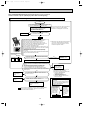
New Specification
Compressor
Previous refrigerant
Current Specification
The incompatible refrigerating oil easily separates from
Since refrigerant and refrigerating oil are compatible each,
refrigerant and is in the upper layer inside the suction muffler. refrigerating oil backs to the compressor through the lower
Raising position of the oil back hole enables to back the
position oil back hole.
refrigerating oil of the upper layer to flow back to the
compressor.
Suction muffler
Suction muffler
Compressor
Oil back hole
Compressor
Refrigerating oil
Oil back hole
Refrigerant
Refrigerating oil /Refrigerant
NOTE : The unit of pressure has been changed to MPa on the international system of units(SI unit system).
f [Gauge])
The conversion factor is: 1(MPa [Gauge]) =10.2(kgf/f
2
OB346A --1qxp
04.6.14 1:20 PM
Page 3
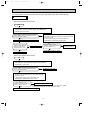
Conversion chart of refrigerant temperature and pressure
(MPa [Gauge])
4.0
Saturated liquid pressure
3.5
R410A
3.0
R22
2.5
2.0
NOTE : The unit of pressure has been changed to MPa on the
international system of units(SI unit system).
1.5
1.0
f [Gauge])
The conversion factor is: 1(MPa [Gauge]) =10.2(kgf/f
0.5
0.0
-0.5
-30 -20 -10
0
10
20
30
40
50
60
(:)
1.Tools dedicated for the air conditioner with R410A refrigerant
The following tools are required for R410A refrigerant. Some R22 tools can be substituted for R410A tools.
The diameter of the service port on the stop valve in outdoor unit has been changed to prevent any other refrigerant being
charged into the unit. Cap size has been changed from 7/16 UNF with 20 threads to 1/2 UNF with 20 threads.
R410A tools
Description
Can R22 tools be used?
Gauge manifold
No
Charge hose
No
Gas leak detector
Torque wrench
R410A has high pressures beyond the measurement range of existing
gauges. Port diameters have been changed to prevent any other refrigerant
from being charged into the unit.
No
Hose material and cap size have been changed to improve the pressure
resistance.
Dedicated for HFC refrigerant.
Yes
6.35 mm and 9.52 mm
No
12.7 mm and 15.88mm
Flare tool
Yes
Clamp bar hole has been enlarged to reinforce the spring strength in the tool.
Flare gauge
Vacuum pump
adapter
Electronic scale for
refrigerant charging
New
Provided for flaring work (to be used with R22 flare tool).
Provided to prevent the back flow of oil. This adapter enables you to use
vacuum pumps.
It is difficult to measure R410A with a charging cylinder because the
refrigerant bubbles due to high pressure and high-speed vaporization
New
New
No : Not Substitutable for R410A
Yes : Substitutable for R410A
2.Refrigerant piping
1 Specifications
Use the refrigerant pipes that meet the following specifications.
Pipe
For liquid
For gas
Outside diameter
mm
Wall
thickness
6.35
0.8 mm
9.52
0.8 mm
Heat resisting foam plastic
12.7
0.8 mm
Specific gravity 0.045 Thickness 8 mm
15.88
1.0 mm
Insulation material
• Use a copper pipe or a copper-alloy seamless pipe with a thickness of 0.8 mm (6.35, 9.52, 12.7), 1.0 mm (15.88).
Never use any pipe with a thickness less than 0.8 mm (6.35, 9.52, 12.7), 1.0 mm (15.88), as the pressure resistance is
insufficient.
3
OB346A --1qxp
04.6.14 1:20 PM
Page 4
2 Flaring work and flare nut
Flaring work for R410A pipe differs from that for R22 pipe.
For details of flaring work, refer to Installation manual “FLARING WORK”.
Dimension of flare nut
Pipe diameter
mm
R410A
R22
6.35
17
17
9.52
22
22
12.7
26
24
15.88
29
27
3.Refrigerant oil
Apply the special refrigeration oil (accessories: packed with indoor unit) to the flare and the union seat surfaces.
4.Air purge
• Do not discharge the refrigerant into the atmosphere.
Take care not to discharge refrigerant into the atmosphere during installation, reinstallation, or repairs to the refrigerant
circuit.
• Use the vacuum pump for air purging for the purpose of environmental protection.
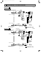
5.Additional charge
For additional charging, charge the refrigerant from liquid phase of the gas cylinder.
If the refrigerant is charged from the gas phase, composition change may occur in the refrigerant inside the cylinder and the
outdoor unit. In this case, ability of the refrigerating cycle decreases or normal operation can be impossible. However,
charging the liquid refrigerant all at once may cause the compressor to be locked. Thus, charge the refrigerant slowly.
Union
Stop valve
Indoor unit
Liquid pipe
Gas pipe
Refrigerant gas
cylinder
operating valve
Outdoor unit
Service port
Gauge manifold
valve (for R410A)
Charge hose (for R410A)
Refrigerant gas cylinder
for R410A with siphon
Refrigerant (liquid)
Electronic scale for refrigerant charging
4
OB346A --1qxp
04.6.14 1:20 PM
2
Page 5
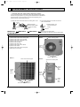
PART NAMES AND FUNCTIONS
MUZ-A18YV - E1
MUZ-A24YV - E1
MUZ-A26YV - E1
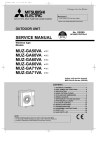
OUTDOOR UNIT
ACCESSORIES
Air inlet
(back and side)
MUZ-A18YV MUZ-A24YV MUZ-A26YV -
Piping
Drain hose
1
Drain socket
1
2
Drain cap [33
2
E1
E1
E1
Air outlet
Drain outlet
3
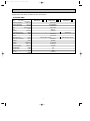
SPECIFICATION
Outdoor model
Function
Capacity
Power supply
Cooling
Heating
Single phase
230V,50Hz
5.0(0.9~5.9)
5.9(0.9~7.8)
2.5
—
2,940/1,650W
2,940/2,210W
20
6.62
1,500
98.5
7.38
1,670
98.4
7.38
6.32
7.08
0.30
3.21
3.41
SNB130FLDH
850
U-V 0.45 W-U 0.45
V-W 0.45
PM8H60-UB
BLK-WHT 15.2
WHT-RED 15.2 RED-BLK15.2
840o850o330
53
53/51W
55/53W
800/480W
800/620W
2
Special
remarks
Fan
motor
Compressor
Electrical
data
Capacity Rated frequency(Min.~Max.)
kW
Dehumidification
r/h
Air flow(High/LowW)
K /h
Power outlet
A
Running current
A
Power input
W
Power factor
%
Starting current ✽1
A
Compressor motor current ✽1
A
Fan motor current
A
Coefficient of performance(C.O.P) ✽1
Model
Output
W
Winding
"
resistance(at 20:)
Model
Winding
"
resistance(at 20:)
mm
Dimensions WOHOD
kg
Weight
Sound level(High/LowW)
dB
rpm
Fan speed(High/LowW)
Fan speed regulator
Refrigerant filling
kg
capacity(R410A)
Refrigerating oil(Model)
cc
Thermistor RT61(at 100:)
k"
Thermistor RT62(at 25:)
k"
Thermistor RT65(at 50:)
k"
Thermistor RT68(at 25:)
k"
MUZ-A18YV - E1
Indoor model
MSZ-A18YV - E1
1.8
450 (NEO22)
13.4
10.0
17.0
10.0
NOTE : Test conditions are based on ISO 5151.
Cooling : Indoor DB 27: WB 19:
Outdoor DB 35: WB (24:)
Heating : Indoor DB 20: WB 15:
Outdoor DB 7: WB 6:
Refrigerant piping length (one way): 5m
✽1 Measured under rated operating frequency.
w Reference value
5
MUZ-A18YV - E1
Indoor model
MCFZ-A18WV - E1
Heating
Cooling
Single phase
230V,50Hz
6.0(0.9~7.5)
4.8(10.9~5.5)
—
2.4
2,940/2,210W
2,940/1,650W
20
8.87
7.76
2,000
1,750
98
8.87
8.57
7.46
0.30
2.88
2.62
SNB130FLDH
850
U-V 0.45 W-U 0.45
V-W 0.45
PM8H60-UB
BLK-WHT 15.2
WHT-RED 15.2 RED-BLK15.2
840o850o330
53
55/53W
53/51W
800/620W
800/480W
2
1.8
450 (NEO22)
13.4
10.0
17.0
10.0
OB346A --1qxp
04.6.14 1:20 PM
Outdoor model
Page 6
MUZ-A24YV - E1
Indoor model
MSZ-A24YV - E1
MUZ-A24YV - E1
Indoor model
MCFZ-A24WV - E1
MUZ-A26YV - E1
Indoor model
MSZ-A26YV - E1
Cooling
Cooling
Heating
Heating
Cooling
Heating
Single phase
Single phase
Single phase
Power supply
230V,50Hz
230V,50Hz
230V,50Hz
Capacity Rated frequency(Min.~Max.) kW
6.0(0.9~6.7) 6.8(0.9~8.1) 5.5(0.9~6.1) 6.4(0.9~7.9) 7.1(0.9~8.3) 8.1(0.9~9.6)
3.1
3.8
—
—
Dehumidification
3.0
—
r/h
Air flow(High/LowW)
K /h 2,940/1,650W 2,940/2,210W 2,940/1,650W 2,940/2,210W 2,940/1,650W 2,940/2,210W
Power outlet
20
20
20
A
Running current
10.38
10.75
10.47
11.42
8.49
A
8.75
Power input
2,340
2,431
2,360
2,581
W
1,921
1,981
Power factor
98.4
98
98.3
%
Starting current ✽1
8.75
10.47
11.42
A
Compressor motor current ✽1
A
10.08
10.45
10.17
11.12
8.19
8.45
Fan motor current
0.30
0.30
0.30
A
Coefficient of performance(C.O.P) ✽1
2.27
2.84
2.62
3.06
3.02
3.32
Model
SNB130FLDH
SNB130FLDH
TNB220FMCH
Output
850
850
1,300
W
Winding
U-V 0.45 W-U 0.45
U-V 0.45 W-U 0.45
U-V 1.41
W-U 1.41
"
resistance(at 20:)
V-W 0.45
V-W 0.45
V-W 1.41
PM8H60-UB
PM8H60-UB
PM8H60-UB
Model
Winding
BLK-WHT 15.2
BLK-WHT 15.2
BLK-WHT 15.2
"
resistance(at 20:)
WHT-RED 15.2 RED-BLK15.2 WHT-RED 15.2 RED-BLK15.2 WHT-RED 15.2 RED-BLK15.2
840o850o330
840o850o330
840o850o330
mm
Dimensions WOHOD
kg
Weight
53
53
58
W
W
W
W
Sound level(High/LowW)
W
dB
53/51
53/51
55/53
55/53W
53/51
55/53
W
W
W
rpm
W
Fan speed(High/LowW)
W
800/480
800/480
800/620
800/620W
800/480
800/620
Fan speed regulator
2
2
2
Refrigerant filling
1.8
2.0
kg
1.8
capacity(R410A)
Refrigerating oil(Model)
450 (NEO22)
450 (NEO22)
870 (NEO22)
cc
Thermistor RT61(at 100:)
13.4
13.4
13.4
k"
Thermistor RT62(at 25:)
10.0
10.0
10.0
k"
Thermistor RT65(at 50:)
17.0
17.0
17.0
k"
Thermistor RT68(at 25:)
10.0
10.0
10.0
k"
NOTE : Test conditions are based on ISO 5151.
Cooling : Indoor DB 27: WB 19:
Outdoor DB 35: WB (24:)
Heating : Indoor DB 20: WB 15:
Outdoor DB 7: WB 6:
Refrigerant piping length (one way): 5m
✽1 Measured under rated operating frequency.
w Reference value
Special
remarks
Fan
motor
Compressor
Electrical
data
Capacity
Function
6
OB346A --1qxp
04.6.14 1:20 PM
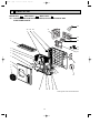
Page 7
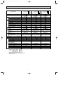
Specifications and rating conditions of main electric parts
OUTDOOR UNIT
Model
Item
MUZ-A24YV -
E1
(CB1,2,3)
Smoothing capacitor
Current transformer
Current transformer
Fuse
MUZ-A18YV -
Fet array
ETQ19Z68AY
(CT61)
ETQ19Z53AY
(F911)
250V 1A
(HC932)
SLA5075
ACB-DB156
(HPS)
Power transistor module
(IPM)
PS21244-A
(L)
340µH 20A
Expansion valve
(LEV)
Power factor controller
(PFC)
Resistor
(R64)
Resistor
(R934A,B)
–
CAM-40YGME 12VDC
CAM-30YGME 12VDC
PS51259-A
10" 20W
1.1" 2W 2%
Resistor
(RS1~4)
0.04" 7W
Solenoid coil relay
(SSR61)
TLP3506
Terminal block
(TB1)
3P
Terminal block
(TB2)
2P
Relay
(X64)
G4A
(21S4)
LD30013
R.V. coil
E1
250V 3.15A
High pressure switch
Reactor
MUZ-A26YV -
560+ 450V
(CT1,2)
(F801, F912)
Fuse
E1
7
OB346A --1qxp
04.6.14 1:20 PM
4
Page 8
NOISE CRITERIA CURVES
MUZ-A18YV - E1
MUZ-A24YV - E1
MUZ-A26YV - E1
SPEED
FUNCTION
SPL(dB(A))
COOLING
53
HEATING
55
LINE
High
OCTAVE BAND SOUND PRESSURE LEVEL, dB re 0.0002 MICRO BAR
Test conditions,
Cooling : Dry-bulb temperature 35: Wet-bulb temperature (24:)
Heating : Dry-bulb temperature 7: Wet-bulb temperature 6:
90
80
70
OUTDOORUNIT
NC-70
60
1m
NC-60
MICROPHONE
50
NC-50
40
NC-40
30
NC-30
20
10
APPROXIMATE
THRESHOLD OF
HEARING FOR
CONTINUOUS
NOISE
63
125
NC-20
250
500
1000
2000
4000
8000
BAND CENTER FREQUENCIES, Hz
8
OB346A --1qxp
04.6.14 1:20 PM
5
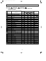
Page 9
OUTLINES AND DIMENSIONS
MUZ-A18YV - E1
MUZ-A24YV - E1
MUZ-A26YV - E1
Unit: mm
OUTDOOR UNIT
REQUIRED SPACE
Open as a rule
500mm or more if
the front and both
sides are open
515
299
40
100mm or more
200mm or more if
there are obstacles
to both sides
51
34
66
360
330
100mm or more
500
840
121
80
Open as a rule
500mm or more if the back,
both sides and top are open
350mm or more
Service panel
155
90
35-
30-
430
850
Liquid refrigerant
pipe joint
Refrigerant pipe
(flared) [6.35 (MUZ-A18/A24YV)
[9.52 (MUZ-A26YV)
198
9
Gas refrigerant
pipe joint
Refrigerant pipe
(flared) [12.7 (MUZ-A18YV)
[15.88 (MUZ-A24/A26YV)
TAB2
BLU
CT61
CN912
1
3
21S4
SYMBOL
MC
MF
NF
NR63
PFC
R64
R934A, B
RS1~4
RT61
RT62
NR63
TAB4
CN901
1 2 3
5
RT68
RT62 RT61
RED
BLK
4 YLW
BLK
BLK
1
LEV
6
CN795
5 6 7
CN702
S
R
CN4
1 2
T801
1 2
CN701
RS2
RS1
SYMBOL
NAME
RT65 FIN TEMPERATURE THERMISTOR
RT68 OUTDOOR HEAT EXCHANGER
TEMPERATURE THERMISTOR
SSR61 SOLENOID COIL RELAY
T801 TRANSFORMER
TB1 TERMINAL BLOCK
TB2 TERMINAL BLOCK
X64 RELAY
21S4 R.V. COIL
7 8
1
3
CN661
1 2 3 4
1 2 3
5
CN781
YLW
RED
NAME
COMPRESSOR
OUTDOOR FAN MOTOR (INNER FUSE)
NOISE FILTER
VARISTOR
POWER FACTOR CONTROLLER
RESISTOR
RESISTOR
RESISTOR
DISCHARGE TEMPERATURE THERMISTOR
DEFROST THERMISTOR
ELECTRONIC
CONTROL
P.C. BOARD
NAME
SMOOTHING CAPACITOR
CURRENT TRANSFORMER
CURRENT TRANSFORMER
FUSE (250V 3.15A)
FUSE (250V 1A)
FUSE (250V 3.15A)
FET ARRAY
POWER TRANSISTOR MODULE
REACTOR
EXPANSION VALVE COIL
N
3
TB2 RED
NOISE FILTER
P.C. BOARD
TO INDOOR
UNIT
CONNECTING
12V
SYMBOL
CB1~3
CT1, 2
CT61
F801
F911
F912
HC932
IPM
L
LEV
PE
GRN
BRN
GRN/YLW
N
LDE1
BLU
GRN
L
NF
F911
R64
BLK
BLK
BLK
CIRCUIT
BREAKER
TB1
SSR61
4
BLK
F912
BLU
BLU
CN902 CN903
2 1 2 1
X64
BLK
2
L
BLK
BLK
BLK
PFC
2 1
CN5
7 6 5 4 3 2 1
CN2
BLK
BLK
POWER SUPPLY
~/N 230V 50Hz
LDE2
3
1
CN601
10
F801
RS4
RS3
LD1
R934B
R934A
3
CB2
CT1 U
CN932
MC
W
RED
RED
WHT
BLK
GRY
PNK
ORN
BLU
YLW
MF
RT65
BLK
U
WHT
V
GRN
LD9 POWER
BOARD
IPM
V
CT2 W
NOTES: 1.About the indoor side electric wiring
refer to the indoor unit electric wiring
diagram for servicing.
2.Use copper conductors only (for field wiring).
3.Symbols below indicate.
:Terminal block
:Connector
1
LD2
CB1
RED
CB3
WHT
CN801
TAB1
HC932
MUZ-A18YV - E1
MUZ-A24YV - E1
OUTDOOR UNIT
CN931
1 2 3 4 5
6
1 2 3
04.6.14 1:20 PM
CN3
1 2
OB346A --1qxp
Page 10
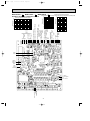
WIRING DIAGRAM
MODELS WIRING DIAGRAM
PE
BLU
CT61
CN912
1
3
21S4
SYMBOL
MC
MF
NF
NR63
PFC
R64
R934A, B
RS1~4
RT61
RT62
RT65
NR63
TAB4
CN901
1 2 3
5
RT62 RT61
CN661
1 2 3 4
1 2 3
5
CN781
YLW
RED
L
RED
BLK
4 YLW
BLK
BLK
1
S
R
CN4
1 2
T801
1 2
CN701
RS2
RS1
NAME
OUTDOOR HEAT EXCHANGER
RT68 TEMPERATURE THERMISTOR
SSR61 SOLENOID COIL RELAY
T801 TRANSFORMER
TB1 TERMINAL BLOCK
TB2 TERMINAL BLOCK
X64 RELAY
21S4 R.V. COIL
SYMBOL
LEV
6
CN795
5 6 7
CN702
3
RT68
7 8
1
NAME
COMPRESSOR
OUTDOOR FAN MOTOR (INNER FUSE)
NOISE FILTER
VARISTOR
POWER FACTOR CONTROLLER
RESISTOR
RESISTOR
RESISTOR
DISCHARGE TEMPERATURE THERMISTOR
DEFROST THERMISTOR
FIN TEMPERATURE THERMISTOR
HPS RED
RED
CN681
1 2
ELECTRONIC
CONTROL
P.C. BOARD
NAME
SMOOTHING CAPACITOR
CURRENT TRANSFORMER
CURRENT TRANSFORMER
FUSE (250V 3.15A)
FUSE (250V 1A)
FUSE (250V 3.15A)
FET ARRAY
HIGH PRESSURE SWITCH
POWER TRANSISTOR MODULE
REACTOR
EXPANSION VALVE COIL
N
3
TB2 RED
NOISE FILTER
P.C. BOARD
TO INDOOR
UNIT
CONNECTING
12V
SYMBOL
CB1~3
CT1, 2
CT61
F801
F911
F912
HC932
HPS
IPM
L
LEV
BRN
GRN/YLW
TAB2
LDE1
N
GRN
BLU
LDE2
L
NF
BLK
BLK
BLK
F911
R64
SSR61
4
BLK
F912
BLU
BLU
CN902 CN903
2 1 2 1
X64
BLK
2
BLK
BLK
BLK
PFC
2 1
CN5
7 6 5 4 3 2 1
CN2
BLK
BLK
CIRCUIT
BREAKER
TB1
GRN
3
1
CN601
11
F801
LD2
CB1
RS4
RS3
LD1
R934B
R934A
3
CB2
CT1 U
CN932
MC
W
RED
RED
WHT
BLK
GRY
PNK
ORN
BLU
YLW
MF
RT65
BLK
U
WHT
V
GRN
LD9 POWER
BOARD
IPM
V
CT2 W
NOTES: 1.About the indoor side electric wiring
refer to the indoor unit electric wiring
diagram for servicing.
2.Use copper conductors only (for field wiring).
3.Symbols below indicate.
:Terminal block
:Connector
1
RED
CB3
WHT
CN801
TAB1
HC932
POWER SUPPLY
~/N 230V 50Hz
CN931
1 2 3 4 5
MUZ-A26YV - E1
OUTDOOR UNIT
1 2 3
04.6.14 1:20 PM
CN3
1 2
OB346A --1qxp
Page 11
MODEL WIRING DIAGRAM
OB346A --1qxp
7
04.6.14 1:20 PM
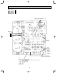
Page 12
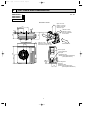
REFRIGERANT SYSTEM DIAGRAM
MUZ-A18YV - E1
MUZ-A24YV - E1
OUTDOOR UNIT
Unit:mm
Refrigerant pipe
[12.7 (MUZ-A18YV)
Muffler
(with heat insulator) [15.88 (MUZ-A24YV) 4-way valve #100
Stop valve
(with service port)
Flared connection
Outdoor
heat
exchanger
Discharge
temperature
thermistor
RT61
Defrost
thermistor
RT62
Compressor
Outdoor heat
exchanger
temperature
thermistor
RT68
Flared connection
Strainer
Receiver #100
Stop valve
LEV
Strainer
#100
Capillary tube
[3.6✕[2.4✕50
Refrigerant pipe [6.35
(with heat insulator)
MUZ-A26YV - E1
OUTDOOR UNIT
Refrigerant pipe [15.88
(with heat insulator)
Refrigerant flow in cooling
Refrigerant flow in heating
Unit:mm
Capillary tube
[1.8✕[0.6✕1000
Oil separator High-pressure
4-way valve
switch
Stop valve
(with service port)
Strainer
#100
Defrost
thermistor
RT62
Discharge
temperature
thermistor
RT61
Flared connection
Compressor
Flared connection
Strainer
Receiver #100
Stop valve
Refrigerant pipe [9.52
(with heat insulator)
R.V. coil
heating ON
cooling OFF
LEV
Capillary tube
[3.6✕[2.4✕50
Strainer
#100
Outdoor
heat
exchanger
Outdoor
heat
exchanger
temperature
thermistor
RT68
R.V. coil
heating ON
cooling OFF
Refrigerant flow in cooling
Refrigerant flow in heating
12
OB346A --1qxp
04.6.14 1:20 PM
Page 13
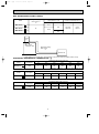
MAX. REFRIGERANT PIPING LENGTH
Refrigerant piping
Model
Piping size O.D : mm
Max. length : m
Gas
A
MUZ-A18YV -
E1
MUZ-A26YV -
E1
Liquid
Indoor unit
6.35
Gas 0.43
Gas 0
Liquid 0.5
Liquid 0
Outdoor unit
12.7
E1
MUZ-A24YV -
Length of connecting pipe : m
30
15.88
9.52
MAX. HEIGHT DIFFERENCE
Indoor
unit
w Max. Height
difference 15m
Refrigerant Piping
Max. length
A
Outdoor unit
w Height difference should be within 15m regardless of which unit, indoor or outdoor position is high.
ADDITIONAL REFRIGERANT CHARGE(R410A : g)
Model
MUZ-A18YV -
E1
Refrigerant piping length (one way)
Outdoor unit
precharged
7m
10m
15m
20m
25m
30m
1,800
0
60
160
260
360
460
Calculation : Xg=20g/m ✕ (Refrigerant piping length (m)–7)
Model
MUZ-A24YV -
E1
Refrigerant piping length (one way)
Outdoor unit
precharged
7m
10m
15m
20m
25m
30m
1,800
0
60
160
260
360
460
Calculation : Xg=20g/m ✕ (Refrigerant piping length (m)–7)
Model
MUZ-A26YV -
E1
Refrigerant piping length (one way)
Outdoor unit
precharged
7m
10m
15m
20m
25m
30m
2,000
0
165
440
715
990
1,265
Calculation : Xg=55g/mo(Refrigerant piping length(m)-7)
13
OB346A --1qxp
8
04.6.14 1:20 PM
Page 14
PERFORMANCE CURVES
MUZ-A18YV - E1
MUZ-A24YV - E1
MUZ-A26YV - E1
The standard data contained in these specifications apply only to the operation of the air conditioner under normal conditions.
Since operating conditions vary according to the areas where these units are installed. The following information has been
provided to clarify the operating characteristics of the air conditioner under the conditions indicated by the performance curve.
(1) GUARANTEED VOLTAGE
207 ~ 253V, 50Hz
(2) AIR FLOW
Air flow should be set at MAX.
(3) MAIN READINGS
(1) Indoor intake air wet-bulb temperature :
°C WB
(2) Indoor outlet air wet-bulb temperature :
°C WB
Cooling
(3) Outdoor intake air dry-bulb temperature :
°C DB
(4) Total input :
W
(5) Indoor intake air dry-bulb temperature :
°C DB
(6) Outdoor intake air wet-bulb temperature :
°C WB
Heating
(7) Total input :
W
Indoor air wet/dry-bulb temperature difference on the left side of the chart on this page and next page shows the difference between the indoor intake air wet/dry-bulb temperature and the indoor outlet air wet/dry-bulb temperature for your
reference at service.
}
}
How to measure the indoor air wet-bulb / dry-bulb temperature difference
1. Attach at least 2 sets of wet and dry-bulb thermometers to the indoor air intake as shown in the figure, and at least 2 sets of
wet and dry-bulb thermometers to the indoor air outlet. The thermometers must be attached to the position where air speed
is high.
2. Attach at least 2 sets of wet and dry-bulb thermometers to the outdoor air intake.
Cover the thermometers to prevent direct rays of the sun.
3. Check that the air filter is cleaned.
4. Open windows and doors of room.
5. Press the EMERGENCY OPERATION switch once (twice) to start the EMERGENCY COOL (HEAT) MODE.
6. When system stabilizes after more than 15 minutes, measure temperature and take an average temperature.
7. 10 minutes later, measure temperature again and check that the temperature does not change.
INDOOR UNIT
OUTDOOR UNIT
11.4
11.1
11.3
12.9
13.9
10.5
10.2
10.3
11.7
12.7
9.5
9.2
9.3
10.6
11.4
8.6
8.3
8.4
9.6
10.3
7.7
7.5
7.5
8.6
9.2
8.1
MSZ-A26YV - E1
MUZ-A26YV - E1
Rated frequency 63Hz
7.6
MCFZ-A24WV - E1
MUZ-A24YV - E1
Rated frequency 102Hz
6.7
MSZ-A24YV - E1
MUZ-A24YV - E1
Rated frequency 88Hz
6.6
MCFZ-A18WV - E1
MUZ-A18YV - E1
Rated frequency 84Hz
6.8
MSZ-A18YV - E1
MUZ-A18YV - E1
Rated frequency 73Hz
Indoor air Wet-bulb temperature
difference (degree)
Wet and dry-bulb
thermometers
Wet and dry-bulb
thermometers
Indoo
r inta
ke air
)
Wet-b
u
lb tem
peratu
re (:
)
Outdoor intake air Dry-bulb temperature (:)
14
ture (:
mpera
bulb te
Wetke air
r inta
Indoo
Outdoor intake air Dry-bulb temperature (:)
Page 15
26.2
29.9
31.2
25.9
24.1
27.6
28.8
ure
23.7
22.1
25.3
26.4
19.8
21.6
20.1
23.0
24.0
17.8
19.4
18.1
20.7
21.6
15.8
17.2
16.1
18.4
19.2
13.8
15.1
14.1
16.1
16.8
11.9
12.9
12.1
13.8
14.4
ea
tak
In
)
Outdoor intake air Wet-bulb temperature (:)
MUZ-A18YV Indoor unit :
MSZ-A18YV -
E1
E1
)
(
Correction of Cooling total input
0
50
100
150 (Hz)
E1
E1
)
(
1.0
0.5
0
50
100
0.5
0
50
100
) (
Correction of Cooling capacity
0
0.5
0
50
100
150 (Hz)
Capacity correction factors
1.0
1.0
0.5
0
50
100
MUZ-A18YV - E1
Indoor unit :
MCFZ-A18WV - E1
) (
1.0
0.5
)
(
E1
)
(
Correction of Cooling total input
1.0
0.5
50
100
150 (Hz)
0
0.5
50
100
50
E1
E1
150 (Hz)
0.5
)
(
MUZ-A24YV Indoor unit :
MSZ-A24YV -
E1
E1
)
Correction of Heating total input
50
100
150 (Hz)
The operational frequency of compressor The operational frequency of compressor The operational frequency of compressor
15
150
1.5
1.0
0
100
The operational frequency of compressor
1.5
1.0
0
MUZ-A24YV Indoor unit :
MSZ-A24YV -
)
0.5
Correction of Heating capacity
1.5
Input correction factors
1.5
0
E1
MUZ-A18YV - E1
Indoor unit :
MCFZ-A18WV - E1
1.0
Input correction factors
E1
Correction of Cooling capacity
MUZ-A24YV Indoor unit :
MSZ-A24YV -
150
1.5
150 (Hz)
Capacity correction factors
(
E1
100
Correction of Heating total input
50
100
150
The operational frequency of compressor The operational frequency of compressor The0 operational
frequency of compressor
MUZ-A24YV Indoor unit :
MSZ-A24YV -
50
The operational frequency of compressor
Correction of Heating capacity
1.5
1.5
Input correction factors
Capacity correction factors
) (
Correction of Cooling total input
1.5
)
0.5
150 (Hz)
Input correction factors
(
MUZ-A18YV - E1
Indoor unit :
MCFZ-A18WV - E1
E1
1.0
The operational frequency of compressor The operational frequency of compressor The operational frequency of compressor
MUZ-A18YV - E1
Indoor unit :
MCFZ-A18WV - E1
E1
1.5
1.0
150 (Hz)
MUZ-A18YV Indoor unit :
MSZ-A18YV -
Correction of Heating total input
1.5
Capacity correction factors
Input correction factors
0.5
MUZ-A18YV Indoor unit :
MSZ-A18YV -
Correction of Heating capacity
1.5
1.0
Outdoor intake air Wet-bulb temperature (:)
NOTE:The above curves are for the heating operation without any frost.
(
1.5
y
ir Dr
ke a
inta
r in
Correction of Cooling capacity
Capacity correction factors
or
Indo
o
do
E1
E1
te
ulb
y-b
r
ir D
te
-bulb
)
re (:
ratu
mpe
mp
Input correction factors
(
MCFZ-A18WV - E1
MUZ-A18YV - E1
Rated frequency 86Hz
MSZ-A24YV - E1
MUZ-A24YV - E1
Rated frequency 96Hz
21.8
MUZ-A18YV Indoor unit :
MSZ-A18 YV -
)
(:
t
era
MSZ-A26YV - E1
MUZ-A26YV - E1
Rated frequency 65Hz
28.0
23.7
MCFZ-A24WV - E1
MUZ-A24YV - E1
Rated frequency 95Hz
25.7
MSZ-A18YV - E1
MUZ-A18YV - E1
Rated frequency 82Hz
Indoor air Dry-bulb temperature
difference (degree)
04.6.14 1:20 PM
Capacity correction factors
OB346A --1qxp
1.0
0.5
0
50
100
150 (Hz)
The operational frequency of compressor
(
04.6.14 1:20 PM
MUZ-A24YV - E1
Indoor unit :
MCFZ-A24WV - E1
Page 16
) (
Correction of Cooling capacity
) (
Correction of Cooling total input
0.5
0
50
100
1.0
0.5
150 (Hz)
) (
0
50
100
0.5
0
50
100
MUZ-A26YV -
E1
1.0
0.5
0
50
100
150 (Hz)
1.0
0.5
0
50
100
0.5
0
100
MUZ-A26YV -
E1
150 (Hz)
E1
Correction of Heating total input
1.5
1.0
0.5
0
150 (Hz)
50
The operational frequency of compressor
Correction of Heating capacity
1.5
Capacity correction factors
Input correction factors
Capacity correction factors
MUZ-A26YV -
E1
Correction of Cooling total input
1.5
Input correction factors
MUZ-A26YV -
Correction of Cooling capacity
1.0
150 (Hz)
The operational frequency of compressor The operational frequency of compressor The operational frequency of compressor
1.5
)
1.5
1.0
150 (Hz)
MUZ-A24YV - E1
Indoor unit :
MCFZ-A24WV - E1
Correction of Heating total input
1.5
Capacity correction factors
1.0
MUZ-A24YV - E1
Indoor unit :
MCFZ-A24WV - E1
Correction of Heating capacity
1.5
Input correction factors
1.5
Capacity correction factors
MUZ-A24YV - E1
Indoor unit :
MCFZ-A24WV - E1
Input correction factors
OB346A --1qxp
50
100
1.0
0.5
150 (Hz)
The operational frequency of compressor The operational frequency of compressor The operational frequency of compressor
0
50
100
150 (Hz)
The operational frequency of compressor
OUTDOOR LOW PRESSURE AND OUTDOOR UNIT CURRENT
<How to operate fixed-frequency operation (Test run operation)>
1. Press the EMERGENCY OPERATION switch to COOL or HEAT mode (COOL : Press once, HEAT : Press twice).
2. Test run operation starts and continue to operate for 30 minutes.
3. Compressor starts at fixed-frequency.
4. Indoor fan operates at High speed.
5. After 30 minutes, test run operation finishes and EMERGENCY OPERATION starts.
6. To cancel test run operation (EMERGENCY OPERATION), press the EMERGENCY OPERATION switch or any button on
remote controller.
NOTE : The unit of pressure has been changed to MPa on the international system of units (SI unit system).
f [Gauge])
The conversion factor is: 1(MPa [Gauge]) =10.2(kgf/f
OUTDOOR LOW PRESSURE AND OUTDOOR UNIT CURRENT
COOL operation
1 Both indoor and outdoor unit are under the
same temperature/humidity condition.
2 Air flow : High speed
3 Operational frequency : 25Hz(MUZ-A18YV)
25Hz(MUZ-A24YV)
24Hz(MUZ-A26YV)
E1
)
(
14
1.4
12
1.2
10
1.0
8
0.8
6
0.6
25Hz
E1
25
60
30
70
MUZ-A18YV - E1
Indoor unit :
MCFZ-A18WV - E1
)
(
(kgf/F [Gauge]) (MPa [Gauge])
16 1.6
25Hz
1.5
50
(
)
2.5
2
20
E1
3
Outdoor unit current(A)
Outdoor low pressure
(kgf/F [Gauge])(MPa [Gauge])
16 1.6
MUZ-A18YV Indoor unit :
MSZ-A18YV -
Relative humidity(%)
14
1.4
12
1.2
10
1.0
8
0.8
6
0.6
MUZ-A18YV - E1
Indoor unit :
MCFZ-A18WV - E1
)
3
25Hz
Outdoor unit current(A)
E1
Outdoor low pressure
(
MUZ-A18YV Indoor unit :
MSZ-A18YV -
Dry-bulb temperature
2.5
25Hz
2
1.5
4 0.4
1
1
15 18 20
25
30 32 35(˚C)
15 18 20
25
30 32 35(˚C)
25
30 32 35(˚C)
18 20
15 18 20
25
30 32 35(˚C)
50
60
70
(%)
50
60
70
(%)
50
60
70
(%)
50
60
70
(%)
Ambient temperature(˚C) Ambient humidity(%) Ambient temperature(˚C) Ambient humidity(%) Ambient temperature(˚C) Ambient humidity(%) Ambient temperature(˚C) Ambient humidity(%)
4
0.4
15
16
(
Page 17
MUZ-A24YV Indoor unit :
MSZ-A24YV -
E1
E1
)
(
14
1.4
25Hz
12
1.2
10
1.0
8
0.8
6
E1
E1
)
0.6
(
MUZ-A24YV - E1
Indoor unit :
MCFZ-A24YV - E1
)
(
(kgf/F [Gauge]) (MPa [Gauge])
16 1.6
5
Outdoor unit current(A)
Outdoor low pressure
(kgf/F [Gauge]) (MPa [Gauge])
16 1.6
MUZ-A24YV Indoor unit :
MSZ-A24YV -
4
25Hz
3
2
14
1.4
12
1.2
10
1.0
8
0.8
6
0.6
MUZ-A24YV - E1
Indoor unit :
MCFZ-A24YV - E1
)
5
25Hz
Outdoor unit current(A)
04.6.14 1:20 PM
Outdoor low pressure
OB346A --1qxp
4
25Hz
3
2
4 0.4
1
1
30 32 35(˚C)
15 18 20
25
30 32 35(˚C)
30 32 35(˚C)
15 18 20
25
25
30 32 35(˚C) 15 18 20
18 20
25
70
(%)
50
60
70
(%)
70
(%)
50
60
50
60
70
(%)
50
60
Ambient temperature(˚C) Ambient humidity(%) Ambient temperature(˚C) Ambient humidity(%) Ambient temperature(˚C) Ambient humidity(%) Ambient temperature(˚C) Ambient humidity(%)
4
0.4
15
MUZ-A26YV -
MUZ-A26YV -
E1
14
1.4
12
1.2
10
1.0
8
0.8
6
0.6
4
0.4
15
E1
4.5
Outdoor unit current(A)
Outdoor low pressure
(kgf/F [Gauge]) (MPa [Gauge])
16 1.6
24Hz
24Hz
4
3.5
3
2.5
30 32 35(˚C)
25
30 32 35(˚C) 15 18 20
18 20
25
70
(%)
50
60
70
(%)
50
60
Ambient temperature(˚C) Ambient humidity(%) Ambient temperature(˚C) Ambient humidity(%)
HEAT operation
Condition indoor: Dry bulb temperature 20.0°C
Wet bulb temperature 14.5°C
Condition outdoor: Dry bulb temperature 2,7,15,20.0°C
Wet bulb temperature 1,6,12,14.5°C
MUZ-A18YV - E1
Indoor unit :
MSZ-A18YV - E1
(
3.5
3.5
3.0
32Hz
2.5
2.0
1.5
2
5
10
15
20
Outdoor unit current (A)
4.0
1.0
25(:)
3.0
32Hz
2.0
1.5
1.0
2
5
10
15
20
Ambient temperature(˚C)
MUZ-A24YV - E1
Indoor unit :
MSZ-A24YV - E1
MUZ-A24YV - E1
Indoor unit :
MCFZ-A24WV - E1
)
)
2.5
Ambient temperature(˚C)
(
(
25(:)
)
MUZ-A26YV -
4.0
4.0
6
3.5
3.5
5.5
3.0
32Hz
2.5
2.0
1.5
1.0
2
5
10
15
20
Ambient temperature(˚C)
25(:)
3.0
32Hz
2.5
2.0
1.5
1.0
E1
32Hz
2
5
10
15
20
Outdoor unit current (A)
Outdoor unit current (A)
)
Outdoor unit current (A)
Outdoor unit current (A)
(
4.0
MUZ-A18YV - E1
Indoor unit :
MCFZ-A18WV - E1
Operational frequency : 32Hz(MUZ-A18YV)
32Hz(MUZ-A24YV)
32Hz(MUZ-A26YV)
25(:)
5
4.5
4.0
3.5
3.0
2
5
10
15
20
Ambient temperature(˚C)
Ambient temperature(˚C)
17
25(:)
OB346A --1qxp
04.6.14 1:20 PM
Page 18
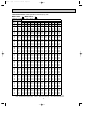
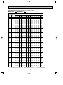
PERFORMANCE DATA COOL operation Rated frequency 73Hz
MSZ-A18YV - E1 : MUZ-A18YV - E1
CAPACITY:5.0(kW)
SHF:0.65
INPUT:1560(W)
21
INDOOR INDOOR
DB(:) WB(:) Q SHC SHF INPUT
21
18
5.88 2.76 0.47 1248
21
20
6.13 2.14 0.35 1310
22
18
5.88 3.00 0.51 1248
22
20
6.13 2.39 0.39 1310
22
22
6.38 1.72 0.27 1357
23
18
5.88 3.23 0.55 1248
23
20
6.13 2.63 0.43 1310
23
22
6.38 1.98 0.31 1357
24
18
5.88 3.47 0.59 1248
24
20
6.13 2.88 0.47 1310
24
22
6.38 2.23 0.35 1357
24
24
6.70 1.54 0.23 1420
25
18
5.88 3.70 0.63 1248
25
20
6.13 3.12 0.51 1310
25
22
6.38 2.49 0.39 1357
25
24
6.70 1.81 0.27 1420
26
18
5.88 3.94 0.67 1248
26
20
6.13 3.37 0.55 1310
26
22
6.38 2.74 0.43 1357
26
24
6.70 2.08 0.31 1420
26
26
6.90 1.31 0.19 1498
27
18
5.88 4.17 0.71 1248
27
20
6.13 3.61 0.59 1310
27
22
6.38 3.00 0.47 1357
27
24
6.70 2.35 0.35 1420
27
26
6.90 1.59 0.23 1498
28
18
5.88 4.41 0.75 1248
28
20
6.13 3.86 0.63 1310
28
22
6.38 3.25 0.51 1357
28
24
6.70 2.61 0.39 1420
28
26
6.90 1.86 0.27 1498
29
18
5.88 4.64 0.79 1248
29
20
6.13 4.10 0.67 1310
29
22
6.38 3.51 0.55 1357
29
24
6.70 2.88 0.43 1420
29
26
6.90 2.14 0.31 1498
30
18
5.88 4.88 0.83 1248
30
20
6.13 4.35 0.71 1310
30
22
6.38 3.76 0.59 1357
30
24
6.70 3.15 0.47 1420
30
26
6.90 2.42 0.35 1498
31
18
5.88 5.11 0.87 1248
31
20
6.13 4.59 0.75 1310
31
22
6.38 4.02 0.63 1357
31
24
6.70 3.42 0.51 1420
31
26
6.90 2.69 0.39 1498
32
18
5.88 5.35 0.91 1248
32
20
6.13 4.84 0.79 1310
32
22
6.38 4.27 0.67 1357
32
24
6.70 3.69 0.55 1420
32
26
6.90 2.97 0.43 1498
NOTE
Q : Total capacity (kW)
SHC : Sensible heat capacity (kW)
OUTDOOR DB(:)
25
27
30
Q SHC SHF INPUT Q SHC SHF INPUT Q SHC SHF INPUT
5.63 2.64 0.47 1310 5.40 2.54 0.47 1373 5.20 2.44 0.47 1435
5.88 2.06 0.35 1388 5.70 2.00 0.35 1420 5.50 1.93 0.35 1482
5.63 2.87 0.51 1310 5.40 2.75 0.51 1373 5.20 2.65 0.51 1435
5.88 2.29 0.39 1388 5.70 2.22 0.39 1420 5.50 2.15 0.39 1482
6.15 1.66 0.27 1443 6.00 1.62 0.27 1482 5.75 1.55 0.27 1544
5.63 3.09 0.55 1310 5.40 2.97 0.55 1373 5.20 2.86 0.55 1435
5.88 2.53 0.43 1388 5.70 2.45 0.43 1420 5.50 2.37 0.43 1482
6.15 1.91 0.31 1443 6.00 1.86 0.31 1482 5.75 1.78 0.31 1544
5.63 3.32 0.59 1310 5.40 3.19 0.59 1373 5.20 3.07 0.59 1435
5.88 2.76 0.47 1388 5.70 2.68 0.47 1420 5.50 2.59 0.47 1482
6.15 2.15 0.35 1443 6.00 2.10 0.35 1482 5.75 2.01 0.35 1544
6.45 1.48 0.23 1498 6.30 1.45 0.23 1544 6.10 1.40 0.23 1622
5.63 3.54 0.63 1310 5.40 3.40 0.63 1373 5.20 3.28 0.63 1435
5.88 3.00 0.51 1388 5.70 2.91 0.51 1420 5.50 2.81 0.51 1482
6.15 2.40 0.39 1443 6.00 2.34 0.39 1482 5.75 2.24 0.39 1544
6.45 1.74 0.27 1498 6.30 1.70 0.27 1544 6.10 1.65 0.27 1622
5.63 3.77 0.67 1310 5.40 3.62 0.67 1373 5.20 3.48 0.67 1435
5.88 3.23 0.55 1388 5.70 3.14 0.55 1420 5.50 3.03 0.55 1482
6.15 2.64 0.43 1443 6.00 2.58 0.43 1482 5.75 2.47 0.43 1544
6.45 2.00 0.31 1498 6.30 1.95 0.31 1544 6.10 1.89 0.31 1622
6.70 1.27 0.19 1576 6.60 1.25 0.19 1622 6.40 1.22 0.19 1669
5.63 3.99 0.71 1310 5.40 3.83 0.71 1373 5.20 3.69 0.71 1435
5.88 3.47 0.59 1388 5.70 3.36 0.59 1420 5.50 3.25 0.59 1482
6.15 2.89 0.47 1443 6.00 2.82 0.47 1482 5.75 2.70 0.47 1544
6.45 2.26 0.35 1498 6.30 2.21 0.35 1544 6.10 2.14 0.35 1622
6.70 1.54 0.23 1576 6.60 1.52 0.23 1622 6.40 1.47 0.23 1669
5.63 4.22 0.75 1310 5.40 4.05 0.75 1373 5.20 3.90 0.75 1435
5.88 3.70 0.63 1388 5.70 3.59 0.63 1420 5.50 3.47 0.63 1482
6.15 3.14 0.51 1443 6.00 3.06 0.51 1482 5.75 2.93 0.51 1544
6.45 2.52 0.39 1498 6.30 2.46 0.39 1544 6.10 2.38 0.39 1622
6.70 1.81 0.27 1576 6.60 1.78 0.27 1622 6.40 1.73 0.27 1669
5.63 4.44 0.79 1310 5.40 4.27 0.79 1373 5.20 4.11 0.79 1435
5.88 3.94 0.67 1388 5.70 3.82 0.67 1420 5.50 3.69 0.67 1482
6.15 3.38 0.55 1443 6.00 3.30 0.55 1482 5.75 3.16 0.55 1544
6.45 2.77 0.43 1498 6.30 2.71 0.43 1544 6.10 2.62 0.43 1622
6.70 2.08 0.31 1576 6.60 2.05 0.31 1622 6.40 1.98 0.31 1669
5.63 4.67 0.83 1310 5.40 4.48 0.83 1373 5.20 4.32 0.83 1435
5.88 4.17 0.71 1388 5.70 4.05 0.71 1420 5.50 3.91 0.71 1482
6.15 3.63 0.59 1443 6.00 3.54 0.59 1482 5.75 3.39 0.59 1544
6.45 3.03 0.47 1498 6.30 2.96 0.47 1544 6.10 2.87 0.47 1622
6.70 2.35 0.35 1576 6.60 2.31 0.35 1622 6.40 2.24 0.35 1669
5.63 4.89 0.87 1310 5.40 4.70 0.87 1373 5.20 4.52 0.87 1435
5.88 4.41 0.75 1388 5.70 4.28 0.75 1420 5.50 4.13 0.75 1482
6.15 3.87 0.63 1443 6.00 3.78 0.63 1482 5.75 3.62 0.63 1544
6.45 3.29 0.51 1498 6.30 3.21 0.51 1544 6.10 3.11 0.51 1622
6.70 2.61 0.39 1576 6.60 2.57 0.39 1622 6.40 2.50 0.39 1669
5.63 5.12 0.91 1310 5.40 4.91 0.91 1373 5.20 4.73 0.91 1435
5.88 4.64 0.79 1388 5.70 4.50 0.79 1420 5.50 4.35 0.79 1482
6.15 4.12 0.67 1443 6.00 4.02 0.67 1482 5.75 3.85 0.67 1544
6.45 3.55 0.55 1498 6.30 3.47 0.55 1544 6.10 3.36 0.55 1622
6.70 2.88 0.43 1576 6.60 2.84 0.43 1622 6.40 2.75 0.43 1669
SHF : Sensible heat factor
DB : Dry-bulb temperature
INPUT : Total power input (W) WB : Wet-bulb temperature
18
OB346A --1qxp
04.6.14 1:20 PM
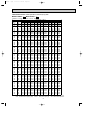
Page 19
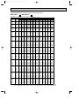
PERFORMANCE DATA COOL operation Rated frequency 73Hz
MSZ-A18YV - E1 : MUZ-A18YV - E1
CAPACITY : 5.0(kW) SHF : 0.65
INDOOR INDOOR
DB(:) WB(:)
21
21
22
22
22
23
23
23
24
24
24
24
25
25
25
25
26
26
26
26
26
27
27
27
27
27
28
28
28
28
28
29
29
29
29
29
30
30
30
30
30
31
31
31
31
31
32
32
32
32
32
NOTE
18
20
18
20
22
18
20
22
18
20
22
24
18
20
22
24
18
20
22
24
26
18
20
22
24
26
18
20
22
24
26
18
20
22
24
26
18
20
22
24
26
18
20
22
24
26
18
20
22
24
26
Q
4.90
5.15
4.90
5.15
5.45
4.90
5.15
5.45
4.90
5.15
5.45
5.75
4.90
5.15
5.45
5.75
4.90
5.15
5.45
5.75
6.05
4.90
5.15
5.45
5.75
6.05
4.90
5.15
5.45
5.75
6.05
4.90
5.15
5.45
5.75
6.05
4.90
5.15
5.45
5.75
6.05
4.90
5.15
5.45
5.75
6.05
4.90
5.15
5.45
5.75
6.05
INPUT : 1560(W)
OUTDOOR DB(:)
35
40
SHC SHF INPUT Q SHC SHF INPUT
2.30 0.47 1529 4.50 2.12 0.47 1622
1.80 0.35 1591 4.80 1.68 0.35 1669
2.50 0.51 1529 4.50 2.30 0.51 1622
2.01 0.39 1591 4.80 1.87 0.39 1669
1.47 0.27 1654 5.10 1.38 0.27 1747
2.70 0.55 1529 4.50 2.48 0.55 1622
2.21 0.43 1591 4.80 2.06 0.43 1669
1.69 0.31 1654 5.10 1.58 0.31 1747
2.89 0.59 1529 4.50 2.66 0.59 1622
2.42 0.47 1591 4.80 2.26 0.47 1669
1.91 0.35 1654 5.10 1.79 0.35 1747
1.32 0.23 1716 5.40 1.24 0.23 1794
3.09 0.63 1529 4.50 2.84 0.63 1622
2.63 0.51 1591 4.80 2.45 0.51 1669
2.13 0.39 1654 5.10 1.99 0.39 1747
1.55 0.27 1716 5.40 1.46 0.27 1794
3.28 0.67 1529 4.50 3.02 0.67 1622
2.83 0.55 1591 4.80 2.64 0.55 1669
2.34 0.43 1654 5.10 2.19 0.43 1747
1.78 0.31 1716 5.40 1.67 0.31 1794
1.15 0.19 1778 5.70 1.08 0.19 1856
3.48 0.71 1529 4.50 3.20 0.71 1622
3.04 0.59 1591 4.80 2.83 0.59 1669
2.56 0.47 1654 5.10 2.40 0.47 1747
2.01 0.35 1716 5.40 1.89 0.35 1794
1.39 0.23 1778 5.70 1.31 0.23 1856
3.68 0.75 1529 4.50 3.38 0.75 1622
3.24 0.63 1591 4.80 3.02 0.63 1669
2.78 0.51 1654 5.10 2.60 0.51 1747
2.24 0.39 1716 5.40 2.11 0.39 1794
1.63 0.27 1778 5.70 1.54 0.27 1856
3.87 0.79 1529 4.50 3.56 0.79 1622
3.45 0.67 1591 4.80 3.22 0.67 1669
3.00 0.55 1654 5.10 2.81 0.55 1747
2.47 0.43 1716 5.40 2.32 0.43 1794
1.88 0.31 1778 5.70 1.77 0.31 1856
4.07 0.83 1529 4.50 3.74 0.83 1622
3.66 0.71 1591 4.80 3.41 0.71 1669
3.22 0.59 1654 5.10 3.01 0.59 1747
2.70 0.47 1716 5.40 2.54 0.47 1794
2.12 0.35 1778 5.70 2.00 0.35 1856
4.26 0.87 1529 4.50 3.92 0.87 1622
3.86 0.75 1591 4.80 3.60 0.75 1669
3.43 0.63 1654 5.10 3.21 0.63 1747
2.93 0.51 1716 5.40 2.75 0.51 1794
2.36 0.39 1778 5.70 2.22 0.39 1856
4.46 0.91 1529 4.50 4.10 0.91 1622
4.07 0.79 1591 4.80 3.79 0.79 1669
3.65 0.67 1654 5.10 3.42 0.67 1747
3.16 0.55 1716 5.40 2.97 0.55 1794
2.60 0.43 1778 5.70 2.45 0.43 1856
Q : Total capacity (kW)
SHC : Sensible heat capacity (kW)
Q
4.33
4.63
4.33
4.63
4.93
4.33
4.63
4.93
4.33
4.63
4.93
5.25
4.33
4.63
4.93
5.25
4.33
4.63
4.93
5.25
5.53
4.33
4.63
4.93
5.25
5.53
4.33
4.63
4.93
5.25
5.53
4.33
4.63
4.93
5.25
5.53
4.33
4.63
4.93
5.25
5.53
4.33
4.63
4.93
5.25
5.53
4.33
4.63
4.93
5.25
5.53
SHF : Sensible heat factor
INPUT : Total power input (W)
19
SHC
2.03
1.62
2.21
1.80
1.33
2.38
1.99
1.53
2.55
2.17
1.72
1.21
2.72
2.36
1.92
1.42
2.90
2.54
2.12
1.63
1.05
3.07
2.73
2.31
1.84
1.27
3.24
2.91
2.51
2.05
1.49
3.42
3.10
2.71
2.26
1.71
3.59
3.28
2.91
2.47
1.93
3.76
3.47
3.10
2.68
2.15
3.94
3.65
3.30
2.89
2.38
43
SHF INPUT
0.47 1654
0.35 1716
0.51 1654
0.39 1716
0.27 1778
0.55 1654
0.43 1716
0.31 1778
0.59 1654
0.47 1716
0.35 1778
0.23 1833
0.63 1654
0.51 1716
0.39 1778
0.27 1833
0.67 1654
0.55 1716
0.43 1778
0.31 1833
0.19 1895
0.71 1654
0.59 1716
0.47 1778
0.35 1833
0.23 1895
0.75 1654
0.63 1716
0.51 1778
0.39 1833
0.27 1895
0.79 1654
0.67 1716
0.55 1778
0.43 1833
0.31 1895
0.83 1654
0.71 1716
0.59 1778
0.47 1833
0.35 1895
0.87 1654
0.75 1716
0.63 1778
0.51 1833
0.39 1895
0.91 1654
0.79 1716
0.67 1778
0.55 1833
0.43 1895
DB : Dry-bulb temperature
WB : Wet-bulb temperature
OB346A --1qxp
04.6.14 1:20 PM
Page 20
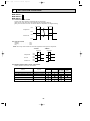
PERFORMANCE DATA COOL operation Rated frequency 84Hz
MCFZ-A18WV - E1 : MUZ-A18YV - E1
CAPACITY:4.8(kW)
SHF:0.65
INPUT:1830(W)
OUTDOOR
INDOOR INDOOR
DB(:) WB(:)
21
21
22
22
22
23
23
23
24
24
24
24
25
25
25
25
26
26
26
26
26
27
27
27
27
27
28
28
28
28
28
29
29
29
29
29
30
30
30
30
30
31
31
31
31
31
32
32
32
32
32
NOTE
18
20
18
20
22
18
20
22
18
20
22
24
18
20
22
24
18
20
22
24
26
18
20
22
24
26
18
20
22
24
26
18
20
22
24
26
18
20
22
24
26
18
20
22
24
26
18
20
22
24
26
Q
5.64
5.88
5.64
5.88
6.12
5.64
5.88
6.12
5.64
5.88
6.12
6.43
5.64
5.88
6.12
6.43
5.64
5.88
6.12
6.43
6.62
5.64
5.88
6.12
6.43
6.62
5.64
5.88
6.12
6.43
6.62
5.64
5.88
6.12
6.43
6.62
5.64
5.88
6.12
6.43
6.62
5.64
5.88
6.12
6.43
6.62
5.64
5.88
6.12
6.43
6.62
21
25
SHC SHF INPUT Q SHC SHF
2.65 0.47 1464 5.40 2.54 0.47
2.06 0.35 1537 5.64 1.97 0.35
2.88 0.51 1464 5.40 2.75 0.51
2.29 0.39 1537 5.64 2.20 0.39
1.65 0.27 1592 5.90 1.59 0.27
3.10 0.55 1464 5.40 2.97 0.55
2.53 0.43 1537 5.64 2.43 0.43
1.90 0.31 1592 5.90 1.83 0.31
3.33 0.59 1464 5.40 3.19 0.59
2.76 0.47 1537 5.64 2.65 0.47
2.14 0.35 1592 5.90 2.07 0.35
1.48 0.23 1665 6.19 1.42 0.23
3.55 0.63 1464 5.40 3.40 0.63
3.00 0.51 1537 5.64 2.88 0.51
2.39 0.39 1592 5.90 2.30 0.39
1.74 0.27 1665 6.19 1.67 0.27
3.78 0.67 1464 5.40 3.62 0.67
3.23 0.55 1537 5.64 3.10 0.55
2.63 0.43 1592 5.90 2.54 0.43
1.99 0.31 1665 6.19 1.92 0.31
1.26 0.19 1757 6.43 1.22 0.19
4.00 0.71 1464 5.40 3.83 0.71
3.47 0.59 1537 5.64 3.33 0.59
2.88 0.47 1592 5.90 2.77 0.47
2.25 0.35 1665 6.19 2.17 0.35
1.52 0.23 1757 6.43 1.48 0.23
4.23 0.75 1464 5.40 4.05 0.75
3.70 0.63 1537 5.64 3.55 0.63
3.12 0.51 1592 5.90 3.01 0.51
2.51 0.39 1665 6.19 2.41 0.39
1.79 0.27 1757 6.43 1.74 0.27
4.46 0.79 1464 5.40 4.27 0.79
3.94 0.67 1537 5.64 3.78 0.67
3.37 0.55 1592 5.90 3.25 0.55
2.77 0.43 1665 6.19 2.66 0.43
2.05 0.31 1757 6.43 1.99 0.31
4.68 0.83 1464 5.40 4.48 0.83
4.17 0.71 1537 5.64 4.00 0.71
3.61 0.59 1592 5.90 3.48 0.59
3.02 0.47 1665 6.19 2.91 0.47
2.32 0.35 1757 6.43 2.25 0.35
4.91 0.87 1464 5.40 4.70 0.87
4.41 0.75 1537 5.64 4.23 0.75
3.86 0.63 1592 5.90 3.72 0.63
3.28 0.51 1665 6.19 3.16 0.51
2.58 0.39 1757 6.43 2.51 0.39
5.13 0.91 1464 5.40 4.91 0.91
4.65 0.79 1537 5.64 4.46 0.79
4.10 0.67 1592 5.90 3.96 0.67
3.54 0.55 1665 6.19 3.41 0.55
2.85 0.43 1757 6.43 2.77 0.43
Q : Total capacity (kW)
SHC : Sensible heat capacity (kW)
DB(:)
27
INPUT Q SHC SHF
1537 5.18 2.44 0.47
1629 5.47 1.92 0.35
1537 5.18 2.64 0.51
1629 5.47 2.13 0.39
1693 5.76 1.56 0.27
1537 5.18 2.85 0.55
1629 5.47 2.35 0.43
1693 5.76 1.79 0.31
1537 5.18 3.06 0.59
1629 5.47 2.57 0.47
1693 5.76 2.02 0.35
1757 6.05 1.39 0.23
1537 5.18 3.27 0.63
1629 5.47 2.79 0.51
1693 5.76 2.25 0.39
1757 6.05 1.63 0.27
1537 5.18 3.47 0.67
1629 5.47 3.01 0.55
1693 5.76 2.48 0.43
1757 6.05 1.87 0.31
1848 6.34 1.20 0.19
1537 5.18 3.68 0.71
1629 5.47 3.23 0.59
1693 5.76 2.71 0.47
1757 6.05 2.12 0.35
1848 6.34 1.46 0.23
1537 5.18 3.89 0.75
1629 5.47 3.45 0.63
1693 5.76 2.94 0.51
1757 6.05 2.36 0.39
1848 6.34 1.71 0.27
1537 5.18 4.10 0.79
1629 5.47 3.67 0.67
1693 5.76 3.17 0.55
1757 6.05 2.60 0.43
1848 6.34 1.96 0.31
1537 5.18 4.30 0.83
1629 5.47 3.89 0.71
1693 5.76 3.40 0.59
1757 6.05 2.84 0.47
1848 6.34 2.22 0.35
1537 5.18 4.51 0.87
1629 5.47 4.10 0.75
1693 5.76 3.63 0.63
1757 6.05 3.08 0.51
1848 6.34 2.47 0.39
1537 5.18 4.72 0.91
1629 5.47 4.32 0.79
1693 5.76 3.86 0.67
1757 6.05 3.33 0.55
1848 6.34 2.72 0.43
SHF : Sensible heat factor
INPUT : Total power input (W)
20
INPUT
1610
1665
1610
1665
1739
1610
1665
1739
1610
1665
1739
1812
1610
1665
1739
1812
1610
1665
1739
1812
1903
1610
1665
1739
1812
1903
1610
1665
1739
1812
1903
1610
1665
1739
1812
1903
1610
1665
1739
1812
1903
1610
1665
1739
1812
1903
1610
1665
1739
1812
1903
Q
4.99
5.28
4.99
5.28
5.52
4.99
5.28
5.52
4.99
5.28
5.52
5.86
4.99
5.28
5.52
5.86
4.99
5.28
5.52
5.86
6.14
4.99
5.28
5.52
5.86
6.14
4.99
5.28
5.52
5.86
6.14
4.99
5.28
5.52
5.86
6.14
4.99
5.28
5.52
5.86
6.14
4.99
5.28
5.52
5.86
6.14
4.99
5.28
5.52
5.86
6.14
SHC
2.35
1.85
2.55
2.06
1.49
2.75
2.27
1.71
2.95
2.48
1.93
1.35
3.14
2.69
2.15
1.58
3.34
2.90
2.37
1.82
1.17
3.54
3.12
2.59
2.05
1.41
3.74
3.33
2.82
2.28
1.66
3.94
3.54
3.04
2.52
1.90
4.14
3.75
3.26
2.75
2.15
4.34
3.96
3.48
2.99
2.40
4.54
4.17
3.70
3.22
2.64
DB : Dry-bulb temperature
WB : Wet-bulb temperature
30
SHF INPUT
0.47 1684
0.35 1739
0.51 1684
0.39 1739
0.27 1812
0.55 1684
0.43 1739
0.31 1812
0.59 1684
0.47 1739
0.35 1812
0.23 1903
0.63 1684
0.51 1739
0.39 1812
0.27 1903
0.67 1684
0.55 1739
0.43 1812
0.31 1903
0.19 1958
0.71 1684
0.59 1739
0.47 1812
0.35 1903
0.23 1958
0.75 1684
0.63 1739
0.51 1812
0.39 1903
0.27 1958
0.79 1684
0.67 1739
0.55 1812
0.43 1903
0.31 1958
0.83 1684
0.71 1739
0.59 1812
0.47 1903
0.35 1958
0.87 1684
0.75 1739
0.63 1812
0.51 1903
0.39 1958
0.91 1684
0.79 1739
0.67 1812
0.55 1903
0.43 1958
OB346A --1qxp
04.6.14 1:20 PM
Page 21
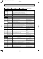
PERFORMANCE DATA COOL operation Rated frequency 84Hz
MCFZ-A18WV - E1 : MUZ-A18YV - E1
CAPACITY : 4.8(kW) SHF : 0.65
INPUT : 1830(W)
OUTDOOR DB(:)
INDOOR INDOOR
35
40
DB(:) WB(:) Q SHC SHF INPUT Q SHC SHF INPUT Q
21
18
4.70 2.21 0.47 1793 4.32 2.03 0.47 1903 4.15
21
20
4.94 1.73 0.35 1867 4.61 1.61 0.35 1958 4.44
22
18
4.70 2.40 0.51 1793 4.32 2.20 0.51 1903 4.15
22
20
4.94 1.93 0.39 1867 4.61 1.80 0.39 1958 4.44
22
22
5.23 1.41 0.27 1940 4.90 1.32 0.27 2050 4.73
23
18
4.70 2.59 0.55 1793 4.32 2.38 0.55 1903 4.15
23
20
4.94 2.13 0.43 1867 4.61 1.98 0.43 1958 4.44
23
22
5.23 1.62 0.31 1940 4.90 1.52 0.31 2050 4.73
24
18
4.70 2.78 0.59 1793 4.32 2.55 0.59 1903 4.15
24
20
4.94 2.32 0.47 1867 4.61 2.17 0.47 1958 4.44
24
22
5.23 1.83 0.35 1940 4.90 1.71 0.35 2050 4.73
24
24
5.52 1.27 0.23 2013 5.18 1.19 0.23 2105 5.04
25
18
4.70 2.96 0.63 1793 4.32 2.72 0.63 1903 4.15
25
20
4.94 2.52 0.51 1867 4.61 2.35 0.51 1958 4.44
25
22
5.23 2.04 0.39 1940 4.90 1.91 0.39 2050 4.73
25
24
5.52 1.49 0.27 2013 5.18 1.40 0.27 2105 5.04
26
18
4.70 3.15 0.67 1793 4.32 2.89 0.67 1903 4.15
26
20
4.94 2.72 0.55 1867 4.61 2.53 0.55 1958 4.44
26
22
5.23 2.25 0.43 1940 4.90 2.11 0.43 2050 4.73
26
24
5.52 1.71 0.31 2013 5.18 1.61 0.31 2105 5.04
26
26
5.81 1.10 0.19 2086 5.47 1.04 0.19 2178 5.30
27
18
4.70 3.34 0.71 1793 4.32 3.07 0.71 1903 4.15
27
20
4.94 2.92 0.59 1867 4.61 2.72 0.59 1958 4.44
27
22
5.23 2.46 0.47 1940 4.90 2.30 0.47 2050 4.73
27
24
5.52 1.93 0.35 2013 5.18 1.81 0.35 2105 5.04
27
26
5.81 1.34 0.23 2086 5.47 1.26 0.23 2178 5.30
28
18
4.70 3.53 0.75 1793 4.32 3.24 0.75 1903 4.15
28
20
4.94 3.11 0.63 1867 4.61 2.90 0.63 1958 4.44
28
22
5.23 2.67 0.51 1940 4.90 2.50 0.51 2050 4.73
28
24
5.52 2.15 0.39 2013 5.18 2.02 0.39 2105 5.04
28
26
5.81 1.57 0.27 2086 5.47 1.48 0.27 2178 5.30
29
18
4.70 3.72 0.79 1793 4.32 3.41 0.79 1903 4.15
29
20
4.94 3.31 0.67 1867 4.61 3.09 0.67 1958 4.44
29
22
5.23 2.88 0.55 1940 4.90 2.69 0.55 2050 4.73
29
24
5.52 2.37 0.43 2013 5.18 2.23 0.43 2105 5.04
29
26
5.81 1.80 0.31 2086 5.47 1.70 0.31 2178 5.30
30
18
4.70 3.90 0.83 1793 4.32 3.59 0.83 1903 4.15
30
20
4.94 3.51 0.71 1867 4.61 3.27 0.71 1958 4.44
30
22
5.23 3.09 0.59 1940 4.90 2.89 0.59 2050 4.73
30
24
5.52 2.59 0.47 2013 5.18 2.44 0.47 2105 5.04
30
26
5.81 2.03 0.35 2086 5.47 1.92 0.35 2178 5.30
31
18
4.70 4.09 0.87 1793 4.32 3.76 0.87 1903 4.15
31
20
4.94 3.71 0.75 1867 4.61 3.46 0.75 1958 4.44
31
22
5.23 3.30 0.63 1940 4.90 3.08 0.63 2050 4.73
31
24
5.52 2.82 0.51 2013 5.18 2.64 0.51 2105 5.04
31
26
5.81 2.27 0.39 2086 5.47 2.13 0.39 2178 5.30
32
18
4.70 4.28 0.91 1793 4.32 3.93 0.91 1903 4.15
32
20
4.94 3.91 0.79 1867 4.61 3.64 0.79 1958 4.44
32
22
5.23 3.51 0.67 1940 4.90 3.28 0.67 2050 4.73
32
24
5.52 3.04 0.55 2013 5.18 2.85 0.55 2105 5.04
32
26
5.81 2.50 0.43 2086 5.47 2.35 0.43 2178 5.30
NOTE
Q : Total capacity (kW)
SHF : Sensible heat factor
SHC : Sensible heat capacity (kW) INPUT : Total power input (W)
21
43
SHC SHF INPUT
1.95 0.47 1940
1.55 0.35 2013
2.12 0.51 1940
1.73 0.39 2013
1.28 0.27 2086
2.28 0.55 1940
1.91 0.43 2013
1.47 0.31 2086
2.45 0.59 1940
2.09 0.47 2013
1.65 0.35 2086
1.16 0.23 2150
2.62 0.63 1940
2.26 0.51 2013
1.84 0.39 2086
1.36 0.27 2150
2.78 0.67 1940
2.44 0.55 2013
2.03 0.43 2086
1.56 0.31 2150
1.01 0.19 2223
2.95 0.71 1940
2.62 0.59 2013
2.22 0.47 2086
1.76 0.35 2150
1.22 0.23 2223
3.11 0.75 1940
2.80 0.63 2013
2.41 0.51 2086
1.97 0.39 2150
1.43 0.27 2223
3.28 0.79 1940
2.97 0.67 2013
2.60 0.55 2086
2.17 0.43 2150
1.64 0.31 2223
3.45 0.83 1940
3.15 0.71 2013
2.79 0.59 2086
2.37 0.47 2150
1.86 0.35 2223
3.61 0.87 1940
3.33 0.75 2013
2.98 0.63 2086
2.57 0.51 2150
2.07 0.39 2223
3.78 0.91 1940
3.51 0.79 2013
3.17 0.67 2086
2.77 0.55 2150
2.28 0.43 2223
DB : Dry-bulb temperature
WB : Wet-bulb temperature
OB346A --1qxp
04.6.14 1:20 PM
Page 22
PERFORMANCE DATA COOL operation Rated frequency 88Hz
MSZ-A24YV - E1 : MUZ-A24YV - E1
CAPACITY:6.0(kW)
SHF:0.64
INPUT:1990(W)
OUTDOOR
DB(:)
21
25
27
INDOOR INDOOR
DB(:) WB(:) Q SHC SHF INPUT Q SHC SHF INPUT Q SHC SHF
21
18
7.05 3.24 0.46 1592 6.75 3.11 0.46 1672 6.48 2.98 0.46
21
20
7.35 2.50 0.34 1672 7.05 2.40 0.34 1771 6.84 2.33 0.34
22
18
7.05 3.53 0.50 1592 6.75 3.38 0.50 1672 6.48 3.24 0.50
22
20
7.35 2.79 0.38 1672 7.05 2.68 0.38 1771 6.84 2.60 0.38
22
22
7.65 1.99 0.26 1731 7.38 1.92 0.26 1841 7.20 1.87 0.26
23
18
7.05 3.81 0.54 1592 6.75 3.65 0.54 1672 6.48 3.50 0.54
23
20
7.35 3.09 0.42 1672 7.05 2.96 0.42 1771 6.84 2.87 0.42
23
22
7.65 2.30 0.30 1731 7.38 2.21 0.30 1841 7.20 2.16 0.30
24
18
7.05 4.09 0.58 1592 6.75 3.92 0.58 1672 6.48 3.76 0.58
24
20
7.35 3.38 0.46 1672 7.05 3.24 0.46 1771 6.84 3.15 0.46
24
22
7.65 2.60 0.34 1731 7.38 2.51 0.34 1841 7.20 2.45 0.34
24
24
8.04 1.77 0.22 1811 7.74 1.70 0.22 1910 7.56 1.66 0.22
25
18
7.05 4.37 0.62 1592 6.75 4.19 0.62 1672 6.48 4.02 0.62
25
20
7.35 3.68 0.50 1672 7.05 3.53 0.50 1771 6.84 3.42 0.50
25
22
7.65 2.91 0.38 1731 7.38 2.80 0.38 1841 7.20 2.74 0.38
25
24
8.04 2.09 0.26 1811 7.74 2.01 0.26 1910 7.56 1.97 0.26
26
18
7.05 4.65 0.66 1592 6.75 4.46 0.66 1672 6.48 4.28 0.66
26
20
7.35 3.97 0.54 1672 7.05 3.81 0.54 1771 6.84 3.69 0.54
26
22
7.65 3.21 0.42 1731 7.38 3.10 0.42 1841 7.20 3.02 0.42
26
24
8.04 2.41 0.30 1811 7.74 2.32 0.30 1910 7.56 2.27 0.30
26
26
8.28 1.49 0.18 1910 8.04 1.45 0.18 2010 7.92 1.43 0.18
27
18
7.05 4.94 0.70 1592 6.75 4.73 0.70 1672 6.48 4.54 0.70
27
20
7.35 4.26 0.58 1672 7.05 4.09 0.58 1771 6.84 3.97 0.58
27
22
7.65 3.52 0.46 1731 7.38 3.39 0.46 1841 7.20 3.31 0.46
27
24
8.04 2.73 0.34 1811 7.74 2.63 0.34 1910 7.56 2.57 0.34
27
26
8.28 1.82 0.22 1910 8.04 1.77 0.22 2010 7.92 1.74 0.22
28
18
7.05 5.22 0.74 1592 6.75 5.00 0.74 1672 6.48 4.80 0.74
28
20
7.35 4.56 0.62 1672 7.05 4.37 0.62 1771 6.84 4.24 0.62
28
22
7.65 3.83 0.50 1731 7.38 3.69 0.50 1841 7.20 3.60 0.50
28
24
8.04 3.06 0.38 1811 7.74 2.94 0.38 1910 7.56 2.87 0.38
28
26
8.28 2.15 0.26 1910 8.04 2.09 0.26 2010 7.92 2.06 0.26
29
18
7.05 5.50 0.78 1592 6.75 5.27 0.78 1672 6.48 5.05 0.78
29
20
7.35 4.85 0.66 1672 7.05 4.65 0.66 1771 6.84 4.51 0.66
29
22
7.65 4.13 0.54 1731 7.38 3.99 0.54 1841 7.20 3.89 0.54
29
24
8.04 3.38 0.42 1811 7.74 3.25 0.42 1910 7.56 3.18 0.42
29
26
8.28 2.48 0.30 1910 8.04 2.41 0.30 2010 7.92 2.38 0.30
30
18
7.05 5.78 0.82 1592 6.75 5.54 0.82 1672 6.48 5.31 0.82
30
20
7.35 5.15 0.70 1672 7.05 4.94 0.70 1771 6.84 4.79 0.70
30
22
7.65 4.44 0.58 1731 7.38 4.28 0.58 1841 7.20 4.18 0.58
30
24
8.04 3.70 0.46 1811 7.74 3.56 0.46 1910 7.56 3.48 0.46
30
26
8.28 2.82 0.34 1910 8.04 2.73 0.34 2010 7.92 2.69 0.34
31
18
7.05 6.06 0.86 1592 6.75 5.81 0.86 1672 6.48 5.57 0.86
31
20
7.35 5.44 0.74 1672 7.05 5.22 0.74 1771 6.84 5.06 0.74
31
22
7.65 4.74 0.62 1731 7.38 4.58 0.62 1841 7.20 4.46 0.62
31
24
8.04 4.02 0.50 1811 7.74 3.87 0.50 1910 7.56 3.78 0.50
31
26
8.28 3.15 0.38 1910 8.04 3.06 0.38 2010 7.92 3.01 0.38
32
18
7.05 6.35 0.90 1592 6.75 6.08 0.90 1672 6.48 5.83 0.90
32
20
7.35 5.73 0.78 1672 7.05 5.50 0.78 1771 6.84 5.34 0.78
32
22
7.65 5.05 0.66 1731 7.38 4.87 0.66 1841 7.20 4.75 0.66
32
24
8.04 4.34 0.54 1811 7.74 4.18 0.54 1910 7.56 4.08 0.54
32
26
8.28 3.48 0.42 1910 8.04 3.38 0.42 2010 7.92 3.33 0.42
NOTE
Q : Total capacity (kW)
SHC : Sensible heat capacity (kW)
SHF : Sensible heat factor
INPUT : Total power input (W)
22
INPUT
1751
1811
1751
1811
1891
1751
1811
1891
1751
1811
1891
1970
1751
1811
1891
1970
1751
1811
1891
1970
2070
1751
1811
1891
1970
2070
1751
1811
1891
1970
2070
1751
1811
1891
1970
2070
1751
1811
1891
1970
2070
1751
1811
1891
1970
2070
1751
1811
1891
1970
2070
Q
6.24
6.60
6.24
6.60
6.90
6.24
6.60
6.90
6.24
6.60
6.90
7.32
6.24
6.60
6.90
7.32
6.24
6.60
6.90
7.32
7.68
6.24
6.60
6.90
7.32
7.68
6.24
6.60
6.90
7.32
7.68
6.24
6.60
6.90
7.32
7.68
6.24
6.60
6.90
7.32
7.68
6.24
6.60
6.90
7.32
7.68
6.24
6.60
6.90
7.32
7.68
SHC
2.87
2.24
3.12
2.51
1.79
3.37
2.77
2.07
3.62
3.04
2.35
1.61
3.87
3.30
2.62
1.90
4.12
3.56
2.90
2.20
1.38
4.37
3.83
3.17
2.49
1.69
4.62
4.09
3.45
2.78
2.00
4.87
4.36
3.73
3.07
2.30
5.12
4.62
4.00
3.37
2.61
5.37
4.88
4.28
3.66
2.92
5.62
5.15
4.55
3.95
3.23
DB : Dry-bulb temperature
WB : Wet-bulb temperature
30
SHF INPUT
0.46 1831
0.34 1891
0.50 1831
0.38 1891
0.26 1970
0.54 1831
0.42 1891
0.30 1970
0.58 1831
0.46 1891
0.34 1970
0.22 2070
0.62 1831
0.50 1891
0.38 1970
0.26 2070
0.66 1831
0.54 1891
0.42 1970
0.30 2070
0.18 2129
0.70 1831
0.58 1891
0.46 1970
0.34 2070
0.22 2129
0.74 1831
0.62 1891
0.50 1970
0.38 2070
0.26 2129
0.78 1831
0.66 1891
0.54 1970
0.42 2070
0.30 2129
0.82 1831
0.70 1891
0.58 1970
0.46 2070
0.34 2129
0.86 1831
0.74 1891
0.62 1970
0.50 2070
0.38 2129
0.90 1831
0.78 1891
0.66 1970
0.54 2070
0.42 2129
OB346A --1qxp
04.6.14 1:20 PM
Page 23
PERFORMANCE DATA COOL operation Rated frequency 88Hz
MSZ-A24YV - E1 : MUZ-A24YV - E1
CAPACITY : 6.0(kW) SHF : 0.64
INDOOR INDOOR
DB(:) WB(:)
21
21
22
22
22
23
23
23
24
24
24
24
25
25
25
25
26
26
26
26
26
27
27
27
27
27
28
28
28
28
28
29
29
29
29
29
30
30
30
30
30
31
31
31
31
31
32
32
32
32
32
NOTE
18
20
18
20
22
18
20
22
18
20
22
24
18
20
22
24
18
20
22
24
26
18
20
22
24
26
18
20
22
24
26
18
20
22
24
26
18
20
22
24
26
18
20
22
24
26
18
20
22
24
26
Q
5.88
6.18
5.88
6.18
6.54
5.88
6.18
6.54
5.88
6.18
6.54
6.90
5.88
6.18
6.54
6.90
5.88
6.18
6.54
6.90
7.26
5.88
6.18
6.54
6.90
7.26
5.88
6.18
6.54
6.90
7.26
5.88
6.18
6.54
6.90
7.26
5.88
6.18
6.54
6.90
7.26
5.88
6.18
6.54
6.90
7.26
5.88
6.18
6.54
6.90
7.26
INPUT : 1990(W)
OUTDOOR DB(:)
35
40
SHC SHF INPUT Q SHC SHF INPUT
2.70 0.46 1950 5.40 2.48 0.46 2070
2.10 0.34 2030 5.76 1.96 0.34 2129
2.94 0.50 1950 5.40 2.70 0.50 2070
2.35 0.38 2030 5.76 2.19 0.38 2129
1.70 0.26 2109 6.12 1.59 0.26 2229
3.18 0.54 1950 5.40 2.92 0.54 2070
2.60 0.42 2030 5.76 2.42 0.42 2129
1.96 0.30 2109 6.12 1.84 0.30 2229
3.41 0.58 1950 5.40 3.13 0.58 2070
2.84 0.46 2030 5.76 2.65 0.46 2129
2.22 0.34 2109 6.12 2.08 0.34 2229
1.52 0.22 2189 6.48 1.43 0.22 2289
3.65 0.62 1950 5.40 3.35 0.62 2070
3.09 0.50 2030 5.76 2.88 0.50 2129
2.49 0.38 2109 6.12 2.33 0.38 2229
1.79 0.26 2189 6.48 1.68 0.26 2289
3.88 0.66 1950 5.40 3.56 0.66 2070
3.34 0.54 2030 5.76 3.11 0.54 2129
2.75 0.42 2109 6.12 2.57 0.42 2229
2.07 0.30 2189 6.48 1.94 0.30 2289
1.31 0.18 2269 6.84 1.23 0.18 2368
4.12 0.70 1950 5.40 3.78 0.70 2070
3.58 0.58 2030 5.76 3.34 0.58 2129
3.01 0.46 2109 6.12 2.82 0.46 2229
2.35 0.34 2189 6.48 2.20 0.34 2289
1.60 0.22 2269 6.84 1.50 0.22 2368
4.35 0.74 1950 5.40 4.00 0.74 2070
3.83 0.62 2030 5.76 3.57 0.62 2129
3.27 0.50 2109 6.12 3.06 0.50 2229
2.62 0.38 2189 6.48 2.46 0.38 2289
1.89 0.26 2269 6.84 1.78 0.26 2368
4.59 0.78 1950 5.40 4.21 0.78 2070
4.08 0.66 2030 5.76 3.80 0.66 2129
3.53 0.54 2109 6.12 3.30 0.54 2229
2.90 0.42 2189 6.48 2.72 0.42 2289
2.18 0.30 2269 6.84 2.05 0.30 2368
4.82 0.82 1950 5.40 4.43 0.82 2070
4.33 0.70 2030 5.76 4.03 0.70 2129
3.79 0.58 2109 6.12 3.55 0.58 2229
3.17 0.46 2189 6.48 2.98 0.46 2289
2.47 0.34 2269 6.84 2.33 0.34 2368
5.06 0.86 1950 5.40 4.64 0.86 2070
4.57 0.74 2030 5.76 4.26 0.74 2129
4.05 0.62 2109 6.12 3.79 0.62 2229
3.45 0.50 2189 6.48 3.24 0.50 2289
2.76 0.38 2269 6.84 2.60 0.38 2368
5.29 0.90 1950 5.40 4.86 0.90 2070
4.82 0.78 2030 5.76 4.49 0.78 2129
4.32 0.66 2109 6.12 4.04 0.66 2229
3.73 0.54 2189 6.48 3.50 0.54 2289
3.05 0.42 2269 6.84 2.87 0.42 2368
Q : Total capacity (kW)
SHC : Sensible heat capacity (kW)
Q
5.19
5.55
5.19
5.55
5.91
5.19
5.55
5.91
5.19
5.55
5.91
6.30
5.19
5.55
5.91
6.30
5.19
5.55
5.91
6.30
6.63
5.19
5.55
5.91
6.30
6.63
5.19
5.55
5.91
6.30
6.63
5.19
5.55
5.91
6.30
6.63
5.19
5.55
5.91
6.30
6.63
5.19
5.55
5.91
6.30
6.63
5.19
5.55
5.91
6.30
6.63
SHF : Sensible heat factor
INPUT : Total power input (W)
23
SHC
2.39
1.89
2.60
2.11
1.54
2.80
2.33
1.77
3.01
2.55
2.01
1.39
3.22
2.78
2.25
1.64
3.43
3.00
2.48
1.89
1.19
3.63
3.22
2.72
2.14
1.46
3.84
3.44
2.96
2.39
1.72
4.05
3.66
3.19
2.65
1.99
4.26
3.89
3.43
2.90
2.25
4.46
4.11
3.66
3.15
2.52
4.67
4.33
3.90
3.40
2.78
43
SHF INPUT
0.46 2109
0.34 2189
0.50 2109
0.38 2189
0.26 2269
0.54 2109
0.42 2189
0.30 2269
0.58 2109
0.46 2189
0.34 2269
0.22 2338
0.62 2109
0.50 2189
0.38 2269
0.26 2338
0.66 2109
0.54 2189
0.42 2269
0.30 2338
0.18 2418
0.70 2109
0.58 2189
0.46 2269
0.34 2338
0.22 2418
0.74 2109
0.62 2189
0.50 2269
0.38 2338
0.26 2418
0.78 2109
0.66 2189
0.54 2269
0.42 2338
0.30 2418
0.82 2109
0.70 2189
0.58 2269
0.46 2338
0.34 2418
0.86 2109
0.74 2189
0.62 2269
0.50 2338
0.38 2418
0.90 2109
0.78 2189
0.66 2269
0.54 2338
0.42 2418
DB : Dry-bulb temperature
WB : Wet-bulb temperature
OB346A --1qxp
04.6.14 1:20 PM
Page 24
PERFORMANCE DATA COOL operation Rated frequency 102Hz
MCFZ-A24WV - E1 : MUZ-A24YV - E1
CAPACITY:5.5(kW)
SHF:0.65
INPUT:2420(W)
OUTDOOR
DB(:)
21
25
27
30
INDOOR INDOOR
DB(:) WB(:) Q SHC SHF INPUT Q SHC SHF INPUT Q SHC SHF INPUT Q SHC SHF INPUT
21
18
6.46 3.04 0.47 1936 6.19 2.91 0.47 2033 5.94 2.79 0.47 2130 5.72 2.69 0.47 2226
21
20
6.74 2.36 0.35 2033 6.46 2.26 0.35 2154 6.27 2.19 0.35 2202 6.05 2.12 0.35 2299
22
18
6.46 3.30 0.51 1936 6.19 3.16 0.51 2033 5.94 3.03 0.51 2130 5.72 2.92 0.51 2226
22
20
6.74 2.63 0.39 2033 6.46 2.52 0.39 2154 6.27 2.45 0.39 2202 6.05 2.36 0.39 2299
22
22
7.01 1.89 0.27 2105 6.77 1.83 0.27 2239 6.60 1.78 0.27 2299 6.33 1.71 0.27 2396
23
18
6.46 3.55 0.55 1936 6.19 3.40 0.55 2033 5.94 3.27 0.55 2130 5.72 3.15 0.55 2226
23
20
6.74 2.90 0.43 2033 6.46 2.78 0.43 2154 6.27 2.70 0.43 2202 6.05 2.60 0.43 2299
23
22
7.01 2.17 0.31 2105 6.77 2.10 0.31 2239 6.60 2.05 0.31 2299 6.33 1.96 0.31 2396
24
18
6.46 3.81 0.59 1936 6.19 3.65 0.59 2033 5.94 3.50 0.59 2130 5.72 3.37 0.59 2226
24
20
6.74 3.17 0.47 2033 6.46 3.04 0.47 2154 6.27 2.95 0.47 2202 6.05 2.84 0.47 2299
24
22
7.01 2.45 0.35 2105 6.77 2.37 0.35 2239 6.60 2.31 0.35 2299 6.33 2.21 0.35 2396
24
24
7.37 1.70 0.23 2202 7.10 1.63 0.23 2323 6.93 1.59 0.23 2396 6.71 1.54 0.23 2517
25
18
6.46 4.07 0.63 1936 6.19 3.90 0.63 2033 5.94 3.74 0.63 2130 5.72 3.60 0.63 2226
25
20
6.74 3.44 0.51 2033 6.46 3.30 0.51 2154 6.27 3.20 0.51 2202 6.05 3.09 0.51 2299
25
22
7.01 2.73 0.39 2105 6.77 2.64 0.39 2239 6.60 2.57 0.39 2299 6.33 2.47 0.39 2396
25
24
7.37 1.99 0.27 2202 7.10 1.92 0.27 2323 6.93 1.87 0.27 2396 6.71 1.81 0.27 2517
26
18
6.46 4.33 0.67 1936 6.19 4.15 0.67 2033 5.94 3.98 0.67 2130 5.72 3.83 0.67 2226
26
20
6.74 3.71 0.55 2033 6.46 3.55 0.55 2154 6.27 3.45 0.55 2202 6.05 3.33 0.55 2299
26
22
7.01 3.02 0.43 2105 6.77 2.91 0.43 2239 6.60 2.84 0.43 2299 6.33 2.72 0.43 2396
26
24
7.37 2.28 0.31 2202 7.10 2.20 0.31 2323 6.93 2.15 0.31 2396 6.71 2.08 0.31 2517
26
26
7.59 1.44 0.19 2323 7.37 1.40 0.19 2444 7.26 1.38 0.19 2517 7.04 1.34 0.19 2589
27
18
6.46 4.59 0.71 1936 6.19 4.39 0.71 2033 5.94 4.22 0.71 2130 5.72 4.06 0.71 2226
27
20
6.74 3.98 0.59 2033 6.46 3.81 0.59 2154 6.27 3.70 0.59 2202 6.05 3.57 0.59 2299
27
22
7.01 3.30 0.47 2105 6.77 3.18 0.47 2239 6.60 3.10 0.47 2299 6.33 2.97 0.47 2396
27
24
7.37 2.58 0.35 2202 7.10 2.48 0.35 2323 6.93 2.43 0.35 2396 6.71 2.35 0.35 2517
27
26
7.59 1.75 0.23 2323 7.37 1.70 0.23 2444 7.26 1.67 0.23 2517 7.04 1.62 0.23 2589
28
18
6.46 4.85 0.75 1936 6.19 4.64 0.75 2033 5.94 4.46 0.75 2130 5.72 4.29 0.75 2226
28
20
6.74 4.24 0.63 2033 6.46 4.07 0.63 2154 6.27 3.95 0.63 2202 6.05 3.81 0.63 2299
28
22
7.01 3.58 0.51 2105 6.77 3.45 0.51 2239 6.60 3.37 0.51 2299 6.33 3.23 0.51 2396
28
24
7.37 2.87 0.39 2202 7.10 2.77 0.39 2323 6.93 2.70 0.39 2396 6.71 2.62 0.39 2517
28
26
7.59 2.05 0.27 2323 7.37 1.99 0.27 2444 7.26 1.96 0.27 2517 7.04 1.90 0.27 2589
29
18
6.46 5.11 0.79 1936 6.19 4.89 0.79 2033 5.94 4.69 0.79 2130 5.72 4.52 0.79 2226
29
20
6.74 4.51 0.67 2033 6.46 4.33 0.67 2154 6.27 4.20 0.67 2202 6.05 4.05 0.67 2299
29
22
7.01 3.86 0.55 2105 6.77 3.72 0.55 2239 6.60 3.63 0.55 2299 6.33 3.48 0.55 2396
29
24
7.37 3.17 0.43 2202 7.10 3.05 0.43 2323 6.93 2.98 0.43 2396 6.71 2.89 0.43 2517
29
26
7.59 2.35 0.31 2323 7.37 2.28 0.31 2444 7.26 2.25 0.31 2517 7.04 2.18 0.31 2589
30
18
6.46 5.36 0.83 1936 6.19 5.14 0.83 2033 5.94 4.93 0.83 2130 5.72 4.75 0.83 2226
30
20
6.74 4.78 0.71 2033 6.46 4.59 0.71 2154 6.27 4.45 0.71 2202 6.05 4.30 0.71 2299
30
22
7.01 4.14 0.59 2105 6.77 3.99 0.59 2239 6.60 3.89 0.59 2299 6.33 3.73 0.59 2396
30
24
7.37 3.46 0.47 2202 7.10 3.33 0.47 2323 6.93 3.26 0.47 2396 6.71 3.15 0.47 2517
30
26
7.59 2.66 0.35 2323 7.37 2.58 0.35 2444 7.26 2.54 0.35 2517 7.04 2.46 0.35 2589
31
18
6.46 5.62 0.87 1936 6.19 5.38 0.87 2033 5.94 5.17 0.87 2130 5.72 4.98 0.87 2226
31
20
6.74 5.05 0.75 2033 6.46 4.85 0.75 2154 6.27 4.70 0.75 2202 6.05 4.54 0.75 2299
31
22
7.01 4.42 0.63 2105 6.77 4.26 0.63 2239 6.60 4.16 0.63 2299 6.33 3.98 0.63 2396
31
24
7.37 3.76 0.51 2202 7.10 3.62 0.51 2323 6.93 3.53 0.51 2396 6.71 3.42 0.51 2517
31
26
7.59 2.96 0.39 2323 7.37 2.87 0.39 2444 7.26 2.83 0.39 2517 7.04 2.75 0.39 2589
32
18
6.46 5.88 0.91 1936 6.19 5.63 0.91 2033 5.94 5.41 0.91 2130 5.72 5.21 0.91 2226
32
20
6.74 5.32 0.79 2033 6.46 5.11 0.79 2154 6.27 4.95 0.79 2202 6.05 4.78 0.79 2299
32
22
7.01 4.70 0.67 2105 6.77 4.53 0.67 2239 6.60 4.42 0.67 2299 6.33 4.24 0.67 2396
32
24
7.37 4.05 0.55 2202 7.10 3.90 0.55 2323 6.93 3.81 0.55 2396 6.71 3.69 0.55 2517
32
26
7.59 3.26 0.43 2323 7.37 3.17 0.43 2444 7.26 3.12 0.43 2517 7.04 3.03 0.43 2589
NOTE
Q : Total capacity (kW)
SHF : Sensible heat factor
DB : Dry-bulb temperature
SHC : Sensible heat capacity (kW) INPUT : Total power input (W) WB : Wet-bulb temperature
24
OB346A --1qxp
04.6.14 1:20 PM
Page 25
PERFORMANCE DATA COOL operation Rated frequency 102Hz
MCFZ-A24WV - E1 : MUZ-A24YV - E1
CAPACITY : 5.5(kW) SHF : 0.65
INDOOR INDOOR
DB(:) WB(:)
21
18
21
20
22
18
22
20
22
22
23
18
23
20
23
22
24
18
24
20
24
22
24
24
25
18
25
20
25
22
25
24
26
18
26
20
26
22
26
24
26
26
27
18
27
20
27
22
27
24
27
26
28
18
28
20
28
22
28
24
28
26
29
18
29
20
29
22
29
24
29
26
30
18
30
20
30
22
30
24
30
26
31
18
31
20
31
22
31
24
31
26
32
18
32
20
32
22
32
24
32
26
NOTE
Q
5.39
5.67
5.39
5.67
6.00
5.39
5.67
6.00
5.39
5.67
6.00
6.33
5.39
5.67
6.00
6.33
5.39
5.67
6.00
6.33
6.66
5.39
5.67
6.00
6.33
6.66
5.39
5.67
6.00
6.33
6.66
5.39
5.67
6.00
6.33
6.66
5.39
5.67
6.00
6.33
6.66
5.39
5.67
6.00
6.33
6.66
5.39
5.67
6.00
6.33
6.66
INPUT : 2420(W)
OUTDOOR DB(:)
35
40
SHC SHF INPUT Q SHC SHF INPUT
2.53 0.47 2372 4.95 2.33 0.47 2517
1.98 0.35 2468 5.28 1.85 0.35 2589
2.75 0.51 2372 4.95 2.52 0.51 2517
2.21 0.39 2468 5.28 2.06 0.39 2589
1.62 0.27 2565 5.61 1.51 0.27 2710
2.96 0.55 2372 4.95 2.72 0.55 2517
2.44 0.43 2468 5.28 2.27 0.43 2589
1.86 0.31 2565 5.61 1.74 0.31 2710
3.18 0.59 2372 4.95 2.92 0.59 2517
2.66 0.47 2468 5.28 2.48 0.47 2589
2.10 0.35 2565 5.61 1.96 0.35 2710
1.45 0.23 2662 5.94 1.37 0.23 2783
3.40 0.63 2372 4.95 3.12 0.63 2517
2.89 0.51 2468 5.28 2.69 0.51 2589
2.34 0.39 2565 5.61 2.19 0.39 2710
1.71 0.27 2662 5.94 1.60 0.27 2783
3.61 0.67 2372 4.95 3.32 0.67 2517
3.12 0.55 2468 5.28 2.90 0.55 2589
2.58 0.43 2565 5.61 2.41 0.43 2710
1.96 0.31 2662 5.94 1.84 0.31 2783
1.26 0.19 2759 6.27 1.19 0.19 2880
3.83 0.71 2372 4.95 3.51 0.71 2517
3.34 0.59 2468 5.28 3.12 0.59 2589
2.82 0.47 2565 5.61 2.64 0.47 2710
2.21 0.35 2662 5.94 2.08 0.35 2783
1.53 0.23 2759 6.27 1.44 0.23 2880
4.04 0.75 2372 4.95 3.71 0.75 2517
3.57 0.63 2468 5.28 3.33 0.63 2589
3.06 0.51 2565 5.61 2.86 0.51 2710
2.47 0.39 2662 5.94 2.32 0.39 2783
1.80 0.27 2759 6.27 1.69 0.27 2880
4.26 0.79 2372 4.95 3.91 0.79 2517
3.80 0.67 2468 5.28 3.54 0.67 2589
3.30 0.55 2565 5.61 3.09 0.55 2710
2.72 0.43 2662 5.94 2.55 0.43 2783
2.06 0.31 2759 6.27 1.94 0.31 2880
4.47 0.83 2372 4.95 4.11 0.83 2517
4.02 0.71 2468 5.28 3.75 0.71 2589
3.54 0.59 2565 5.61 3.31 0.59 2710
2.97 0.47 2662 5.94 2.79 0.47 2783
2.33 0.35 2759 6.27 2.19 0.35 2880
4.69 0.87 2372 4.95 4.31 0.87 2517
4.25 0.75 2468 5.28 3.96 0.75 2589
3.78 0.63 2565 5.61 3.53 0.63 2710
3.23 0.51 2662 5.94 3.03 0.51 2783
2.60 0.39 2759 6.27 2.45 0.39 2880
4.90 0.91 2372 4.95 4.50 0.91 2517
4.48 0.79 2468 5.28 4.17 0.79 2589
4.02 0.67 2565 5.61 3.76 0.67 2710
3.48 0.55 2662 5.94 3.27 0.55 2783
2.86 0.43 2759 6.27 2.70 0.43 2880
Q : Total capacity (kW)
SHC : Sensible heat capacity (kW)
Q
4.76
5.09
4.76
5.09
5.42
4.76
5.09
5.42
4.76
5.09
5.42
5.78
4.76
5.09
5.42
5.78
4.76
5.09
5.42
5.78
6.08
4.76
5.09
5.42
5.78
6.08
4.76
5.09
5.42
5.78
6.08
4.76
5.09
5.42
5.78
6.08
4.76
5.09
5.42
5.78
6.08
4.76
5.09
5.42
5.78
6.08
4.76
5.09
5.42
5.78
6.08
SHF : Sensible heat factor
INPUT : Total power input (W)
25
SHC
2.24
1.78
2.43
1.98
1.46
2.62
2.19
1.68
2.81
2.39
1.90
1.33
3.00
2.59
2.11
1.56
3.19
2.80
2.33
1.79
1.15
3.38
3.00
2.55
2.02
1.40
3.57
3.21
2.76
2.25
1.64
3.76
3.41
2.98
2.48
1.88
3.95
3.61
3.20
2.71
2.13
4.14
3.82
3.41
2.95
2.37
4.33
4.02
3.63
3.18
2.61
43
SHF INPUT
0.47 2565
0.35 2662
0.51 2565
0.39 2662
0.27 2759
0.55 2565
0.43 2662
0.31 2759
0.59 2565
0.47 2662
0.35 2759
0.23 2844
0.63 2565
0.51 2662
0.39 2759
0.27 2844
0.67 2565
0.55 2662
0.43 2759
0.31 2844
0.19 2940
0.71 2565
0.59 2662
0.47 2759
0.35 2844
0.23 2940
0.75 2565
0.63 2662
0.51 2759
0.39 2844
0.27 2940
0.79 2565
0.67 2662
0.55 2759
0.43 2844
0.31 2940
0.83 2565
0.71 2662
0.59 2759
0.47 2844
0.35 2940
0.87 2565
0.75 2662
0.63 2759
0.51 2844
0.39 2940
0.91 2565
0.79 2662
0.67 2759
0.55 2844
0.43 2940
DB : Dry-bulb temperature
WB : Wet-bulb temperature
OB346A --1qxp
04.6.14 1:20 PM
Page 26
PERFORMANCE DATA COOL operation Rated frequency 63Hz
MSZ-A26YV - E1 : MUZ-A26YV - E1
CAPACITY:7.1(kW)
INPUT:2500(W)
21
Q SHC SHF INPUT
18
8.34 3.75 0.45 2000
20
8.70 2.87 0.33 2100
18
8.34 4.09 0.49 2000
20
8.70 3.22 0.37 2100
22
9.05 2.26 0.25 2175
18
8.34 4.42 0.53 2000
20
8.70 3.57 0.41 2100
22
9.05 2.63 0.29 2175
18
8.34 4.76 0.57 2000
20
8.70 3.91 0.45 2100
22
9.05 2.99 0.33 2175
24
9.51 2.00 0.21 2275
18
8.34 5.09 0.61 2000
20
8.70 4.26 0.49 2100
22
9.05 3.35 0.37 2175
24
9.51 2.38 0.25 2275
18
8.34 5.42 0.65 2000
20
8.70 4.61 0.53 2100
22
9.05 3.71 0.41 2175
24
9.51 2.76 0.29 2275
26
9.80 1.67 0.17 2400
18
8.34 5.76 0.69 2000
20
8.70 4.96 0.57 2100
22
9.05 4.07 0.45 2175
24
9.51 3.14 0.33 2275
26
9.80 2.06 0.21 2400
18
8.34 6.09 0.73 2000
20
8.70 5.31 0.61 2100
22
9.05 4.44 0.49 2175
24
9.51 3.52 0.37 2275
26
9.80 2.45 0.25 2400
18
8.34 6.42 0.77 2000
20
8.70 5.65 0.65 2100
22
9.05 4.80 0.53 2175
24
9.51 3.90 0.41 2275
26
9.80 2.84 0.29 2400
18
8.34 6.76 0.81 2000
20
8.70 6.00 0.69 2100
22
9.05 5.16 0.57 2175
24
9.51 4.28 0.45 2275
26
9.80 3.23 0.33 2400
18
8.34 7.09 0.85 2000
20
8.70 6.35 0.73 2100
22
9.05 5.52 0.61 2175
24
9.51 4.66 0.49 2275
26
9.80 3.63 0.37 2400
18
8.34 7.42 0.89 2000
20
8.70 6.70 0.77 2100
22
9.05 5.88 0.65 2175
24
9.51 5.04 0.53 2275
26
9.80 4.02 0.41 2400
Q : Total capacity (kW)
SHC : Sensible heat capacity (kW)
INDOOR INDOOR
DB(:) WB(:)
21
21
22
22
22
23
23
23
24
24
24
24
25
25
25
25
26
26
26
26
26
27
27
27
27
27
28
28
28
28
28
29
29
29
29
29
30
30
30
30
30
31
31
31
31
31
32
32
32
32
32
NOTE
SHF:0.63
OUTDOOR DB(:)
25
27
30
Q SHC SHF INPUT Q SHC SHF INPUT Q SHC SHF INPUT
7.99 3.59 0.45 2100 7.67 3.45 0.45 2200 7.38 3.32 0.45 2300
8.34 2.75 0.33 2225 8.09 2.67 0.33 2275 7.81 2.58 0.33 2375
7.99 3.91 0.49 2100 7.67 3.76 0.49 2200 7.38 3.62 0.49 2300
8.34 3.09 0.37 2225 8.09 2.99 0.37 2275 7.81 2.89 0.37 2375
8.73 2.18 0.25 2313 8.52 2.13 0.25 2375 8.17 2.04 0.25 2475
7.99 4.23 0.53 2100 7.67 4.06 0.53 2200 7.38 3.91 0.53 2300
8.34 3.42 0.41 2225 8.09 3.32 0.41 2275 7.81 3.20 0.41 2375
8.73 2.53 0.29 2313 8.52 2.47 0.29 2375 8.17 2.37 0.29 2475
7.99 4.55 0.57 2100 7.67 4.37 0.57 2200 7.38 4.21 0.57 2300
8.34 3.75 0.45 2225 8.09 3.64 0.45 2275 7.81 3.51 0.45 2375
8.73 2.88 0.33 2313 8.52 2.81 0.33 2375 8.17 2.69 0.33 2475
9.16 1.92 0.21 2400 8.95 1.88 0.21 2475 8.66 1.82 0.21 2600
7.99 4.87 0.61 2100 7.67 4.68 0.61 2200 7.38 4.50 0.61 2300
8.34 4.09 0.49 2225 8.09 3.97 0.49 2275 7.81 3.83 0.49 2375
8.73 3.23 0.37 2313 8.52 3.15 0.37 2375 8.17 3.02 0.37 2475
9.16 2.29 0.25 2400 8.95 2.24 0.25 2475 8.66 2.17 0.25 2600
7.99 5.19 0.65 2100 7.67 4.98 0.65 2200 7.38 4.80 0.65 2300
8.34 4.42 0.53 2225 8.09 4.29 0.53 2275 7.81 4.14 0.53 2375
8.73 3.58 0.41 2313 8.52 3.49 0.41 2375 8.17 3.35 0.41 2475
9.16 2.66 0.29 2400 8.95 2.59 0.29 2475 8.66 2.51 0.29 2600
9.51 1.62 0.17 2525 9.37 1.59 0.17 2600 9.09 1.54 0.17 2675
7.99 5.51 0.69 2100 7.67 5.29 0.69 2200 7.38 5.09 0.69 2300
8.34 4.76 0.57 2225 8.09 4.61 0.57 2275 7.81 4.45 0.57 2375
8.73 3.93 0.45 2313 8.52 3.83 0.45 2375 8.17 3.67 0.45 2475
9.16 3.02 0.33 2400 8.95 2.95 0.33 2475 8.66 2.86 0.33 2600
9.51 2.00 0.21 2525 9.37 1.97 0.21 2600 9.09 1.91 0.21 2675
7.99 5.83 0.73 2100 7.67 5.60 0.73 2200 7.38 5.39 0.73 2300
8.34 5.09 0.61 2225 8.09 4.94 0.61 2275 7.81 4.76 0.61 2375
8.73 4.28 0.49 2313 8.52 4.17 0.49 2375 8.17 4.00 0.49 2475
9.16 3.39 0.37 2400 8.95 3.31 0.37 2475 8.66 3.20 0.37 2600
9.51 2.38 0.25 2525 9.37 2.34 0.25 2600 9.09 2.27 0.25 2675
7.99 6.15 0.77 2100 7.67 5.90 0.77 2200 7.38 5.69 0.77 2300
8.34 5.42 0.65 2225 8.09 5.26 0.65 2275 7.81 5.08 0.65 2375
8.73 4.63 0.53 2313 8.52 4.52 0.53 2375 8.17 4.33 0.53 2475
9.16 3.76 0.41 2400 8.95 3.67 0.41 2475 8.66 3.55 0.41 2600
9.51 2.76 0.29 2525 9.37 2.72 0.29 2600 9.09 2.64 0.29 2675
7.99 6.47 0.81 2100 7.67 6.21 0.81 2200 7.38 5.98 0.81 2300
8.34 5.76 0.69 2225 8.09 5.58 0.69 2275 7.81 5.39 0.69 2375
8.73 4.98 0.57 2313 8.52 4.86 0.57 2375 8.17 4.65 0.57 2475
9.16 4.12 0.45 2400 8.95 4.03 0.45 2475 8.66 3.90 0.45 2600
9.51 3.14 0.33 2525 9.37 3.09 0.33 2600 9.09 3.00 0.33 2675
7.99 6.79 0.85 2100 7.67 6.52 0.85 2200 7.38 6.28 0.85 2300
8.34 6.09 0.73 2225 8.09 5.91 0.73 2275 7.81 5.70 0.73 2375
8.73 5.33 0.61 2313 8.52 5.20 0.61 2375 8.17 4.98 0.61 2475
9.16 4.49 0.49 2400 8.95 4.38 0.49 2475 8.66 4.24 0.49 2600
9.51 3.52 0.37 2525 9.37 3.47 0.37 2600 9.09 3.36 0.37 2675
7.99 7.11 0.89 2100 7.67 6.82 0.89 2200 7.38 6.57 0.89 2300
8.34 6.42 0.77 2225 8.09 6.23 0.77 2275 7.81 6.01 0.77 2375
8.73 5.68 0.65 2313 8.52 5.54 0.65 2375 8.17 5.31 0.65 2475
9.16 4.85 0.53 2400 8.95 4.74 0.53 2475 8.66 4.59 0.53 2600
9.51 3.90 0.41 2525 9.37 3.84 0.41 2600 9.09 3.73 0.41 2675
SHF : Sensible heat factor
DB : Dry-bulb temperature
INPUT : Total power input (W) WB : Wet-bulb temperature
26
OB346A --1qxp
04.6.14 1:20 PM
Page 27
PERFORMANCE DATA COOL operation Rated frequency 63Hz
MSZ-A26YV - E1 : MUZ-A26YV - E1
CAPACITY : 7.1(kW) SHF : 0.63
INPUT : 2500(W)
OUTDOOR DB(:)
INDOOR INDOOR
35
40
DB(:) WB(:) Q SHC SHF INPUT Q SHC SHF INPUT Q
21
18
6.96 3.13 0.45 2450 6.39 2.88 0.45 2600 6.14
21
20
7.31 2.41 0.33 2550 6.82 2.25 0.33 2675 6.57
22
18
6.96 3.41 0.49 2450 6.39 3.13 0.49 2600 6.14
22
20
7.31 2.71 0.37 2550 6.82 2.52 0.37 2675 6.57
22
22
7.74 1.93 0.25 2650 7.24 1.81 0.25 2800 6.99
23
18
6.96 3.69 0.53 2450 6.39 3.39 0.53 2600 6.14
23
20
7.31 3.00 0.41 2550 6.82 2.79 0.41 2675 6.57
23
22
7.74 2.24 0.29 2650 7.24 2.10 0.29 2800 6.99
24
18
6.96 3.97 0.57 2450 6.39 3.64 0.57 2600 6.14
24
20
7.31 3.29 0.45 2550 6.82 3.07 0.45 2675 6.57
24
22
7.74 2.55 0.33 2650 7.24 2.39 0.33 2800 6.99
24
24
8.17 1.71 0.21 2750 7.67 1.61 0.21 2875 7.46
25
18
6.96 4.24 0.61 2450 6.39 3.90 0.61 2600 6.14
25
20
7.31 3.58 0.49 2550 6.82 3.34 0.49 2675 6.57
25
22
7.74 2.86 0.37 2650 7.24 2.68 0.37 2800 6.99
25
24
8.17 2.04 0.25 2750 7.67 1.92 0.25 2875 7.46
26
18
6.96 4.52 0.65 2450 6.39 4.15 0.65 2600 6.14
26
20
7.31 3.88 0.53 2550 6.82 3.61 0.53 2675 6.57
26
22
7.74 3.17 0.41 2650 7.24 2.97 0.41 2800 6.99
26
24
8.17 2.37 0.29 2750 7.67 2.22 0.29 2875 7.46
26
26
8.59 1.46 0.17 2850 8.09 1.38 0.17 2975 7.85
27
18
6.96 4.80 0.69 2450 6.39 4.41 0.69 2600 6.14
27
20
7.31 4.17 0.57 2550 6.82 3.89 0.57 2675 6.57
27
22
7.74 3.48 0.45 2650 7.24 3.26 0.45 2800 6.99
27
24
8.17 2.69 0.33 2750 7.67 2.53 0.33 2875 7.46
27
26
8.59 1.80 0.21 2850 8.09 1.70 0.21 2975 7.85
28
18
6.96 5.08 0.73 2450 6.39 4.66 0.73 2600 6.14
28
20
7.31 4.46 0.61 2550 6.82 4.16 0.61 2675 6.57
28
22
7.74 3.79 0.49 2650 7.24 3.55 0.49 2800 6.99
28
24
8.17 3.02 0.37 2750 7.67 2.84 0.37 2875 7.46
28
26
8.59 2.15 0.25 2850 8.09 2.02 0.25 2975 7.85
29
18
6.96 5.36 0.77 2450 6.39 4.92 0.77 2600 6.14
29
20
7.31 4.75 0.65 2550 6.82 4.43 0.65 2675 6.57
29
22
7.74 4.10 0.53 2650 7.24 3.84 0.53 2800 6.99
29
24
8.17 3.35 0.41 2750 7.67 3.14 0.41 2875 7.46
29
26
8.59 2.49 0.29 2850 8.09 2.35 0.29 2975 7.85
30
18
6.96 5.64 0.81 2450 6.39 5.18 0.81 2600 6.14
30
20
7.31 5.05 0.69 2550 6.82 4.70 0.69 2675 6.57
30
22
7.74 4.41 0.57 2650 7.24 4.13 0.57 2800 6.99
30
24
8.17 3.67 0.45 2750 7.67 3.45 0.45 2875 7.46
30
26
8.59 2.84 0.33 2850 8.09 2.67 0.33 2975 7.85
31
18
6.96 5.91 0.85 2450 6.39 5.43 0.85 2600 6.14
31
20
7.31 5.34 0.73 2550 6.82 4.98 0.73 2675 6.57
31
22
7.74 4.72 0.61 2650 7.24 4.42 0.61 2800 6.99
31
24
8.17 4.00 0.49 2750 7.67 3.76 0.49 2875 7.46
31
26
8.59 3.18 0.37 2850 8.09 2.99 0.37 2975 7.85
32
18
6.96 6.19 0.89 2450 6.39 5.69 0.89 2600 6.14
32
20
7.31 5.63 0.77 2550 6.82 5.25 0.77 2675 6.57
32
22
7.74 5.03 0.65 2650 7.24 4.71 0.65 2800 6.99
32
24
8.17 4.33 0.53 2750 7.67 4.06 0.53 2875 7.46
32
26
8.59 3.52 0.41 2850 8.09 3.32 0.41 2975 7.85
NOTE
Q : Total capacity (kW)
SHF : Sensible heat factor
SHC : Sensible heat capacity (kW) INPUT : Total power input (W)
27
43
SHC SHF INPUT
2.76 0.45 2650
2.17 0.33 2750
3.01 0.49 2650
2.43 0.37 2750
1.75 0.25 2850
3.25 0.53 2650
2.69 0.41 2750
2.03 0.29 2850
3.50 0.57 2650
2.96 0.45 2750
2.31 0.33 2850
1.57 0.21 2938
3.75 0.61 2650
3.22 0.49 2750
2.59 0.37 2850
1.86 0.25 2938
3.99 0.65 2650
3.48 0.53 2750
2.87 0.41 2850
2.16 0.29 2938
1.33 0.17 3038
4.24 0.69 2650
3.74 0.57 2750
3.15 0.45 2850
2.46 0.33 2938
1.65 0.21 3038
4.48 0.73 2650
4.01 0.61 2750
3.43 0.49 2850
2.76 0.37 2938
1.96 0.25 3038
4.73 0.77 2650
4.27 0.65 2750
3.71 0.53 2850
3.06 0.41 2938
2.28 0.29 3038
4.97 0.81 2650
4.53 0.69 2750
3.99 0.57 2850
3.35 0.45 2938
2.59 0.33 3038
5.22 0.85 2650
4.79 0.73 2750
4.27 0.61 2850
3.65 0.49 2938
2.90 0.37 3038
5.47 0.89 2650
5.06 0.77 2750
4.55 0.65 2850
3.95 0.53 2938
3.22 0.41 3038
DB : Dry-bulb temperature
WB : Wet-bulb temperature
OB346A --1qxp
04.6.14 1:20 PM
Page 28
PERFORMANCE DATA HEAT operation
MSZ-A18YV - E1 : MUZ-A18YV - E1
CAPACITY:5.9(kW)
Rated frequency 82Hz
INPUT:1730(W)
OUTDOOR WB(:)
INDOOR
-10
-5
0
5
10
15
20
DB(:)
Q INPUT Q INPUT Q INPUT Q INPUT Q INPUT Q INPUT Q INPUT
15
3.72 1125 4.48 1349 5.25 1522 6.02 1644 6.79 1747 7.49 1799 8.26 1834
21
3.54 1211 4.25 1436 5.02 1592 5.72 1713 6.49 1799 7.20 1851 7.94 1920
26
3.19 1298 3.95 1522 4.66 1678 5.43 1799 6.20 1886 6.90 1938 7.67 1990
MCFZ-A18WV - E1 : MUZ-A18YV - E1
CAPACITY:6.0(kW)
INDOOR
DB(:)
15
21
26
INPUT:2080(W)
OUTDOOR WB(:)
-10
-5
0
5
10
15
20
Q INPUT Q INPUT Q INPUT Q INPUT Q INPUT Q INPUT Q INPUT
3.78 1352 4.56 1622 5.34 1830 6.12 1976 6.90 2101 7.62 2163 8.40 2205
3.60 1456 4.32 1726 5.10 1914 5.82 2059 6.60 2163 7.32 2226 8.07 2309
3.24 1560 4.02 1830 4.74 2018 5.52 2163 6.30 2267 7.02 2330 7.80 2392
MSZ-A24YV - E1 : MUZ-A24YV - E1
CAPACITY:6.8(kW)
INDOOR
DB(:)
15
21
26
Rated frequency 86Hz
Rated frequency 96Hz
INPUT:2050(W)
OUTDOOR WB(:)
-10
-5
0
5
10
15
20
Q INPUT Q INPUT Q INPUT Q INPUT Q INPUT Q INPUT Q INPUT
4.28 1333 5.17 1599 6.05 1804 6.94 1948 7.82 2071 8.64 2132 9.52 2173
4.08 1435 4.90 1702 5.78 1886 6.60 2030 7.48 2132 8.30 2194 9.15 2276
3.67 1538 4.56 1804 5.37 1989 6.26 2132 7.14 2235 7.96 2296 8.84 2358
MCFZ-A24WV - E1 : MUZ-A24YV - E1
CAPACITY:6.4(kW)
INDOOR
DB(:)
15
21
26
INPUT:2440(W)
OUTDOOR WB(:)
-10
-5
0
5
10
15
20
Q INPUT Q INPUT Q INPUT Q INPUT Q INPUT Q INPUT Q INPUT
4.03 1586 4.86 1903 5.70 2147 6.53 2318 7.36 2464 8.13 2538 8.96 2586
3.84 1708 4.61 2025 5.44 2245 6.21 2416 7.04 2538 7.81 2611 8.61 2708
3.46 1830 4.29 2147 5.06 2367 5.89 2538 6.72 2660 7.49 2733 8.32 2806
MSZ-A26YV - E1 : MUZ-A26YV - E1
CAPACITY:8.1(kW)
INDOOR
DB(:)
15
21
26
Rated frequency 95Hz
Rated frequency 65Hz
INPUT:2650(W)
OUTDOOR WB(:)
-10
-5
0
5
10
15
20
Q INPUT Q INPUT Q INPUT Q INPUT Q INPUT Q INPUT Q INPUT
5.10 1723 6.16 2067 7.21 2332 8.26 2518 9.32 2677 10.29 2756 11.34 2809
4.86 1855 5.83 2200 6.89 2438 7.86 2624 8.91 2756 9.88 2836 10.89 2942
4.37 1988 5.43 2332 6.40 2571 7.45 2756 8.51 2889 7.96 2968 10.53 3048
NOTE Q : Total capacity (kW) INPUT : Total power input (W) DB : Dry-bulb temperature WB : Wet-bulb temperature
28
OB346A --1qxp
04.6.14 1:20 PM
9
Page 29
ACTUATOR CONTROL
MUZ-A18YV - E1
MUZ-A24YV - E1
MUZ-A26YV - E1
9-1. Outdoor fan motor control
The fan motor turns ON/OFF, interlocking with the compressor.
[ON] The fan motor turns ON 5 seconds before the compressor starts up.
[OFF] The fan motor turns OFF 15 seconds after the compressor has stopped running.
5 seconds
15 seconds
ON
Compressor
OFF
ON
Outdoor fan
OFF
9-2. R.V. coil control
Heating . . . . .
Cooling. . . . . .
Dry . . . . . . . . .
NOTE: The 4-way
. . . . . . . . . . . ON
. . . . . . . . . . . OFF
. . . . . . . . . . . OFF
valve reverses for 5 seconds right before start-up of the compressor.
<COOL>
<HEAT>
5 seconds
Compressor
ON
OFF
R.V.coil
ON
OFF
Outdoor fan
ON
OFF
5 seconds
9-3. Relation between main sensor and actuator
Relation between main sensor and actuator.
Sensor
Purpose
Discharge temperature thermistor
Protection
Indoor pipe temperature thermistor
Defrosting Protection
Defrost thermistor
Defrosting
Fin temperature thermistor
Protection
Outdoor heat exchanger temperature
Protection
Compressor
29
Actuator
Outdoor
LEV
fan motor
4-way
valve
OB346A --1qxp
10
04.6.14 1:20 PM
Page 30
TROUBLESHOOTING
MUZ-A18YV - E1
MUZ-A24YV - E1
MUZ-A26YV - E1
10-1. Cautions on troubleshooting
1. Before troubleshooting, check the following:
1) Check the power supply voltage.
2) Check the indoor/outdoor connecting wire for mis-wiring.
2. Take care the following during servicing.
1) Before servicing the air conditioner, be sure to first turn off the remote controller to stop the main unit, and then after
confirming the horizontal vane is closed, turn off the breaker and / or disconnect the power plug.
2) Be sure to turn OFF the power supply before removing the front panel, the cabinet, the top panel, and the
electronic control P.C. board.
3) When removing the electrical parts, be careful to the residual voltage of smoothing capacitor.
4) When removing the electronic control P.C. board, hold the edge of the board with care NOT to apply stress on the
components.
5) When connecting or disconnecting the connectors, hold the housing of the connector. DO NOT pull the lead wires.
Housing point
Lead wiring
3. Troubleshooting procedure
1) First, check if the OPERATION INDICATOR lamp on the indoor unit is flashing on and off to indicate an abnormality.
To make sure, check how many times the abnormality indication is flashing on and off before starting service work.
2) Before servicing check that the connector and terminal are connected properly.
3) If the electronic control P.C. board is supposed to be defective, check the copper foil pattern for disconnection and
the components for bursting and discoloration.
4) When troubleshooting, refer to the flow chart on page 31 and the check table on page 32 and 33.
30
OB346A --2qxp
04.6.14 1:20 PM
Page 31
10-2. Instruction of troubleshooting
Start
Indoor unit
operates.
Outdoor unit
doesn't
operate.
Outdoor unit
operates in
only Test Run
operation.
Check room
temperature
thermistor.
Refer to
"Test point
diagram and
voltage".
Outdoor unit
doesn't
operate
even in
Test Run
operation.
Refer to E
"Check of
inverter/
compressor"
on page 38.
Indoor unit
doesn't receive
the signal from
remote controller.
Indoor unit operates.
Outdoor unit doesn't
operate normally.
Unit doesn't
operate
normal
operation in
COOL or
HEAT mode.
Refer to C
"Check of
R.V. coil"
on page 37.
Flash on and
off at
0.5-second
intervals
Cause:
Indoor/
Outdoor unit
• Mis-wiring
or trouble of
serial signal
2-time flash
Cause:
Indoor unit
• Trouble of
room temperature/
indoor coil
thermistor
MSZ type
3-time flash
Cause:
Indoor unit
• Trouble of
indoor fan
motor
Refer to B
"How to
check
mis-wiring
and serial
signal error
(When
outdoor unit
doesn't
work)".
Check room
temperature
thermistor
and indoor
coil thermistor.
Refer to
"Test point
diagram and
voltage".
Refer to
"Check of
indoor fan
motor".
OPERATION INDICATOR
lamp on the indoor unit is
flashing on and off.
Indoor unit
operates, when
the EMERGENCY
OPERATION
switch is pressed.
Indoor unit
doesn't operate,
when the
EMERGENCY
OPERATION
switch is pressed.
Refer to
"Check of
remote controller
and receiver
P.C. board".
1. Check indoor/ outdoor
connecting wire.
(Check if the power
is supplied to the
indoor unit.)
2. Refer to
"Check of indoor
electronic control
P.C. board".
4-time flash
Cause:
Indoor unit
• Trouble of
indoor unit
control
system
Replace the
indoor
electronic
control
P.C. board.
5-time flash
Cause:
Outdoor unit
• Outdoor
power
system
abnormality
6-time flash
Cause:
Outdoor unit
• Trouble of
thermistor
in outdoor
unit
7-time flash
Cause:
Outdoor unit
• Trouble of
outdoor
control
system
Refer to E
"Check of
inverter/
compressor"
on page 38.
Refer to F
"Check of
outdoor
thermistors"
on page 39.
Replace the
outdoor
electronic
control P.C.
board.
As for indoor unit MSZ type, refer to service manual OB345.
As for indoor unit MCFZ type, refer to service manual OB344 REVISED EDITION - A.
31
OB346A --2qxp
04.6.14 1:20 PM
Page 32
1. Troubleshooting check table
LED 1 (Red)
Lighting
LED 2 (Yellow)
Lighting
Error mode
Normal
Refer to page 35.
Symptom: Outdoor unit does not operate.
Indication
LED 1
LED 2
(Red) (Yellow)
Abnormal point
Detecting method
Check points
Lighting
Twice
Outdoor power system
When the compressor operation has been interrupted by over current
protection continuously three times within 1 minute after start-up, or
when power factor control module protection or DC control protection is • Check the inverter/compressor.
activated three times within 3 minutes after the compressor get started.
Lighting
7 times
Outdoor control system
When the nonvolatile memory data cannot be read properly on the
outdoor electronic control P.C. board.
• Replace the outdoor electronic control
P.C. board.
Symptom: It is repeated that outdoor unit stops and restarts 3 minutes later.
Indication
LED 1
LED 2
(Red) (Yellow)
Lighting
Lighting
3 times
4 times
Abnormal point
Detecting method
Discharge temperature
thermistor
When a short or open circuit occurs in the discharge temperature
thermistor during compressor operating.
• Check the characteristic of the discharge
temperature thermistor.
• Check the connector. (CN661)
Fin temperature
thermistor
When a short or open circuit occurs in the fin temperature thermistor
during compressor operating.
• Check the characteristic of the fin
temperature thermistor.
• Check the connector. (CN3)
P.C. board temperature
thermistor
When a short or open circuit occurs in the P.C. board temperature
thermistor during compressor operating.
• Replace the outdoor electronic control
P.C. board.
Lighting
5 times Outdoor heat exchanger When the outdoor heat exchanger temperature thermistor is short or
temperature thermistor open while compressor is operating.
Lighting
6 times
Lighting 11 times
• Check if the connection lead wires of compressor are correctly connected.
When the output from compressor current sensor becomes 25A or
more while the compressor is operating.
Communication error
between P.C. boards
When the communication failure between the outdoor electronic control • Check if the connection wires between
outdoor electronic control P.C. board and
P.C. board and power board occurs twice consecutively.
power board are correctly connected.
Goes out Overcurrent protection
3 times Goes out Discharge temperature
overheat protection
4 times Goes out
• Check the characteristic of the high
pressure protect thermistor.
• Check the connector. (CN661)
Current sensor
Lighting 12 times Zero cross signal error
Twice
Check points
Fin temperature
overheat protection
When the zero cross signal cannot be detected while the compressor is • Check if the connection wires between
noise filter P.C. board and power board are
operating.
correctly connected.
When overcurrent is applied to the power module.
• Check the inverter/ compressor.
• Check the amount of gas.
• Check the indoor/ outdoor air flow for
short cycle.
• Check the indoor unit air filter for clogging.
When the discharge temperature thermistor detects 116: or above.
(Protection will be released at 100: or below.)
• Check the amount of gas and the
refrigerant cycle.
• Check the outdoor unit air passage.
When the fin temperature thermistor detects 87: or above.
• Check the outdoor unit air passage.
• Check the outdoor fan motor.
• Check the power module.
Symptom: It is repeated that outdoor unit stops and restarts 3 minutes later
Indication
LED 1
LED 2
(Red) (Yellow)
Abnormal point
4 times Goes out P.C. board temperature
overheat protection
Detecting method
When the P.C. board temperature thermistor detects 70: or above.
Check points
• Check the outdoor unit air passage.
• Check the outdoor fan motor.
• Replace the outdoor electronic control
P.C. board.
When the outdoor heat exchanger temperature thermistor detects 69:
• Check the outdoor unit air passage.
5 times Goes out High-pressure protection or more.
• Check the outdoor fan motor.
When high-pressure switch detects 4MPa or more. (MUZ-A26YV)
Power factor control
8 times Goes out module protection
When the overcurrent to power factor controller occurs or the output
voltage from power factor controller becomes 400V or more.
• Check the input voltage.
• Check the inverter.
9 times Goes out DC voltage protection
When it's detected that DC voltage becomes 200V or less, or reaches
400V or more.
• Check the voltage of power supply.
• Check the inverter.
When the unusual signal is transmitted from the indoor unit.
• Check if the indoor unit can be connected
with the outdoor unit.
When the fan motor current is 2A or more, or when the abnormality is
detected in the feedback signal from fan motor.
• Check the outdoor fan motor.
• Check the fan motor connector.
11 times Goes out
Connectivity of indoor
and outdoor unit
13 times Goes out Fan motor protection
32
OB346A --2qxp
04.6.14 1:20 PM
Page 33
Symptom: Outdoor unit operates (The compressor operates at reduced frequency)
Indication
LED 2
LED 1
(Red) (Yellow)
Abnormal point
Detecting method
When the outdoor unit input current exceeds 14.5A.
Once
Lighting Current protection
Twice
Lighting High-pressure protection When the indoor gas pipe temperature exceeds 55˚C during heating.
Twice
Lighting Defrosting in cooling
3 times
4 times
5 times
Check points
When the indoor gas pipe temperature falls to 6˚C or below during cooling. These symptoms do not mean any
abnormality of the product, but check
the following points.
Lighting Discharge temperature When the discharge temperature exceeds 104˚C.
protection
• Air filter clogging
• Amount of gas
Low
discharge
When
the
state
with
low
discharge
temperature
of
which
37˚C
or
below
Lighting
• Short cycle of indoor/outdoor air flow
temperature protection in COOL and 35˚C or below in HEAT lasts for 20 minutes.
Lighting High-pressure protection
When outdoor heat exchanger temperature thermistor detects 58: or
more.
Symptom: Outdoor unit operates.
Indication
LED 1
LED 2
(Red) (Yellow)
Lighting 5 times
Abnormal point
Defrost thermistor
Detecting method
When a short or open circuit occurs in the defrost thermistor during
heating.
11 times Lighting Initial-setting
When the initial-setting information from an indoor unit is now being read.
9 times Lighting Service mode
When the unit operates EMERGENCY OPERATION.
33
Check points
• Check the characteristic of the defrost
temperature thermistor.
• Check the connector. (CN661)
OB346A --2qxp
04.6.14 1:20 PM
Page 34
2. Trouble criterion of main parts
MUZ-A18YV - E1
MUZ-A24YV - E1
MUZ-A26YV - E1
Part name
Check method and criterion
Defrost thermistor/
Outdoor heat exchanger
temperature thermistor
Discharge temperature
thermistor
Measure the resistance using a tester.
(Part temperature : -10°C ~ 40°C)
Normal
5kΩ ~ 55kΩ
abnormal
Open or short-circuit
Measure the resistance using a tester, after warming up the thermistor by holding by hand.
(Part temperature : 20°C ~ 40°C)
Normal
100kΩ ~ 250kΩ
abnormal
Opened or short-circuit
Measure the resistance using a tester.
(Part temperature : 10°C ~ 40°C)
Fin temperature thermistor
Compressor
W
U
BLK
Outdoor fan motor
RED
WHT
BLK
abnormal
Open or short-circuit
Measure the resistance between terminals using a tester.
(Winding temperature : -10°C ~ 40°C)
RED
V
WHT
Normal
25kΩ ~ 100kΩ
Normal
MUZ-A18/A24YV
MUZ-A26YV
1.29Ω ~ 1.49Ω
0.40Ω ~ 0.49Ω
abnormal
Open or short-circuit
Measure the resistance between lead wires using a tester.
(Part temperature : -10°C ~ 40°C)
U (W)
V (V)
W (U)
Color of
lead wire
RED - BLK
BLK - WHT
WHT - RED
Normal
abnormal
13.4Ω ~ 16.4Ω
Open or
short-circuit
(Not including
WHT - ORN)
Measure the resistance using a tester. (Part temperature : -10°C ~ 40°C)
R. V. coil
Linear expansion valve
WHT
RED
LEV
ORN
YLW BRN BLU
Normal
abnormal
2.6kΩ ~ 3.3kΩ
Open or short-circuit
Measure the resistance using a tester.(Part temperature : -10°C ~ 40°C)
Color of lead wire
WHT - RED
RED - ORN
YLW - BRN
BRN - BLU
Normal
Abnormal
37.4Ω ~ 53.9Ω
Open or
short-circuit
MUZ-A26YV
High pressure switch
(HPS)
MUZ-A26YV
HPS1
Pressure
Operation OFF
3.7 ± 0.15MPa
4.8 +- 0.05
0.1 MPa
34
Normal
Short
Open
abnormal
Other than
those listed at left
OB346A --2qxp
04.6.14 1:20 PM
Page 35
Outdoor unit does not operate. (LED display: display OFF)
A Check of power supply
Start
Check the connecting of parts of main power supply circuit.
Turn on power supply.
Is there voltage of 230V AC in the
power supply terminal block?
No
Check the power supply cable.
Yes
Is the output voltage from the noise
filter P.C. board 230V AC?
No
Is fuse (F912) blown?
No
Yes
Yes
Is the input voltage to the power board
230V AC?
Replace the fuse.
No
Replace the reactor.
Yes
No
Is the input voltage to the outdoor
electronic control P.C. board 325V DC?
Replace the power board.
Yes
Replace the outdoor electronic control
P.C. board.
35
Replace the noise
filter P.C. board.
OB346A --2qxp
04.6.14 1:20 PM
Page 36
When OPERATION INDICATOR lamp flashes ON and OFF in every 0.5-second.
Outdoor unit does’t operate. (LED display: Both LED1 and LED2 lighting)
B How to check mis-wiring and serial signal error (when outdoor unit does not work)
Start
• Turn ON the power supply (Indoor/ outdoor unit).
• Press once EMERGENCY OPERATION switch.
After 3 minutes, mis-wiring is indicated
(0.5-second ON, 0.5-second OFF)
on OPERATION INDICATOR
lamp on the indoor unit.w
Yes
Make them sure.
w Short circuit of JPG and JPS on the indoor
electronic control P.C. board enables
self-check to be displayed in 3 seconds.
Is there any mis-wiring, poor contact,
or wire disconnection? w2
No
A
B
˚C
CLOCK
AMPM
AMPM
•The following indication
applies regardless of shape
of the indicator.
Turn OFF the power supply (Indoor/ outdoor unit).
Disconnect the indoor/ outdoor connecting wire.
Short-circuit indoor terminal block N and 3.
Turn ON the power supply (Indoor/ outdoor unit).
During pressing the OPERATION SELECT button on
the remote controller, press the RESET button.
At first, release the RESET button.
And release the OPERATION SELECT button since all
LCD in operation display section of the remote controller
is displayed after 3 seconds.
Transmit the signal of remote controller, pressing
OPERATE/STOP (ON/OFF) button on the remote
controller.
(The above procedure allows OPERATION INDICATOR
lamp to indicate the failure-mode.)
w2 Mis-wiring may damage indoor electronic
control P.C. board during the operation.
Be sure to confirm the wiring is correct
before the operation starts.
Blinking
Does the right side of OPERATION INDICATOR
lamp blink quickly?
Operation Indicator
No
(light up or OFF)
Replace the indoor
electronic control
P.C. board.
Yes
Release the failure mode. w3
Remove the short-circuit between indoor terminal block N
and 3.
Reconnect the indoor/ outdoor connecting wire.
Turn ON the power supply (Indoor/ outdoor unit).
Press the EMERGENCY OPERATION switch.
Is there amplitude of 5 to 10V DC between outdoor
terminal block N and 3 after 3 minutes (for confirmation of
serial signal)?
Yes
Reconnect the
power supply
cable.
No
Is there 230V AC between outdoor terminal
block L and N?
Yes
Check of power
supply.
No
Is there 325V DC between CN801 1 and 3 on the
outdoor electronic control P.C. board?
Yes
Replace the outdoor
electronic control P.C.
board.
As for indoor unit MSZ type, refer to service manual OB345.
As for indoor unit MCFZ type, refer to service manual
OB344 REVISED EDITION - A.
No
Replace the
indoor/ outdoor
connecting wire.
w3 Be sure to release the failure-mode
recall function after checking.
Procedure of release of failure-mode.
1 Press the EMERGENCY
OPERATION switch.
2 Turn OFF the power supply
(Indoor/ outdoor unit).
3 Press the RESET button on the
remote controller.
A
· Turn OFF inverter-controlled lighting
equipment.
· Turn OFF the power supply and then
turn ON again (Indoor/ outdoor unit).
· Press the EMERGENCY
OPERATION switch.
After 3 minutes,
is mis-wiring
indicated on
OPERATION
INDICATOR
lamp on the
indoor unit?
Yes
B
36
· Reinstall
either the
unit or the
light each
No
other away.
· Attach a filter
on receiving
section of
the indoor
unit.
OB346A --2qxp
04.6.14 1:20 PM
Page 37
The cooling operation or heating operation does not operate. (LED display: Both LED1 and LED2 lighting)
C Check of R.V. coil
• When heating operation does not work.
Start
1. Disconnect the lead wire leading to the compressor.
2. 3 minutes after turning on the power supply, start EMERGENCY
OPERATION in HEAT mode.
Is there voltage of 230V AC between pin1 and
pin 2 at connector CN912?
No
Yes
Turn off power supply of indoor and outdoor unit.
Disconnect the connector
CN912 in noise filter P. C.
board. Is there normal
resistance to R.V. coil?
No
1. Turn off power supply of indoor and outdoor unit, and
disconnect the connector CN781 in the outdoor electronic
control P.C. board.
2. 3 minutes after turning on the power supply, start
EMERGENCY OPERATION in HEAT mode.
Is there voltage 12V DC
between the connector CN781
pin 5 (+) and pin 3 (-)?
Replace the R.V. coil.
No
Replace the electronic
control P.C. board.
Yes
Yes
Replace the noise filter P.C. board.
Replace the 4-way valve.
• When cooling operation does not work.
Start
1. Disconnect the lead wire leading to the compressor.
2. 3 minutes after turning on the power supply, start EMERGENCY
OPERATION in COOL mode.
Is there voltage of 230V AC between pin1 and
pin 2 at connector CN912?
No
Replace the 4-way valve.
Yes
1. Turn off power supply of indoor and outdoor unit, and
disconnect the connector CN781 in the outdoor electronic
control P.C. board.
2. 3 minutes after turning on the power supply, start
EMERGENCY OPERATION in COOL mode.
Is there voltage 12V DC
between the connector CN781
pin 5 (+) and pin 3 (-)? W
Yes
No
Replace the noise filter P.C. board.
W If the connector CN912 is not connected or R.V. coil is open, voltage
occurs between terminals even when the control is OFF.
Replace the outdoor electronic control P.C. board.
37
OB346A --2qxp
04.6.14 1:20 PM
Page 38
• When cooling, heat exchanger of non-operating indoor unit frosts.
• When heating, non-operating indoor unit get warm.
D Check of LEV
LED display:
LED1
Lighting
6 time
Start
LED2
Lighting
Goes out
Turn on power supply to the outdoor unit after checking LEV coil is mounted to the
LEV body securely.
Yes
Is "click - click" sound heard?
Or, do you feel vibration of the LEV coil with a hand?
Normal
No
Yes
Disconnect the connector CN795.
Is there normal resistance to LEV coil?
Replace the outdoor electronic
control P.C. board.
No
Replace the LEV coil.
When OPERATION INDICATOR lamp flashes 5-time.
• When heating, room does not get warm.
• When cooling, room does not get cool.
E Check of inverter/ compressor
LED display:
Start
LED1
Lighting
Lighting
Twice
LED2
Lighting
Twice
Goes out
Disconnect the terminal of the compressor. 3 minutes after turning on the power supply, start
EMERGENCY OPERATION.
Measure the voltage between each
lead wire leading to the compressor.
U (BLK) - V (WHT)
V (WHT) - W (RED)
W (RED) - U (BLK)
Output voltage
COOL: 150V(48Hz) HEAT: 170V(64Hz)
Is voltage output? W
Yes
No
Is output balanced?
Yes
W • After the outdoor fan starts running, wait for 1 minutes or more before
measuring the voltage.
• The output voltage values have the tolerance of i20%.
No
Is the input voltage to the outdoor electronic
control P.C. board 370V or more?
No
Replace the power board.
Yes
Turn off power supply of indoor and outdoor unit,
and measure the compressor winding resistance
between the compressor terminals.
Is the resistance between each terminal normal?
No
Yes
Replace the
compressor.
Reconnect the lead wire of compressor, and turn on
power supply to indoor and outdoor unit.
3 minutes later, starts EMERGENCY OPERATION.
Clarify the causes by counting time until the inverter stops.
0 to 10 seconds: compressor rare short
10 to 60 seconds: compressor lock
60 seconds to 5minutes: refrigerant circuit defective
5 minutes or more: normal
38
OB346A --2qxp
04.6.14 1:20 PM
Page 39
• When OPERATION INDICATOR lamp flashes 6-time.
• When thermistor is abnormal. (When the LED display is a table below.)
F Check of outdoor thermistors
Start
Disconnect the connector in the electronic control P.C. board (see below table), and
measure the resistance of thermistor. Is the thermistor normal?
Yes
Replace the thermistor.
No
Reconnect the connector CN661 on the outdoor electronic control P.C. board and CN3 on the power board, and
disconnect the lead wire leading to the compressor.
3 minutes after turning on the power supply, start EMERGENCY OPERATION.
Does thermistor operate 10 minutes or more though the
thermistor abnormality is not displayed?
No
Replace the outdoor electronic
control P.C. board.
Yes
Normal
Symbol
RT61
RT62
RT68
RT65
Thermistor
Discharge temperature thermistor
Defrost thermistor
Outdoor heat exchanger temperature thermistor
Fin temperature thermistor
Connector, Pin No.
Between CN661 pin3 and pin4
Between CN661 pin1 and pin2
Between CN661 pin7 and pin8
Between CN3 pin1 and pin2
• Fan motor does not operate or stops operating shortly after starting the operation.
G Check of outdoor fan motor
Start
Check the connection between the
connector CN931 and CN932.
Is the resistance between each terminal
of outdoor fan motor normal?
Yes
Disconnect CN932 from outdoor electronic control P.C. board, and
turn on the power supply.
Rotate the outdoor fan motor manually and measure the voltage of
CN931.
Between 1(+) and 5(-)
Between 2(+) and 5(-)
Between 3(+) and 5(-)
No
(Fixed to either 5V or 0V DC)
No
Replace the outdoor DC fan motor.
Does the voltage between each terminal become 5V DC and 0V DC
repeatedly?
Yes
Does the outdoor fan motor rotates smoothly?
Yes
Replace the outdoor electronic control P.C. board.
39
OB346A --2qxp
04.6.14 1:20 PM
Page 40
• When the operation frequency does not go up from lowest frequency.
H Check of HPS
MUZ-A26YV
Start
1. Disconnect the connector CN681 in the electronic control P.C. board.
2. Check the resistance of HPS after 1 minutes have passed since the outdoor unit power supply was turned off.
Infinity
Check the resistance between
each terminal.
Replace HPS.
0"
Reconnect CN681.
Turn on power supply to the indoor and outdoor unit.
3 minutes later, starts EMERGENCY OPERATION.
Is HPS protection displayed
immediately after compressor
starts?
No
Replace the electronic control P.C. board.
Yes
Normal
40
OB346A --2qxp
04.6.14 1:20 PM
Page 41
MUZ-A18YV - E1 MUZ-A24YV - E1 MUZ-A26YV - E1
Defrost temperature thermistor (RT62)
Fin temperature thermistor (RT65) Outdoor heat exchanger temperature thermistor (RT68)
Outdoor electronic control P.C. board
200
Discharge temperature thermistor (RT61)
400
100
0
10
20
30
40
50
60
70
80
90
100 110 120
140
120
100
80
60
70
60
50
30
20
0
80
40
40
0
20
10 20 30 40 50 60 70 80
Temperature (;)
10
0
-20
-10
0
10
20
30
40
Temperature (;)
LEV
CN795
12V DC
pulse wave
(
(
(–)
(
(+) (
(+)
(–)
CN781
(+)
12V
R.V. coil (–)
DC Rush current relay (–)
GND (power board)
(
(
(
(
CN931 GND
5V
5V DC
pulse wave
CN932
20-90V AC
15V
15V
CN702
(–)
Signal reception
(From power board) GND
5V DC pulse wave
(+)
To fan
motor
(
CN701
Signal transmission
(To power board)
5V DC pulse wave
Temperature (;)
Outdoor heat exchanger
temperature thermistor (RT68) (
0
CN661
200
Resistance (k')
500
Discharge temperature thermistor (RT61) (
Defrost thermistor (RT62) (
Resistance (k')
600
90
160
Resistance (k')
700
300
100
180
LED 1
LED 2
CN601
325V DC
~
370V DC
Input
F801
FUSE
3.15A/250V
(–)
(
MUZ-A26YV
CN681
High pressure switch
41
(
(+)
CN601
Serial signal
5~10V DC
OB346A --2qxp
04.6.14 1:20 PM
Page 42
MUZ-A18YV - E1
MUZ-A24YV - E1
MUZ-A26YV - E1
Noise filter P.C. board
CN901
Electronic
control
CN902 CN903
board
Power board
{
{
{
CN912
R.V. coil
230V AC
230V AC
50Hz
Input
{
230V AC
50Hz Output
F911 FUSE
1A/250V
F912 FUSE
3.15A/250V
NR63 VARISTOR
42
OB346A --2qxp
04.6.14 1:20 PM
Page 43
MUZ-A18YV - E1
MUZ-A24YV - E1
MUZ-A26YV - E1
Power board
Connect to the compressor
Voltage among phases: 5V to 180V
325-370V DC
Output
(Red)
(+) 1
(–) 3
(White)
Connect to
the earth
) Signal
reception
(From
electronic
control P.C.
board)
5V DC
pulse wave
CN3
CN5
Fin temperature thermistor RT65 Primary current detection
(Connect to the noise filter)
CN2
Connect to the controller board
(+)1-5(–): Signal transmission (To electronic control P.C. board)
5V DC pulse wave
(+)2-5(–): Zero cross signal
3-4 : Not used
(+)6-5(–): 15V
(+)7-5(–): 15V
43
OB346A --2qxp
11
04.6.14 1:20 PM
Page 44
DISASSEMBLY INSTRUCTIONS
<"Terminal with lock mechanism" Detaching points>
In case of terminal with lock mechanism, detach the terminal as shown below.
There are two types ( Refer to (1) and (2)) of the terminal with lock mechanism.
The terminal with no lock mechanism can be removed by pulling it out.
Check the shape of the terminal and work.
(1) Slide the sleeve and check if there is a locking lever or not.
(2) The terminal with this connector is a terminal
with lock mechanism
Sleeve
Locking lever
1Slide the sleeve.
2Pull the terminal while
pushing the locking
lever.
1Hold the sleeve, and
pull out the terminal
slowly.
Connector
MUZ-A18YV - E1 MUZ-A24YV - E1 MUZ-A26YV - E1
OUTDOOR UNIT
NOTE :
These photos are MUZ-A26YV.
Other models are almost the same as MUZ-A26YV.
OPERATING PROCEDURE
PHOTOS
1. Removing the cabinet
Photo 1
(1) Remove the screws of the service panel.
(2) Remove the screws of the top panel.
(3) Remove the screw of the valve cover.
(4) Remove the service panel.
(5) Remove the top panel.
(6) Remove the valve cover.
(7) Remove the screws of the cabinet.
(8) Remove the cabinet.
(9) Remove the screws of the back panel.
(10) Remove the back panel.
Screw of the top panel
Screws
of the
cabinet
Screws of the cabinet
Photo 3
Photo 2
Screw of the motor support
Screw of the service panel
Screws
of the
top
panel
Screws
of the
back
panel
Screws
of the
cabinet
Screw
of the
valve
cover
Set screws of the back panel
44
OB346A --2qxp
04.6.14 1:20 PM
Page 45
OPERATING PROCEDURE
PHOTOS
2. Removing the inverter assembly, inverter P.C. board
and power board
(1) Remove the top panel, cabinet and service panel.
(Refer to 1.)
(2) Remove the back panel.(Refer to 1.)
(3) Disconnect the following connectors;
<Electronic control P.C. board>
CN931 and CN932 (Fan motor)
CN975 (LEV)
CN661 (Discharge temperature thermistor, defrost
thermistor and outdoor heat exchanger
temperature thermistor)
<Noise filter P.C. board>
CN912 (4-way valve)
(4) Remove the compressor connector.
(5) Remove the screws fixing the relay panel.
(6) Remove the inverter assembly.
(7) Disconnect all connectors and lead wires on the electronic
control P.C. board.
(8) Remove the electronic control P.C. board from the inverter
assembly.
(9) Remove the screws fixing the power board assembly.
(10) Disconnect all connectors and lead wires on the power
board.
(11) Remove the power board from the inverter assembly.
(12) Disconnect all connectors and lead wires on the noise filter
P.C. board.
(13) Remove the noise filter P.C. board from the inverter
assembly.
3. Removing R.V. coil
(1)
(2)
(3)
(4)
Remove
Remove
Remove
Remove
the
the
the
the
top panel, cabinet and service panel.
back panel. (Refer to 1.)
inverter assembly. (Refer to 2.)
R.V. coil. (Photo 9)
45
Photo 4
Screws of the power board assembly
Screws of the relay panel
OB346A --2qxp
04.6.14 1:20 PM
Page 46
OPERATING PROCEDURE
PHOTOS
4. Removing the defrost thermistor, discharge temperature thermistor and outdoor heat exchanger tem perature thermistor
Photo 5
Discharge temperature thermistor
(1) Remove the top panel, cabinet and service panel.
(Refer to 1.)
(2) Remove the back panel. (Refer to 1.)
(3) Remove the inverter assembly. (Refer to 2.)
(4) Pull out the defrost thermistor from its holder. (Photo 6)
(5) Pull out the discharge temperature thermistor from its
holder. (Photo 5)
(6) Pull out the outdoor heat exchanger temperature thermistor
from its holder. (Photo 6)
Photo 6
Outdoor heat
exchanger
temperature
thermistor
Defrost
thermistor
5. Removing outdoor fan motor
Photo 7
(1) Remove the top panel, cabinet and service panel.
(Refer to 1.)
(2) Remove the back panel. (Refer to 1.)
(3) Remove the inverter assembly. (Refer to 2.)
(4) Remove the propeller.
(5) Remove the screws fixing the fan motor.
(6) Remove the fan motor.
Propeller
46
Screws of the outdoor fan motor
OB346A --2qxp
04.6.14 1:20 PM
Page 47
OPERATING PROCEDURE
PHOTOS
6. Removing the compressor and 4-way valve
Photo 8
(1) Remove the top panel, cabinet and service panel.
(Refer to 1.)
(2) Remove the back panel. (Refer to 1.)
(3) Remove the inverter assembly. (Refer to 2.)
(4) Recover gas from the refrigerant circuit.
NOTE: Recover gas from the pipes until the pressure
gauge shows 0 kg/cm2 (0 MPa).
(5) Detach the welded part of the suction and the discharge
pipe connected with compressor. (Photo 9)
(6) Remove the compressor nuts.
(7) Remove the compressor.
(8) Detach the welded part of 4-way valve and pipe. (Photo 8)
Welded parts of 4-way valve
Photo 9
R.V. coil
Welded part
of the discharge pipe
Welded part
of the suction
pipe
7. Removing the reactor
Photo 10
(1) Remove the top panel. (Refer to 1.)
(2) Disconnect the reactor lead wire.
(3) Remove the screws of the reactor, and remove the reactor.
Screws of the reactor
47
OB346A --2qxp
12
04.6.14 1:20 PM
Page 48
PARTS LIST
MUZ-A18YV - E1
MUZ-A24YV - E1
MUZ-A26YV - E1
12-1. OUTDOOR UNIT STRUCTURAL PARTS, ELECTRICAL PARTS AND
FUNCTIONAL PARTS
26
30
29 28
27
25
24
1
23
2
22
3
21
4
5
6
20
7
18
17
16
8
14
15
19
10 11
9
12
13
These figures show about MUZ-A26YV.
48
OB346A --2qxp
04.6.14 1:20 PM
Page 49
MUZ-A18YV - E1
MUZ-A24YV - E1
MUZ-A26YV - E1
12-1. OUTDOOR UNIT STRUCTURAL PARTS, ELECTRICAL PARTS AND
FUNCTIONAL PARTS
Part numbers that are circled are not shown in the illustration.
No.
1
2
3
4
5
6
7
8
9
10
11
12
13
14
15
16
17
18
19
20
21
22
23
24
25
26
27
28
29
30
31
32
33
34
Part No.
E02
E02
E02
E02
E02
E02
E02
E02
E02
E02
E02
E02
E02
E02
E02
E02
E02
E02
E02
E02
E02
E02
E02
E02
E02
E02
E02
E02
E02
E02
E02
E02
E02
E02
E02
E02
E02
E02
E02
E02
E02
E02
E02
E02
E02
819
851
853
851
851
851
853
819
819
819
853
065
853
851
853
851
819
821
822
851
853
851
853
851
679
819
819
851
852
853
836
823
851
851
851
851
819
817
851
127
737
735
851
853
861
297
630
630
301
501
290
290
232
009
521
646
506
506
900
900
661
661
662
662
640
640
493
299
490
961
650
245
450
450
450
374
375
337
444
308
440
233
009
515
382
382
385
936
936
936
Part Name
Symbol
in Wiring MUZ-A18
Diagram YV - E1
TOP PANEL
OUTDOOR HEAT EXCHANGER
OUTDOOR HEAT EXCHANGER
OUTDOOR FAN MOTOR
MF
PROPELLER
BASE
BASE
CABINET
HANDLE
FAN GUARD
HIGH PRESSURE SWITCH
HPS
COMPRESSOR RUBBER SET
COMPRESSOR RUBBER SET
COMPRESSOR
MC
COMPRESSOR
MC
STOP VALVE(GAS)
STOP VALVE(GAS)
STOP VALVE(LIQUID)
STOP VALVE(LIQUID)
EXPANSION VALVE
EXPANSION VALVE
LEV
EXPANSION VALVE COIL
OIL SEPARATOR
R.V. COIL
21S4
4-WAY VALVE
VALVE COVER
SERVICE PANEL
OUTDOOR ELECTRONIC CONTROL P.C. BOARD
OUTDOOR ELECTRONIC CONTROL P.C. BOARD
OUTDOOR ELECTRONIC CONTROL P.C. BOARD
TERMINAL BLOCK
TB2
TERMINAL BLOCK
TB1
REACTOR
L
NOISE FILTER P.C. BOARD
THERMISTOR SET
RT61,RT62,RT68
POWER BOARD
BACK PANEL(OUT)
HANDLE
MOTOR SUPPORT
F801
FUSE
F911
FUSE
F912,NR63
FUSE & VARISTOR
CAPILLARY TUBE(TAPER PIPE)
CAPILLARY TUBE(TAPER PIPE)
CAPILLARY TUBE
49
Q'ty/unit
MUZ-A24
YV - E1
MUZ-A26
YV - E1
1
1
1
1
1
1
1
1
1
1
1
1
1
1
1
1
1
3
3
1
1
1
1
1
1
1
1
1
1
1
1
1
1
1
1
1
1
1
1
1
1
PM8H60-
1
1
1
1
1
3
1
Remarks
1
1
3RUBBERS/SET
3RUBBERS/SET
SNB130FLDH
TNB220FMCH
{12.7
{15.88
{6.35
{9.52
1
1
1
1
1
1
1
1
1
1
1
1
1
1
1
1
1
1
1
1
1
1
1
1
1
1
1
1
1
1
1
1
1
1
1
1
1
1
1
1
1
1
1
1
1
1
1
1
1
2P
3P
DISCHARGE, DEFROST
OUTDOOR HEAT EXCHANGER
Including heat sink and RT65
250V/3.15A
250V/1A
250V/3.15A
{3.6x{2.4x50
{3.6x{2.4x50
{1.8x{0.6x1000
OB346A --2qxp
04.6.14 1:20 PM
Page 50
MUZ-A18YV - E1
MUZ-A24YV - E1
MUZ-A26YV - E1
12-2. ACCESSORY
No.
1
2
Part No.
1
Part Name
2
Symbol
in Wiring MUZ-A18
Diagram YV - E1
E02 817 704 DRAIN SOCKET
E02 444 705 DRAIN CAP
1
2
50
Q'ty/unit
MUZ-A24
YV - E1
MUZ-A26
YV - E1
1
2
1
2
Remarks
[33
OB346A --2qxp
04.6.14 1:20 PM
Page 51
51
OB346A --2qxp
04.6.14 1:20 PM
Page 52
HEAD OFFICE: MITSUBISHI DENKI BLDG., 2-2-3, MARUNOUCHI, CHIYODA-KU, TOKYO100-8310, JAPAN
C Copyright 2004 MITSUBISHI ELECTRIC ENGINEERING CO.,LTD
Distributed in Jun. 2004. No. OB346 REVISED EDITION - A 6
Distributed in Apr. 2004. No. OB346 6
Made in Japan
New publication, effective Jun. 2004
Specifications subject to change without notice.