1
OB344A--1.qxp
04.6.14 1:04 PM
Page 1
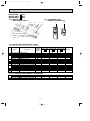
Revision A:
● MCFZ-A18WV- E1 and MCFZ-A24WV- E1
have been added.
FLOOR AND CEILING TYPE AIR CONDITIONERS
Please void OB344.
No. OB344
REVISED EDITION-A
SERVICE MANUAL
Wireless type
Models
MCFZ-A12WV MCFZ-A18WV MCFZ-A24WV -
E1
(WH)
E1
(WH)
E1
(WH)
CONTENTS
(When installed on the floor)
Indication of
model name
MCFZ-A12WV MCFZ-A18WV MCFZ-A24WV -
E1
E1
E1
(When installed on the ceiling)
NOTE:
• This service manual describes technical data of indoor units.
• As for outdoor units MUZ-A12YV - E1 and MUZ-A12YVH - E1 ,
refer to the service manual OB328 REVISED EDITION-A.
• As for outdoor units MUZ-A18YV - E1 and MUZ-A24YV - E1 ,
refer to the service manual OB346 REVISED EDITION-A.
1. PART NAMES AND FUNCTIONS······················2
2. SPECIFICATION·················································4
3. NOISE CRITERIA CURVES ·······························5
4. OUTLINES AND DIMENSIONS ·························6
5. WIRING DIAGRAM ············································6
6. REFRIGERANT SYSTEM DIAGRAM ················8
7. SERVICE FUNCTIONS ······································8
8. TROUBLESHOOTING······································10
9. DISASSEMBLY INSTRUCTIONS ····················19
10. PARTS LIST······················································21
11. OPTIONAL PARTS ···········································23
OB344A--1.qxp
1
04.6.14 1:04 PM
Page 2
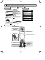
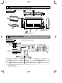
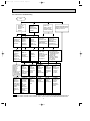
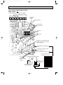
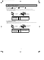
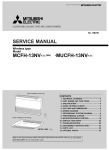
PART NAMES AND FUNCTIONS
MCFZ-A12WV INDOOR UNIT
E1
MCFZ-A18WV -
(When installed on the floor)
E1
MCFZ-A24WV - E1
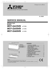
ACCESSORIES
Vertical vanes
Item
Horizontal vane
Installation plate
Unit fixing screw
5 o 12mm
Wireless remote
controller
Remote controller
holder
Fixing screw for
3.5 o 16mm (Black)
Battery (AAA) for
remote controller
Drain hose
Drain pipe cover
Knockout cover
Screw for
4 o 10mm
Operation indicator lamp
Remote control receiving section
Front panel
Air cleaning filter
(White bellows type)(option)
Air inlet
Air filter
Deodorizing filter
(Gray sponge type)(option)
Operation section
(When the air inlet grille is opened.)
Remote controller
(When installed on the ceiling)
Q'ty
2
2
1
1
2
2
1
1
1
2
Emergency
operation switch
MCFZ-A12WV -
E1
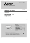
REMOTE CONTROLLER
Signal transmitting section
Operation display section
PM
AM
OPERATE/ STOP
(ON/ OFF) button
TOO
ON/OFF WARM
TOO
COOL
TEMPERATURE buttons
Open the front lid.
Indication of remote controller model
is on back.
˚C
CLOCK
AMPM
AM
ON/OFF
TOO
WARM
TOO
COOL
FAN SPEED CONTROL button
VANE CONTROL button
FAN
STOP
VANE
START
OFF-TIMER button
I FEEL
HEAT
DRY
AUTO
COOL
MODE
HR.
OPERATION SELECT button
ECONO COOL
ECONO COOL button
RESET button
MIN.
RESET CLOCK
2
ON-TIMER button
HR. button
MIN. button
(TIME SET button)
CLOCK SET button
OB344A--1.qxp
04.6.14 1:04 PM
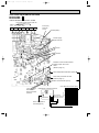
MCFZ-A18WV -
Page 3
E1
MCFZ-A24WV -
E1
REMOTE CONTROLLER
Signal transmitting section
Operation display section
OPERATE/ STOP
(ON/ OFF)button
PM
AM
TOO
ON/OFF WARM
TOO
COOL
TEMPERATURE buttons
Open the front lid.
Indication of remote controller model
is on back.
CLOCK
PM
AM
TOO
ON/OFF WARM
VANE CONTROL button
FAN
TOO
COOL
STOP
I FEEL COOL
VANE
START
HEAT DRY
MODE
HR.
OPERATION SELECT button
ECONO COOL
FAN SPEED CONTROL button
OFF-TIMER button
MIN.
ECONO COOL button
RESET CLOCK
RESET button
3
ON-TIMER button
HR. button
MIN. button
(TIME SET button)
CLOCK SET button
OB344A--1.qxp
2
04.6.14 1:04 PM
Page 4
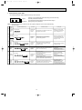
SPECIFICATION
Indoor model
Function
Power supply
Special
remarks
Fan
motor
Electrical
data
Capacity Air flow(High/Med.W/LowW)
Power outlet
Running current ✽1
Power input ✽1
Auxiliary heater
Power factor ✽1
Fan motor current ✽1
Model
Winding
resistance(at 20:)
Dimensions WOHOD
Weight
Air direction
Sound level(High/Med.W/LowW)
Fan speed(High/Med.W/LowW)
Fan speed regulator
Thermistor RT11(at 25:)
Thermistor RT12(at 25:)
Remote controller model
MCFZ-A12WV - E1
MCFZ-A24WV - E1
MCFZ-A18WV - E1
Cooling
Heating
Cooling
Heating
Cooling
Heating
Single phase
Single phase
Single phase
230V, 50Hz
230V, 50Hz
230V, 50Hz
K /h
780/636W/492W
840/744W/642W
840/696W/570W
A
10
10
10
A
0.30
0.36
0.36
W
66
80
80
A(kW)
—
—
—
—
—
—
%
96
97
97
A
0.30
0.36
0.36
RB4V25-AC
RB4V36-DB
RB4V36-AC
WHT-BLK 182.2 BLK-YLW 68.9 WHT-BLK 82.9 BLK-YLW 65.6 WHT-BLK 84.0 BLK-YLW 46.2
"
YLW-BLU 47.5 BLU-BRN 31.5 YLW-BLU 36.0 BLU-BRN 27.0 YLW-BLU 37.2 BLU-BRN 45.2
BRN-RED 22.9
BRN-RED 13.6
BRN-RED 13.7
mm
1,100 O 650 O 180
1,100 O 650 O 180
1,100 O 650 O 180
kg
25
25
25
5
5
5
46/41W/35W
48/45W/42W
48/44W/39W
dB
rpm
1,240/1,060W/845W
1,320/1,190/1,060
1,320/1,145/960
3
3
3
10
10
10
k"
10
10
10
k"
KG04B
KG04C
KG04C
NOTE: Test conditions are based on ISO 5151
Cooling : Indoor Dry-bulb temperature 27°C Wet-bulb
Outdoor Dry-bulb temperature 35°C Wet-bulb
Heating : Indoor Dry-bulb temperature 20°C Wet-bulb
Outdoor Dry-bulb temperature 7°C Wet-bulb
Indoor-Outdoor piping length (one way) : 5 m
w Reference value
✽1 Measured under rated operating frequency.
temperature 19°C
temperature (24°C)
temperature 15°C
temperature 6°C
Specifications and rating conditions of main electric parts
INDOOR UNIT
Model
Item
MCFZ-A12WV -
E1
MCFZ-A18WV -
Indoor fan capacitor
(C11)
Fuse
(F11)
250V 3.15A
Vane motor
(MV)
MP20 12V 250"
Solid state relay
1.8+ 440V
(NR11)
Varistor
ERZV10D471/ TNR10V471K410
(SR141~SR143)
Terminal block
AQG12212/ G3MC-201PL
(TB1/TB2)
Relay
Compressor contactor
3P/ 4P
(X144)
(52C)
MCFZ-A24WV -
E1
G5NB-1A-DC12V/ G5N-1A-DC12V
ALF1T12
–
145 i 2:
Indoor fan motor thermal fuse
4
E1
OB344A--1.qxp
04.6.14 1:04 PM
3
Page 5
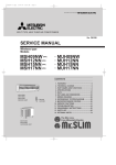
NOISE CRITERIA CURVES
MCFZ-A12WV -
MCFZ-A18WV -
E1
SPEED
SPL(dB(A))
High
46
LINE
OCTAVE BAND SOUND PRESSURE LEVEL, dB re 0.0002 MICRO BAR
OCTAVE BAND SOUND PRESSURE LEVEL, dB re 0.0002 MICRO BAR
80
70
NC-70
60
NC-60
50
NC-50
40
NC-40
30
NC-30
10
APPROXIMATE
THRESHOLD OF
HEARING FOR
CONTINUOUS
NOISE
63
NC-20
125
250
500
1000
2000
4000
8000
SPL(dB(A))
High
48
LINE
80
70
NC-70
60
NC-60
50
NC-50
40
NC-40
30
NC-30
20
10
APPROXIMATE
THRESHOLD OF
HEARING FOR
CONTINUOUS
NOISE
63
NC-20
125
250
500
1000
2000
4000
BAND CENTER FREQUENCIES, Hz
BAND CENTER FREQUENCIES, Hz
MCFZ-A24WV -
SPEED
Test conditions,
Cooling : Dry-bulb temperature 27: Wet-bulb temperature 19:\ Heating : Dry-bulb temperature 20: Wet-bulb temperature 15:
90
Test conditions,
Cooling : Dry-bulb temperature 27: Wet-bulb temperature 19:
Heating : Dry-bulb temperature 20: Wet-bulb temperature 15:
90
20
E1
E1
SPEED
SPL(dB(A))
High
48
LINE
OCTAVE BAND SOUND PRESSURE LEVEL, dB re 0.0002 MICRO BAR
Test conditions,
Cooling : Dry-bulb temperature 27: Wet-bulb temperature 19:\ Heating : Dry-bulb temperature 20: Wet-bulb temperature 15:
90
80
70
NC-70
INDOOR UNIT
60
NC-60
MICROPHONE
50
WALL
NC-50
1m
40
NC-40
30
NC-30
20
10
APPROXIMATE
THRESHOLD OF
HEARING FOR
CONTINUOUS
NOISE
63
125
NC-20
250
500
1000
2000
4000
8000
BAND CENTER FREQUENCIES, Hz
5
1m
8000
OB344A--1.qxp
4
04.6.14 1:04 PM
Page 6
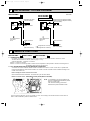
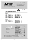
OUTLINES AND DIMENSIONS
MCFZ-A12WV -
E1
MCFZ-A18WV -
E1
MCFZ-A24WV -
Unit: mm
E1
114
INDOOR UNIT
80.8
(When installed on the floor)
500
mm
16
112.8
616.5
500mm or more
650
500mm or more
906
93
77
(When installed on the ceiling)
or m
143
500mm or more
113
42.5
1000mm or more
170
ore
180
1100
58
Gas line
9.52(MCFZ-A12WV)
12.7(MCFZ-A18WV)
15.88(MCFZ-A24WV)
19
162
Liquid line
6.35
Wireless remote controller
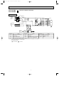
WIRING DIAGRAM
MCFZ-A12WV INDOOR UNIT
E1
MODEL WIRING DIAGRAM
TB1
PE
POWER
SUPPLY
~/N 230V
50Hz
GRN/YLW
L
BRN
N
BLU
1
2
3
CIRCUIT BREAKER
4
52C
3
CN201
230V~
TO OUTDOOR
UNIT
CONNECTING
3
F11
CN CN
101 113
4
5
NAME
INDOOR FAN CAPACITOR
F11
FUSE (3.15A)
HIC1
MF
LDFM
LDFL
SR142
LDFVL
DISP/
RECEIVER
P.C.BOARD
ELECTRONIC CONTROL P.C BOARD
RT12
WHT
ORN
RED
BLK
YLW
BLU
BRN
1
2
3
4
5
6
7
8
WHT
ORN
RED
BLK
YLW
BLU
BRN
MF
5
MV
SW/THERMO
P.C.BOARD
RT11
NAME
SYMBOL
MV
2
GRN/YLW
6
5
C11
LDCOM
LDC11
LDC12
LDFH
SR141
CN
151
RED
GRN/YLW
SYMBOL
2
SR143
BLU
REMOTE
CONTROLLER
C11
X144
2 TB2 WHT
N
12V
CN
112
HIC1
NR11
5
VANE MOTOR
NAME
SYMBOL
SR141~SR143 SOLID STATE RELAY
NR11
VARISTOR
DC/DC CONVERTER
RT11
ROOM TEMPERATURE THERMISTOR
X144
RELAY
INDOOR FAN MOTOR(INNER FUSE)
RT12
INDOOR COIL THERMISTOR
52C
COMPRESSOR CONTACTOR
NOTES: 1.About the outdoor side electric wiring refer to the outdoor unit electric wiring diagram for servicing.
2.Use copper conductors only. (For field wiring)
3.Symbols below indicate.
: Terminal block
: Connector
6
TB1, TB2
TERMINAL BLOCK
OB344A--1.qxp
04.6.14 1:04 PM
MCFZ-A18WV MCFZ-A24WV -
Page 7
MODELS WIRING DIAGRAM
E1
E1
INDOOR UNIT
TB1
PE
GRN/YLW
N
BLU
L
N
TB2
TAB12
BLU
F11
CN CN
101 113
3
CN
151
4
5
REMOTE
CONTROLLER
NAME
DISP/
RECEIVER
P.C.BOARD
1
2
3
4
5
6
7
8
WHT
ORN
RED
BLK
YLW
BLU
BRN
RT11
NAME
SYMBOL
VANE MOTOR
NR11
VARISTOR
DC/DC CONVERTER
RT11
ROOM TEMPERATURE THERMISTOR
INDOOR FAN MOTOR(INNER FUSE)
RT12
INDOOR COIL THERMISTOR
NOTES: 1.About the outdoor side electric wiring refer to the outdoor unit electric wiring diagram for servicing.
2.Use copper conductors only. (For field wiring)
3.Symbols below indicate.
: Connector
7
NAME
SYMBOL
SR141~SR143 SOLID STATE RELAY
TB1, TB2
X144
TERMINAL BLOCK
RELAY
MF
GRN/YLW
SW/THERMO
P.C.BOARD
FUSE (3.15A)
: Terminal block
WHT
ORN
RED
BLK
YLW
BLU
BRN
RT12
MV
F11
MF
2
5
INDOOR FAN CAPACITOR
HIC1
LDCOM
LDC11
C11 LDC12
LDFH
X144
LDFM
SR143
LDFL
SR142
LDFVL
SR141
ELECTRONIC CONTROL P.C BOARD
C11
MV
2
6
5
SYMBOL
CN
112
HIC1
BRN
CIRCUIT BREAKER
TO OUTDOOR
UNIT
CONNECTING
12V
1
2
3
CN201
RED
NR11
POWER
SUPPLY
~/N 230V
50Hz
OB344A--1.qxp
6
04.6.14 1:04 PM
Page 8
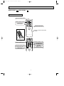
REFRIGERANT SYSTEM DIAGRAM
MCFZ-A12WV-
MCFZ-A18WV- E1
MCFZ-A24WV- E1
INDOOR UNIT
E1
INDOOR UNIT
Refrigerant pipe [9.52
(with heat insulator)
Muffler
Indoor
heat
exchanger
Indoor coil
thermistor
Flared connection
RT12
Indoor
heat
Distributor
exchanger
Unit : mm
Refrigerant pipe [12.7(MCFZ-A18MV)
Refrigerant pipe [15.88(MCFZ-A24MV)
(with heat insulator)
Flared connection
Indoor coil
thermistor
RT12
Room temperature
thermistor
RT11
Flared connection
Refrigerant pipe
[6.35
(with heat insulator)
7
Room temperature
thermistor
RT11
Flared connection
Refrigerant flow in cooling
Refrigerant flow in heating
Refrigerant pipe
[6.35
(with heat insulator)
SERVICE FUNCTIONS
MCFZ-A12WV -
E1
MCFZ-A18WV -
E1
MCFZ-A24WV -
E1
7-1. TIMER SHORT MODE
For service, set time can be shortened by short circuit of JPG and JPS on the electronic control P.C. board.
The time will be shortened as follows. (Refer to page 17 or 18.)
3-minutes time delay : 3-minutes → 3-seconds
Set time : 1 minute ➔ 1-second
Set time : 3 minute ➔ 3-second (It takes 3 minutes for the compressor to start operation. However, the starting time is
shortened by short circuit of JPG and JPS.)
7-2. P.C. BOARD MODIFICATION FOR INDIVIDUAL OPERATION
A maximum of 4 indoor units with wireless remote controllers can be used in a room. In this case, to operate each
indoor unit individually by each remote controller, P.C. boards of remote controller must be modified according to the
number of the indoor unit.
How to modify the remote controller P.C. board
Remove batteries before modification. The board has a print as shown below;
Remote controller model : KG04B(MCFZ-A12WV),KG04C(MCFZ-A18/A24WV)
J2
NOTE : For remodelling, take out the batteries and
press the OPERATE/STOP(ON/OFF) button
twice or 3 times at first.
After finish remodelling, put back the
batteries then press the RESET button.
J1
The P.C. board has the print “J1” and “J2”. Solder “J1” and “J2” according to the number of indoor unit as shown in
Table 1. After modification, press the RESET button.
8
OB344A--1.qxp
04.6.14 1:04 PM
Page 9
Table1.
1 unit operation
2 units operation
3 units operation
4 units operation
No. 1 unit
No modification
Same as at left
Same as at left
Same as at left
No. 2 unit
–
Solder J1
Same as at left
Same as at left
No. 3 unit
–
–
Solder J2
Same as at left
No. 4 unit
–
–
–
Solder both J1 and J2
How to set the remote controller exclusively for particular indoor unit
After you turn the breaker ON, the first remote controller that sends the signal to the indoor unit will be regarded as the
remote controller for the indoor unit.
The indoor unit will only accepts the signal from the remote controller that has been assigned to the indoor unit once they
are set.
The setting will be cancelled if the breaker has turned off, or the power supply has shut down.
Please conduct the above setting once again after the power has restored.
7-3. AUTO RESTART FUNCTION
When the indoor unit is controlled with the remote controller, the operation mode, the set temperature, and the fan speed
are memorized by the indoor electronic control P.C. board. The “AUTO RESTART FUNCTION” sets to work the moment
power has restored after power failure.Then, the unit will restart automatically. However if the unit is operated in “I FEEL
CONTROL” or “AUTO” mode before power failure, the operation is not memorized. In “I FEEL CONTROL” mode, the operation is decided by the initial room temperature.
How to release “AUTO RESTART FUNCTION”
1Turn off the main power for the unit.
2Pull out the electronic control P.C. board. (Refer to page 19.)
3Solder jumper wire to the JR07 on the indoor electronic
CN201
C11
control P.C. board. (Refer to page 17 or 18.)
CN105
SW2
CN112
CN101
IC101
CN102
SW1
CN113 CN151
52C
JR07
Operation
1If the main power has been cut, the operation settings remain.
2After the power is restored, the unit restarts automatically according to the memory.(However, it takes at least 3 minutes
for the compressor to start running.)
NOTE
•The operation settings are memorized when 10 seconds have passed after the indoor unit was operated with the
remote controller.
•If main power is turned OFF or a power failure occurs while AUTO START/STOP timer is active, the timer setting is
cancelled.
•If the unit has been off with the remote controller before power failure, the auto restart function does not work as the
power button of the remote controller is off.
•To prevent breaker off due to the rush of starting current, systematize other home appliances not to turn on at the same
time.
•When some air conditioners are connected to the same supply system, if they are operated before power failure, the
starting current of all the compressors may flow simultaneously at restart.
Therefore, the special counter-measures are required to prevent the main voltage-drop or the rush of the starting current
by adding to the system that allows the units to start one by one.
9
OB344A--1.qxp
8
04.6.14 1:04 PM
Page 10
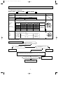
TROUBLESHOOTING
MCFZ-A12WV -
E1
MCFZ-A18WV -
E1
MCFZ-A24WV -
E1
8-1. Cautions on troubleshooting
1. Before troubleshooting, check the following:
(1) Check the power supply voltage.
(2) Check the indoor/outdoor connecting wire for mis-wiring.
2. Take care the following during service.
(1) Before servicing the air conditioner, be sure to first turn off the remote controller to stop the main unit, and then after
confirming the horizontal vane has completely closed, turn off the breaker.
(2) Be sure to unplug the power cord before removing the air inlet grille, the front panel, the cabinet, the top panel and
the electronic control P.C. boards.
(3) When removing the electronic control P.C. board, hold the edge of the board with care NOT to apply stress on the
components.
(4) When connecting or disconnecting the connectors, hold the housing of the connector. DO NOT pull the lead wires.
3. Troubleshooting procedure
(1) First, check if the OPERATION INDICATOR lamp on the indoor unit is flashing on and off to indicate an abnormality.
To make sure, check how many times the abnormality indication is flashing on and off before starting service work.
(2) If the electronic control P.C. board is supposed to be defective, check the copper foil pattern for disconnection and
the components for bursting and discoloration.
(3) When troubleshooting, refer to the flow chart and the check table on page 11 and 12.
4. How to replace batteries
Weak batteries may cause the remote controller malfunction.
In this case, replace the batteries to operate the remote controller normally.
1 Remove the front lid and insert batteries.
2 Press the RESET button with tip end of ball point
Then reattach the front lid.
pen or the like, and then use the remote controller.
Insert the negative pole
of the batteries first.
Check if the polarity of
the batteries are correct.
RESET button
NOTE : 1.These figures show about MCFZ-A18WV or MCFZ-A24WV.
2. If the RESET button is not pressed, the remote controller may not operate correctly.
3. Remote controller of MCFZ-A12WV has a circuit to automatically reset the microcomputer when batteries are
replaced.
This function is equipped to prevent the microcomputer from malfunctioning due to the voltage drop caused by
the battery replacement.
10
OB344A--1.qxp
04.6.14 1:04 PM
Page 11
8-2. Instruction of troubleshooting
Start
Indoor unit
operates.
Outdoor unit
doesn't
operate.
Outdoor unit
operates in
only Test Run
operation.
Check room
temperature
thermistor.
Refer to
"Test point
diagram and
voltage" on
page 17 or 18.
Flash on and
off at 0.5second
intervals
Cause:
Indoor/
Outdoor unit
• Mis-wiring
or trouble of
serial signal
Refer to D
"How to
check miswiring and
serial signal
error (When
outdoor unit
doesn't
work)" on
page 15 or
16.
Outdoor unit
doesn't
operate
even in
Test Run
operation.
Refer to
"Check of
inverter/
compressor".
Indoor unit
operates.
Outdoor unit
doesn't operate
normally.
Unit doesn't
operate
normal
operation in
COOL or
HEAT mode.
Refer to
"Check of
R.V. coil".
Indoor unit
doesn't receive
the signal from
remote controller.
Indoor unit
operates, when
the EMERGENCY
OPERATION
switch is pressed.
Refer to B
"Check of
remote controller
and receiver
P.C. board"
on page 14.
OPERATION INDICATOR
lamp on the indoor unit is
flashing on and off.
Indoor unit
doesn't operate,
when the
EMERGENCY
OPERATION
switch is pressed.
1. Check indoor / outdoor
connecting wire.
(Check if the power
is supplied to the
indoor unit.)
2. Refer to C
"Check of indoor
electronic control
P.C. board"
on page 14.
2-time flash
Cause:
Indoor unit
• Trouble of
room
temperature/
indoor coil
thermistor
4-time flash
Cause:
Indoor unit
• Trouble of
indoor unit
control
system
5-time flash
Cause:
Outdoor unit
• Outdoor
power
system
abnormality
6-time flash
Cause:
Outdoor unit
• Trouble of
thermistor
in outdoor
unit
7-time flash
Cause:
Outdoor unit
• Trouble of
outdoor
control
system
Check room
temperature
thermistor
and indoor
coil
thermistor.
Refer to
"Test point
diagram and
voltage"
on page 17
or 18.
Replace the
indoor
electronic
control P.C.
board.
Refer to
"Check of
inverter/
compressor".
Refer to
"Check of
outdoor
thermistors".
Check the
inverter P.C.
board or
outdoor
electronic
control P.C.
board.
As for outdoor units MUZ-A12YV and MUZ-A12YVH, refer to service manual OB328 REVISED EDITION-A.
As for outdoor units MUZ-A18YV and MUZ-A24YV, refer to service manual OB346 REVISED EDITION-A.
11
OB344A--1.qxp
04.6.14 1:04 PM
Page 12
1. Troubleshooting check table
• The following indication applies regardless of shape of the indicator.
· Flashing of the OPERATION INDICATOR lamp (left-hand side lamp)
indicates possible abnormalities.
· The OPERATION INDICATOR lamp (left-hand side lamp) is
Not lighted lighting during normal operation.
Operation Indicator
Lighted
NOTE : Before taking measures, make sure that the symptom reappears for accurate troubleshooting.
Self check table
No.
Abnormal
point
1
Mis-Wiring
or Serial
signal
Operation indicator lamp
Symptom
Detection method
0.5-second ON
Outdoor unit
does not
operate.
3 minutes after power supply turns ON, when
serial signal is not received.
Check point
• Refer to D "How to check
mis-wiring and serial signal
error." on page 15 or 16.
0.5-second OFF
Indoor coil
thermistor
2
Room
temperature
thermistor
Indoor
3 control
system
2-time flash
Outdoor unit
does not
operate.
Detect Indoor coil/room temperature
thermistor short or open circuit every 8
seconds during operation.
• Refer to the characteristics of
indoor coil thermistor, and
room temperature thermistor
on page 17 or 18.
Outdoor unit
does not
operate.
When it cannot properly read data in the
nonvolatile memory of indoor electronic
control P.C. board.
• Replace the indoor electronic
control P.C. board.
Outdoor unit
does not
operate.
When it consecutively occurs 3 times that
compressor stops for overcurrent protection
within 1 minute after start-up.
• Refer to "Check of inverter/
compressor".
Refer to service manual
OB328 REVISED EDITION-A
or OB346 REVISED EDITION-A.
Outdoor unit
does not
operate.
<Thermistor short>
Thermistors are abnormal when they short
after compressor start-up.
<Thermistor open>
Thermistors are abnormal when they open
after compressor start-up.
However, discharge temperature thermistor is
abnormal when open circuit is detected more
than 10 minutes after compressor start-up.
Outdoor unit
does not
operate.
When it cannot properly read data in the
nonvolatile memory of inverter P.C. board or
outdoor electronic control P.C. board.
2.5-second OFF
4-time flash
2.5-second OFF
5-time flash
4
Outdoor
power
system
2.5-second OFF
6-time flash
5
Outdoor
thermistor
2.5-second OFF
6
Outdoor
control
system
7-time flash
2.5-second OFF
12
• Shortage of refrigerant.
Refer to "Check of outdoor
thermistor".
Refer to service manual
OB328 REVISED EDITION-A
or OB346 REVISED EDITION-A.
• Check the inverter P.C.
board or outdoor electronic
control P.C. board.
Refer to service manual
OB328 REVISED EDITION-A
or OB346 REVISED EDITION-A.
OB344A--1.qxp
04.6.14 1:04 PM
Page 13
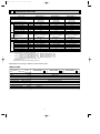
2. Trouble criterion of main parts
MCFZ-A12WV -
E1
MCFZ-A18WV -
Part name
Room
temperature
thermistor (RT11)
E1
MCFZ-A24WV -
E1
Figure
Check method and criterion
Measure the resistance with a tester.
(Part temperature 10°C ~ 30°C)
Indoor coil
thermistor (RT12)
Normal
Abnormal
8kΩ ~ 20kΩ
Open or short-circuit
Measure the resistance between the terminals with a tester.
(Part temperature 10°C ~ 30°C)
Indoor fan
motor
(MF)
Color of lead
wire
MCFZ-A12WV
MCFZ-A18WV
MCFZ-A24WV
WHT-BLK
175~190Ω
79~87Ω
80~88Ω
BLK-YLW
66~72Ω
63~69Ω
44~49Ω
YLW-BLU
45~50Ω
34~38Ω
35~39Ω
BLU-BRN
30~33Ω
25~29Ω
43~47Ω
BRN-RED
22~24Ω
13~15Ω
13~15Ω
INNER FUSE
145 i 2: CUT OFF
Normal
Abnormal
GRN
YLW
Open or
short-circuit
Measure the resistance between the terminals with a tester.
(Part temperature 10°C ~ 30°C)
Vane
motor
(MV)
Color of lead
wire
Normal
BRN-other
one
328 ~ 356Ω
FUSE
BLK YLW BLU BRN RED ORN
WHT
RED
ROTOR
Abnormal
YLW
BRN
Open or
short-circuit
ORN
GRN
Indoor fan does not operate.
A Check of indoor fan motor
No
Turn OFF power supply.
Check connector (Fan motor) visually.
Yes
Is soldered point of the connector
correctly soldered?
Are lead wires connected?
No
Yes
Reconnect the lead wires.
Resolder it.
Disconnect lead wires from connector (Indoor fan motor).
Measure resistance between lead wires No.1 and No.4 and then No.3 and No.4 of the indoor fan
motor.
Is resistance 0 (short circuit) or ∞ (open circuit)?
Yes ( 0 or ∞ )
Replace the indoor fan motor.
13
No
(others)
Replace the indoor electronic control
P.C. board.
OB344A--1.qxp
04.6.14 1:04 PM
Page 14
Indoor unit operates by pressing the EMERGENCY OPERATION switch, but does not operate with the remote controller.
B Check of remote controller and receiver P.C. board
w Check if the remote controller is exclusive for this air conditioner.
Switch on the remote controller.
Is LCD display on remote
controller visible?
No
Replace the batteries.(Refer to page 10.)
(not clear)
Yes
Remove the batteries, then set them back and
press the RESET button. (Refer to 10.) Check
if the unit operates with the remote controller.
Does the unit operate with remote
controller?
No
Turn on a radio to AM and press switch
on remote controller.
Yes
OK
No
Replace the remote controller.
Is noise heard from radio?
Yes
Are there any fluorescent lights of
inverter or rapid-start type within
the range of 1m?
Yes
● Reinstall the unit away from lights.
● Attach a filter on receiving section of
the indoor unit.
No
Measure the voltage between receiver P.C.board connector CN101 No.2(+) and No.1 (-)
when remote controller button is pressed.
Yes
Is the voltage approx. 4V DC ?
Replace the indoor electronic control
P.C. board.
No(5V or 0V DC)
Replace the receiver P.C. board.
The unit does not operate with the remote controller.
Also, the OPERATION INDICATOR lamp doesn’t light up by pressing the EMERGENCY OPERATION switch.
C Check of indoor electronic control P.C. board
Replace the fuse.
Yes
Check both “parts side” and “pattern side” of indoor
electronic control P.C. board visually.
Is fuse (F11) blown?
No
Is varistor (NR11) burnt?
Yes
Replace the varistor.
14
No
Replace the indoor
electronic control
P.C. board.
OB344A--1.qxp
04.6.14 1:04 PM
Page 15
When OPERATION INDICATOR lamp flashes ON and OFF in every 0.5-second.
Outdoor unit does not operate.
D How to check mis-wiring and serial signal error (when outdoor unit does not work)
MCFZ-A12WV
Start
• Turn ON the power supply(Indoor unit).
• Press once EMERGENCY OPERATION switch.
w Short circuit of JPG and JPS on the indoor
electronic control P.C. board enables
self-check to be displayed in 3 seconds.
After 3 minutes, mis-wiring is indicated
(0.5-second ON, 0.5-second OFF)
on OPERATION INDICATOR
lamp on indoor unit.w
Yes
Make them sure.
Is there any mis-wiring, poor contact,
or wire disconnection? w2
No
A
B
:
CLOCK
AMPM
12345
AMPM
•The following indication
applies regardless of shape
of the indicator.
Turn OFF the power supply(Indoor unit).
Disconnect the indoor/ outdoor connecting wire.
Short-circuit indoor terminal block N and 3.
Turn ON the power supply(Indoor unit).
During pressing both the OPERATION SELECT button
and TOO COOL button on the remote controller at the
same time, press the RESET button.
At first, release the RESET button.
And release the other two buttons since all LCD in
operation display section of the remote controller is
displayed after 3 seconds.
Transmit the signal of remote controller, pressing
OPERATE/STOP (ON/OFF) button on the remote
controller.
(The above procedure allows OPERATION INDICATOR
lamp to indicate the failure-mode.)
w2 Mis-wiring may damage indoor electronic
control P.C. board during the operation.
Be sure to confirm the wiring is correct
before the operation starts.
Blinking
Does the right side of OPERATION INDICATOR
lamp blink quickly?
Operation Indicator
No
(light up or OFF)
Replace the indoor
electronic control
P.C. board.
Yes
Release the failure mode. w3
Remove the short-circuit between indoor terminal block N
and 3.
Reconnect the indoor/ outdoor connecting wire.
Turn ON the power supply(Indoor unit).
Press the EMERGENCY OPERATION switch.
Is there amplitude of 5 to 10V DC between outdoor
terminal block N and 3 after 3 minutes (for confirmation of
serial signal)?
Yes
Is there 230V AC between outdoor terminal
block 2 and N?
Yes
1. Turn OFF the power supply.
2. Disconnect the connector (CN61) between the
compressor and the power transistor module.
3. Turn ON the power supply.
4. Press the EMERGENCY OPERATION switch.
w4 Replace the inverter P.C.
board.
Yes
Yes
Is there voltage approximate 280V DC between
LD61A (+) and LD66A (–) on the inverter P.C.
board arter 3 minutes?
No
Turn OFF the power supply and then turn ON
again.
Press EMERGENCY OPERATION switch.
After 3 minutes, is there approximate 230V AC
between outdoor terminal block 2 and N?
No
Replace the indoor/ outdoor connecting wire.
w4 Be careful to the residual voltage of smoothing capacitor.
As for outdoor units MUZ-A12YV and MUZ-A12YVH,
refer to service manual OB328 REVISED EDITION-A.
No
Replace the
indoor/ outdoor
connecting wire.
No
Replace the
indoor/ outdoor
connecting wire.
w3 Be sure to release the failure-mode
recall function after checking.
Procedure of release of failure-mode.
1 Press the EMERGENCY
OPERATION switch.
2 Turn OFF the power supply.
3 Press the RESET button on the
remote controller.
A
· Turn OFF inverter-controlled lighting
equipment.
· Turn OFF the power supply and then
turn ON again(Indoor unit).
· Press the EMERGENCY
OPERATION switch.
Is mis-wiring
indicated when
the contactor
(52C) on the
indoor electronic
control P.C.
board turns ON
3 minutes later?
Yes
B
15
No
· Reinstall
either the
unit or the
light each
other away.
· Attach a filter
on receiving
section of
the indoor
unit.
OB344A--1.qxp
04.6.14 1:04 PM
Page 16
MCFZ-A18WV
MCFZ-A24WV
Start
• Turn ON the power supply (Indoor/ outdoor unit).
• Press once EMERGENCY OPERATION switch.
After 3 minutes, mis-wiring is indicated
(0.5-second ON, 0.5-second OFF)
on OPERATION INDICATOR
lamp on the indoor unit.w
Yes
Make them sure.
w Short circuit of JPG and JPS on the indoor
electronic control P.C. board enables
self-check to be displayed in 3 seconds.
Is there any mis-wiring, poor contact,
or wire disconnection? w2
No
A
B
:
CLOCK
AMPM
12345
AMPM
•The following indication
applies regardless of shape
of the indicator.
Turn OFF the power supply (Indoor/ outdoor unit).
Disconnect the indoor/ outdoor connecting wire.
Short-circuit indoor terminal block N and 3.
Turn ON the power supply (Indoor/ outdoor unit).
During pressing both the OPERATION SELECT button
and TOO COOL button on the remote controller at the
same time, press the RESET button.
At first, release the RESET button.
And release the other two buttons since all LCD in
operation display section of the remote controller is
displayed after 3 seconds.
Transmit the signal of remote controller, pressing
OPERATE/STOP (ON/OFF) button on the remote
controller.
(The above procedure allows OPERATION INDICATOR
lamp to indicate the failure-mode.)
w2 Mis-wiring may damage indoor electronic
control P.C. board during the operation.
Be sure to confirm the wiring is correct
before the operation starts.
Blinking
Does the right side of OPERATION INDICATOR
lamp blink quickly?
Operation Indicator
No
(light up or OFF)
Replace the indoor
electronic control
P.C. board.
Yes
Release the failure mode. w3
Remove the short-circuit between indoor terminal block N
and 3.
Reconnect the indoor/ outdoor connecting wire.
Turn ON the power supply (Indoor/ outdoor unit).
Press the EMERGENCY OPERATION switch.
Is there amplitude of 5 to 10V DC between outdoor
terminal block N and 3 after 3 minutes (for confirmation of
serial signal)?
Yes
Reconnect the
power supply
cable.
No
Is there 230V AC between outdoor terminal
block L and N?
Yes
Check of power
supply.
No
Is there 325V DC between CN801 1 and 3 on the
outdoor electronic control P.C. board?
Yes
Replace the outdoor
electronic control P.C.
board.
As for outdoor units MUZ-A18YV and MUZ-A24YV,
refer to service manual OB346 REVISED EDITION-A.
No
Replace the
indoor/ outdoor
connecting wire.
w3 Be sure to release the failure-mode
recall function after checking.
Procedure of release of failure-mode.
1 Press the EMERGENCY
OPERATION switch.
2 Turn OFF the power supply
(Indoor/ outdoor unit).
3 Press the RESET button on the
remote controller.
A
· Turn OFF inverter-controlled lighting
equipment.
· Turn OFF the power supply and then
turn ON again (Indoor/ outdoor unit).
· Press the EMERGENCY
OPERATION switch.
After 3 minutes,
is mis-wiring
indicated on
OPERATION
INDICATOR
lamp on the
indoor unit?
Yes
B
16
· Reinstall
either the
unit or the
light each
No
other away.
· Attach a filter
on receiving
section of
the indoor
unit.
OB344A--1.qxp
04.6.14 1:04 PM
Page 17
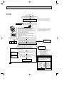
TEST POINT DIAGRAM AND VOLTAGE
MCFZ-A12WV - E1
Indoor electronic control P.C. board
Fan motor power supply 230V AC
7
6
5
4
3
2
1
Fuse (F11)
250V AC
3.15A
Varistor (NR11)
Power supply
input 230V AC
+
–
–
+
} 5V DC
} 12V DC
Release of “Auto restart function”
Solder jumper wire to the JR07.
(Refer to page 9.)
Room temperature thermistor
(RT11)
Time short point JPG and JPS
(Refer to page 8.)
Indoor coil thermistor (RT12)
Indoor coil thermistor (RT12)
Room temperature thermistor (RT11)
40
No.2
No.1
Receiver P.C.
board connector
(CN101)
EMERGENCY OPERATION switch
30
RT11
TH113
CH313
DE00R697B
To the indoor
electronic control
P.C.board CN113
Resistance (K')
High
GILMS
Med.
+
Low
–
Very
Low
20
10
Room temperature
thermistor(RT11)
12
0
17
0
10 20 30 40 50
Temperature ( C)
60
OB344A--1.qxp
04.6.14 1:04 PM
Page 18
TEST POINT DIAGRAM AND VOLTAGE
MCFZ-A18WV - E1
MCFZ-A24WV - E1
Indoor electronic control P.C. board
Fan motor power supply 230V AC
7
6
5
4
3
2
1
Fuse (F11)
250V AC
3.15A
Varistor (NR11)
Power supply
input 230V AC
+
–
–
+
} 5V DC
} 12V DC
Release of “Auto restart function”
Solder jumper wire to the
JR07.
(Refer to page 9.)
Room temperature thermistor (RT11)
Time short point JPG and JPS
(Refer to page 8.)
Indoor coil thermistor (RT12)
Indoor coil thermistor (RT12)
Room temperature thermistor (RT11)
40
No.2
No.1
Receiver P.C.
board connector
(CN101)
EMERGENCY OPERATION switch
30
RT11
TH113
CH313
DE00R697B
To the indoor
electronic control
P.C.board CN113
Resistance (K')
High
GILMS
Med.
+
Low
–
Very
Low
20
10
Room temperature
thermistor(RT11)
18
12
0
0
10 20 30 40 50
Temperature ( C)
60
OB344A--1.qxp
04.6.14 1:04 PM
9
Page 19
DISASSEMBLY INSTRUCTIONS
<"Terminal with lock mechanism" Detaching points>
In case of terminal with lock mechanism, detach the terminal as shown below.
There are two types ( Refer to (1) and (2)) of the terminal with lock mechanism.
The terminal with no lock mechanism can be removed by pulling it out.
Check the shape of the terminal and work.
Slide the sleeve and check if there is a locking lever or not.
Sleeve
Locking lever
MCFZ-A12WV INDOOR UNIT
E1
1Slide the sleeve.
2Pull the terminal while
pushing the locking
lever.
MCFZ-A18WV -
E1
MCFZ-A24WV -
E1
OPERATING PROCEDURE
PHOTOS
1. Removing the electronic control P.C. board.
(1) Pull out the upper part of the grille. (Photo 1)
(2) Remove the screws of the grille.
(3) Remove screws of terminal block cover.
Remove the terminal block cover and remove the terminal
block.
(4) Remove the screws of the electronic box cover.
(5) Pull out the electronic control P.C. board.
Photo 1
Photo 3
MCFZ-A12WV
Screws
Photo 2
Electronic control P.C. board
MCFZ-A18WV
MCFZ-A24WV
Electronic box
Electronic control P.C. board
19
Terminal block
OB344A--1.qxp
04.6.14 1:04 PM
Page 20
OPERATING PROCEDURE
PHOTOS
2. Removing the indoor fan motor
Photo 4
(1)
(2)
(3)
(4)
(5)
Remove the grille. (Refer to 1(1) (2).)
Remove the fan casing.(upper)
Disconnect the connector of the indoor fan motor.
Disconnect the ground wire of the fan motor.
Remove the screws of the motor band and remove the
catch.
(6) Take out the sirocco fan and the indoor fan motor.
Fan casing
(upper)
Motor band
Indoor fan motor
Screws
3. Removing the indoor heat exchanger.
(1) Remove the grille. (Refer to 1(1) (2).)
(2) Remove the screws on both side and in front of the front
panel. (Photo 5)
(3) Remove the screws of the nozzle assembly. (Photo 6)
(4) Remove the electronic box. (Refer to 1.)
(5) Remove the indoor fan motor. (Refer to 2.)
(6) Remove the screws of the motor support.
(7) Remove the fan casing. (Iower)
(8) Remove the insulation of the drain pan and remove the
screws. (Photo 7)
(9) Remove the screws under the drain pan. (Photo 8)
(10) Remove the drain pan.
(11) Remove the indoor heat exchanger.
Fan
casing(upper)
Photo 5
Screws
Photo 7
Photo 6
Insulation and screws
Photo 8
Screws
Screws
20
OB344A--1.qxp
04.6.14 1:04 PM
10
Page 21
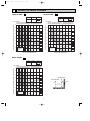
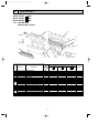
PARTS LIST
MCFZ-A12WV MCFZ-A18WV MCFZ-A24WV -
E1
E1
E1
(WH)
(WH)
(WH)
10-1. INDOOR UNIT
STRUCTURAL PARTS
15
14
13
1
12
11
2
10
3
9
4
8
5
6
7
Part number that is circled is not shown in the illustration.
No.
1
2
3
4
5
6
7
8
9
10
11
12
13
14
15
16
Part No.
E02
E02
E02
E02
E02
E02
E02
E02
E02
E02
E02
E02
E02
E02
E02
E02
E02
E02
E02
227
179
179
179
179
215
179
179
151
179
138
179
138
179
227
823
824
227
179
303
971
100
010
000
700
237
238
666
667
666
972
667
231
235
620
620
040
142
Q'ty/unit
Symbol
MCFZ-A12WV
MCFZ-A18WV
MCFZ-A24WV
in Wiring
Part name
Remarks
E1
E1
- E1
Diagram
(WH)
(WH)
(WH)
1
1
1
MV
VANE MOTOR
1
1
1
INSTALLATION METAL (L)
2
2
2
AIR FILTER
1
1
1
GRILLE (WH)
1
1
1
FRONT PANEL (WH)
1
1
1
DRAIN PAN
2
2
2
FAN CASING (U)
2
2
2
FAN CASING (L)
1
{9.52
UNION (GAS)
1
{12.7
UNION (GAS)
1
{15.88
UNION (GAS)
1
1
1
INSTALLATION METAL (R)
1
1
1
{6.35
UNION (LIQUID)
1
1
1
BACK PANEL (IN)
1
1
1
NOZZLE (WH)
1
INDOOR HEAT EXCHANGER
1
1
INDOOR HEAT EXCHANGER
1
1
1
VANE (WH)
3
3
3
3PCS/SET
GRILLE CATCH (WH)
21
OB344A--1.qxp
04.6.14 1:04 PM
Page 22
MCFZ-A12WV - E1 (WH)
MCFZ-A18WV - E1 (WH)
MCFZ-A24WV - E1 (WH)
10-2. INDOOR UNIT
ELECTRICAL PARTS
9
10-3. ACCESSORY AND
REMOTE CONTROLLER
8
7
6
5
4
12
13
1
2
3
2
1
10-2. INDOOR UNIT ELECTRICAL PARTS
Part numbers that are circled are not shown in the illustration.
No.
1
2
3
4
5
6
7
8
9
10
11
Part No.
E02
E02
E02
E02
E02
E02
E02
E02
E02
E02
E02
E02
E02
E02
E02
E02
179
179
228
229
684
842
826
823
227
327
842
875
876
215
820
127
500
505
300
300
300
375
375
375
468
307
452
452
452
328
385
382
Q'ty/unit
Symbol
MCFZ-A12WV
MCFZ-A18WV
MCFZ-A24WV
in Wiring
Part name
Remarks
- E1
- E1
- E1
Diagram
(WH)
(WH)
(WH)
2
2
2
SIROCCO FAN
2
2
2
2PCS/SET
FAN MOTOR RUBBER MOUNT
MF
1
RB4V25INDOOR FAN MOTOR
MF
1
RB4V36INDOOR FAN MOTOR
MF
1
RB4V36INDOOR FAN MOTOR
TB2
4P
1
TERMINAL BLOCK
TB2
1
1
3P
TERMINAL BLOCK
TB1
1
1
3P
1
TERMINAL BLOCK
DISP/RECEIVER
1
1
1
RECEIVER P.C. BOARD
P.C. BOARD
RT12
1
1
1
INDOOR COIL THERMISTOR
1
ELECTRONIC CONTROL P.C. BOARD
1
ELECTRONIC CONTROL P.C. BOARD
1
ELECTRONIC CONTROL P.C. BOARD
1
1
1
SWITCH & ROOM TEMPERATURE THERMISTOR P.C. BOARD SW/THERMO
P.C. BOARD
NR11
1
1
1
VARISTOR
F11
1
1
1
3.15A
FUSE
10-3. ACCESSORY AND REMOTE CONTROLLER
12
13
E02 842 426 REMOTE CONTROLLER
E02 826 426 REMOTE CONTROLLER
E02 527 083 REMOTE CONTROLLER HOLDER
1
1
22
1
1
1
1
KG04B
KG04C
OB344A--1.qxp
04.6.14 1:04 PM
11
Page 23
OPTIONAL PARTS
MCFZ-A12WV -
E1
MCFZ-A18WV -
E1
MCFZ-A24WV -
E1
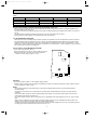
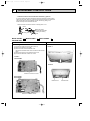
11-1. AIR CLEANING FILTER
● If the air cleaning filter is clogged, it may lower the unit’s capacity or cause condensation at the air outlet.
● The air cleaning filter is disposable. The standard usable term is about 4 months. However, if the color of the filter
turns to dark brown, replace soon.
Remove the air
filter and the
air cleaning filter
together.
Separate the air
cleaning filter
(white bellows type)
from the air filter.
Models
Part No.
MCFZ-A12WV - E1
MCFZ-A18WV - E1
MCFZ-A24WV - E1
MAC - 1200 FT
11-2. DEODORIZING FILTER
● Clean the filter every two weeks. When it becomes too dirt, clean it more often.
● Replace the filter with a new one when its color can not be restored even after washing or when the filter becomes dark.
● Standard interval for the filter replacement is about 1 year.
Separate the deodorizing
filter (gray sponge type)
from the air filter.
Remove the air
filter and the
deodorizing
filter together.
Models
Part No.
MCFZ-A12WV - E1
MCFZ-A18WV - E1
MCFZ-A24WV - E1
MAC - 1700 DF
23
OB344A--1.qxp
04.6.14 1:04 PM
Page 24
HEAD OFFICE: MITSUBISHI DENKI BLDG.,2-2-3, MARUNOUCHI, CHIYODA-KU, TOKYO100-8310, JAPAN
C Copyright 2004 MITSUBISHI ELECTRIC ENGINEERING CO.,LTD
Distributed in Jun. 2004. No.OB344 REVISED EDITION-A 6
Distributed in Apr. 2004. No.OB344 6
Made in Japan
New publication, effective Jun. 2004
Specifications subject to change without notice.