1
YaRD-MaN
OWNER'S GUIDE
Model Series
950-959
970-979
E970-E979
Model Shown E979
IMPORTANT:
Warning:
READ SAFETY RULES AND INSTRUCTIONS
This unit is equipped
with an internal combustion
CAREFULLY
engine and should not be used on or near any unimproved
forest-
covered, brush-covered or grass-covered land unless the engine's exhaust system is equipped with a spark arrester meeting
applicable local or state laws (if any). If a spark arrester is used, it should be maintained in effective working order by the operator.
In the State of California the above is required by law (Section 4442 of the California Public Resources Code). Other states may have
similar laws, Federal laws apply on federal lands. A spark arrester for the muffler is available through your nearest engine authorized
service dealer or contact the service department. P,O. Box 368022 Cleveland, Ohio 44136-9722.
MTD PRODUCTS
PRINTED IN US.A.
INC. P.O. BOX 368022 CLEVELAND,
OHIO 44136-9722
FORM NO, 770-0417A
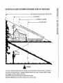
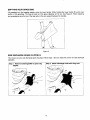
USE THIS PAGE AS A GUIDE
TO DETERMINE
SLOPES
WHERE
YOU MAY NOT OPERATE
SAFELY.
I
SIGHT AND HOLD THIS LEVEL WITH A VERTICAL TREE
I
A POWER POLE
Ill
r,o
Do not mow on inclines with a slope in excess of 15 degrees (a rise
could overturn and cause serious injury. If operating a walk-behind
your footing and you could slip, resulting in serious injury.
Operate RIDING mowers up and down slopes, never across the face
Operate WALK-BEHIND mowers across the face of slopes, never up
of approximately 2-1/2 feet every 10 feet). A riding mower
mower on such a slope, it is extremely difficult to maintain
of slopes.
and down slopes.
SECTION
2: IMPORTANT
SAFE OPERATION
PRACTICES
WARNING:
THIS SYMBOL POINTS OUT IMPORTANT SAFETY INSTRUCTIONS WHICH, IF NOT
FOLLOWED, COULD ENDANGER THE PERSONAL SAFETY AND/OR PROPERTY OF YOURSELF
AND OTHERS.
READ AND FOLLOW ALL INSTRUCTIONS
IN THIS MANUAL BEFORE
ATTEMPTING
TO OPERATE YOUR LAWN MOWER. FAILURE TO COMPLY WITH THESE
INSTRUCTIONS MAY RESULT IN PERSONAL INJURY. WHEN YOU SEE THIS SYMBOL, HEED ITS
WARNING.
DANGER:
Your lawn mower was built to be operated according to the rules for safe operation in this
manual. As with any type of power equipment, carelessness or error on the part of the operator can
result in serious injury. This lawn mower is capable of amputating hands and feet and throwing objects.
Failure to observe the following safety instructions could result in serious injury or death.
1. GENERAL
•
OPERATION
Read this owner's guide carefully in its entirety
before attempting to assemble this machine. Read,
understand,
and follow all instructions
on the
machine and in the manual(s) before operation. Be
completely familiar with the controls and the proper
use of this machine before operating iL Keep this
manual in a safe place for future and regular
reference and for ordering replacement parts.
•
Always wear safety glasses or safety goggles during
operation or while performing
an adjustment
or
repair, to protect eyes from foreign objects that may
be thrown from the machine in any direction.
•
Wear sturdy, rough-soled work shoes and closefitting slacks and shirts. Shirts and pants that cover
the arms and legs and steel-toed
shoes are
recommended. Do not wear loose fitting clothes or
jewelry. They can be caught in moving parts. Never
operate a unit in bare feet, sandals, slippery or light
weight (e.g. canvas) shoes.
• Your rotary mower is a precision piece of power
equipment,
not a plaything.
Therefore,
exercise
extreme caution at all times. Your unit has been
designed to perform one job: to mow grass.
use it for any other purpose.
•
•
•
Do not
° Do not put hands or feet near or under rotating parts.
Keep clear of discharge opening at all times as the
rotating blade can cause injury.
Never allow children under 14 years old to operate a
power mower. Children 14 years old and over should
only
operate
mower
under
close
parental
supervision.
Only responsible
individuals who are
familiar with these rules of safe operation should be
allowed to use your mower.
Keep the area of operation clear of all persons,
particularly small children and pets. Stop engine
when they are in the vicinity of your mower to help
prevent
blade contact
or thrown object injury.
Although the area of operation should be completely
cleared of foreign objects, an object may have been
overlooked and could be accidentally thrown by the
mower in any direction and cause serious personal
injury to the operator or any others allowed in the
area.
Thoroughly inspect the area where the equipment is
to be used. Remove all stones, sticks, wire, bones,
toys and other foreign objects which could be picked
up and thrown by the mower in any direction and
cause serious personal injury to the operator or any
others allowed in the area. Plan your mowing pattern
to avoid discharge
of material
toward
roads,
sidewalks, bystanders and the like. To help avoid a
thrown objects injury, keep children, bystanders and
helpers at least 75 feet from the mower while it is in
operation.
•
Many injuries occur as a result of the mower being
pulled over the foot during a fall. Do not hang on to
the mower if you are failing; reIease the handle
immediately.
•
Never pull the mower toward you while you are
walking. If you must back the mower away from a
wall or obstruction first look down and behind, and
then follow these steps:
•
Step back from the mower to fully extend your arms.
•
Be sure you are well balanced with sure footing.
•
Pull the mower back slowly, no more than half way
toward you,
•
Repeat these steps as needed.
•
Do not operate the mower while under the influence
of alcohol or drugs.
•
Do not engage the self-propelled
mechanism
units so equipped while starting engine.
on
• The blade control handle is a safety device. Never
attempt to bypass its operation. Doing so makes the
safety device inoperative and may result in personal
injury through contact with the rotating blade. The
blade control handle must operate easily in both
directions and automatically return to the disengaged
position when released.
3
•
Never operate the mower in wet grass. Aways be
sure of your footing. A slip and fail can caus_ serious
personal injury. Keep a firm hold on the h_ ndle and
walk, never run. If you feel you are Io,_ing your
footing, RELEASE THE BLADE CONTROL -{ANDLE
IMMEDIATELY and the blade wilI stop rotat ng within
three seconds.
•
Mow only in daylight or good artificial light.
•
Stop the blade when crossing gravel drives, walks or
roads.
•
Do not mow slopes greater
shown on the slope gauge.
•
Do not mow on wet grass.
cause slipping.
than
15 degrees
as
Reduced footing could
3. CHILDREN
Tragic accidents can occur if the operator is not alert to the
presence of children. Children are often attracted to the
mower and the mowing activity. Never assume that children
will remain where you last saw them.
o if the equipment should start to vibrate abnormally,
stop the engine and check immediately
for the
cause. Vibration is generally a warning of tro Jble.
•
Keep children out of the mowing area and under the
watchful care of a responsible adult other than the
operator.
•
•
Be alert and turn mower off if a child enters the area.
Shut the engine off and wait until the blade ;omes to
a complete stop before removing the gras:_ catcher
or unclogging the chute. The cutting blade +:ontinues
to rotate for a few seconds after the engin_ is shut
off. Never place any part of the body in tie blade
area until you are sure the blade has stopped
rotating.
Before and while moving backwards, look behind
and down for small children or other objects.
Never allow children under age 14 to operate the
mower. Children 14 years of age and above should
read and understand the operation instructions and
safety rules in this manual
•
Never operate mower without proper guards, grass
catcher, plates or other safety protective d)vices in
place.
•
Muffler and engine
burn. Do not touch.
•
Only use accessories approved for this m_chine by
the manufacturer. Read, understand, and 'ellow all
instructions provided with the approved acce _sory.
Use extreme care in handling gasoline and other
fuels. They are extremeIy flammable and the vapors
are explosive.
•
If situations occur which are not oovere J in this
manual, use care end good judgment. Cortact your
dealer for assistance.
Telephone 1-800-300-7310
for the name of your nearest dealer.
Use only an approved gasoline container.
2, SLOPE
become
Use extreme care when approaching blind corners,
shrubs, trees, or other objects that may obscure your
vision of a child or hazard.
hot and can cause a
4. SERVICE
Never remove gas cap or add fuel while the engine is
running. Allow engine to cool at least two minutes
before refueling.
OPERATION
Replace gasoline cap securely and wipe off any
spilled gasoline before starting the engine as it may
cause a fire or explosion.
For your safety, use the slope gauge included as p ]rt of this
manual to measure slopes before operating this mit on a
sloped or hilly area. If the slope is greater than 1_ degrees
as shown on the slope gauge, do not operate this unit on
that area or serious injury could result.
Extinguish all cigarettes,
sources of ignition.
Never
refuel machine
vapors will accumulate
DO:
•
Never
because
and
other
flammable
in the area.
the machine
or fuel
container
inside
Never run an engine inside a closed area.
• Watch for holes, ruts, hidden objects, or bu'nps. Tall
grass can hide obstacles.
To reduce fire hazard, keep mower free of grass,
leaves, or other debris build-up. Clean up oil or fuel
spillage. Allow mower to cool at least 5 minutes
before storing.
A slip and fall can
If you fee you are
blade contr 3I handle
stop in le,'s than 3
Before cleaning,
repairing,
or inspecting,
make
certain the blade and all moving parts have stopped.
Disconnect the spark plug wire, and keep the wire
away from the spark plug to prevent accidental
starting.
seconds.
DO NOT:
•
indoors
pipes
where there is an open flame or spark such as a gas
water heater, space heater, or furnace.
Mow across the face of slopes; never up aid down
Exercise extreme caution when changing direction
on slopes.
• Always be sure of your footing.
cause serious personal injury.
losing your balance release the
immediately and the blade will
store
cigars,
Check the blade and engine mounting bolts at
frequent intervals for proper tightness. Also, visually
inspect blade for damage (e.g., bent, cracked or
Do not mow near drop-offs, ditches or emb_ nkments.
The operator could lose footing or balance.
4
worn). Replace with blade which meets original
equipment specifications listed in this manual.
° Keep all nuts, bolts, and screws tight to be sure the
equipment is in safe working condition.
•
Never tamper with safety devices. Check their proper
operation regularly.
• After striking a foreign object, stop the engine,
remove the wire from the spark plug, and thoroughly
inspect the mower for any damage. Repair the
damage before starting and operating the mower,
•
Never attempt to make a wheel or cutting
adjustment while the engine is running.
height
Grass catcher components
are subject to wear,
damage
and deterioration,
which could expose
moving parts or allow objects to be thrown. For
safety protection, frequently check components and
replace with manufacturer's
recommended
parts,
when necessary.
Mower blades are sharp and can cut. Wrap the
blade(s) or wear gloves, and use extra caution when
servicing them.
Do not change the engine governor se_ing or
overspeed the engine. Excessive engine speeds are
dangerous,
read,
understand
and follow
the warnings and instructions
in this
and onmachine
the machine.
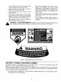
WARNING
- YOUR
RESPONSIBILITY:
Restrict the
use manual
of this power
to persons who
DANGER
WARNING
Figure 1 Safety Labels Found On Lawn Mower
SECTION
3: FINDING YOUR MODEL NUMBER
This Owner's Guide is an important part of your
maintain your mower. Please read and understand
Before you start to prepare your mower for its first
from it in this Owner's Guide. The information on
dealer or the MTD customer support department.
new lawn mower. It will help you assemble, prepare and
what it says.
use, please locate the model plate and copy the information
the model plate is very important if you need help from your
• Every mower has a model plate. You can locate it by standing behind the unit in the operating position
and looking down at the cutting deck.
• ThemodelplatewilllooklikeFigure2.
This is where your model number will be.
l
XXX-X-XXX-X-XXX
XXXXXXXXXXX
I
This is where your serial number will be.
Copy the model number here:
irlc
CLEVELAND,
OHIO 441 _6
Copy the serial number here:
Figure 2
SECTION
4: CALLING
CUSTOMER
SUPPORT
If you are having difficulty assembling this product or if you have any question regarding the controls, operation or
maintenance of this mower, please call the Ct stomer Support Department. You can reach them by calling:
1- 800-800-7310
Before you calI, make sure that you have b{,th your model and serial number ready. By having the model and
serial number ready, you help the Customer Support Representative give you faster service. To find your units
model and serial number, see SECTION 3: FI'4DING YOUR MODEL NUMBER.
SECTION
REMOVE
5: UNPACKING
INS"RUCTIONS
UNIT FROM CARTON
• See Figure 3.
• Remove staples, break glue on top flap_, or cut tape at carton end and peel along top flap to open carton.
• Remove loose parts if included with unii (i.e., owner's manual, etc.).
• Cut along dotted lines and lay carton d_wn flat.
• Remove packing material.
• Roll or slide unit out of carton. Check c lrton thoroughly for loose parts.
REMOVE MANUAL & LOOSE PARTS
Figure 3
6
DISCONNECT
SPARK
PLUG
WIRE
Before setting up your lawn mower, disconnect the spark plug wire from the spark plug, and ground it against the
engine by attaching rubber boot to a bolt or metal clip to the grounding post on the engine. See Figure 4.
Figure 4
SECTION
ITEMS
6: SET-UP INSTRUCTIONS
REQUIRED
FOR
ASSEMBLY
• Pair of Pliers (Not necessary, but helpful)
• Motor Oil
• Fresh Gasoline
IMPORTANT:
This unit is shipped WITHOUT GASOLINE or OIL in the engine. Be certain to service engine
with gasoline and oil as instructed in the separate engine manual before operating your mower.
NOTE:
Reference to right or left hand side of the mower is observed from the operating position.
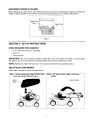
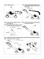
SET-UPYOUR
LAWN MOWER
Follow steps 1 through 9 to set-up your lawn mower.
Step 1. Remove grass bag (model 970-979 only)
from unit and set it out of the way.
Step 2. Lift upper handle. Align it with lower
handle.
Grass
Upper Handle
7
Step 4. Raise complete handle assembly until it
clicks into place. Make sure not to kinkthe
control cables.
Step 3. Tighten wing nuts.
HE11E
Handle Assembly
Step 5. Pinch lower handle against moun :ing
bracket with pliers.
Step 7. Attach control cables to handle with pull
ties found on the handle.
Step 6. Move hairpin clip from outer to in ler hole
on left and right handle mounting br ickets.
Inner Hole .......
_
Hairpn Clip
Pinch Here
\
Step 8. Squeeze the blade control handle against the upper handle and pull out starter rope, slowly!
Step 9. Thread starter rope into rope gui¢ e.
Blade C _ntrol Handle
Upper Handle
Model
970-979
ly
Start !r Rope
Look Here
Rope Guide
Model
950-959
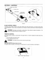
SECTION
7: CONTROLS
Blade Control Handle
Control
Cutting Height
Adjustment Lever
Drive
Clutch
Control
Figure 5
BLADE CONTROLHANDLE
The blade control handle is located on the upper handle of the mower. See Figure 5. The blade control handle
must be depressed in order to start and operate the unit. Release the bIade control handle to stop the engine and
blade,
blade
will be rotating
whenever
engineis is
WARNING:
The blade
controlthe
handle
a running.
safety device. Never attempt to bypass its operations.
THROTTLE
The
CONTROL
The throttle control is located on the left side of the upper handle. It is used to regulate the engine speed. See
Figure 5,
• Push the throttle lever forward for fast.
• Pull the throttle lever back for slow.
WARNING:
IGNITION
SWITCH
The throttle control cannot be used to stop the engine.
(Electric Start Unit Only)
The ignition switch is located on the left side of the handle panel. It is used for starting only, See Figure 6.
Ignition
.....• switch
Figure 6 Electric Start Unit Only
9
RECOIL
STARTER
The recoil starter handle is attached to the Io _er handle. See Figure 5. Stand behind the unit in the operating
position to start the unit.
DRIVE
CLUTCH
CONTROL
Squeezing the drive clutch control engages the,,drive system. Releasing the clutch control disengages the drive
system. Release the clutch control to slow dow ! when negotiating an obstacle, making a turn or stopping.
SHIFT
LEVER
The shift lever is located on the drive clutch co itrol housing on the upper handle. See Figure 5. This lever is used
to select the forward speed of the mower. Whe _ changing your speed selection, release the drive clutch control.
NOTE:
Only move the shift lever when the _ngine is running.
off can cause damage to the mower.
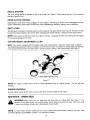
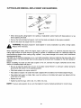
CUTTING
HEIGHT
ADJUSTMENT
Changing the shift lever setting with the engine
LEIER
Note: Your mower is shipped with the cutting height in the lowest position. Adjust the cutting height as follows.
The cutting height adjustment lever is located _bove the left rear wheel. To adjust the cutting height, pull the lever
out and away from the mower and then move i forward or back to select a new cutting height. See Figure 7.
LOWER
( ;utting Height Adjustment Lever
Figure 7
NOTE:
For rough or uneven lawns, move th_ height adjustment lever to a higher position.
This will help stop
scalping.
ENGINE CONTROLS
See the engine manual for the location and fur ction of the controls located on the engine.
SECTION
8: OPERATION
operation of any
lawnhands
mowerand
canfee
result
in foreign
objects
into the
eyes,
can1.result
WARNING:
Keep
away
from the
chutebeing
area thrown
on cutting
deck.
Seewhich
Figure
The
in severe eye damage. Always wear _afety glasses or eye shields.
NOTE: For best results raise the cutting po:_ition until it is determined which height is best for your lawn. See
CUTTING HEIGHT ADJUSTMENT
LEVER in he CONTROLS section.
10
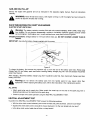
GAS
AND
OIL FILL-UP
Service the engine with gasoline and oil as instructed in the separate
carefully.
,_
engine manual. Read all instructions
cool
for at leastNever
two minutes
WARNING:
fill fuel after
tank running.
indoors, with engine running or until the engine has been allowed to
EACH TIME BEFORE YOU START
ELECTRIC START UNITS ONLY:
YOUR
MOWER
from children.The
Warning:
Dobattery
not puncture
containsdisassemble,
corrosive fluid
mutilate
and toxic
or incinerate.
material-HANDLE
Explosive WITH
gasses
CARE.
could Keep
be vented
away
during charging or discharging, use in a well ventilated area, away from sources of ignition,
Charging Instructions:
HOURS.
IMPORTANT:
Charge battery for 16 hours before initial use. DO NOT CHARGE
Use only the battery chargerwitsupplied
h this mower.
LONGER THAN 20
_.
Figure 8
To charge the battery, first remove the protective cap (1) from the end of the battery pack lead. Always plug
charger lead (2) into battery pack lead before inserting battery charger plug into 120 volt standard household
outlet. See Figure 8.
After charging, disconnect
battery pack lead.
,_
battery charger plug from household outlet first, than disconnect charger lead from
Warning: Do
replacemenL
When
not replacing
remove the
the battery
batterypack,
packrefer
from
to the
the instructions
handle panel
in theformaintenance
any reasonsection.
other than
ALL UNITS:
• Attach spark plug wire to spark plug. Make certain the metal cap on the end of the spark plug wire is
fastened securely over the metal tip on the spark plug.
• Check for proper drive clutch operation using the NEUTRAL ADJUSTMENT TEST.
NEUTRAL
ADJUSTMENT
TEST
To perform the NEUTRAL ADJUSTMENT
TEST answer the following questions.
• With the drive clutch control released, push mower forward and pull it backward.
• Squeeze the drive clutch control and pull the mower backward.
• Is the drive clutch control cable free of kinks or sharp bends?
11
Does it move freely?
Do the rear wheels lock (net turn)?
If youanswered"yes"to all threequestions,y_urmowerpassed
the test and you can start your mower. If you
answered "no" to any of the three questions, you need to go through the DRIVE CLUTCH CONTROL
ADJUSTMENT found in the ADJUSTMENTS s, ,_ction.
TO START ENGINE
AND ENGAGE
BI,ADE
• Move the throttle control lever all the wa_ forward.
• Prime engine as instructed in the separa e engine manual.
• Stand behind the unit, squeeze and hold the blade control handle against the upper handle.
• Electric
starts.
Start unit: Turn the ignition ke t to the right to start the engine. Release the key after the engine
• Recoil Start: Grasp starter handle and pull rope out slowly until engine reaches start of compression cycle
(rope will pull slightly harder at this point. Let the rope rewind slowly. Pull rope with a rapid, continuous, full
arm stroke. Keep a firm grip on starter h_halle. Return it slowly to the rope guide.
• After engine starts, move throttle centre to desired engine speed. (The mower is designed to be operated
at full throttle.)
NOTE: If any problems are encountered, refe" to the TROUBLE SHOOTING Section of this manual.
TO STOP
ENGINE
AND
BLADE
• Release the blade control handle to stop the engine and blade.
,_
WARNING:
The blade continues tc rotate for a few seconds after the engine is shut off.
USING YOUR ROTARY MOWER
Be sure that lawn is clear of stones, sticks, wir _, or other objects which could damage the lawn mower or engine.
Such objects could be accidently thrown by tLs mower in any direction and cause serious personal injury to the
operator and others.
For the best results, do not cut wet grass because it tends to stick to the underside of the mower, preventing
proper discharge of grass clippings, and coul:l cause you to slip and fall. New grass, thick grass or wet grass
may require a narrower cut.
For a healthier lawn, never cut off more than c ne-third of the total length of the grass. Your lawn should be cut in
the fall as long as there is growth.
This mower is designed to be operated at ful throttle to give you the best cut and do the most effective job of
mowing or mulching.
,_
inspect the mower
any damage,
repair
damage
restarting
and spark
operating
mower.
WARNING:
If youforstrike
a foreign ]nd
object,
stopthethe
engine. before
Remove
wire from
plug, the
thoroughly
Extensive vibration of the mower curing operation is an indication of damage. The unit should be
promptly inspected and repaired.
12
BAGGING
GRASS
CLIPPINGS
(Model
979 Only)
This mower can bag grass clippings. FoI!ow steps 1 through 3 to ready the mower for bagging.
Step 1. Remove wing nuts holding mulching
baffle or side discharge chute in place. Then
remove plug or discharge chute.
Step 2. Replace with bagging adapter. Attach
using wing nuts. Be sure that inner lip of
attachment goes under the edge of the deck.
.....
.I
Step 3. Lift flap and slide bag onto adapter.
t
Bagging
adaptor
Mulching
baffle
Side discharge
13
chute
EMPTYING
YOUR
GRASS
BAG
Lift grassbag from the bagging adaptor using the lower handle. While holding the lower handle lift up the rear
section of the grassbag. The bag will open a_d the grass clippings will fall out. See Figure 9. When replacing
your grassbag be sure the top of the bag rests on the wire support between the handles,
Figure 9
SIDE
DISCHARGE
GRASS
CLIPPIN¢
iS
This mower can also side discharge grass cli_ pings. Follow steps 1 and 2 to ready this mower for side discharge
operation.
Step 1. Remove mulching baffle or grass bag
adapter.
Step 2. Attach discharge chute with wing nuts.
14
SECTION
9: ADJUSTMENTS
disconnecting
wire.time make any adjustment to lawn mower without first stopping engine and
WARNING: spark
Do notplug
at any
,_
HANDLE
HEIGHT
ADJUSTMENT
Noah
Lower Handle
Figure 10
Your mower is shipped with the handle in the higher height position. To lower handle height, proceed as follows:
• Remove the starter rope from the rope guide.
• Remove the upper handle by removing the hand knobs and carriage bolts. Lay the upper handle out of the
way, being careful not to bend or kink the cables.
• Remove the hairpin clips from the weld pins on the handle brackets.
handle. Remove lower handle from the mower.
Press out on the legs of the lower
• Turn lower handle around so the notch on the bottom of the lower handle is facing forward. See Figure 10.
Reassemble, placing the bottom holes in the handle over the weld pins in the handle mounting bracket.
• Reassemble the upper handle to the lower handle.
• Place the hairpin clips in the inner holes in the weld pins and attach the starter rope as instructed in the SetUp Instructions.
THROTTLE
CONTROL
ADJUSTMENT
Clamp
On Engine
Figure 11
If the throttle control requires adjustment or if it has been replaced, adjust the throttle control as follows.
• Remove the screw shown in Figure 11. Remove the cable clamp from the cable.
• Push the throttle control lever on the handle all the way forward as far as it will go, then back it off one
"click". Make certain the throttle control lever remains in this position.
• Push the control lever on the engine as far toward the rear of the engine as it will go. Secure the cable in
this position with the cable clamp and screw.
15
DRIVE CLUTCH
CONTROL
ADJUSTI AENT
The drive clutch control adjustment wheel is located in the drive clutch control handle housing and is used to
tighten or loosen the drive belt. You will have o adjust the drive clutch control if any of the following happens:
• The mower does not propel itself with th ._drive clutch engaged.
• The mower's drive wheels hesitate with he drive clutch engaged.
To resolve the above problems, rotate the adj_tstment wheel with your fingers. Clockwise to tighten the cable and
counter-clockwise to loosen the cable. See Fig Jre 12.
Bottom View
®
®
Adjustment
Wheel \
\
Figure 12
Note: For some people the drive clutch hand e may not be in a comfortable position.
out by tightening the adjustment wheel.
Follow engine manual for lubrication instructior s.
SHIFT
LEVER CABLE
You can adjust the handle
ADJUSTMEN1
Periodic adjustment of the six speed shift cabl ._may be required due to normal wear on the cable. Adjustment is
needed if all six speeds do not work.
The adjustable cable bracket is located on the left side of the mower, beside the engine. Follow steps 1 through
7 to adjust the shift lever.
I
Bottom View
Adjustable Cable Bracket
®
Hex Nut (A)
Speed C, }ntrol
Lever
Step 1. Start engine.
Step 2, Place speed control in the sixth sp.=ed
position.
Step 3. Stop engine.
Step 5. Loosen hex nut (A) which secures the
adjustable cable bracket.
Step 6, Push back on the adjustable cable bracket.
Step 7. Tighten hex nut (A).
Step 4. Disconnect spark plug wire and gr,)und it.
16
SECTION
10: MAINTENANCE
maintenance.
WARNING:
_,
Be sure to disconnect and ground the spark plug wire before performing any repairs or
NOTE: When tipping the unit, empty the fuel tank and keep engine, spark plug side up. Never tip the mower
more than 90 degrees and do not leave the mower tipped for any length of time. Oil can drain into the upper part
of the engine causing a starting problem.
ENGINE
Refer to the separate engine manual for all engine maintenance instructions.
• Maintain engine oil as instructed in the separate engine manual packed with your unit. Read and follow
instructions carefully.
• Service air cleaner every 25 hours under normal conditions. Clean every few hours under extremely dusty
conditions. Poor engine performance and flooding usually indicates that the air cleaner should be serviced.
To service the air cleaner, refer to the separate engine manual packed with your unit.
• The spark plug should be cleaned and the gap reset once a season. Spark plug replacement is
recommended at the start of each mowing season; check engine manual for correct plug type and gap
specifications.
• Clean the engine regularly with a cloth or brush. Keep the cooling system (blower housing area) clean to
permit proper air circulation which is essential to engine performance and life. Be certain to remove all
grass, dirt and combustible debris from muffler area.
DECK
The underside of the mower deck should be cleaned after each use to prevent a buildup of grass clippings,
leaves, dirt or other matter. If this debris is allowed to accumulate, it will invite rust and corrosion, and may
prevent proper mulching, discharge or bagging.
The deck may be cleaned by tilting the mower and scraping clean with a suitable tool (make certain the spark
plug wire is disconnected).
ELECTRIC
BATIERY
START
UNITS
ONLY:
PACK REPLACEMENT
Remove the battery pack from the handle panel for replacement
reason. Dispose of batteries properly.
_,
only. Do not separate the batteries
for any
any way. Do not
put batteries
in fire.
Theyacid
maywhich
burst may
or release
WARNING:
Batteries
contain
sulfuric
cause toxic
burns.materials.
Do not short circuit or mutilate in
When replacing battery pack in handle panel, battery pack must be positioned with the positive terminal to the
right hand side and the negative terminal to the left hand side of panel. Replacing the battery pack incorrectly will
cause serious damage.
The positive lead on the wire harness has the smaller connector. Connect the positive lead to the positive side of
the battery pack, then connect the negative side.
IN-LINE FUSE
The unit is equipped with an in-line fuse. If unit fails to start, check the fuse inside the battery cover by turning the
end of the fuse holder and removing from the battery cover. Replace with standard automotive 7-1/2 amp fuse.
STORAGE
OF THE
BATTERY
The battery must be stored with a full charge. A discharged battery will freeze.
IMPORTANT:
All batteries discharge during storage. Recharge battery
returning to service. Refer to charging instructions in OPERATION section.
17
every two months
and before
CUTTING
BLADE
REMOVAL,
REPLA _EMENT
AND SHARPENING
Blade
Adapter ""
Blade Bell
Support
Figure 13
• When removing the cutting blade for Sh_Lrpening or replacement, protect hands with heavy gloves or a rag
before grabbing the blade.
• Remove the bolt and blade bell support \ zhich hold the blade and adapter to the engine crankshaft.
• Remove the blade and adapter from the _rankshaft.
_,
Replace
when necessary,
WARNING:
Periodically inspect th_ blade adapter for cracks, especially if you strike a foreign object.
When sharpening the blade, follow the origin _1angle of grind as a guide. It is extremely important that each
cutting edge receives an equal amount of gri _ding to prevent an unbalanced blade. An unbalanced blade will
cause excessive vibration when rotating at hig 1 speeds. It may cause damage to the mower, and it could break
causing personal injury.
The blade can be tested by balancing it on a r_und shaft screwdriver. Remove metal from the heavy side until it
balances evenly. It is recommended that the bade always be removed from the adapter for the when testing for
balance,
Before reinstalling the blade and the blade aJapter to the unit, lubricate the engine crankshaft
surface of the blade adapter with light oil.
and the inner
• Be sure to install the blade with the site of the blade marked "Bottom" (or with part number) facing the
ground when the mower is in the operatil _gposition.
• Slide blade adapter onto engine cranksh #t.
• Place blade on adapter,
Be certain the L lade is aligned with and seated onto the blade adapter flanges.
• Place blade bell support on blade. Mak ; sure the notches on the blade bell support are aligned with the
small holes in the blade.
• Replace hex bolt.
• Tighten hex bolt to torque: 450 in. Ibs. n'in., 600 in. Ibs, max.
NOTE: To ensure safe operation of your unit, the blade bolt must be checked periodically for correct torque.
18
DRIVE BELT REMOVAL
AND REPLACEMENT
Step 1. Disconnect the spark plug wire and ground
it against the engine.
Step 9. Remove the hex bolt holding the
transmission to the mower housing.
Step 2. Drain the fuel tank or place a piece of
plastic beneath the cap to prevent gasoline
leakage.
Step 3. Place shift lever in the first position.
Step 4. Tip the mower on its side. Block securely.
Step 5. Remove the center bolt which secures the
blade to the crankshaft. Remove the blade,
and the blade adapter, wave washer, and
spacer. Refer to Cutting Blade Removal,
Replacement and Sharpening in the
Maintenance Section.
Hex Bolt
Baffle
Step 6. Move rear height adjuster to the sixth
position.
Step 7. Using a 3/8" socket, remove three hex
screws holding the baffle to the deck.
Step 10. Tilt the transmission forward and loosen
the idler pulley bolt and Iocknut 1/2 turn
using two 7/16" wrenches.
Step 11. Using a pair of pliers, pull back and rotate
belt keeper bracket from the slot on idler
pulley.
HexScrew
Step 12. Slide the belt out from between the Belt
Keeper Bracket and the idler pulley.
Transmission
Hex Scre_
Hex
Screw
Pulley
_ I
_
Belt
Belt Keeper _
Bracket
Idler Pulley /
Step 8. Pivot baffle towards the rear of the mower.
Transmission
Bracket
/
Idler Pulley
J
I
Boltand /
Locknut
\
19
_ep
13, S_e
the heather
andpu _h-belt
forward. Press the control arm inwar _
towards the deck and remove the sb speed
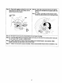
i Steplp161 Place_e
new beito_er the tran_n-I
pulley. Start the belt in pulley groove and
!
rotate pulley until belt is seated in
cable from the slot.
Six-Speed
Cable Slot
transmission pulley.
Step 17. Place belt between dier pulley and the
belt keeper bracket.
Belt
Step 18. Using pliers, rotate the belt keeper
bracket so that it snaps into slot on the id er
Control
Arm
bracket,
Step 19. Tighten the Idler Pulley bolt and Locknut
112 turn using two 7/16" wrenches.
Transmission
Pulley
_
Belt Keeper
Bracket
Step 14. Pivot the control arm down away from the
Transmission
pulley and belt.
Idler Pulley
Boltand /
Locknut
/ _....
( :ontrol
Arm
IStep 15. Lift off the lower pulley assembl' r and
remove the old belt from around the
crankshaft.
Step 20. Place belt between the two pulley halves
on the crankshaft. Make sure to route the belt
inside the belt guard pin.
"
Lower Pulley
o
o
Upper
Pulley
Half
Half_
•Cranks haft
Tab
Belt
Belt
Belt
Pin
.....................
Lower
Pulley
Half
ilMPORTANT: When replacing the belt, do not disas_semble
the lower pulley
assembly.
"
....
2O
Step 21. Pinch belt together so that it is not in the
pulley groove, and the lower pulley can be
pushed towards the engine.
Step 22. Pivot the control arm back to its original
position and reinstall the six-speed cable into
the slot.
Step 23. Check and make sure the belt is routed
inside the pulley halves and the belt guard pin.
Lower Pulley
Half
\
o
,, \ \
o
Guard
Pin
Step 24. Reinstall the bolt securing transmission to rear mower housing.
Step 25. Pivot the baffle back to its original position and secure with three hex screws earlier removed.
You will need a 3/8" socket for these screws.
Step 26. Lightly lubricate the inside of the blade adapter and reinstall spacer, wave washer, blade
adapter assembly and the blade in the correct order.
Step 27, Tighten the hex bolt to secure the blade. Follow recommended
21
torque which is 450-600 in. Ibs.
SECTION
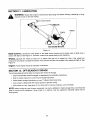
11: LUBRICATION
any
kind of workAlways
on the stop
lawnengine
mower.a _d disconnect spark plug wire before cleaning, lubricating or doing
WARNING:
Ble(e Control Handle
Wheels
)ine
/
SEE ENGINE MANUAL
Figure 14
Blade Control:
Lubricate the pivot points on the blade control handle and the brake cable at least once a
season with light oil. See Figure 14. The blad_ control must operate freely in both directions.
Wheels: Lubricate the wheels at least on :e a season with light oil (or engine oil). Also, if the wheels are
removed for any reason, lubricate the surface of the axle belt and the inner surface of the wheel with light oil. See
Figure 14.
Engine:
Follow engine manual for lubricatic _ instructions.
SECTION
12: OFF-SEASON
s'rORAGE
The following steps should be taken to prepal s lawn mower for storage.
• Clean and lubricate mower thoroughly
*s described in the lubrication instructions.
• Refer to engine manual for correct eng ne storage instructions.
• Follow battery storage instructions on _ age 17 (Electric Start Units Only).
• Coat mower's cutting blade with chassis grease to prevent rusting,
• Store mower in a dry, clean area. Do n )t store next to corrosive materials, such as fertilizer.
NOTE: When storing any type of power eqqlipment in a poorly ventilated or metal storage shed, care should be
taken to rust-proof the equipment.
moving paris.
Using a light oiI or silicone, coat the equipment,
22
especially cables and all
SECTION
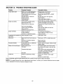
13: TROUBLE
Trouble
Engine fails to start
Engine runs erratic
SHOOTING
GUIDE
Corrective Action
Possible Cause(s)
Blade control handle disengaged.
Spark plug wire disconnected.
Throttle control lever not in correct
starting position.
Fuel tank empty, or stale fuel.
Blocked fuel line,
Faulty spark plug.
Engine flooded,
Engage blade control handle,
Connect wire to spark plug.
Move throttle lever to FAST or START
3osition.
Fill tank with clean, fresh gasoline.
Clean fuel line,
Unit running in START position.
Spark plug wire loose.
Blocked fuel line or stale fuel.
Move throttle lever to FAST position.
Connect and tighten spark plug wire,
Clean fuel line; fill tank with clean, fresh
gasoline.
Clear vent.
Drain fuel tank, Refill with fresh fuel.
Clean air cleaner.
Vent in gas cap plugged.
Water or dirt in fuel system,
Dirty air cleaner.
Carburetor out of adjustment.
Engine overheats
Engine oil level low.
Air flow restricted.
Carburetor net adjusted properly,
Clean, adjust gap or replace.
Crank engine with throttle in FAST position,
Adjust carburetor.
Fill crankcase with proper oil.
Remove blower housing and clean.
iAdjust carburetor.
Occasional skip (hesitates) at Spark plug gap too close.
high speed
Adjust gap to .030".
Idles poorly
Spark plug fouled, faulty or gap too
wide.
Reset gap to .030" or replace spark plug.
Carburetor improperly adjusted.
Dirty air cleaner.
Adjust carburetor.
Clean air cleaner.
Excessive vibration
Cutting blade loose or unbalanced,
Bent cutting blade.
Tighten blade and adapter. Balance blade.
Replace blade.
Mower will not mulch grass
Engine speed too low.
Wet grass.
Set throttle between 3/4 and full throttle.
Do not mow when grass is wet; wait until
later to cut.
Excessively
high grass,
Mow once at a high cutting height, then
mow again at desired height or make a
narrower cutting swath (1/2 width).
Sharpen or replace blade.
Dull blade.
Uneven cut
Wheels not positioned correctly.
Dul! blade.
Place all four wheels in same height
}osition.
Sharpen or replace blade.
Refer to separate engine manual packed with your mower for more engine rebated information.
NOTE: For repairs beyond the minor adjustments listed above, contact your nearest authorized service dealer
or call 1-800-800-7310 for the Customer Support Center.
23
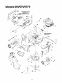
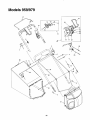
Models 959/979/E.q79
TRANSMISSIC N AND
PULLEY F 3R
64
/
Y
32
/
38
/
62
63
6O
\
\
\\
45
39
37
73
2
6
25
6
16
61
74
43
42
43
8O
\
\
79
77
9
8
10
5O 52
8
\\
76
\
54
68
24
53
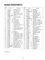
Models 959/979/E979
Ref.
No.
Part No.
Ref.
No.
Description
1
710-0134
Scr. Carr. 1/4-20 x .62
2
710-0654A
Scr. _:3/8-18:1.00
3
4
710-0703
712-0397
Scr. 1/4-20 x .750
5
723-0233
6
736-0204
7
782-0046-0665
8
710-0653
N
Part No.
Description
Traii-S
40
41
42
731-1901
732-O842
611-0064-0665
Wing Nut 1/4-20
Nut, Push .25 I.D. x ,50 O.D.
43
710-1241
F£ Axle Ass'y.
Hx Scr. Wash Hd. HL-Lo.
44
710-1242
Scr. Torx, Truss HL-Lo.
Wash. FL .334 LD.x .62 x.03
Deck - 21"
45
714-0104
46
731-1829
Scr. TT. 1/4-20 x .375
47
736-0286
N
N
Trail Shield Wire
Cotter Pin .072 x 1.12 Lg.
N
Fr, Axle Cover, Yellow
Bowed Washer
9
710-1220
Scr. HE 1/2-14 x .750
48
741-0492A
10
731-1828
N
Baffle
49
782-0565-0665
N
ControI Arm
11
638-0012
N
Rear Axle Ass'y
50
734-1818
N
WheeI 8 x 2 Link, Yellow
12
682-0531
N
Pivot Arm Ass'y
51
734-1836
N
WheeI 9 x 2 Link Yellow, Sly.
13
682-7526
N
Trans. Axle Ass'y
52
736-0105
14
682-7528
N
53
736-0504
Spr. Wash..401 x .870 x .063
Wave Wash .510 x .750 x .017
15
710-0653
Chain Cover Ass'y
Scr. 1-1-1/4-20 x .375
54
738-0102
Shldr Scr .498 x 1.445 x3/8-16
16
710-0751
55
10622B
17
710-0896
Cap Screw HH 1/4-20 x .620
Scr. AB 1/4-14 x .826
56
748-0381
Spring, Ratchet, Plastic
Pawl - R.H.
18
710-1315
Scr. 3/8 116 x .25
57
748-0188B
19
711-0635
58
16855
Pawl - L.H. (Not Illustrated)
Ratchet Pawt Plate
20
713-0453
Clevis Pin .50 Dia. x 4.82 Lg.
Chain-Endls. #48.500P x 24L
59
738-0137A
Scr. Shld, .340 x ,285
21
714-0474
Cotter Pin .1250.D. x .75
60
712-0414
Top Lock Tab Weld Nut 1/4-20
22
720-0223
Grip
61
731-1426
23
732-0803
N
Spring Lever
62
710-1237
Hubcap -Yellow
Screw .620 Hx. Sit. Wsh.
24
732-0832
N
751B213146
736-0270
Torsion Spring
Bell Wash..285
63
25
64
725-0157
26
736-0369
FI. Wash..508 I.D. 1.000 x.020
65
710-0604
27
738-0529
Nut Shld..825
Dia. x .165 Lg.
66
754-0460
28
741-0324
Hx.FIg. Brg..506 I.D, x .590 L
67
742-0741
21" Mulching Blade
29
741-0522
68
753-0609
Blade Adaptor Kit
30
741-0978
69
736-0524A
Blade Bell Suport
31
748-0318
Hx.Flg. Brg..506 I,D. x.715 L.
Hx. SIv. Brg..504 I,D. x ,830 L.
Wheel Rachet
7O
710-1257
Hex Bolt 3/8-24x2.5"Lg.
32
750-0151
Spa..550
72
735-0639
33
750-0515
Spa..51
73
731-1832
N
34
35
750-0807
Spa, ,385 x .624 x .700
74
731-1833
N
Side Discharge Chute
Mulch Cover
N
N
x .75 x .082
I.D. x/750 O.D.
.D. x .70 O.D. x 38 L.
Bush. Block .505 Dia. x .62
Casing Clamp, Throttle
Cable Tie
Hex Scr. 5/16-18
N
Belt
Spark Plug Insulator
750-1056
782-0568
N
N
Shld. Spa..385 I.D, X .715 Lg.
Brkt. - Ht, Adj. Spring
75
631-0066
N
Chute Ass'y
36
37
76
I 731-1713
N
Discharge Chute l"t
682-3052-0665
N
Handle Brkt. Ass'y. R.H.
77
I 747-0965
N
Pivot Rod tl-
682-3053-0665
710-1348
N
Handle Brkt. Ass'y. L.H.
Scr. AB 1/4-14 x .500
78
t 732-0819
N
Torsion Spring tt
79
80
I 726-0111
731-1874
1........
N
Push Cap t"1"
ft
c.ut Doer .....
39
38
.
11" Model 979 only
25
tt
Models 959/979
27
24
23
13
19
17
3
26
5
7
36
\
3
4
\
5
3O
31
26
22
Models 959/979
Rt,_.f"
Ref,
No.
Description
Part No.
Part No.
Description
19
714-0104
720-0241
726-0240
I Cotter Pin .072 x 1.12 Lg.
Knob Ass-'y Wingnut 5/16-18
C Sunk Tap Screw #10 x 175 L
20
732-0627
Shift Lever Spring
21
16864
6 Spd. Rack CabIe Brkt,
22
731-0905
Lower Control Housing
23
731-0906
Cable Mounting Cap
Contro! Lever
5
736-0451
Strap 4.3 Lg.
Wash. Sad..320
6
720-0279
Knob Handle ERS - 1/4-20
24
731-0620
7
710-1205
746-0939
710-0605
Rope Guide Eyebolt
Screw 1/4-20 x 1.81
25
8
746-0710A
6 Spd, Cable
S,R Cable
Throttle Lever
26
27
747-0824
Control Handle
90
746-0876
736-0501
Spring Wash.Curved
28
720-0294
Foam Grip (2 Reqd.)
11
712-0324
Nut 1/4-20 Top Iocknut Insert
749-0439B
12
646-0875
Upper Handle
Lower Handle
13
811-00303
Housing, Throttle
Throttle Control - (Includes
8,9,10,11 & 12)
29
30
31
631-0071
N
Grassbag Cover w/Label 11
14
746-0557
Control Cable 47" Lg.
Cable Throttle 60" Lg.
32
747-0939
N
33
726-0106
Pivot Rod tt
Cap Nut tt
Upper Control
34
747-0937
N
Frame - Grassbag t1.
35
747-0940
664-0074
N
Rod, Support 1.'_
15
16
i 746-0841
731-0904
17
731-0924
18
ID x.830 OD
1"
Housing
6 Speed Shift Lever
Gear Insert
I 713-0397
36
N
749-0907
Ni Grassbag tt
' For model 959 only
tt For model 979 onl
Labels
Ref
No.
Part No.
N!I
777-1595C
N/I
777-0870
N/I
777-5270
N/I
777-1104
N/]
777-8627
N/I
N/I
777-0148
777-4466
N/I
777-4569
Ref
No.
Description
N
N
N
Pa_ No,
Description
Danger - Rt. Rear
Nil
777-4626
N
YM 6/21 LabeI 1"
Danger - Side Discharge
Nil
777-4627
N
YM 6/21 LabeI 1"1"
Warning - Above Deck
Opening
Drive Label
Nil
777-4628
N
YM 6/21 Label :):
Nil
777-5645
N
Drive Label $
Throttle Label
YM Bubble Crest
N/I
777-1183A
Ht. Adjuster Label
Model No. Label
Nil
777-3541
Nil
777-1105
N
Start Instructions
tery Pack :]:
WheeI Cover Label
Nil
777-4629
N
YM Electric Start :1:
1 For model 959 only
11 For model 979 only
:1:For model E979 only
27
Trans. Drive Label
- on Bat-
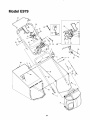
Model E979
16
29
-----2!
37
53
\
19
43
17
22
3
26
4
36
3
31
28
25
Model E979
Ref.
No.
Part No.
Ref.
No.
Description
Part No.
Description
1
710-1174
Bolt Cur. Carr. 5/16-18 x 2.0
29
749-0439B
2
714-0104
Cotter Pin .072 x 1.12 Lg.
30
749-0907
3
720-0241
Knob Ass'y Wingnut 5/16-18
31
631-0071
4
726-0240
32
747-0939
5
736-0451
Strap 4.3 Lg.
Wash. Sad. ,320 ID x,830 OD
33
726-0106
6
720-0279
Knob Handle ERS - 1/4-20
34
747-0937
N
Frame - Grassbag
9
746-0876
Throttle Lever
35
747-0940
N
Rod, Support
10
736-0501
Spring Wash.Curved
712-0324
Nut 1/4-20 Top Iocknut Insert
664-0074
710-1250
N
11
36
37
Grassbag
Cur, Carr. Bolt 5/16-18 x 1"
12
646-0875
712-0267
Lg.
Hex Nut 5/16-18 Thd.
13
811-00303
Housing, Throttle
Throttle Controt - (Includes
9,10,11 & 12)
38
39
725-1276
Battery Pack - 12 Volt
14
746-0557
ControI Cable 47" Lg.
40
731-0891A
Battery Tray
15
746-0841
Cable Throttle 60" Lg.
41
725-0873
Ignition Switch
16
731-0904
Upper Control
42
725-0201
17
731-0924
6 Speed Shift Lever
43
425-1428
725-0298
Ignition Key
Fuse Holder
Fuse 7-1/2 Amp (Not IlL)
18
713-0397
Gear Insert
44
725-1206
19
710-0841
C Sunk Tap Screw #10 x .75 L
45
725-1442
20
732-0627
16864
Shift Lever Spring
6 Spd. Rack Cable Brkt.
46
47
710-0501
21
736-0270
Hex Bolt 1/4-20 x 2" Lg.
Bell Wash 1/4" I,D.
22
23
731-0905
731-0906
Lower Control Housing
49
50
782-9012
736-0242
Lower Battery Tray
Bell Wash. 5/16" I.D.
24
731-0620
25
_746-0939
26
I 746-0710A
27
747-0824
Housing
Cable Mounting Cap
Controi Lever
Upper Handle
Lower Handle
N
N
Gressbag Cover w/Labei
Pivot Rod
Cap Nut
Plug
Wire Harness
51
710-0969
6 Spd. Cable
S,R Cable
52
725-1538
Truss Mch. Tap Scr. 1" Lg.
Harness Ext.
53
710-0111
Scr. 1/4-20 x 1.25
Control Handle
54
712-0287
Hex Nut 1/4-20
FoamGr!p!2Re.qd:!....
55
725-0727
Battery Charger
29
Models 959/979/E' )79
8
6
13
2
9
16
18
/
17
7
Ref.
No.
Par No.
Description
6 Spd. Cabie-
1
2
746-093:)
656-061
3
710-016 '
4
710-089,_
5
711-111 _
6
712-028 '
Nut 1/4-20
7
732-080 '
8
736-027' )
Torsion Spring LH
Bell Wash..265 X .75 X .062
N
Pulley Ass'y Multi- Spd.
Scr, 1/4-20 x .50 Carr.
Scr, AB 1/4-14 x ,625 Hxinwsh
N
Pivot Shaft
9
736-O32 )
10
736-052,
11
738-092
Lock Wash. 1/4 Reg Duty
Wave Wash. 1.38 x .88 x ,029
Shld,Scr, ,375 xli4-14AB
12
750-107 )
Slev Spcr .88 IDxl.00
13
14
750-107
756-062
Slev Spcr .881D xl.131D x .12
Roller Cable
15
782-757 _.-0665 N
6 Spd. Cable Adj. Bracket
16
782-757 5-0665 N
6 Spd. Cable Mt. Bracket
17
782-759 _
N
18
782-759 '
N
19
712-013
6 Sp. Control Arm
6 Sp. Pivot Bracket
Hex Nut 1/4-28
30
OD x.48
Models 959/979/E979
5_
_4
22
24 /
27
.........
No.
Rei-I
No."
Description
-1"_
Hx. Jam Nt_t-_
2
3
4
I 736-0425
I 756-0856
736-3084
5
712-0896
6
782-7598
N
7
8
741-0600
750-1050
N
9
682-0027
N
N
17
Description
Part NO.
J
I 717-1468
N
Pinion Shaft 10T,
Thr. Wash. 3/8 x .70 x ,030
Bell Wash..325 x .930 x .045
Pulley
FL Wash..510 x 1,120 x .060
18
19
20
I 736-0314
I 736-0569
I 618-0252
N
N
Thr. Wash..388
Hx. Jam Nut 1/4-28
21
Belt Keeper
22
I 710-0642
] 782-7601
N
Cable Bracket
Bearing
23
24
] 741-0674
I 611-0066
N
Bearing
Flange Spacer
N
Shaft Ass'y.
Idler Bracket Ass'y.
25
I 721-0325
I 717-1469
N
Plug
Gear 34 T,
26
27
x ,625 x .062
Lower Housing Ass'y.
Hx. Scr. 1/2-20 x .75
I(
710-0299
I1
732-0811
N
Torsion Spring
I 711-1168
N
Output Shaft 6 T.
If
741-0682
! 741-0673
N
736-0570
Bearing Sleeve
FI. Wash. ,885 x 1.145 x.030
28
I_
N
N
29
721-0329
Flange Bearing
Oil Seal
lz
t_
721-0329
618-0253
Oil Seal
30
782-7595
Pivot Bracket
741-0324
736-0520
Upper Housing Ass'y.
FI. Wash..504 x .700 x .030
31
1_
32
736-0369
Flange Bearing
Wash, FI. ,508 I.D. x 1.00 O.D. x
,020
618-0263
Tranmission Cemp.
Hx. Cap Scr. 1/4-28 x 1.00 Gr. 5
N
N
I
31
32
33
34
MANUFACTURER'S
LIMITED WARRANTY
FOR"
YaRD-MaN)//
For TWO YEARS from the date of retail purchase within the United States of America, its possessions and
territories, MTD Products will, at its option, repair or replace, for the original purchaser, free of charge, any part or
parts found to be defective in material or workmanship. This warranty covers units which have been operated and
maintained in accordance with the owner's instructions furnished with the unit, and which have not been subject
to misuse, abuse, commercial use, neglect, accident, improper maintenance or alteration.
Normal wear parts or components thereof are subject to separate terms as noted below in the "No Fault Ninety
Day Consumer Warranty" clause.
All normal wear part failures will be covered on this product for a period of 90 days regardless of cause. After 90
days, but within the two year period, normal wear parts failures will be covered ONLY IF caused by defects in
material or workmanship of OTHER component parts. Normal wear parts are defined as battedes*, belts, blades,
blade adapters, grass bags, rider deck wheels, seats, snow thrower skid shoes, shave plates and tires.
How to obtain service: Warranty service is available, with proof of purchase, through your local authorized
service dealer. To locate the dealer in your area, please check the yellow pages or contact the Customer Service
Department of MTD Products, P O Box 368022, Cleveland, Ohio 44136-9722.
Phone ! (800) 800-7310. The return of a complete unit will net be accepted by the factory unless prior written
permission has been extended by the Customer Service Department of MTD Products.
Transportation charges: Transportation
are the responsibility of the purchaser.
charges for the movement of any power equipment unit or attachment
Units exported out of the United States: MTD Products does not extend any warranty for products sold or
exported outside of the United States of America, its possessions and territories, except those sold through MTD
Products' authorized channels of export distribution.
Other Warranties:
1.
The engine or component parts thereof carry separate warranties from their manufacturers.
the applicable manufacturers warranty on these items.
Please refer to
2.
*Batteries are covered by a 90-day replacement warranty.
3.
Log splitter pumps, valves and cylinders or component parts thereof are covered by a one year warranty.
4.
All other warranties, express or implied, including any implied warranty of merchantability
particular purpose, are hereby expressly disclaimed in their entirety.
5.
The provisions as set forth in this warranty provide the sole and exclusive remedy of MTD Products'
obligations arising from the sales of its products. MTD Products will not be liable for incidental or
consequential loss or damage.
or fitness for a
How state law relates to this warranty: This limited warranty gives you specific legal rights, and you may also
have other rights which vary from state to state. Certain disclaimers are not allowed in some states and therefore
they may not apply to you under all circumstances.
Note: This warranty does not cover routine maintenance items such as lubricants, filters, blade sharpening and
tune-ups, or adjustments such as brake adjustments, clutch adjustments or deck adjustments. Nor does this
warranty cover normal deterioration of the exterior finish due to use or exposure.
For Parts, Accessories or Service Information, Call:
1 (800) 800-7310
Please have your model number ready when you call.
Call Now!
The only way to ensure tPe performance
of your product is to use
original equipment parts and accessories.
MTD designs and engineers
quality parts to exacting specifications.
When you substitute, you take
a chance on quality, reliability,
safety and performance.
Use MTD
original equipment!
PRODUCT
_PURCHASEINFORMATION
Where Purchased:.
Address:
Phone Number:
Product ModeI Number:
Product Serial Number:.
Date Purchased:
Product Description: __
,_
of
California to The
causeEngine
cancer,ExfI: irth
or other
reproductive
harm,
WARNING:
austdefects
from this
product
contains chemicals
known to the State
36