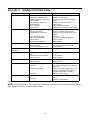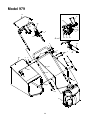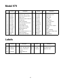
1
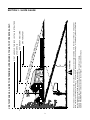
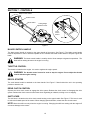
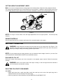
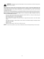
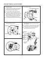
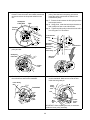
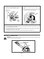
Operator’s Manual
21” Self-Propelled
Mower
Model No.
247.379790
Factory No.
12A-979L402
IMPORTANT: READ SAFETY RULES AND INSTRUCTIONS CAREFULLY
Warning: This unit is equipped with an internal combustion engine and should not be used on or near any unimproved forestcovered, brush-covered or grass-covered land unless the engine’s exhaust system is equipped with a spark arrester meeting
applicable local or state laws (if any). If a spark arrester is used, it should be maintained in effective working order by the operator.
In the State of California the above is required by law (Section 4442 of the California Public Resources Code). Other states may have
similar laws. Federal laws apply on federal lands. A spark arrester for the muffler is available through your nearest engine authorized
service dealer or contact the service department, P.O. Box 368022 Cleveland, Ohio 44136-9722.
MTD PRODUCTS INC. P.O. BOX 368022 CLEVELAND, OHIO 44136-9722
PRINTED IN U.S.A.
FORM NO. 770-10214
(12/98)
SECTION 1: FINDING YOUR MODEL NUMBER
This Operator’s Manual is an important part of your new walk behind. It will help you assemble, prepare and
maintain your walk behind. Please read and understand what it says.
Before you start to prepare your walk behind for its first use, please locate the model plate and copy the
information from it in this Operator’s Manual. The information on the model plate is very important if you need help
from your dealer or the MTD customer support department.
• Every walk behind has a model plate. You can locate it by standing behind the unit in the operating position
and looking down at the rear of the deck.
• The model plate will look like Figure 1.
This is where your model number will be.
XXX-X-XXX-X-XXX XXXXXXXXXXX
This is where your serial number will be.
Copy the model number here:
MTD PRODUCTS INC Copy the serial number here:
CLEVELAND, OHIO 44136
Figure 1
SECTION 2: CALLING CUSTOMER SUPPORT
• LOCATE YOUR MODEL NUMBER AND SERIAL NUMBER — Record this information in the space
provided. To find your unit’s specific model number and serial number, see SECTION 1: FINDING YOUR
MODEL NUMBER.
• If you are having difficulty assembling this product or if you have any questions regarding the controls,
operation or maintenance of this unit, please call the Customer Support Department.
• Customer Support can be reached by dialing: 1- (330) 220-4MTD
(4683)
or
1- (800)-800-7310
• Please have your model number and serial number ready when you call.
• Although both numbers are important, you will be asked to enter only your serial number before your call
can be processed.
2
3
D ON
NE,
REP
RES
ENT
WARNING
15°
DOT
TED
LI
ING
A
15°
SLO
PE
Do not mow on inclines with a slope in excess of 15 degrees (a rise of approximately 2-1/2 feet every 10 feet). A riding mower
could overturn and cause serious injury. If operating a walk-behind mower on such a slope, it is extremely difficult to maintain
your footing and you could slip, resulting in serious injury.
Operate RIDING mowers up and down slopes, never across the face of slopes.
Operate WALK-BEHIND mowers across the face of slopes, never up and down slopes.
FOL
OR A FENCE POST
A CORNER OF A BUILDING
A POWER POLE
SIGHT AND HOLD THIS LEVEL WITH A VERTICAL TREE
USE THIS PAGE AS A GUIDE TO DETERMINE SLOPES WHERE YOU MAY NOT OPERATE SAFELY.
SECTION 3: SLOPE GAUGE
SECTION 4: IMPORTANT SAFE OPERATION PRACTICES
WARNING: THIS SYMBOL POINTS OUT IMPORTANT SAFETY INSTRUCTIONS WHICH, IF NOT
FOLLOWED, COULD ENDANGER THE PERSONAL SAFETY AND/OR PROPERTY OF YOURSELF
AND OTHERS. READ AND FOLLOW ALL INSTRUCTIONS IN THIS MANUAL BEFORE ATTEMPTING
TO OPERATE YOUR LAWN MOWER. FAILURE TO COMPLY WITH THESE INSTRUCTIONS MAY
RESULT IN PERSONAL INJURY. WHEN YOU SEE THIS SYMBOL, HEED ITS WARNING.
DANGER: Your lawn mower was built to be operated according to the rules for safe operation in this
manual. As with any type of power equipment, carelessness or error on the part of the operator can
result in serious injury. This lawn mower is capable of amputating hands and feet and throwing objects.
Failure to observe the following safety instructions could result in serious injury or death.
1. GENERAL OPERATION
• Always wear safety glasses or safety goggles during
operation or while performing an adjustment or repair,
to protect eyes from foreign objects that may be
thrown from the machine in any direction.
• Read this owner’s guide carefully in its entirety before
attempting to assemble this machine. Read,
understand, and follow all instructions on the machine
and in the manual(s) before operation. Be completely
familiar with the controls and the proper use of this
machine before operating it. Keep this manual in a
safe place for future and regular reference and for
ordering replacement parts.
• Wear sturdy, rough-soled work shoes and close-fitting
slacks and shirts. Shirts and pants that cover the
arms and legs and steel-toed shoes are
recommended. Do not wear loose fitting clothes or
jewelry. They can be caught in moving parts. Never
operate a unit in bare feet, sandals, slippery or light
weight (e.g. canvas) shoes.
• Your rotary mower is a precision piece of power
equipment, not a plaything. Therefore, exercise
extreme caution at all times. Your unit has been
designed to perform one job: to mow grass. Do not
use it for any other purpose.
• Do not put hands or feet near or under rotating parts.
Keep clear of discharge opening at all times as the
rotating blade can cause injury.
• Never allow children under 14 years old to operate a
power mower. Children 14 years old and over should
only operate mower under close parental supervision.
Only responsible individuals who are familiar with
these rules of safe operation should be allowed to
use your mower.
• Many injuries occur as a result of the mower being
pulled over the foot during a fall. Do not hang on to
the mower if you are falling; release the handle
immediately.
• Never pull the mower toward you while you are
walking. If you must back the mower away from a wall
or obstruction first look down and behind, and then
follow these steps:
• Keep the area of operation clear of all persons,
particularly small children and pets. Stop engine
when they are in the vicinity of your mower to help
prevent blade contact or thrown object injury.
Although the area of operation should be completely
cleared of foreign objects, an object may have been
overlooked and could be accidentally thrown by the
mower in any direction and cause serious personal
injury to the operator or any others allowed in the
area.
• Step back from the mower to fully extend your arms.
• Be sure you are well balanced with sure footing.
• Pull the mower back slowly, no more than half way
toward you.
• Repeat these steps as needed.
• Do not operate the mower while under the influence
of alcohol or drugs.
• Thoroughly inspect the area where the equipment is
to be used. Remove all stones, sticks, wire, bones,
toys and other foreign objects which could be picked
up and thrown by the mower in any direction and
cause serious personal injury to the operator or any
others allowed in the area. Plan your mowing pattern
to avoid discharge of material toward roads,
sidewalks, bystanders and the like. To help avoid a
thrown objects injury, keep children, bystanders and
helpers at least 75 feet from the mower while it is in
operation.
• Do not engage the self-propelled mechanism on units
so equipped while starting engine.
• The blade control handle is a safety device. Never
attempt to bypass its operation. Doing so makes the
safety device inoperative and may result in personal
injury through contact with the rotating blade. The
blade control handle must operate easily in both
directions and automatically return to the disengaged
position when released.
4
• Never operate the mower in wet grass. Always be
sure of your footing. A slip and fall can cause serious
personal injury. Keep a firm hold on the handle and
walk, never run. If you feel you are losing your
footing, RELEASE THE BLADE CONTROL HANDLE
IMMEDIATLEY and the blade will stop rotating within
three seconds.
• Do not mow on wet grass. Reduced footing could
cause slipping.
3. CHILDREN
Tragic accidents can occur if the operator is not alert to the
presence of children. Children are often attracted to the
mower and the mowing activity. Never assume that children
will remain where you last saw them.
• Mow only in daylight or good artificial light.
• Keep children out of the mowing area and under the
watchful care of a responsible adult other than the
operator.
• Stop the blade when crossing gravel drives, walks or
roads.
• If the equipment should start to vibrate abnormally,
stop the engine and check immediately for the cause.
Vibration is generally a warning of trouble.
• Be alert and turn mower off if a child enters the area.
• Before and while moving backwards, look behind and
down for small children or other objects.
• Shut the engine off and wait until the blade comes to
a complete stop before removing the grass catcher or
unclogging the chute. The cutting blade continues to
rotate for a few seconds after the engine is shut off.
Never place any part of the body in the blade area
until you are sure the blade has stopped rotating.
• Never allow children under age 14 to operate the
mower. Children 14 years of age and above should
read and understand the operation instructions and
safety rules in this manual.
• Use extreme care when approaching blind corners,
shrubs, trees, or other objects that may obscure your
vision of a child or hazard.
• Never operate mower without proper guards, grass
catcher, plates or other safety protective devices in
place.
4. SERVICE
• Muffler and engine become hot and can cause a
burn. Do not touch.
• Use extreme care in handling gasoline and other
fuels. They are extremely flammable and the vapors
are explosive.
• Only use accessories approved for this machine by
the manufacturer. Read, understand, and follow all
instructions provided with the approved accessory.
• Use only an approved gasoline container.
• Never remove gas cap or add fuel while the engine is
running. Allow engine to cool at least two minutes
before refueling.
• If situations occur which are not covered in this
manual, use care and good judgment. Contact your
dealer for assistance. Telephone 1-800-800-7310 for
the name of your nearest dealer.
• Replace gasoline cap securely and wipe off any
spilled gasoline before starting the engine as it may
cause a fire or explosion.
2. SLOPE OPERATION
For your safety, use the slope gauge included as part of this
manual to measure slopes before operating this unit on a
sloped or hilly area. If the slope is greater than 15 degrees
as shown on the slope gauge, do not operate this unit on
that area or serious injury could result.
• Extinguish all cigarettes, cigars, pipes and other
sources of ignition.
• Never refuel machine indoors because flammable
vapors will accumulate in the area.
• Never store the machine or fuel container inside
where there is an open flame or spark such as a gas
water heater, space heater, or furnace.
DO:
• Mow across the face of slopes; never up and down.
Exercise extreme caution when changing direction on
slopes.
• Never run an engine inside a closed area.
• To reduce fire hazard, keep mower free of grass,
leaves, or other debris build-up. Clean up oil or fuel
spillage. Allow mower to cool at least 5 minutes
before storing.
• Watch for holes, ruts, hidden objects, or bumps. Tall
grass can hide obstacles.
• Always be sure of your footing. A slip and fall can
cause serious personal injury. If you feel you are
losing your balance release the blade control handle
immediately and the blade will stop in less than 3
seconds.
• Before cleaning, repairing, or inspecting, make
certain the blade and all moving parts have stopped.
Disconnect the spark plug wire, and keep the wire
away from the spark plug to prevent accidental
starting.
DO NOT:
• Check the blade and engine mounting bolts at
frequent intervals for proper tightness. Also, visually
inspect blade for damage (e.g., bent, cracked or
worn). Replace with blade which meets original
equipment specifications listed in this manual.
• Do not mow near drop-offs, ditches or embankments.
The operator could lose footing or balance.
• Do not mow slopes greater than 15 degrees as
shown on the slope gauge.
• Keep all nuts, bolts, and screws tight to be sure the
equipment is in safe working condition.
5
protection, frequently check components and replace
with manufacturer’s recommended parts, when
necessary.
• Never tamper with safety devices. Check their proper
operation regularly.
• After striking a foreign object, stop the engine,
remove the wire from the spark plug, and thoroughly
inspect the mower for any damage. Repair the
damage before starting and operating the mower.
• Mower blades are sharp and can cut. Wrap the
blade(s) or wear gloves, and use extra caution when
servicing them.
• Do not change the engine governor setting or
overspeed the engine. Excessive engine speeds are
dangerous.
• Never attempt to make a wheel or cutting height
adjustment while the engine is running.
• Grass catcher components are subject to wear,
damage and deterioration, which could expose
moving parts or allow objects to be thrown. For safety
• Do not adjust the throttle with the engine running.
WARNING: The engine exhaust from this product contains chemicals known to the
state of California to cause cancer, birth defects or other reproductive harm
WARNING - YOUR RESPONSIBILITY: Restrict
WARNING
0
527
the use of this
power machine to persons who read, understand and follow the warnings and instructions in
this manual and on the machine.
TO A
VOID
OWER
T
UNLE HE RISK OF INJURY, NEVER OPERATE M R
SS SIDE
O
CHUTE DEFLECTOR, MULCH PLUG
ENTIR
CE.
E GRASS
CATCHER IS IN ITS PROPER PLA
Figure 2 Safety Labels Found On Lawn Mower
6
SECTION 5: UNPACKING INSTRUCTIONS
REMOVE UNIT FROM CARTON
(See Figure 3.)
• Remove staples, break glue on top flaps, or cut tape at carton end and peel along top flap to open carton.
• Remove loose parts if included with unit (i.e., operator’s manual, etc.).
• Cut along dotted lines and lay carton down flat.
• Remove packing material.
• Roll or slide unit out of carton. Check carton thoroughly for loose parts.
REMOVE MANUAL & LOOSE PARTS
PUSH
Figure 3
DISCONNECT SPARK PLUG WIRE
Before setting up your lawn mower, disconnect the spark plug wire from the spark plug, and ground it against the
engine by attaching rubber boot to a bolt or metal clip to the grounding post on the engine. See Figure 4.
Spark Plug
Wire
Spark Plug
Figure 4
7
SECTION 6: SET-UP INSTRUCTIONS
ITEMS REQUIRED FOR ASSEMBLY
• Pair of Pliers (Not necessary, but helpful)
• Motor Oil (Included)
• Fresh Gasoline
IMPORTANT: This unit is shipped WITHOUT GASOLINE or OIL in the engine. Be certain to service engine
with gasoline and oil as instructed in the separate engine manual before operating your mower.
NOTE: Reference to right or left hand side of the mower is observed from the operating position.
SET UP YOUR LAWN MOWER
Follow steps 1 through 9 to set up your lawn mower.
Step 1. Remove grass bag from unit and set it out Step 2. Lift upper handle. Align it with lower
of the way.
handle.
Grass
Bag
Upper Handle
Step 3. Tighten wing nuts.
HERE
Step 4. Raise complete handle assembly until it
clicks into place. Make sure not to kink the
control cables.
Handle Assembly
K
CLIC
8
Step 5. Pinch lower handle against mounting
bracket with pliers.
Step 7. Attach control cables to handle with pull
ties found on the handle.
Step 6. Move hairpin clip from outer to inner hole
on left and right handle mounting brackets.
HERE
Inner Hole
Hairpin Clip
Pinch Here
Step 8. Squeeze the blade control handle against the upper handle and pull out the starter rope slowly.
Step 9. Thread the starter rope into the rope guide.
SQUEEZE
Blade Control Handle
Upper Handle
Rope Guide
Starter Rope
Look Here
9
SECTION 7: CONTROLS
Blade Control Handle
Throttle Control
Recoil Starter
Cutting Height
Adjustment Lever
Drive
Clutch
Control
Shift Lever
Figure 5
BLADE CONTROL HANDLE
The blade control handle is located on the upper handle of the mower. See Figure 5. The blade control handle
must be depressed in order to start and operate the unit. Release the blade control handle to stop the engine and
blade.
WARNING: The blade control handle is a safety device. Never attempt to bypass its operations. The
blade will be rotating whenever the engine is running.
THROTTLE CONTROL
The throttle is located on the engine. It is used to regulate the engine speed.
WARNING: The throttle control cannot be used to stop the engine. Do not adjust the throttle
control with the engine running.
RECOIL STARTER
The recoil starter handle is attached to the lower handle. See Figure 5. Stand behind the unit in the operating
position to start the unit.
DRIVE CLUTCH CONTROL
Squeeze the drive clutch control to engage the drive system. Release the clutch control to disengage the drive
system. Release the clutch control to slow down when negotiating an obstacle, making a turn or stopping.
SHIFT LEVER
The shift lever is located on the drive clutch control housing on the upper handle. See Figure 5. This lever is used
to select the forward speed of the mower. When changing speed selection, release the drive clutch control.
NOTE: Move the shift lever only when the engine is running. Changing the shift lever setting with the engine off
can cause damage to the mower.
10
CUTTING HEIGHT ADJUSTMENT LEVER
Note: Your mower is shipped with the cutting height in the lowest position. Adjust the cutting height as follows.
The cutting height adjustment lever is located above the left rear wheel. To adjust the cutting height, pull the lever
out and away from the mower and then move it forward or backward to select a new cutting height. See Figure 6.
LOWER
HIGHER
Cutting Height Adjustment Lever
Figure 6
NOTE: For rough or uneven lawns, move the height adjustment lever to a higher position. This will help stop
scalping.
ENGINE CONTROLS
See the engine manual for the location and function of the controls located on the engine.
SECTION 8: OPERATION
WARNING: Keep hands and feet away from the chute area on the cutting deck. See Figure 2. The
operation of any lawn mower can result in foreign objects being thrown into the eyes, which can result in
severe eye damage. Always wear safety glasses or eye shields.
NOTE: For best results raise the cutting position until it is determined which height is best for your lawn. See
CUTTING HEIGHT ADJUSTMENT LEVER in the CONTROLS section.
GAS AND OIL FILL-UP
Service the engine with gasoline and oil as instructed in the separate engine manual. Read all instructions
carefully.
WARNING: Never fill fuel tank indoors with engine running or until the engine has been allowed to
cool for at least two minutes after running.
EACH TIME YOU START YOUR MOWER
ALL UNITS:
• Attach spark plug wire to spark plug. Make certain the metal cap on the end of the spark plug wire is
fastened securely over the metal tip on the spark plug.
• Check for proper drive clutch operation using the NEUTRAL ADJUSTMENT TEST.
11
NEUTRAL ADJUSTMENT TEST
To perform the NEUTRAL ADJUSTMENT TEST answer the following questions.
• With the drive clutch control released, push mower forward and pull it backward. Does it move freely?
• Squeeze the drive clutch control and pull the mower backward. Do the rear wheels lock (not turn)?
• Is the drive clutch control cable free of kinks or sharp bends?
If you answered “yes” to all three questions, your mower passed the test and you can start your mower. If you
answered “no” to any of the three questions, you will have to adjust the drive clutch control following instructions
in the DRIVE CLUTCH CONTROL ADJUSTMENT section.
TO START ENGINE AND ENGAGE BLADE
• Move the throttle control on the engine to the fast (rabbit) position.
• Prime engine as instructed in the separate engine manual.
• Stand behind the unit, squeeze the blade control handle and hold it against the upper handle.
NOTE: If any problems are encountered, refer to the TROUBLE SHOOTING Section of this manual.
TO STOP ENGINE AND BLADE
• Release the blade control handle to stop the engine and the blade.
WARNING: The blade continues to rotate for a few seconds after the engine is shut off.
USING YOUR ROTARY MOWER
Be sure that the lawn is clear of stones, sticks, wire, or other objects which could damage the lawn mower or the
engine. Such objects could be accidently thrown by the mower in any direction and cause serious personal injury
to the operator and others.
For best results, do not cut wet grass because it tends to stick to the underside of the mower, preventing proper
discharge of grass clippings, and could cause you to slip and fall. New grass, thick grass or wet grass may require
a narrower cut.
For a healthier lawn, never cut off more than one-third of the total length of the grass. Your lawn should be cut in
the fall as long as there is growth.
This mower is designed to be operated at full throttle to give you the best cut and do the most effective job of
mowing or mulching.
WARNING: If you strike a foreign object, stop the engine. Remove wire from the spark plug,
thoroughly inspect the mower for any damage, and repair the damage before restarting and operating
the mower. Extensive vibration of the mower during operation is an indication of damage. The unit
should be promptly inspected and repaired.
12
BAGGING GRASS CLIPPINGS
This mower can bag grass clippings. Follow steps 1 through 3 to ready the mower for bagging.
Step 1. Remove wing nuts holding mulching baffle Step 2. Replace with bagging adapter. Attach
or side discharge chute in place. Then
using wing nuts. Be sure that inner lip of
remove plug or discharge chute.
attachment goes under the edge of the deck.
Step 3. Lift chute door and slide bag onto adapter.
Chute Door
NOTE: The chute door has been
designed to move the starter
rope out of the way of the bag
when the chute door is opened.
Bagging adaptor
Mulching baffle
Side-discharge chute
13
EMPTYING YOUR GRASS BAG
Holding the grass bag by both the rear handle and the lower handle, lift it straight up. The chute door will move
the rope out of the way of the bag. Remove the bag from the bagging adaptor on the mower. While holding the
lower handle lift up the rear section of the grass bag as shown in Figure 7. The bag will open and the grass
clippings will fall out. When replacing your grass bag be sure the top of the bag rests on the wire support between
the handles.
Grass
Clippings
Figure 7
SIDE-DISCHARGE GRASS CLIPPINGS
This mower can also side-discharge grass clippings. Follow steps 1 and 2 to ready this mower for side-discharge
operation.
Step 1. Remove mulching baffle or grass bag
adapter.
Step 2. Attach discharge chute with wing nuts.
14
SECTION 9: ADJUSTMENTS
WARNING: Do not at any time make any adjustment to lawn mower without first stopping engine and
disconnecting spark plug wire.
HANDLE HEIGHT ADJUSTMENT
Notch
Lower Handle
Figure 8
Your mower is shipped with the handle in the higher height position. To lower the height proceed as follows:
• Remove the starter rope from the rope guide.
• Remove the upper handle by removing the hand knobs and carriage bolts. Lay the upper handle out of the
way, being careful not to bend or kink the cables.
• Remove the hairpin clips from the weld pins on the handle brackets. Press out on the legs of the lower
handle. Remove lower handle from the mower.
• Turn lower handle around so the notch on the bottom of the lower handle is facing forward. See Figure 8.
Reassemble, placing the bottom holes in the handle over the weld pins in the handle mounting bracket.
• Reassemble the upper handle to the lower handle.
• Place the hairpin clips in the inner holes in the weld pins and attach the starter rope as instructed in the SetUp Instructions.
DRIVE CLUTCH CONTROL ADJUSTMENT
The drive clutch control adjustment wheel is located in the drive clutch control handle housing and is used to
tighten or loosen the drive belt. You will have to adjust the drive clutch control if any of the following happens:
• The mower does not propel itself with the drive clutch engaged.
• The mower’s drive wheels hesitate with the drive clutch engaged.
To resolve the above problems, rotate the adjustment wheel with your fingers. Clockwise to tighten the cable and
counter-clockwise to loosen the cable. See Figure 9.
Bottom View
Adjustment
Wheel
Figure 9
15
Note: For some people the drive clutch handle may not be in a comfortable position. You can adjust the handle
out by tightening the adjustment wheel.
SHIFT LEVER CABLE ADJUSTMENT
Periodic adjustment of the six speed shift cable may be required due to normal wear on the cable. Adjustment is
needed if all six speeds do not work.
The adjustable cable bracket is located on the left side of the mower, beside the engine. Follow steps 1 through 7
to adjust the shift lever.
Bottom View
Adjustable Cable Bracket
Hex Nut (A)
Speed Control
Lever
PUSH
Step 1. Start engine.
Step 2. Place speed control in the sixth speed
position.
Step 3. Stop engine.
Step 5. Loosen hex nut (A) which secures the
adjustable cable bracket.
Step 6. Push back on the adjustable cable bracket.
Step 7. Tighten hex nut (A).
Step 4. Disconnect spark plug wire and ground it.
16
SECTION 10: MAINTENANCE
WARNING: Be sure to disconnect and ground the spark plug wire before performing any repairs or
maintenance.
NOTE: When tipping the unit, empty the fuel tank and keep the engine spark plug side up. Never tip the mower
more than 90 degrees and do not leave the mower tipped for any length of time. Oil can drain into the upper part
of the engine causing a starting problem.
ENGINE
Refer to the separate engine manual for all engine maintenance instructions.
• Maintain engine oil as instructed in the separate engine manual packed with your unit. Read and follow
instructions carefully.
• Service air cleaner every 25 hours under normal conditions. Clean every few hours under extremely dusty
conditions. Poor engine performance and flooding usually indicate that the air cleaner should be serviced.
To service the air cleaner, refer to the separate engine manual packed with your unit.
• The spark plug should be cleaned and the gap reset once a season. Spark plug replacement is
recommended at the start of each mowing season; check engine manual for correct plug type and gap
specifications.
• Clean the engine regularly with a cloth or brush. Keep the cooling system (blower housing area) clean to
permit proper air circulation which is essential to engine performance and life. Be certain to remove all
grass, dirt and combustible debris from muffler area.
DECK
The underside of the mower deck should be cleaned after each use to prevent a buildup of grass clippings,
leaves, dirt or other matter. If this debris is allowed to accumulate, it will invite rust and corrosion, and may prevent
proper mulching, discharge or bagging.
The deck may be cleaned by tilting the mower and scraping clean with a suitable tool (make certain the spark plug
wire is disconnected).
CUTTING BLADE REMOVAL, REPLACEMENT AND SHARPENING
Blade
Adapter
Blade Bell
Support
Hex Bolt
Figure 10
• When removing the cutting blade for sharpening or replacement, protect your hands with a pair of heavy
gloves or use a heavy rag to hold the blade.
• Remove the bolt and the blade bell support which hold the blade and the blade adapter to the engine
crankshaft.
• Remove the blade and the adapter from the crankshaft.
17
WARNING: Periodically inspect the blade adapter for cracks, especially if you strike a foreign object.
Replace when necessary.
When sharpening the blade, follow the original angle of grind as a guide. It is extremely important that each
cutting edge receives an equal amount of grinding to prevent an unbalanced blade. An unbalanced blade will
cause excessive vibration when rotating at high speeds. It may cause damage to the mower, and could break
causing personal injury.
The blade can be tested by balancing it on a round shaft screwdriver. Remove metal from the heavy side until it
balances evenly. It is recommended that the blade always be removed from the adapter when testing for balance.
Before reinstalling the blade and the blade adapter to the unit, lubricate the engine crankshaft and the inner
surface of the blade adapter with light oil.
• Be sure to install the blade with the side of the blade marked “Bottom” (or with part number) facing the
ground when the mower is in the operating position.
• Slide the blade adapter on to the engine crankshaft.
• Place the blade on the adapter. Be certain the blade is aligned with and seated on the blade adapter
flanges.
• Place blade bell support on blade. Make sure the notches on the blade bell support are aligned with the
small holes in the blade.
• Replace hex bolt.
• Tighten hex bolt to torque: 450 in. lbs. min., 600 in. lbs. max.
NOTE: To ensure safe operation of your mower, the blade bolt must be checked periodically for correct torque.
18
DRIVE BELT REMOVAL AND REPLACEMENT
Step 1. Disconnect the spark plug wire and ground it
against the engine.
Step 9. Remove the hex bolt holding the transmission
to the mower housing.
Step 2. Drain the fuel tank or place a piece of plastic
beneath the cap to prevent gasoline leakage.
Rear Height Adjustment Lever
Step 3. Place shift lever in the first position.
Step 4. Tip the mower on its side. Block securely.
Step 5. Remove the center bolt which secures the
blade to the crankshaft. Remove the blade, and
the blade adapter, wave washer, and spacer.
Refer to Cutting Blade Removal, Replacement
and Sharpening in the Maintenance Section.
Step 6. Move rear height adjuster to the sixth position.
Hex Bolt
Baffle
Step 7. Using a 3/8” socket, remove three hex screws
holding the baffle to the deck.
Step 10. Tilt the transmission forward and loosen the
idler pulley bolt and lock nut 1/2 turn using two
7/16” wrenches.
Step 11. Using a pair of pliers, pull back and rotate belt
keeper bracket from the slot on the idler pulley.
Hex Screw
Step 12. Slide the belt out from between the belt
keeper bracket and the idler pulley.
Transmission
Pulley
Hex Screw
Hex
Screw
Belt
Belt Keeper
Bracket
Idler Pulley
Bracket
Step 8. Pivot baffle towards the rear of the mower.
Idler Pulley
Bolt and
Locknut
Baffle
19
Transmission
Step 13. Squeeze the belt together and push it
Step 16. Place the new belt over the transmission
forward. Press the control arm inward towards the
pulley. Start the belt in the pulley groove and
deck and remove the six speed cable from the
rotate the pulley until the belt is seated in the
slot.
transmission pulley.
Six-Speed
Cable Slot
Step 17. Place the belt between the idler pulley and the
belt keeper bracket.
Belt
Step 18. Using pliers, rotate the belt keeper bracket so
that it snaps into slot on the idler bracket.
Control
Arm
Step 19. Tighten the idler pulley bolt and lock nut half a
turn using two 7/16” wrenches.
Transmission
Pulley
Belt
Belt Keeper
Bracket
Transmission
Idler Pulley
Bracket
Step 14. Pivot the control arm down away from the
pulley and belt.
Idler Pulley
Six-Speed
Cable Slot
Bolt and
Locknut
Control
Arm
Step 15. Lift off the lower pulley assembly and remove Step 20. Place the belt between the two pulley halves
the old belt from around the crankshaft.
on the crankshaft. Make sure to route the belt
inside the belt guard pin.
Lower Pulley
Half
Upper
Pulley
Half
Crankshaft
Tab
Belt
Belt
Belt
Guard
Pin
Lower
Pulley
Half
IMPORTANT: When replacing the belt, do not disassemble the lower pulley assembly.
20
Step 21. Pinch both sides of the belt together so that
the belt is not in the pulley groove, and the lower
pulley can be pushed towards the engine.
Step 22. Pivot the control arm back to its original
position and reinstall the six-speed cable into the
slot.
Step 23. Check and make sure the belt is routed inside
the pulley halves and the belt guard pin.
Lower Pulley
Half
Belt
Belt
Guard
Pin
Step 24. Reinstall the bolt securing transmission to rear mower housing.
Step 25. Pivot the baffle back to its original position and secure with three hex screws earlier removed. You will
need a 3/8” socket for these screws.
Step 26. Lightly lubricate the inside of the blade adapter and reinstall the spacer, wave washer, blade adapter
assembly and the blade in the correct order.
Step 27. Tighten the hex bolt to secure the blade. Follow recommended torque: 450-600 in. lbs.
SECTION 11: LUBRICATION
WARNING: Always stop engine and disconnect spark plug wire before cleaning, lubricating or doing
any kind of service work on the lawn mower.
Blade Control Handle
LUBRICATE
Engine
SEE ENGINE MANUAL
Figure 11
21
Blade Control: Lubricate the pivot points on the blade control handle and the brake cable at least once a
season with light oil. See Figure 11. The blade control must operate freely in both directions.
Wheels: Lubricate the wheels at least once a season with light oil (or engine oil). Also, if the wheels are
removed for any reason, lubricate the surface of the axle bolt and the inner surface of the wheel with light oil. See
Figure 11.
Engine: Follow engine manual for lubrication instructions.
SECTION 12: OFF-SEASON STORAGE
The following steps should be taken to prepare your lawn mower for storage.
• Clean and lubricate mower thoroughly as described in the lubrication instructions.
• Refer to engine manual for correct engine storage instructions.
• Coat mower’s cutting blade with chassis grease to prevent rusting.
• Store mower in a dry, clean area. Do not store next to corrosive materials, such as fertilizer.
NOTE: When storing any type of power equipment in a poorly ventilated or metal storage shed, care should be
taken to rust-proof the equipment. Using a light oil or silicone, coat the equipment, especially cables and all
moving parts.
22
SECTION 13: TROUBLE SHOOTING GUIDE
Trouble
Possible Cause(s)
Corrective Action
Engine fails to start
Blade control handle disengaged.
Spark plug wire disconnected.
Throttle control lever not in correct
starting position.
Fuel tank empty, or stale fuel.
Blocked fuel line.
Faulty spark plug.
Engine flooded.
Engage blade control handle.
Connect wire to spark plug.
Move throttle lever to FAST or START
position.
Fill tank with clean, fresh gasoline.
Clean fuel line.
Clean, adjust gap or replace.
Crank engine with throttle in FAST position.
Engine runs erratic
Unit running in START position.
Spark plug wire loose.
Blocked fuel line or stale fuel.
Vent in gas cap plugged.
Water or dirt in fuel system.
Dirty air cleaner.
Carburetor out of adjustment.
Move throttle lever to FAST position.
Connect and tighten spark plug wire.
Clean fuel line; fill tank with clean, fresh
gasoline.
Clear vent.
Drain fuel tank. Refill with fresh fuel.
Clean air cleaner.
Adjust carburetor.
Engine oil level low.
Air flow restricted.
Carburetor not adjusted properly.
Fill crankcase with proper oil.
Remove blower housing and clean.
Adjust carburetor.
Engine overheats
Occasional skip (hesitates) at Spark plug gap too close.
high speed
Adjust gap to .030”.
Idles poorly
Spark plug fouled, faulty or gap too
wide.
Carburetor improperly adjusted.
Dirty air cleaner.
Reset gap to .030” or replace spark plug.
Excessive vibration
Cutting blade loose or unbalanced.
Bent cutting blade.
Tighten blade and adapter. Balance blade.
Replace blade.
Mower will not mulch grass
Engine speed too low.
Wet grass.
Set throttle between 3/4 and full throttle.
Do not mow when grass is wet; wait until
later to cut.
Mow once at a high cutting height, then
mow again at desired height or make a
narrower cutting swath (1/2 width).
Sharpen or replace blade.
Excessively high grass.
Dull blade.
Uneven cut
Wheels not positioned correctly.
Dull blade.
Adjust carburetor.
Clean air cleaner.
Place all four wheels in same height
position.
Sharpen or replace blade.
Refer to separate engine manual packed with your mower for more engine related information.
NOTE: For repairs beyond the minor adjustments listed above, contact your nearest authorized service dealer or
call 1-800-800-7310 for the Customer Support Center.
23
Model 979
24
Model 979
Ref.
No.
1
2
3
4
5
6
7
8
9
10
11
12
13
14
15
16
17
18
19
20
21
22
23
24
25
26
27
28
29
30
31
32
33
34
35
36
37
38
39
Part No.
710-0134
710-0654A
710-0703
712-0397
723-0233
736-0204
782-0046A-0665
710-0653
710-0969
731-1828
638-0012
682-0531
682-7526
682-7528
710-0653
710-0751
710-0896
710-1315
711-0835
713-0453
714-0474
720-0223
732-0803A
732-0832
736-0270
736-0369
738-0529
741-0324
741-0522
741-0978
748-0318
750-0151
750-0515
750-0807
750-1056
782-0568
682-3052A-0665
682-3053A-0665
710-1348
Ref.
No.
Description
Scr. Carr. 1/4-20 x .62
Scr. TT:3/8-18:1.00
Scr. 1/4-20 x .750
Wing Nut 1/4-20
Nut, Push .25 I.D. x .50 O.D.
Wash. Fl. .334 I.D.x .62 x.03
Deck - 21”
Scr. TT. 1/4-20 x .375
Scr. HL. 1/2-14 x .750
Baffle
Rear Axle Ass’y
Pivot Arm Ass’y
Trans. Axle Ass’y
Chain Cover Ass’y
Scr. TT 1/4-20 x .375
Cap Screw HH 1/4-20 x .620
Scr. AB 1/4-14 x .625
Scr. 3/8 116 x .25
Clevis Pin .50 Dia. x 4.82 Lg.
Chain-Endls. #48 .500P x 24L
Cotter Pin .125O.D. x .75
Grip
Spring Lever
Torsion Spring
Bell Wash. .285 x .75 x .082
Fl. Wash..508 I.D. 1.000 x.020
Nut Shld. .825 Dia. x .165 Lg.
Hx.Flg. Brg..506 I.D. x .590 L.
Hx.Flg. Brg. .506 I.D. x.715 L.
Hx. Slv. Brg..504 I.D. x .830 L.
Wheel Rachet
Spa. .550 I.D. x /750 O.D.
Spa. .51 .D. x .70 O.D. x 38 L.
Spa. .385 x .624 x .700
Shld. Spa. .385 I.D. X .715 Lg.
Brkt. - Ht. Adj. Spring
Handle Brkt. Ass’y. R.H.
Handle Brkt. Ass’y. L.H.
Scr. AB 1/4-14 x .500
25
40
41
42
43
44
45
46
47
48
49
50
51
52
53
54
55
56
58
59
60
61
64
65
66
67
68
69
70
72
73
74
75
76
77
78
79
80
Part No.
731-1901
732-0842
611-0064-0665
710-1241
710-1242
714-0104
731-1829
736-0286
741-0492A
782-0565-0665
734-1978
734-1981
736-0105
736-0504
738-0102
10622B
748-0381
748-0188B
16855
738-0137A
712-0414
731-1426
725-0157
710-0604
754-0460
742-0741
753-0609
736-0524A
710-1257
735-0639
731-1832
731-1833
631-0066
731-1713A
747-0965
732-0819
726-0111
731-1874
Description
Trail Shield
Trail Shield Wire
Fr. Axle Ass’y.
Hx Scr. Wash Hd. Hi.-Lo.
Scr. Torx, Truss Hi.-Lo.
Cotter Pin .072 x 1.12 Lg.
Fr. Axle Cover, Yellow
Bowed Washer
Bush. Block .505 Dia. x .62
Control Arm
Wheel 8 x 2 Link, Yellow
Wheel 9 x 2 Link Yellow, Slv.
Spr. Wash. .401 x .870 x .063
Wave Wash .510 x .750 x .017
Shld. Scr .498 x 1.445 x3/8-16
Spring, Ratchet, Plastic
Pawl - R.H.
Pawl - L.H. (Not Illustrated)
Ratchet Pawl Plate
Scr. Shld. .340 x .285
Top Lock Tab Weld Nut 1/4-20
Hubcap -Yellow
Cable Tie
Hex Scr. 5/16-18
V-Belt
21” Mulching Blade
Blade Adapter Kit
Blade Bell Suport
Hex Bolt 3/8-24x2.5”Lg.
Spark Plug Insulator
Side Discharge Chute
Mulch Cover
Chute Ass’y
Discharge Chute
Pivot Rod
Torsion Spring
Push Cap
Chute Door
Model 979
27
16
28
24
29
21
18
20
23
A
13
8
11
19
A
17
22
3
26
5
6
37
1
36
3
4
25
5
15
34
33
35
14
30
2
32
2
31
26
Model 979
Ref.
No.
1
2
3
4
5
6
8
11
13
14
16
17
18
19
20
21
Part No.
Code
710-1174
714-0104
720-0241
726-0240
736-0451
712-0429
710-1270
712-0324
746-0883
746-0912
731-0904A
731-0924
713-0397
710-1667
732-0627
16864
Description
Ref.
No.
Bolt Cur. Carr. 5/16-18 x 2.0
Cotter Pin .072 x 1.12 Lg.
Knob Ass’y Wingnut 5/16-18
Strap 4.3 Lg.
Wash. Sad. .320 ID x.830 OD
Hex Nut 5/16
Oval C-Sunk Screw
Nut 1/4-20 Top locknut Insert
Control Housing
Control Cable 47” Lg.
Upper Control Housing
6 Speed Shift Lever
Gear Insert
C Sunk Tap Screw #10 x .75 L
Shift Lever Spring
6 Spd. Rack Cable Brkt.
22
23
24
25
26
27
28
29
30
31
32
33
34
35
36
37
Part No.
Code
731-0905A
731-0906
731-0620
746-0939
746-0713
747-0824
720-0294
749-0439C
749-0907A
631-0071
747-0939
726-0106
747-0937
747-0940A
664-0074
736-0451
Description
Lower Control Housing
Cable Mounting Cap
Control Lever
6 Spd. Cable
S.P. Cable
Control Handle
Foam Grip (2 Reqd.)
Upper Handle
Lower Handle
Grassbag Cover w/Label
Pivot Rod
Cap Nut
Frame - Grassbag
Rod, Support w/ Rope Guide
Grassbag
Saddle Washer
Labels
Ref
No.
Part No.
N/I
N/I
N/I
777S30116
777S30118
777S30128
N/I
777D01180
Code
Ref
No.
Description
Danger - Rt. Rear
Danger - Side Discharge
Warning - Above Deck
Opening
Mulches, Bags, Discharge
N/I
N/I
N/I
27
Part No.
777D00535
777I20291
777D01301
Code
Description
Wheel Cover Label
Ht. Adjuster Label
Model No. Label
Model 979
8
6
1
15
3
19
13
2
9
16
14
12
11
10
4
18
17
7
5
Ref.
No.
Part No.
1
2
3
4
5
6
7
8
9
10
11
12
13
14
15
16
17
18
19
746-0939
656-0613
710-0167
710-0896
711-1114
712-0287
732-0807
736-0270
736-0329
736-0526
738-0924
750-1070
750-1071
756-0625
782-7574-0665
782-7575-0665
782-7596
782-7597
712-0138
Code
Description
6 Spd. Cable
Pulley Ass’y Multi- Spd.
Scr. 1/4-20 x .50 Carr.
Scr. AB 1/4-14 x .625 Hxinwsh
Pivot Shaft
Nut 1/4-20
Torsion Spring LH
Bell Wash. .265 X .75 X .062
Lock Wash. 1/4 Reg Duty
Wave Wash. 1.38 x .88 x .029
Shld.Scr. .375 x1/4-14AB
Slev Spcr .88 IDx1.00 OD x.48
Slev Spcr .88ID x1.13ID x .12
Roller Cable
6 Spd. Cable Adj. Bracket
6 Spd. Cable Mt. Bracket
6 Sp. Control Arm
6 Sp. Pivot Bracket
Hex Nut 1/4-28
28
Model 979
Ref.
No.
29
Part No.
Code
1
712-3025
2
736-0425
3
4
756-0656
736-3084
5
712-0896
6
7
8
9
782-7598
741-0600
750-1050
682-0027A
10
710-0299
11
12
13
732-0849A
741-0682A
736-0570
14
15
721-0329
618-0253
16
736-0616
N
17
717-1487
N
18
736-0314
19
736-0569
20
618-0252
21
710-0642
22
23
24
25
26
27
782-7601A
741-0674
611-0066
721-0325
717-1469
711-1168
28
29
30
31
32
741-0672
721-0329
782-7595
741-0324
736-0369
33
741-0690
N
N
N
N
Description
Hx. Jam Nut
5/16-24
Bell Wash. .325
x .930 x .045
Pulley
Fl. Wash. .510 x
1.120 x .060
Hx. Jam Nut
1/4-28
Belt Keeper
Bearing
Flange Spacer
Idler Bracket
Assembly
Hx. Cap Scr. 1/428 x 1.00 Gr. 5
Extension Spring
Bearing Sleeve
Fl. Wash. .885 x
1.145 x.030
Oil Seal
Upper Housing
Assembly
Thrust Wash.
.504 x .700 x
.030
Pinion Shaft
10 T.
Thr. Wash. 3/8 x
.70 x .030
Thr. Wash. .388
x .625 x .062
Lower Housing
Assembly
Hx. Scr. 1/2-20 x
.75
Cable Bracket
Bearing
Shaft Assembly
Plug
Gear 34 T.
Output Shaft
6 T.
Flange Bearing
Oil Seal
Pivot Bracket
Flange Bearing
Wash. Fl. .508
I.D. x 1.00 O.D. x
.020
Bearing
30
MANUFACTURER’S LIMITED WARRANTY FOR:
For TWO YEARS from the date of retail purchase within the United States of America, its possessions and
territories, MTD Products will, at its option, repair or replace, for the original purchaser, free of charge, any part or
parts found to be defective in material or workmanship. This warranty covers units which have been operated and
maintained in accordance with the owner’s instructions furnished with the unit, and which have not been subject to
misuse, abuse, commercial use, neglect, accident, improper maintenance or alteration.
Normal wear parts or components thereof are subject to separate terms as noted below in the “No Fault Ninety
Day Consumer Warranty” clause.
All normal wear part failures will be covered on this product for a period of 90 days regardless of cause. After 90
days, but within the two year period, normal wear parts failures will be covered ONLY IF caused by defects in
material or workmanship of OTHER component parts. Normal wear parts are defined as batteries*, belts, blades,
blade adapters, grass bags, rider deck wheels, seats, snow thrower skid shoes, shave plates and tires.
How to obtain service: Warranty service is available, with proof of purchase, through your local authorized
service dealer. To locate the dealer in your area, please check the yellow pages or contact the Customer Service
Department of MTD Products, P O Box 368022, Cleveland, Ohio 44136-9722.
Phone 1 (800) 800-7310. The return of a complete unit will not be accepted by the factory unless prior written
permission has been extended by the Customer Service Department of MTD Products.
Transportation charges: Transportation charges for the movement of any power equipment unit or attachment
are the responsibility of the purchaser.
Units exported out of the United States: MTD Products does not extend any warranty for products sold or
exported outside of the United States of America, its possessions and territories, except those sold through MTD
Products’ authorized channels of export distribution.
Other Warranties:
1. The engine or component parts thereof carry separate warranties from their manufacturers. Please refer to
the applicable manufacturer’s warranty on these items.
2.
*Batteries are covered by a 90-day replacement warranty.
3.
Log splitter pumps, valves and cylinders or component parts thereof are covered by a one year warranty.
4.
All other warranties, express or implied, including any implied warranty of merchantability or fitness for a
particular purpose, are hereby expressly disclaimed in their entirety.
5.
The provisions as set forth in this warranty provide the sole and exclusive remedy of MTD Products’
obligations arising from the sales of its products. MTD Products will not be liable for incidental or
consequential loss or damage.
How state law relates to this warranty: This limited warranty gives you specific legal rights, and you may also
have other rights which vary from state to state. Certain disclaimers are not allowed in some states and therefore
these may not apply to you under all circumstances.
Note: This warranty does not cover routine maintenance items such as lubricants, filters, blade sharpening and
tune-ups, or adjustments such as brake adjustments, clutch adjustments or deck adjustments. Nor does this
warranty cover normal deterioration of the exterior finish due to use or exposure.