1
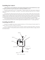
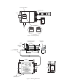
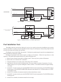
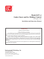
®
We manage heat ®
Model GIT–4
Gutter Snow and Ice Melting Control
Part Number 19556
Installation and Operation Manual
WARNING
Hazard of electrical shock.
Follow all safety procedures.
Any installation involving electric heater wiring must be grounded to earth to protect against shock
and fire hazard. Suitable ground fault detection and interrupting systems must be in use at all times to
reduce shock and fire hazard and to protect equipment.
Electric wiring to heating elements must be installed in accordance with Article 110.3B,
Article 210.8(A)(3), Article 250.4(A), Article 426.4 & 28, Article 725.55 and all other applicable
sections of the National Electric Code (NFPA 70), local electrical codes, and any third party
standards.
Only qualified personnel trained in electrical equipment service should perform maintenance on
heating and control equipment.
Environmental Technology, Inc.
1850 N Sheridan Street
South Bend, Indiana 46628
(574) 233-1202 or (800) 234-4239
FAX (574) 233-2152 or (888) 234 4238
www.networketi.com
DISCLAIMER
Environmental Technology, Inc. makes no representations or warranties, either expressed or implied, with
respect to the contents of this publication or the products that it describes, and specifically disclaims any
implied warranties of merchantability or fitness for any particular purpose. Environmental Technology,
Inc. reserves the right to revise this publication and to make changes and improvements to the products
described in this publication without the obligation of Environmental Technology, Inc. to notify any person
or organization of such revisions, changes or improvements.
Copyright © 2008 Environmental Technology, Inc. All rights reserved. No part of this manual may be reproduced or translated in any form or by any means, electronic or mechanical including photocopying and recording, for any purpose without
the express written consent of Environmental Technology, Inc.
The ETI logo and We Manage Heat are registered trademarks of Environmental Technology, Inc.
GIT is a trademark of Environmental Technology, Inc.
Printed in USA
PN19592 rev G 11/2009
Description
The computerized UL and CUL Listed GIT–4 automatically controls gutter and downspout snow and ice melting
heaters. It is safety tested to Standard 873 for Temperature Indicating and Regulating Equipment. The GIT–4 includes
the GFEP (ground fault equipment protection) required by the NEC.
The GIT–4 consists of sensor and control assemblies connected by a 12' (3.6 m) cable. The sensor meets the
NEC (National Electrical Code) low voltage Class 2 requirement for wet locations.
The GIT–4 requires an RCU–2 Remote Control Unit which is included. The RCU–2 provides remote control
and monitoring of the GFEP function. It also permits operating the snow and ice melting heaters for a fixed time at
temperatures below 38˚ F (3.3˚ C).
Supply Voltage Options
The GIT–4 provides jumper-selected supply voltage options of 120, 208 through 240, and 277 volts. Selecting
the proper supply voltage is very important. An incorrect setting may destroy the GIT–4 or render it inoperative.
The GIT–4 operates from the heater supply voltage.
Relay (Contactor) Contact Ratings
The relay (contactor) provides a Form A (SPST) contact rated for up to 26 amp AC heater loads at voltages at
or below 277 volts.
Safety
Any installation involving electric heater wiring must be grounded to earth to protect against shock and fire
hazard. Suitable ground fault detection and interrupting systems must be in use at all times to reduce shock and fire
hazard and to protect equipment.
Electric wiring to heating elements must be installed in accordance with Article 110.3B, Article 210.8(A)(3),
Article 250.4(A), Article 426.4 & 28, Article 725.55 and all other applicable sections of the National Electric
Code (NFPA 70), local electrical codes, and any third party standards. Follow the installation instructions
contained herein and those provided by the heater manufacturer. If you have questions concerning the installation
contact Customer Service for assistance.
The use of a GIT–4 with integral GFEP satisfies the NEC requirement for GFEP on each branch circuit
connected to the snow and ice melting system. Clearly label each circuit breaker with its function. This is vitally
important when there is more than one point of disconnect.
Make certain that the heater shield is properly grounded as required by the NEC.
Installing the Sensor
Mount the sensor as low as possible in the gutter about a foot upstream of the downspout. For proper operation,
the heating cable must be close to but not touching the sensor. A separation of 1/2" (1.3 cm) to 1" (2.5 cm) is ideal.
Orient the sensor with the temperature sensor facing upstream and the moisture sensor toward the down spout. Use
the supplied plastic mounting straps and gasketed #10 fasteners to secure the sensor in the gutter via 3/16" drilled
holes through the gutter. See Figure 1.
Installing the Control
Lethal voltages are present within the control enclosure during operation. Some installations may require
two points of disconnect. Tag all circuit breakers off during installation or service.
The GIT–4 comes factory set for 277 volt operation. A jumper located in the control must be changed for
120 or 208 through 240 volt operation. See Figure 2. An incorrect setting may destroy the GIT–4 or render it
inoperative.
The control comes connected to the sensor with 12 feet (3.6 meter) of three conductor cable. The snow and ice
melting heater leads, supply leads and sensor leads terminate in the control enclosure. Locate the control enclosure
outdoors at a place convenient for the wiring connections. Position the control housing so that the sensor cable entry
is positioned at the right of the housing, heater leads exit to the left and the supply leads enter at the bottom. Failing
to orient the housing correctly may cause moisture collection in the housing resulting in equipment damage.
For line supply and load connections use #10 AWG or larger wires rated for at least 194° F (90° C). Figures 4 and
5 show wiring for typical 120/240 volt residential applications and unbalanced 208 or 277 3-phase applications.
Installing the RCU–2
The RCU–2 is an NEC Class 2 device. It can be located up to 150 feet (46 meters) from the control. Use
customer supplied #18 AWG 2-conductor jacketed cable.
Choose a convenient protected indoor location. The RCU–2 mounts in a single gang switch box. The wiring
connections to the RCU–2 are not polarity sensitive and connect to the two blue wires in the low voltage section of
the control enclosure.
Jam Nut
Nut
Sensor
Gutter
Nylon Clamp
Drill 3/16" Hole
2 Places
O-ring
Screw
Figure 1. Sensor mounting
277V Connection Shown
12' Jacketed Cable
Environmental Techno
South Bend, Indiana
South
Conduit
NAME
120V 208/240V
277V
RCU-2
Line / Line 1
Neutral / Line 2
Equipment Ground
®
120V 208/240V
277V
120V 208/240V
120V
Connection
277V
208V thru 240V
Connection
Figure 2. Selecting Voltage
Removable Mounting Clamp
Clearance for #10 Screw
Heated Moisture
Sensing Grid
.81"
(20.6mm)
Ambient Air
Temperature
Sensor
1.12"
(28.5mm)
12' (3.6m) Jacketed
3 Conductor #18 AWG Cable
5.56"
(141.2mm)
1.50"
(38.1mm)
7 7/16"
(189mm)
2.75"
(69.9mm)
RCU-2
4
1/ "
4
(108mm)
4.50"
(114.3mm)
®
ENVIRONMENT
ALTECHNOL
OGY, INC.
SOUTHBEND, INDIANAU.S.A.
RCU– 2
3/4"(21mm)
Conduit Entry
Figure 3. Mounting Dimensions
GIT-4 CONTROL
HEATER
YELLOW
BLACK
LINE / LINE 1
120 / 240 VOLT SUPPLY
(GFEP PROTECTED)
HIGH
ELECTRONICS
NEUTRAL / LINE 2
WHITE
SAFETY GROUND
GREEN
YELLOW
GREEN
RETURN
RED
SHIELD
WHITE
BLUE
RCU-2
GIT-4 SENSOR
BLACK
BLUE
Figure 4. Typical 120/220 Volt Residential Applications
208 / 277
GI T- 4 CONTROL
BLACK
208 OR 277 VO LT 3-PHASE SUPPL Y
(GFEP PROTECTED)
YELLOW
HIGH
HEA TER
ELECTRONICS
208 / NEUTRAL
SAFETY
WHITE
GROUND
YELLOW
GREEN
GREEN
RETURN
RED
RCU-2
BLUE
WHITE
BLUE
BLACK
SHIELD
GI T- 4 SENSOR
Figure 5. Unbalanced 208 or 277 3-Phase Applications
Post Installation Tests
Thoroughly check the system before placing it in service. Our experience shows that installation errors cause the
majority of problems. Frequently encountered problems include wiring errors and improper waterproofing. Simple electrical
tests and visual inspections identify these problems.
Checking the sensor in the field is not practical. Verifying its operation requires special test equipment that is
neither portable nor commonly available.
Checking the operation of the control requires a clamp-on AC ammeter. Follow the steps below to verify
operation. The gutter and downspout must be dry while doing these tests.
1. Remove power from the snow and ice melting system. There may be two points of disconnect.
2. Remove the cover from the GIT–4 controller.
3. Clamp the ammeter to one of the yellow leads in the GIT–4 controller.
4. Apply power to the snow and ice melting system. This may require two points of connection. Use care.
Lethal voltages are now present withing the control enclosure. The ammeter should read approximately
zero amps.
5. At the RCU–2 remote control, press the HEATER TOGGLE switch momentarily. The HEATER indicator
should operate. If the SUPPLY and HEATER indicators flash alternatively, a GFEP condition or a GFEP
circuit failure exists.
6. At the GIT–4 controller, the ammeter should read the nominal heater current.
7. At the RCU–2 remote control, press the HEATER TOGGLE switch momentarily. The HEATER indicator
should turn off.
8. At the GIT–4 controller, the ammeter should read zero amps.
9. Remove the ammeter from the GIT–4 controller.
10. Replace the cover on the GIT–4 controller.
11. Apply power to the snow and ice melting system. This may require two points of connection.
Checking the system function requires moisture and a cold source. If the temperature is already below 38°F
(3.3°C) then simplying appling a small amount of moisture (such as a damp, clean paper towel) should energize the
heaters. If the temperature is above 38°F (3.3°C) then the temperature probe needs to be brought down below 38°F
(3.3°C) using freeze spray or crushed ice before appling a small amount of moisture (such as a damp, clean paper
towel).
Operating Instructions
The GIT–4 does not require user intervention during normal operation. The green SUPPLY indicator operates
to show that power is applied to the system. The yellow HEATER indicator operates while the heaters are operating
or enabled to operate.
In some installations drifting and blowing snow may present a problem if this does not occur at the sensor. In
this case, press the HEATER CYCLE switch to energize the heaters for one hour to melt accumulated snow. Repeat
as required after each one hour period until accumulated snow and ice are melted.
Semi-monthly Routine Testing
Press the TEST/RESET switch to test the GIT–4 GFEP for proper functioning. The SUPPLY and HEATER
indicators flash alternately for a few seconds during testing. The RCU–2 flashes these indicators if the test fails.
Pressing the TEST/RESET switch will not clear this condition. If the test fails, the GIT–4 will not operate the snow
and ice melting system heaters. You need to have a qualified electrician fix the problem.
If the snow and ice melting system is operating normally, there is no need for this test. Press the HEATER
TOGGLE switch momentarily. The HEATER indicator should operate. After a few seconds, press the HEATER
TOGGLE switch again. The HEATER indicator should turn off. If the SUPPLY and HEATER indicator flash
alternately, a GFEP failure exists. You need to have a qualified electrician fix the problem.
Maintenance
Although the GIT–4 does not require routine maintenance, make certain that the gutters and down spouts are
cleaned each fall to ensure efficient gutter and down spout snow and ice melting system efficiency.
For technical help, questions or comments concerning this product or any Environmental Technology, Inc.
products contact the Customer Service Department between 8:00am and 5:00pm EST (UTC minus five hours) at:
Voice:
800.234.4239 (USA and Canada) or 574.233.1202 (elsewhere)
Fax:
888.234.4238 (USA and Canada) or 574.233.2152 (elsewhere)
E-mail: [email protected]