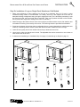
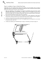
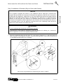
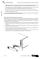
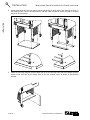
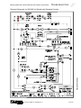
1
OPERATOR’S MANUAL
Marathoner Gold & SilverStar
GAS CONVECTION OVENS
SilverStar Models
SLGB/12CCH
SLGB/12SC
SLGB/15CCH
SLGB/15SC
SLGB/22CCH
SLGB/22SC
SLGB/25CCH
SLGB/25SC
MANUAL 1181887 REV 1
$18.00
SLGS/12CCH
SLGS/12SC
SLGS/15CCH
SLGS/15SC
SLGS/22CCH
SLGS/22SC
SLGS/25CCH
SLGS/25SC
Marathoner Gold Models
GB/12CCH
GB/12PC
GB/12RT
GB/12SC
GB/15CCH
GB/15PC
GB/15RT
GB/15SC
GB/22CCH
GB/22PC
GB/22RT
GB/22SC
GB/25CCH
GB/25PC
GB/25RT
GB/25SC
GS/12CCH
GS/12PC
GS/12RT
GS/12SC
GS/15CCH
GS/15PC
GS/15RT
GS/15SC
GS/22CCH
GS/22PC
GS/22RT
GS/22SC
GS/25CCH
GS/25PC
GS/25RT
GS/25SC
GAS CONVECTION OVENS
MANUAL SECTION CO
MARATHONER GOLD & SILVERSTAR GAS CONVECTION OVENS
SAFETY PRECAUTIONS
Before installing and operating this equipment, be sure everyone involved in its operation is fully trained
and aware of precautions. Accidents and problems can be caused by failure to follow fundamental rules
and precautions.
The following symbols, found throughout this manual, alert you to potentially dangerous conditions to the
operator, service personnel, or to the equipment.
! DANGER
This symbol warns of immediate hazards which will result in severe injury or
death.
! WARNING
This symbol refers to a potential hazard or unsafe practice which could result in
injury or death.
! CAUTION
This symbol refers to a potential hazard or unsafe practice which could result in
injury, product damage, or property damage.
NOTICE
This symbol refers to information that needs special attention or must be fully
understood, even though not dangerous.
! WARNING
FIRE HAZARD
FOR YOUR SAFETY
Do not store or use gasoline or other flammable vapors and liquids in the vicinity of this or any other
appliance.
Keep area around appliances free and clear of combustibles.
Purchaser of equipment must post in a prominent location detailed instructions to be followed in the
event the operator smells gas. Obtain the instructions from the local gas supplier.
! WARNING
Asphyxiation can result from improper ventilation. Do not obstruct the flow of combustion and
ventilation air to and from your cooking equipment.
NOTICE
Be sure this Operator’s Manual and important papers are given to the proper authority to retain for
future reference.
NOTICE
This product is intended for commercial use only. NOT FOR HOUSEHOLD USE.
PAGE 2
OPERATOR’S MANUAL 1181887 REV 1
MARATHONER GOLD & SILVERSTAR GAS CONVECTION OVENS
OPERATOR’S MANUAL 1181887 REV 1
TABLE OF CONTENTS
PAGE 3
SPECIFICATIONS
PAGE 4
MARATHONER GOLD & SILVERSTAR GAS CONVECTION OVENS
OPERATOR’S MANUAL 1181887 REV 1
SPECIFICATIONS
MARATHONER GOLD & SILVERSTAR GAS CONVECTION OVENS
The serial plate is located inside the lower front panel. It indicates the type of gas the unit is equipped to
burn. All Southbend equipment is adjusted at the factory. Check type of gas on serial plate.
These models are design-certified for operation on natural or propane gases. For natural gas, the regulator
is set to deliver a 4.5" W.C. pressure to the manifold. For propane gas, it is set to deliver 11" W.C.
If applicable, the vent line from the gas appliance pressure regulator shall be installed to the outdoors in
accordance with local codes, or in the absence of local codes, with the National Fuel Gas Code, ANSI
Z223.1, Natural Gas Installation Code, CAN/CGA-B149.1, or the Propane Installation Code CAN/CGAB149.2, as applicable.
This appliance should be connected ONLY to the type of gas for which it is equipped.
A 3/4" NPT line is provided at the rear for the gas connection. An adequate gas supply is imperative.
Undersized or low pressure lines will restrict the volume of gas required for satisfactory performance.
Fluctuations of more than 25% on natural gas or 10% on propane gas will create problems and affect
burner operating characteristics.
An adequate gas supply line to the unit should be no smaller than the inside diameter of the pipe from the
unit to which it is connected.
Purge the supply line to clean out dust, dirt, or other foreign matter before connecting the line to the unit.
All pipe joints and connections must be tested thoroughly for gas leaks. Use only soapy water for testing on
all gases. NEVER use an open flame to check for gas leaks. All connections must be checked for leaks
after the unit has been put into operation. Test pressure should not exceed 1/4" W.C.
Model Number
GS/12…
SLGS/12…
GS/15…
SLGS/15…
GB/12…
SLGB/12…
GB/15…
SLGB/15…
GS/22…
SLGS/22…
GS/25…
SLGS/25…
GB/22…
SLGB/22…
GB/25…
SLGB/25…
# of Ovens
Oven Depth
Type of Gas
Orifice Size
# of Burners
Total BTU
Single-Deck
Shallow
Propane
55
3 @ 18,000 BTU
54,000
Single-Deck
Shallow
Natural Gas
47
4 @ 18,000 BTU
72,000
Single-Deck
Bakery
Propane
55
4 @ 18,000 BTU
72,000
Single-Deck
Bakery
Natural Gas
47
5 @ 18,000 BTU
90,000
Double-Deck
Shallow
Propane
55
6 @ 18,000 BTU
108,000
Double-Deck
Shallow
Natural Gas
47
8 @ 18,000 BTU
144,000
Double-Deck
Bakery
Propane
55
8 @ 18,000 BTU
144,000
Double-Deck
Bakery
Natural Gas
47
10 @ 18,000 BTU
180,000
OPERATOR’S MANUAL 1181887 REV 1
PAGE 5
SPECIFICATIONS
GAS SUPPLY
SPECIFICATIONS
SPECIFICATIONS
MARATHONER GOLD & SILVERSTAR GAS CONVECTION OVENS
EXTERIOR DIMENSIONS
Single-Deck Ovens
A
B
8"
18.625"
2.5"
4"
38"
13.5"
2.5"
1.25"
C
TOP VIEW
29"
57.5"
55"
42.875"
33"
29.25"
26"
SIDE VIEW
Model
Number
Depth Dimensions
FRONT VIEW
Oven Interior
Rack Clearance
Shipping Crate
A
B
C
width
depth
height
width
depth
width
depth
height
volume
weight
GS/1…
SLGS/1…
38.5"
30"
34.375"
29"
22.5"
20"
28.25"
22"
55"
45.5"
45"
65.17 cu. ft.
620 lbs.
GB1…
SLGB/1…
45"
36.375"
40.75"
29"
28"
20"
28.25"
27.25"
55"
45.5"
45"
65.17 cu. ft.
690 lbs.
PAGE 6
OPERATOR’S MANUAL 1181887 REV 1
SPECIFICATIONS
MARATHONER GOLD & SILVERSTAR GAS CONVECTION OVENS
SPECIFICATIONS
Double-Deck Ovens
A
B
8"
18.625"
2.5"
4"
38"
13.5"
2.5"
1.25"
C
TOP VIEW
29"
66.5"
64"
38.25"
29"
42"
22.875"
13"
9.5"
6"
SIDE VIEW
Model
Number
Depth Dimensions
FRONT VIEW
Oven Interior
Rack Clearance
Shipping Crate
A
B
C
width
depth
height
width
depth
width
depth
height
volume
weight
GS/2…
SLGS/2…
38.75"
30"
34.375"
29"
22.5"
20"
28.25"
22"
55"
45.5"
81.5"
118 cu. ft.
1040 lbs.
GS/2…
SLGS/2…
45.125"
36.375"
40.75"
29"
29"
20"
28.25"
27.25"
55"
45.5"
81.5"
118 cu. ft.
1080 lbs.
OPERATOR’S MANUAL 1181887 REV 1
PAGE 7
SPECIFICATIONS
SPECIFICATIONS
MARATHONER GOLD & SILVERSTAR GAS CONVECTION OVENS
MINIMUM CLEARANCES
! WARNING
There must be adequate clearance between the left side of the ovens and combustible construction.
Minimum Clearance from
Minimum Clearance from
Combustible Construction
Non-Combustible Construction
Back
0"
0"
Right Side
0"
0"
Left Side
2"
0"
Floor
0"
0"
Adequate clearance must be provided in the aisle to allow the doors to open sufficiently to permit the
removal of the racks and for serviceability.
Although no clearance is required behind the motor on the rear of the oven, care must be taken to
provide adequate air circulation to prevent the motor from overheating.
Do not locate the oven adjacent to any high heat or grease-producing piece of equipment, such as a
range top, griddle, fryer, etc., that could allow radiant heat to raise the exterior temperature of the oven
above 130°F (54°C). DO NOT MOUNT ABOVE OTHER COOKING EQUIPMENT.
VENTILATION
! WARNING
Improper ventilation can result in personal injury or death. Ventilation which fails to properly remove
flue products can cause headaches, drowsiness, nausea, or could result in death.
All units must be installed in such a manner that the flow of combustion and ventilation air are not
obstructed. Provisions for adequate air supply must be provided. Do not obstruct the front or rear of
the unit as combustion air enters through these areas.
Be sure to inspect and clean the ventilation system according to the ventilation equipment
manufacturer’s instructions.
NOTICE
Proper ventilation is the owner’s responsibility. Any problem due to improper ventilation will not be
covered by the warranty.
If a ventilation canopy is used, it is recommended that a canopy extend 6" past the appliance and that the
bottom edge be located 6'6" from the floor. Filters should be installed at an angle of 45° or more from the
horizontal. This position prevents dripping grease and facilitates collecting the run-off grease in a drip pan,
unusually installed with a filter.
If an exhaust fan is used, it should be installed at least 2" above the flue opening at the top of the unit. A
strong exhaust fan tends to create a vacuum in the room and may interfere with burner performance. Fresh
air openings approximately equal to the fan area will relieve such a vacuum. In case of unsatisfactory
performance on any appliance, check the appliance with the exhaust fan in the “OFF” position. Do this only
long enough to check equipment performance. Then turn the exhaust fan back on and let it run to remove
any exhaust that may have accumulated during the test.
If the oven flue is connected directly to an outside flue, a CSA International design certified down draft
diverter must be installed at the flue outlet of the oven and connected to the outside flue.
PAGE 8
OPERATOR’S MANUAL 1181887 REV 1
MARATHONER GOLD & SILVERSTAR GAS CONVECTION OVENS
INSTALLATION
I NSTALLATION
These installation procedures must be followed by qualified personnel or warranty will be void.
Local codes regarding installation vary greatly from one area to another. The National Fire Protection
Association, Inc. states in its NFPA 96 latest edition that local codes are the “authority having
jurisdiction” when it comes to installation requirements for equipment. Therefore, installations should
comply with all local codes.
The installation must conform with local codes, or in the absence of local codes, with the National
Fuel Gas Code, ANSI Z223.1, Natural Gas Installation Code, CAN/CGA-B149.1, or the Propane
Installation Code CAN/CGA-B149.2, as applicable, including:
1. The appliance and its individual shutoff valve must be disconnected from the gas supply piping
system during any pressure testing of that system at test pressures in excess of 1/2 psi (3.45
kPa).
2. The appliance must be isolated from the gas supply piping system by closing its individual manual
shutoff valve during any pressure testing of the gas supply piping system at test pressures equal
to or less than 1/2 psi (3.45 kPa).
Step 1: Unpacking
IMMEDIATELY INSPECT FOR SHIPPING DAMAGE
All containers should be examined for damage before and during unloading. The freight carrier has
assumed responsibility for its safe transit and delivery. If damaged equipment is received, either
apparent or concealed, a claim must be made with the delivering carrier.
Apparent damage or loss must be noted on the freight bill at the time of delivery. The freight bill must
then be signed by the carrier representative (Driver). If the bill is not signed, the carrier may refuse
the claim. The carrier can supply the necessary forms.
A request for inspection must be made to the carrier within 15 days if there is concealed damage or
loss that is not apparent until after the equipment is uncrated. The carrier should arrange an
inspection. Be certain to hold all contents plus all packing material.
1. Cut banding straps and remove packing material.
2. Cut banding strap holding oven to wooden skid.
3. If you are installing a single-deck SilverStar oven, go to Step 2a.
If you are installing a single-deck Marathoner Gold oven, go to Step 2b.
If you are installing a double-deck oven, go to Step 2c.
OPERATOR’S MANUAL 1181887 REV 1
PAGE 9
INSTALLATION
NOTICE
INSTALLATION
MARATHONER GOLD & SILVERSTAR GAS CONVECTION OVENS
Step 2a: Installation of Legs on Single-Deck, SilverStar Models
INSTALLATION
1. Raise oven sufficiently to allow clearance for the legs to be attached. Use of a lift truck or other
mechanical lifting means is recommended. For safety, “shore up” and support the oven with an
adequate blocking arrangement strong enough to support the load. (If it is absolutely necessary to rest
the oven on its side, rest it on its left side or back side. Take care to protect the finish on the left side,
and to prevent the weight from resting on the motor on the back.)
2. Attach the legs to the bottom corners of the oven using the provided machine screws, flat washers, and
lock washers. Each leg is secured by five screws. The mounting holes are pre-drilled and threaded.
3. Screw into the bottom of each leg either an adjustable foot or a caster (depending on which option was
ordered). If attaching casters, the two casters with brakes should be attached to the front legs.
4. Lower the oven gently onto a level surface. Never drop or allow the oven to fall.
5. Use a level to make sure that the oven is level. The adjustable feet can be screwed in or out to lower or
raise each corner of the oven.
6. If casters were installed, go to Installation Step 3 on page 13, otherwise go to Step 4 on page 14.
PAGE 10
OPERATOR’S MANUAL 1181887 REV 1
MARATHONER GOLD & SILVERSTAR GAS CONVECTION OVENS
INSTALLATION
Step 2b: Installation of Legs on Single-Deck, Marathoner Gold Models
1. Raise oven sufficiently to allow clearance for the legs to be attached. Use of a lift truck or other
mechanical lifting means is recommended. For safety, “shore up” and support the oven with an
adequate blocking arrangement strong enough to support the load. (If it is absolutely necessary to rest
the oven on its side, rest it on its left side or back side. Take care to protect the finish on the left side,
and to prevent the weight from resting on the motor on the back.)
3. Screw into the bottom of each leg either an adjustable foot or a caster (depending on which option was
ordered). If attaching casters, the two casters with brakes should be attached to the front legs.
4. Lower the oven gently onto a level surface. Never drop or allow the oven to fall.
5. Use a level to make sure that the oven is level. The adjustable feet can be screwed in or out to lower or
raise each corner of the oven.
6. If casters were installed, go to Installation Step 3 on page 13, otherwise go to Step 4 on page 14.
OPERATOR’S MANUAL 1181887 REV 1
PAGE 11
INSTALLATION
2. Attach the legs to the bottom corners of the oven using the provided machine screws, flat washers, and
lock washers. Each leg is secured by four screws. The mounting holes are pre-drilled and threaded.
INSTALLATION
MARATHONER GOLD & SILVERSTAR GAS CONVECTION OVENS
Step 2c: Installation of Legs on Double-Deck Ovens
INSTALLATION
Double-deck oven can be shipped either already bolted together, or as two separate ovens to be bolted
together after delivery. In either case, the oven that is (or will be) the lower oven will have leg pads already
bolted to the bottom corners of the oven. Do the following:
1. Raise oven sufficiently to allow clearance for the legs to be attached. Use of a lift truck or other
mechanical lifting means is recommended. For safety, “shore up” and support the oven with an
adequate blocking arrangement strong enough to support the load. (If it is absolutely necessary to rest
the oven on its side, rest it on its left side or back side. Take care to protect the finish on the left side,
and to prevent the weight from resting on the motor on the back.)
2. Screw into the center of each leg pad either an adjustable leg or a caster (depending on which option
was ordered). If attaching casters, the two casters with brakes should be attached to the front leg pads.
3. Lower the oven gently onto a level surface. Never drop or allow the oven to fall.
4. Use a level to make sure that the oven is level. The adjustable legs can be screwed in or out to lower
or raise each corner of the oven.
5. If casters were installed, go to Installation Step 3 on page 13, otherwise go to Step 4 on page 14.
PAGE 12
OPERATOR’S MANUAL 1181887 REV 1
MARATHONER GOLD & SILVERSTAR GAS CONVECTION OVENS
INSTALLATION
Step 3: Installation of Restraint (Only for Ovens with Casters)
NOTICE
! WARNING
To avoid accidental gas disconnection and potential explosion:
If disconnection of this restraint is necessary to move the appliance for cleaning, etc., reconnect it
when the appliance is moved to its originally installed position.
1. Secure the restraining-device bracket (item “B” in the following illustration) to a wall stud located as
close as possible to the appliance connector inlet and outlet connections. Use four #12 screws (items
“C”) and plastic anchors (items “A”) if necessary.
Note: Kit can be purchased from Southbend (part number 1176867).
OPERATOR’S MANUAL 1181887 REV 1
PAGE 13
INSTALLATION
For an appliance equipped with casters, (1) the installation shall be made with a connector that
complies with the Standard for Connectors for Movable Gas Appliances, ANSI Z21.69 or Connectors
for Moveable Gas Appliances, CAN/CGA-6.16, and a quick-disconnect device that complies with the
Standard for Quick-Disconnect Devices for Use With Gas Fuel, ANSI Z21.41, or Quick Disconnect
Devices for Use with Gas Fuel, CAN1-6.9, (2) adequate means must be provided to limit the
movement of the appliance without depending on the connector and the quick-disconnect device or
its associated piping to limit the appliance movement and (3) the restraining means should be
attached to a frame member on the back of the unit.
INSTALLATION
MARATHONER GOLD & SILVERSTAR GAS CONVECTION OVENS
2. Install eye-bolt (item “F”) to a frame member on the rear of the equipment. After checking carefully
behind the frame member for adequate clearance, drill a 1/4" hole through the frame member.
3. Thread hex nut (item “G”) and slide the washer (item “H”) onto the eye-bolt. Insert the eye-bolt through
the 1/4" drilled hole and secure with a washer (item “H”) and nylon lock nut (item “I”).
INSTALLATION
4. Using the spring-loaded snap hooks, attach the restraining device to the bracket and the eye-bolt.
5. Using the cable clamp (item “D”), adjust the restraining device extended length to prevent over-bending
or kinking of the appliance connector.
For units not equipped with flame safety devices, be sure all valves are turned off prior to disconnecting.
After reconnecting, be sure that the oven is switched OFF.
Step 4: Stack Double-Deck Oven (if necessary)
Double-deck ovens can be shipped already assembled, but can instead be shipped as two single-deck
ovens to be stacked in the field. Also, ovens that were originally ordered as single ovens can be stacked in
the field (additional parts are required). This installation step describes the procedure for stacking two
single-deck ovens to form a double-deck oven.
1. Uncrate the two ovens. Identify the oven that will be the lower oven (it will be the oven with leg pads
attached to the bottom corners). Attach the legs (or casters) to the lower oven as described in Step 2c
on page 12.
2. If the oven that will be the top oven was NOT ordered as part of a double-deck oven, remove the four
leg pads from the bottom of the top oven.
3. Locate and remove the four screws that secure the lower front panel (items “A” in the drawing below).
Lift up the panel and pull it forward to remove it, then set it aside.
4. Locate and remove the five screws that secure the right side panel to the oven (items “B” in the
drawing below). Remove the right side panel and insulation and set them aside.
PAGE 14
OPERATOR’S MANUAL 1181887 REV 1
MARATHONER GOLD & SILVERSTAR GAS CONVECTION OVENS
INSTALLATION
5. Lift the top oven and position it on top of the lower oven, as shown in the drawing below.
INSTALLATION
OPERATOR’S MANUAL 1181887 REV 1
PAGE 15
INSTALLATION
MARATHONER GOLD & SILVERSTAR GAS CONVECTION OVENS
INSTALLATION
7. Insert two bolts (items “A” in the following diagram) up through the top of the lower oven and screw
them into the threaded holes in the bottom of the top oven. Tighten these bolts and the screws that you
did not tightened in the previous step.
A
A
8. Assemble the gas piping shown in the following drawing. Be sure to check all connections for leaks
once the oven has been installed.
PAGE 16
OPERATOR’S MANUAL 1181887 REV 1
MARATHONER GOLD & SILVERSTAR GAS CONVECTION OVENS
INSTALLATION
INSTALLATION
OPERATOR’S MANUAL 1181887 REV 1
PAGE 17
INSTALLATION
MARATHONER GOLD & SILVERSTAR GAS CONVECTION OVENS
Step 5: Install Down Draft Diverter (if applicable)
NOTICE
INSTALLATION
Installation must use approved CSA International down draft diverter supplied by Southbend.
If the oven flue is to be connected directly to an external vent, a down draft diverter must be installed. The
installation of ventilation pipes through walls and roofs must conform to all local codes. To install the down
draft diverter, do the following:
1. Slip the down draft diverter over the top of the flue located at the top left rear corner of the oven (see
drawing below). Allow the diverter to slide down as far as it will go.
2. Using a 9/64" or 5/32" drill bit, drill eight holes through the flue box using the pre-drilled holes in the
diverter as a guide.
3. Secure the diverter to the flue box using the #10 x 1/2 sheet metal screws shipped with the diverter.
Installation of Down Draft Diverter
PAGE 18
OPERATOR’S MANUAL 1181887 REV 1
MARATHONER GOLD & SILVERSTAR GAS CONVECTION OVENS
INSTALLATION
Step 6: Installation of Optional Open Rack Storage
An option for single-deck Marathoner Gold ovens is to have open rack storage below the oven. The
following describes how to assemble this option. All holes are pre-drilled for the screws provided.
1. Attach the legs to the oven as described in installation Step 2b on page 11.
OPERATOR’S MANUAL 1181887 REV 1
PAGE 19
INSTALLATION
2. Attach the two frame hangers (items “A” in the following drawing). The flanged side of each rack
hanger must be on the side of the hanger closest to the edge of the oven.
INSTALLATION
MARATHONER GOLD & SILVERSTAR GAS CONVECTION OVENS
INSTALLATION
4. Attach either the shelf or the two channel frames (depending on which option was ordered) as shown in
the drawing below. Use the screws and four side rack clips provided to secure the shelf or channel
frames to the rack guides.
5. Attach the rack stop using two screws. Attach the top of the rack stop to the rear frame hanger, and the
bottom of the rack stop to the bottom shelf or the rear channel frame, as shown in the following
drawing.
PAGE 20
OPERATOR’S MANUAL 1181887 REV 1
MARATHONER GOLD & SILVERSTAR GAS CONVECTION OVENS
INSTALLATION
INSTALLATION
OPERATOR’S MANUAL 1181887 REV 1
PAGE 21
INSTALLATION
MARATHONER GOLD & SILVERSTAR GAS CONVECTION OVENS
Step 8: Connect Gas Supply
NOTICE
INSTALLATION
The installation must conform with local codes, or in the absence of local codes, with the National
Fuel Gas Code, ANSI Z223.1, Natural Gas Installation Code, CAN/CGA-B149.1, or the Propane
Installation Code CAN/CGA-B149.2, as applicable, including:
1. The appliance and its individual shutoff valve must be disconnected from the gas supply piping
system during any pressure testing of that system at test pressures in excess of 1/2 psi (3.45
kPa).
2. The appliance must be isolated from the gas supply piping system by closing its individual manual
shutoff valve during any pressure testing of the gas supply piping system at test pressures equal
to or less than 1/2 psi (3.45 kPa).
A 3/4" NPT line is provided at the rear for the gas connection.
If this equipment is being installed at over 2,000 feet altitude and that information was not specified when
ordered, contact the appropriate authorized Southbend Service Representative or the Southbend Service
Department. Failure to install with proper orifice sizing will result in poor performance and may void the
warranty.
The serial plate is located inside the front lower panel. It indicates the type of gas the unit is equipped to
burn. All Southbend equipment is adjusted at the factory. Check type of gas on serial plate.
These models are design-certified for operation on natural or propane gases. For natural gas, the regulator
is set to deliver a 4.5" W.C. pressure to the manifold. For propane gas, it is set to deliver 11" W.C.
This appliance should be connected ONLY to the type of gas for which it is equipped. The inlet pressure
before the regulator should be 7-10" W.C. for natural gas or 11-14" W.C. for LP gas.
An adequate gas supply is imperative. Undersized or low pressure lines will restrict the volume of gas
required for satisfactory performance. Fluctuations of more than 25% on natural gas or 10% on propane
gas will create problems and affect burner operating characteristics.
An adequate gas supply line to the unit should be no smaller than the I.D. of the pipe from the unit to which
it is connected.
Purge the supply line to clean out dust, dirt, or other foreign matter before connecting the line to the unit.
! CAUTION
ALL PIPE JOINTS AND CONNECTIONS MUST BE TESTED THOROUGHLY FOR GAS LEAKS.
USE ONLY SOAPY WATER FOR TESTING ON ALL GASES. NEVER USE AN OPEN FLAME TO
CHECK FOR GAS LEAKS. ALL CONNECTIONS MUST BE CHECKED FOR LEAKS AFTER THE
UNIT HAS BEEN PUT INTO OPERATION. TEST PRESSURE SHOULD NOT EXCEED 1/4" W.C.
Step 9: Check the Installation
1. Check that all screws and bolts are tightened.
2. Move the oven into the position at which it will be operated.
3. Check that the oven is level. If not, adjust the legs.
4. Check that the appropriate clearances are satisfied (see page 8).
PAGE 22
OPERATOR’S MANUAL 1181887 REV 1
MARATHONER GOLD & SILVERSTAR GAS CONVECTION OVENS
OPERATION
O PERATION
!
DANGER
EXPLOSION HAZARD
In the event a gas odor is detected, shut down equipment at the main shut off valve. Immediately call
the emergency phone number of your gas supplier.
! CAUTION
NOTICE
For an appliance equipped with a convection oven, no attempt should be made to operate oven
during a power failure.
LIGHTING, RELIGHTING, AND SHUTDOWN INSTRUCTIONS
To light the oven, just switch the power switch at the top left corner of the control panel to the “ON” position.
(The oven is equipped with a direct hot surface ignition system. There is no pilot to light.)
If the burners fail to ignite within four seconds, the oven will automatically shut off the gas, wait five minutes
to allow the gas that was released to dissipate, and try to light the burners again. If the burners still fail to
ignite after three such attempts, the oven will stop trying, even though the power switch is in the “ON”
position. To continue to attempt to light the burners, turn the power switch “OFF” and then “ON” again.
To shutdown the oven, switch the power switch to the “OFF” position. For a complete shutdown, also open
the control panel and turn the manual shut-off valve to the “OFF” position.
OPERATING THE CONTROLS
A convection oven is a different type of oven that offers many features and advantages to the food service
operation. The additional capabilities and features of the oven require some learning. However, the
operation of the oven is not difficult to understand or control once you have some practice.
The oven will have one of the four types of control panels:
• Models with Standard Controls are the most similar to a standard (non-convection) oven. Instructions
for operating this type of oven begin on page 24.
• Models with Cycle/Cook and Hold Controls enable you to have the oven automatically enter a “hold
mode” after a timed cooking period. Instructions for operating this type of oven begin on page 26.
• Models with Programmable Controls enable you to have the oven change temperature and other
settings while cooking, then optionally enter a “hold mode.” You can record up to five “cook programs”
which can then be re-used later. Instructions for operating this type of oven begin on page 29.
• Models with Rack Timer Controls provide five separate timers that independently time the cooking of
food on each rack of the oven. The oven will tell you which rack will finish cooking next, and how much
time remains. Instructions for operating this type of oven begin on page 32.
OPERATOR’S MANUAL 1181887 REV 1
PAGE 23
OPERATION
To eliminate gas build up which could result in an explosion, in the event of main burner ignition
failure a five minute purge period must be observed prior to re-establishing ignition source.
OPERATION
MARATHONER GOLD & SILVERSTAR GAS CONVECTION OVENS
Control Panel of STANDARD Models
Power Switch
Switch ON to use the oven, switch
OFF when done using the oven.
ON
COOK
OFF
COOL
POWER
FAN MODE
COOK TIMER (MIN.)
Cook Timer
Turn knob to set a time duration. An
alarm will sound when the timer
runs out. The timer is a reminder to
the user; the timer does not
control the oven.
OPERATION
HEAT ON
Cook Temperature Control
Turn knob to select desired cooking
temperature. The Heat On indicator
will go out when the oven reaches
the set temperature, and will cycle
on and off as the burners operate to
maintain the set cooking
temperature.
Fan Mode
In COOK mode, the fan runs
continuously except when the doors
are open. The fan does NOT cycle
with the operation of the burners. In
COOL mode, the fan runs
continuously even if the doors are
open. Since the burners will not
operate if the oven doors are open,
to rapidly cool the oven after
cooking is completed, open the
doors and switch the fan mode to
COOL.
Heat-On Indicator
Indicator is lit when the burners are
operating.
COOK TEMPERATURE
Fan Speed
Use to select fan speed (HI or
LOW). The appropriate speed is
determined by the type of food
being cooked.
HI
LOW
FAN SPEED
Oven Interior Light Switch
On ovens equipped with an oven
interior light, press to turn on the
light. The light remains on for as
long as the switch is held.
LIGHTS
PAGE 24
OPERATOR’S MANUAL 1181887 REV 1
MARATHONER GOLD & SILVERSTAR GAS CONVECTION OVENS
OPERATION
Operation of STANDARD Models
Models with Standard Controls operate much like a standard oven: you turn the oven ON and select a
cooking temperature. Two additional controls are used to control the fan (as described below).
The timer is a reminder to you of when to remove food from the oven. The timer does NOT control the
temperature of the oven.
To cook, do the following:
1. Turn the oven ON using the Power Switch at the top of the control panel.
2. Select the desired fan speed using the Fan Speed switch. The appropriate fan speed (HI or LOW)
depends on the type of food being cooked.
3. Switch the Fan Mode switch to COOK. The fan will run continuously when the oven doors are closed
(the fan does not cycle on and off with the burners). (If this switch is set to COOL the only difference is
that the fan will continue to run when the oven doors are open.)
5. Wait until the Heat On indicator has come on and gone out three times. At that time the oven will have
reached the set cooking temperature.
6. Open the oven doors, load the product into the oven, and close the doors.
7. You can use the Cook Timer as a reminder of when the remove the load from the oven. If so desired,
turn the Cook Timer knob until the indicator mark points to the desired cooking time (up to 55 minutes).
The timer knob will rotate counterclockwise as the timer runs down, indicating how much time remains.
You can turn the knob while cooking to increase or decrease the remaining time. When the timer runs
out, a buzzer will sound for a short time, then turn itself off. (To immediately silence the buzzer, turn the
Cook Timer knob to the OFF position.) The timer is a reminder to you; the timer does not control the
oven.
If you open the oven doors, the burners and fan will shut off until the doors are closed. However, the
timer will continue running even if the doors are open.
For ovens that are equipped with an oven interior light, to turn on the light press and hold the switch
located at the bottom of the control panel.
8. When the load has finished cooking, you can rapidly cool the load by opening the oven doors (which
will shut off the burners) and switching the Fan Mode to COOL (which will cause the fan to run even
though the doors are open). For the most rapid cooling, also switch the Fan Speed switch to HI.
9. When you are done cooking, turn the Cook Temperature control to the lowest setting (fully
counterclockwise) and switch the Power Switch to OFF.
OPERATOR’S MANUAL 1181887 REV 1
PAGE 25
OPERATION
4. Set the cooking temperature by turning the Cook Temperature Control until the indicator mark on the
knob is pointed to the desired cooking temperature. The Heat On indicator will light when the burners
are on, and will remain on while the oven preheats.
OPERATION
MARATHONER GOLD & SILVERSTAR GAS CONVECTION OVENS
Control Panel of CYCLE/COOK and HOLD Models
Power Switch
Switch ON to use the oven, switch
OFF when done using the oven.
ON
COOK
OFF
COOL
POWER
FAN MODE
Time Display
Displays time setting. Indicator
lights indicate whether the numbers
shown represent hours-andminutes or minutes-and-seconds.
OPERATION
TIME
Temperature Display
Displays cook-temperature setting.
HOUR/MIN
MIN/SEC
TEMP
HEAT ON
HOLD
Heat-On Indicator
Indicator is lit when the burners are
operating.
Hold Mode Indicator
Lights when Hold mode has been
enabled.
Hold Mode Button
Press to toggle Hold Mode on or
off. To set the Hold temperature,
press and hold this button while
adjusting the temperature.
START
STOP
PAGE 26
Timer Adjustment Buttons
Press the up-arrow button to
increase the time setting; press the
down-arrow button to decrease the
time setting.
Temperature Adjustment Buttons
Press the up-arrow button to
increase the temperature setting;
press the down-arrow button to
decrease the temperature setting.
HI
LOW
FAN SPEED
Fan Cycle Indicator
When on continuously the fan will
run continuously. When flashing,
fan will cycle on-and-off.
Fan Cycle Button
Press to select whether the fan
runs continuously, or cycles on and
off.
Cook Start/Stop Button
Press to start a timed cook period
whose duration is shown in the
TIME window. During a timed cook
period, the TIME window displays
the remaining time. To stop
cooking, press this button again.
Oven Interior Light Switch
On ovens equipped with an oven
interior light, press to turn on the
light. The light remains on for as
long as the switch is held.
CYCLE
Fan Mode
In COOK mode, the fan runs except
when the doors are open. The fan
does NOT cycle with the operation
of the burners. In COOL mode, the
fan runs continuously even if the
doors are open. Since the burners
will not operate if the oven doors
are open, to rapidly cool the oven
after cooking is completed, open
the doors and switch the fan mode
to COOL.
Fan Speed Switch
Use to select fan speed (HI or
LOW). The appropriate speed is
determined by the type of food
being cooked.
LIGHTS
OPERATOR’S MANUAL 1181887 REV 1
MARATHONER GOLD & SILVERSTAR GAS CONVECTION OVENS
OPERATION
Operation of CYCLE/COOK and HOLD Models
CYCLE/COOK and HOLD models have electronic controls that enable the oven to cook food at a specified
cook-temperature for a specified time period, then enter an optional Hold Mode during which the oven
maintains a specified hold-temperature for an indefinite period of time.
Whenever the power switch is on, the oven will be in one of two modes. In Cook Mode, the oven maintains
the specified cook temperature and the fan runs continuously, unless the Cycle option is enabled, in which
case the fan cycles (on for 30 seconds, then off for 30 seconds). In Hold Mode, the oven maintains the
specified hold-temperature and the fan runs only when the burners are on. (However, whenever the Fan
Mode switch is in the COOL position, the fan will run continuously.)
To cook, do the following:
1. Turn the oven ON using the Power Switch at the top of the control panel. The oven will be in Cook
Mode, and will begin to heat to the temperature displayed in the temperature display window.
3. Switch the Fan Mode switch to the COOK position (if it is not already in that position). The fan will run
when the oven doors are closed (the fan does not cycle on and off with the burners). (If this switch is
set to COOL the only difference is that the fan will continue to run when the oven doors are open.)
4. Select whether you want the fan to cycle during cooking by pressing the Cycle button. If the Cycle
indicator light is on continuously, the fan will run continuously. If instead the Cycle indicator light is
flashing, the fan will cycle on for 30 seconds and then off for 30 seconds while cooking. Fan cycling is
used for delicate products such as meringues and muffins which need to set, and is usually combined
with the LOW fan speed (selected in the next step).
5. Select the desired fan speed by pressing the Fan Speed switch. The appropriate fan speed (HI or
LOW) depends on the type of food being cooked.
6. Select the desired cooking time by pressing the up-arrow and/or down-arrow buttons to the right of the
time display window. Holding down a button will speed-up the rate at which the displayed value
changes. Lights under the displayed time indicate if the displayed time is in minutes-and-seconds or in
hours-and-minutes. The time setting will not start counting down until you tell the oven to start cooking
(in Step 9).
7. If you want the oven to enter a lower-temperature Hold Mode after a timed cook period, press and hold
down the Hold button. The temperature display will now show the oven temperature (140°F to 200°F)
desired during the hold mode. You can change the desired holding temperature using the up-arrow and
down-arrow buttons to the right of the temperature display window (while holding down the Hold
button). If you want the oven to enter Hold Mode after the cook time, be sure that the Hold Mode
Indicator is lit (if it is not, press and release the Hold button so that it becomes lit). Note that when Hold
Mode starts the actual oven temperature will not immediately drop to the holding temperature since it
takes time for the oven interior and the load itself to cool.
! CAUTION
Care should be exercised in holding products over extended periods of time or at very low holding
temperatures, due to possible bacteria growth. A competent authority on food bacteria growth
should be consulted if there is doubt regarding safe holding times and temperatures.
8. Wait until the oven has reached cooking temperature (when it does, the temperature display will stop
flashing and the oven will “beep” once).
9. Open the oven doors and insert a load into the oven. Close the doors and press the Start/Stop button.
The oven will enter Cook Mode and the time display will start to count down the remaining cook time.
OPERATOR’S MANUAL 1181887 REV 1
PAGE 27
OPERATION
2. Set the desired cook-temperature (from 150°F to 500°F) by pressing the up-arrow and/or down-arrow
buttons to the right of the temperature display window. The temperature display will flash while the
oven preheats. The Heat On indicator will light when the burners are on. To view the actual oven
temperature at any time, press the up-arrow and down-arrow buttons simultaneously.
OPERATION
MARATHONER GOLD & SILVERSTAR GAS CONVECTION OVENS
If you open the oven doors, the fan and burners will temporarily shut off, and the time display will pause
until the oven doors are closed again.
For ovens that are equipped with an oven interior light, to turn on the light press and hold the switch
located at the bottom of the control panel.
During the cook time you can start or stop having the fan cycle on-and-off by pressing the Cycle button.
If necessary, you can adjust the remaining cooking time and/or oven temperature using the
corresponding up-arrow and down-arrow buttons. You can also disable or enable Hold Mode.
To cancel a timed-cook, press the Start/Stop button.
OPERATION
10. What happens when the cook time runs out depends on whether Hold Mode is enabled.
• If Hold Mode IS NOT enabled, the oven will start “beeping” and the time display will flash “:00”. Press
the Start/Stop button to silence the alarm and the oven will return to Cook Mode. Promptly remove
the load from the oven OR open and leave open the oven doors. If the oven doors are shut, the
oven will maintain the set cook temperature even though the timer has run out. To rapidly cool
down the load, open the doors, switch the Fan Mode switch to COOL, and switch the Fan Speed
switch to HI.
• If Hold Mode IS enabled, the oven will beep 3 times to alert you that the cook time has completed.
The time display will start counting up to indicate how long the load has been in Hold Mode (up to 99
hours). The temperature display will change to show the holding temperature (set in Step 7) and the
burners will remain off while the oven gradually cools to the holding temperature. With the doors
closed, the oven will maintain the set holding temperature until you press the Start/Stop button
(usually after removing the load). Pressing the Start/Stop button returns the oven to Cook Mode, and
the oven will then heat up to the specified cook temperature in anticipation of the next load to be
cooked.
11. When you are done cooking, switch the Power Switch to OFF.
PAGE 28
OPERATOR’S MANUAL 1181887 REV 1
MARATHONER GOLD & SILVERSTAR GAS CONVECTION OVENS
OPERATION
Control Panel of PROGRAMMABLE Models
OPERATION
OPERATOR’S MANUAL 1181887 REV 1
PAGE 29
OPERATION
MARATHONER GOLD & SILVERSTAR GAS CONVECTION OVENS
Operation of Models with PROGRAMMABLE Controls
Models with Programmable Controls can follow a recorded sequence of timed cooking periods, with an
option of the last period being an indefinite hold time. Each time period begins with an “event” that specifies
what conditions will be maintained during the period that follows.
To cook WITHOUT using a recorded cook program, do the following:
1. Turn the oven ON using the Power Switch at the top of the control panel.
2. Set the cooking temperature by turning the Temperature Knob. The setting appears in the top right
corner of the control panel display. The displayed temperature will flash while the oven preheats.
OPERATION
3. Select the desired fan speed during cooking by pressing the Cook Hi/Lo Fan button. The setting
(COOK for high fan speed or ROAST for low fan speed) appears in the control panel display just below
the temperature setting. The appropriate fan speed depends on the type of food being cooked.
4. Select the desired fan mode by pressing the Fan Cont/Cyc button. The setting appears in the control
panel display just below the fan speed setting. In continuous mode (CONT), the fan will run when the
power switch is ON and the doors are closed. In cycle mode (CYCLE), the fan will run only when the
doors are closed and the burners are operating.
5. Turn the Time knob until the desired cooking time appears on the control panel display.
6. If you want the oven to enter Hold Mode after the timed cook period, press the Hold button. The Hold
indicator (the word “HOLD” in the control panel window) will appear. Turn the Temperature knob until
the desired holding temperature is displayed. Select a fan mode for the hold time by pressing the Fan
Cont/Cyc button (as you did for the cook time in Step 4). The fan speed is always low during Hold
Mode. Note that when Hold Mode starts the actual oven temperature will not immediately drop to the
holding temperature since it takes time for the oven interior and the load itself to cool.
! CAUTION
Care should be exercised in holding products over extended periods of time or at very low holding
temperatures, due to possible bacteria growth. A competent authority on food bacteria growth
should be consulted if there is doubt regarding safe holding times and temperatures.
7. Wait until the oven has reached cooking temperature (when it does, the temperature display will stop
flashing and the oven will “beep” once).
8. Open the oven doors and insert a load into the oven. Close the doors and press the Start Timer button.
The time display will start to count down the remaining cook time.
If you open the oven doors, the fan and burners will temporarily shut off, and the time display will pause
until the oven doors are closed again.
To turn on the oven interior light, press and hold the switch located at the bottom of the control panel.
During the cook time you can start or stop having the fan cycle on-and-off by pressing the Cycle button.
If necessary, you can adjust the remaining cooking time and/or oven temperature using the
corresponding control knobs. You can also disable or enable Hold Mode.
To cancel a timed-cook, press the Cancel button.
9. What happens when the cook time runs out depends on whether Hold Mode is enabled.
• If Hold Mode IS NOT enabled, the oven will start “beeping” and the time display will flash “:00”. Press
the Cancel button to silence the alarm. Promptly remove the load from the oven OR open and leave
open the oven doors. If the oven doors are shut, the oven will maintain the set cook
temperature. To rapidly cool down the load, open the doors, switch the Fan Mode switch to COOL,
and switch the Fan Speed switch to high (COOK).
• If Hold Mode IS enabled, the oven will beep for 2 or 3 seconds to alert you that the cook time has
completed. The time display will start counting up to indicate how long the load has been in Hold
Mode. Later, after removing the load, press the Cancel button. The oven will then heat up to the
specified cook temperature in anticipation of the next load to be cooked.
PAGE 30
OPERATOR’S MANUAL 1181887 REV 1
MARATHONER GOLD & SILVERSTAR GAS CONVECTION OVENS
OPERATION
10. When you are done cooking, switch the Power Switch to OFF.
To RECORD a cook program to use later, do the following:
1. Press the Program Mode On/Off button.
2. Select which program you want to record by pressing the corresponding program button (PGM1,
PGM2, PGM3, PGM4, or PGM5). The bottom line of the control panel display will indicate which
program is being recorded. The temperature display will alternately flash the temperature setting and
the event number being set (e.g., “E1,” “E2”). Set a temperature, time duration, fan mode, and fan
speed for the event, then press the Event # button to go on to the next event of the program.
3. Repeat Step 2 for each event in the program. Programs 1 and 2 can each have up to six events, while
programs 3, 4, and 5 can each have up to four events. If the last event will be to enter Hold Mode,
when you get to that event press the Hold button, then set a temperature and fan mode.
4. When you have entered the last event you want the program to include, press the Program Mode
On/Off button. (If you have checked the program by stepping through the events with the Event #
button, make sure that the last event that you want included in the program is being displayed before
you press the Program Mode On/Off button. Any subsequent events in the program left over from an
earlier program recording will be erased.)
To COOK using a cook program that you have recorded, do the following:
1. Turn the oven ON using the Power Switch at the top of the control panel.
2. Press the Program button (PGM1, PGM2, PGM3, PGM4, or PGM5) of the program that you want the
oven to follow. The number of the program will appear on the bottom line of the control panel display.
3. Wait until the oven has reached cooking temperature (when it does, the temperature display will stop
flashing and the oven will “beep” once).
4. Open the oven doors and insert a load into the oven. Close the doors and press the Start Timer button.
The time display will start to count down the remaining cook time of the time period after the first event.
As each subsequent cook event occurs, the control panel display will change to the settings that you
programmed, and the and the time display will count down to the next event.
If you open the oven doors, the fan and burners will temporarily shut off, and the time display will pause
until the oven doors are closed again.
To turn on the oven interior light, press and hold the switch located at the bottom of the control panel.
During the cook time you can start or stop having the fan cycle on-and-off by pressing the Cycle button.
To cancel a cook program, press the Cancel button.
5. What happens when the program’s last cook period ends depends on whether the last event of the
program is to enter Hold Mode.
• If the last event of the program is a cook event (NOT to enter Hold Mode), when the program ends
the oven will start “beeping” and the time display will flash “:00”. Press the Cancel button to silence
the alarm. Promptly remove the load from the oven OR open and leave open the oven doors. If the
oven doors are shut, the oven will maintain the cook temperature that was in effect before the
program was started. To rapidly cool down the load, open the doors, switch the Fan Mode switch to
COOL, and switch the Fan Speed switch to high (COOK).
• If the last event of the program IS to enter Hold Mode, when the last cook period ends the oven will
beep for 2 or 3 seconds to alert you that the cooking has completed. The time display will start
counting up to indicate how long the load has been in Hold Mode. Later, after removing the load,
press the Cancel button. The oven will then heat up to the cook temperature that was in effect
before the program was started.
6. When you are done cooking, switch the Power Switch to OFF.
OPERATOR’S MANUAL 1181887 REV 1
PAGE 31
OPERATION
To check the program, you can step through the events by pressing the Event # button. The event
number being shown will flash alternately with the temperature display, and the other control settings
for the event will also be shown in the control panel window.
OPERATION
MARATHONER GOLD & SILVERSTAR GAS CONVECTION OVENS
Control Panel of RACK TIMER Models
Power Switch
Use to switch oven on or off.
ON
OPERATION
Time Display
Displays remaining time for the rack
with the least remaining cook time.
When the timer runs out, the
display will show the rack number
of the rack which has timed out.
Heat-On Indicator
Lit when the burners are operating.
OFF
POWER
HEAT ON
Fan Speed Indicator
Indicates fan speed is set to either
High or Low.
Racks-Being-Timed Indicators
Rack timers are running for the
indicated racks. The name of the
rack that will next finish will flash.
TIME
TEMP
Time Knob
Turn to set the desired cook time.
Timer Buttons
Used to preset frequently used
cooking times. To assign a time
duration to one of these buttons,
hold down the button and turn
Timer Knob. Then to start a rack
timer using that time duration, press
the Timer Button and then press
the appropriate Rack Button.
Temperature Setpoint Display
Indicates temperature setpoint.
Flashes until setpoint is reached.
Fan Mode Indicator
Indicates whether fan is set to run
continuously (CONT) or to cycle on
and off with the burners (CYCLE).
Temperature Knob
Turn to set the desired cooking
temperature.
TIMER
RACK
1
1
TIMER
RACK
2
2
TIMER
RACK
3
3
TIMER
RACK
4
4
TIMER
RACK
ACTUAL
5
5
TEMP
Rack Buttons
Press to start the timer of the
corresponding rack (after specifying
a time duration using either the
Time Knob or a Timer Button).
CANCEL
FAN
HIGH
LOW
FAN
CONT
CYCLE
Cancel Button
Press to silence the beeping that
starts when a timer runs out. To
cancel a running timer, press the
corresponding Rack Button, then
press this button.
Fan Speed Button
Press to select whether fan runs at
high or low speed.
Fan Mode Button
Press to select continuous or
cycling fan mode.
Actual Temperature Button
Press to display the actual interior
oven temperature instead of the
desired temperature.
Oven Interior Light Switch
Press to turn on the oven interior
light. Light remains on for as long
as the switch is held.
LIGHTS
PAGE 32
OPERATOR’S MANUAL 1181887 REV 1
MARATHONER GOLD & SILVERSTAR GAS CONVECTION OVENS
OPERATION
Operation of RACK TIMER Models
Rack Timer models have five independent timers, one for each rack. After loading a rack, you can start a
timer for that rack. The control panel displays which racks are being timed, which rack will be the next to
time out, and how much time remains before that happens. Of course, the oven temperature, fan speed,
and fan mode are the same for all racks.
You can manually set a cooking time each time you load a rack, or you can preset up to five time durations
that you can then recall by pressing the corresponding Timer Button. To assign a time duration to a Timer
Button, hold down the corresponding button (TIMER1, TIMER2, TIMER3, TIMER4, or TIMER5), turn the
Time Knob to the desired time, and release the Timer Button. Step 6 below describes how to use these
buttons to set a rack’s timer.
The rack timers are reminders to you of when to remove pans from the oven. The rack timers do NOT
control the temperature of the oven.
To cook using the rack timers, do the following:
2. Set the cooking temperature by turning the Temperature Knob. The setting appears in the top right
corner of the control panel display. The displayed temperature will flash while the oven preheats.
3. Select the desired fan speed by pressing the Fan High/Low Button. The setting (HiFAN or LoFAN)
appears in the control panel display just below the temperature setting. The appropriate fan speed
depends on the type of food being cooked.
4. Select the desired fan mode by pressing the Fan Cont/Cyc Button. The setting appears in the control
panel display just below the fan speed setting. In continuous mode (CONT), the fan will run when the
oven is ON and the doors are closed. In cycle mode, the fan will run only when the doors are closed
and the burners are operating.
5. Wait until the oven has reached cooking temperature (when it does, the temperature display will stop
flashing and the oven will “beep” once). To display the actual temperature in the oven at any time,
press the Actual Temp button.
6. Open the oven doors and insert a pan onto a rack. Close the doors and then either turn the Timer Knob
until the desired cooking time appears on the control panel display, OR press the Timer Button that
corresponds to a preset time that you have associated with that button. Finally, start the timer by
pressing the Rack Button that corresponds to the just-loaded rack.
The time display will start to count down. The time display indicates the time remaining until the next
time-out of a rack timer will occur. To display the time remaining for any rack, press the corresponding
Rack Selector button. You can add additional pans at any time. The timer for each rack works
independently.
The bottom line of the control panel display indicates which racks are presently being timed (RACK1,
RACK2, RACK3, RACK4, and/or RACK5). The one that is flashing indicates which rack is the next one
that will time out.
If you open the oven doors, all rack timers pause until the oven doors are closed again.
To turn on the oven interior light, press and hold the switch located at the bottom of the control panel.
To cancel any rack’s timer (if, for example, you see that the food on that rack has finished cooking),
press the corresponding Rack Button, then press the Cancel button.
7. When a rack’s timer runs out, the time display will change to display a number corresponding to the
rack that is done, and the control panel will “beep” repeatedly. Press the Cancel Button. If the oven
continues to beep and the display shows another rack number, it means that rack’s timer has also
timed out. Press the Cancel Button until the oven stops beeping, noting which racks have timed out.
Open the oven doors and remove the pan(s) from the timed-out rack(s). If you have more pans to be
cooked, put them on the now empty rack(s) and set the rack’s timer as appropriate (see Step 6).
OPERATOR’S MANUAL 1181887 REV 1
PAGE 33
OPERATION
1. Turn the oven ON using the Power Switch at the top of the control panel.
COOKING HINTS
MARATHONER GOLD & SILVERSTAR GAS CONVECTION OVENS
C OOKING H INTS
In a standard (non-convection) oven, the air is relatively still and an insulating layer of moisture surrounds
the cooking food product. In a convection oven, the fan-blown circulating air strips away this insulating layer
allowing the heat to penetrate faster for quicker baking and roasting. Hence, in a convection oven cooking
procedures and techniques may require some modification for successful results. As a general rule, the
cooking time will be shorter and the cooking temperature will be 25°F to 75°F lower than those called for in
recipes for a standard oven.
TIME & TEMPERATURE
Time and temperature are important. The “Guide to Times and Temperatures” later in this section is a
starting point. The actual best cooking time and temperature will depend on such factors as size of load
and mixture of recipe (particularly moisture). Once an appropriate time and temperature has been
established for a particular product and load, you will find the result of succeeding loads to be similar.
COOKING HINTS
OVERLOADING
Do NOT overload the oven. The size of the load that can be cooked satisfactorily depends largely on the
particular product. As a rule, five racks can be successfully used for shallow cakes, cookies, pies, etc. For
deeper cakes (such as angel food), use only three racks because of the size of the pan and the space
required for rising. For hamburger patties, fish sticks, cheese sandwiches, etc., a full complement of racks
and pans is usually satisfactory.
HELPFUL SUGGESTIONS
Here are some suggestions that will assist in getting the best possible performance from a convection
oven:
• Pre-heat the oven thoroughly before use.
• When re-thermalizing frozen products, pre-heat the oven to 50°F higher than the planned cooking
temperature. After loading, reduce the temperature setting to the appropriate cooking temperature.
• Space the racks and pans as evenly as possible to allow air circulation.
• Center the load on the racks to allow for proper air circulation around the sides. Do not cover the racks
completely with pans.
• Do not use a deep pan for shallow cakes or cookies, etc. Air circulation across the surface of the
product is essential.
! WARNING
THE USE OF ALUMINUM FOIL CAN CAUSE HEAT DISTRIBUTION PROBLEMS IN OVENS.
EXTREME CARE MUST BE USED WHEN PLACING ALUMINUM FOIL IN THE OVEN TO ENSURE
THAT IT DOES NOT BLOCK OR CHANGE THE AIR FLOW. THE USE OF ALUMINUM FOIL MAY
VOID THE PRODUCT WARRANTY IF ITS USE IS ASCERTAINED TO BE A PROBLEM.
HOLDING FOOD BEFORE SERVING
Any food item prepared in steam table pans can be held until being served by setting the Hold thermostat
to 160°F. Examples include stuffed pork chops, oysters Rockefeller, and any vegetable entree.
PAGE 34
OPERATOR’S MANUAL 1181887 REV 1
MARATHONER GOLD & SILVERSTAR GAS CONVECTION OVENS
COOKING HINTS
COOKING HINTS
OPERATOR’S MANUAL 1181887 REV 1
PAGE 35
COOKING HINTS
MARATHONER GOLD & SILVERSTAR GAS CONVECTION OVENS
Cooking Time
Temperature
Number of Racks
35 min.
375°F
3
5-10 min.
400°F
5
Cornbread
18 min.
400°F
5
French Bread
10 min.
375°F
5
Sheet Cake
18-20 min.
300°F
5
Cream Puffs
20 min.
375°F
5
Brown & Serve Rolls
6 min.
400°F
5
Ginger Bread
18 min.
300°F
5
Yeast Rolls, sheet pan
16-18 min.
325°F
5
Pineapple Upside Down Cake
25-30 min.
325°F
5
Apple Turnovers
15-18 min.
350°F
5
Fruit Cobbler
22-25 min.
375°F
5
Brownies
15 min.
350°F
5
Danish Pastry
12 min.
325°F
5
Pie Shells
12 min.
350°F
5
Fresh Fruit Pies
25-30 min.
350°F
5
Pumpkin Pies
25-30 min.
275°F
5
Fresh Apple Pies
35 min.
375°F
5
Frozen Berry Pies
40 min.
375°F
5
Frozen Fruit Pies
45 min.
375°F
5
Baked Potatoes, 10 oz.
50-55 min.
450°F
5
Baked Potatoes, 6-8 oz.
40-45 min.
450°F
5
35 min.
325°F
5
Macaroni and Cheese
30 min.
350°F
5
Stuffed Peppers
18 min.
350°F
5
Toasted Cheese Sandwiches
8 min.
375°F
5
Baked Goods
Bread, 2 lb. loaf
COOKING HINTS
Biscuits
Potatoes
Scalloped Potatoes
Miscellaneous
PAGE 36
OPERATOR’S MANUAL 1181887 REV 1
MARATHONER GOLD & SILVERSTAR GAS CONVECTION OVENS
CLEANING
C LEANING
Southbend equipment is sturdily constructed of the best materials and is designed to provide durable
service when treated with ordinary care. To expect the best performance, your equipment must be
maintained in good condition and cleaned daily. Naturally, the periods for this care and cleaning depend on
the amount and degree of usage.
Following daily and periodic maintenance procedures will enhance long life for your equipment. Climatic
conditions (such as salt air) may require more thorough and frequent cleaning or the life of the equipment
could be adversely affected.
The oven interior is finished with a porcelain enamel coating. “Spillovers” should be cleaned from the
interior bottom surface as soon as possible to prevent carbonizing and a burnt-on condition. Grease or any
residue should be cleaned from interior surfaces as soon as it accumulates.
! WARNING
FOR YOUR SAFETY, DISCONNECT THE POWER SUPPLY TO THE APPLIANCE BEFORE
CLEANING.
WHEN CLEANING THE BLOWER WHEEL, BE SURE TO HAVE THE POWER SWITCH IN THE
“OFF” POSITION.
DAILY CLEANING
1. Turn the power switch to OFF and allow the oven to cool.
3. Look to see if any foreign matter has accumulated on the blades of the blower wheel (which will reduce
air circulation). If necessary, remove the rear lining of the oven, which is secured by thumbscrews near
each corner. Use a stiff brush to remove accumulations from the blower blades, then wash with soap
and water.
4. Wash the interior surfaces with mild detergent and warm water. Rinse with clean water, and dry
thoroughly with a clean cloth. For stubborn accumulations, a commercial oven cleaner may be used.
5. Clean the control panel with warm water and mild soap. Never use cleaning solvents with a
hydrocarbon base.
6. Wipe the other exterior surfaces with a clean damp cloth. If the exterior surfaces require more thorough
cleaning, see “Cleaning Stainless Steel Surfaces” on the next page.
7. Return the rack slides and racks to their appropriate locations inside the oven.
8. LEAVE THE DOOR OPEN AT NIGHT AFTER CLEANING. This allows the oven to dry thoroughly after
cleaning and also prolongs the life of the door gasket.
MONTHLY CLEANING
Clean around rear of motor (where the vent screen is located), louvered panels, and primary air holes in
the rear of the oven where grease or lint may have accumulated.
OPERATOR’S MANUAL 1181887 REV 1
PAGE 37
CLEANING
2. Remove the oven-interior racks and rack slide frames. (The rack slide frames are readily removable by
merely raising to disengage them from their sockets.) Wash the racks and rack slides in a sink with
mild detergent and warm water. Dry them thoroughly with a clean cloth.
MARATHONER GOLD & SILVERSTAR GAS CONVECTION OVENS
CLEANING
CLEANING
PAGE 38
OPERATOR’S MANUAL 1181887 REV 1
MARATHONER GOLD & SILVERSTAR GAS CONVECTION OVENS
ADJUSTMENTS
A DJUSTMENTS
! WARNING
ADJUSTMENTS AND SERVICE WORK MAY BE PERFORMED ONLY BY A QUALIFIED
TECHNICIAN WHO IS EXPERIENCED IN, AND KNOWLEDGEABLE WITH, THE OPERATION OF
COMMERCIAL COOKING EQUIPMENT. HOWEVER, TO ASSURE YOUR CONFIDENCE,
CONTACT YOUR AUTHORIZED SERVICE AGENCY FOR RELIABLE SERVICE, DEPENDABLE
ADVICE OR OTHER ASSISTANCE, AND FOR GENUINE FACTORY PARTS.
NOTICE
Warranty will be void and the manufacturer is relieved of all liability if service work is performed by
other than a qualified technician, or if other than genuine Southbend replacement parts are installed.
LUBRICATION
The door chains and sprockets have been lubricated at the factory with high temperature “Never Seeze”
lubricant. After each six months of usage, lubricate the door chains and sprockets with the same type of
lubricant.
Motor lubrication information can be found on permanent label located on motor.
Casters are provided with a Zerk fitting for proper lubrication when required.
ADJUSTING GAS PRESSURE REGULATOR
The pressure regulator is factory set at 4.5" W.C. for natural gas and 11" W.C. for propane gas. To check
the manifold pressure:
1. Turn all thermostats and burner valves to “OFF” position.
ADJUSTMENTS
2. Turn main gas valve to entire unit off.
3. Remove valve panels and locate 1/8" plug in manifold.
4. Remove plug and install a fitting appropriate to connect a manometer.
5. Turn on main gas to unit and light pilots.
6. Turn all burners and ovens to full “ON” position and read manometer.
7. If manometer does not read 4.5" W.C. for natural gas, or 11" W.C. for propane gas, adjust regulator (if
gas pressure is O.K. go to Step 10).
8. Remove cap from top of regulator.
9. With a screwdriver rotate regulator adjustment screw clockwise to increase, or counterclockwise to
decrease, pressure until manometer shows correct reading.
10. Repeat steps 1 and 2.
11. Remove manometer fitting and replace plug in manifold.
12. Repeat step 5.
13. Replace valve panels.
OPERATOR’S MANUAL 1181887 REV 1
PAGE 39
ADJUSTMENTS
MARATHONER GOLD & SILVERSTAR GAS CONVECTION OVENS
ADJUSTING DOOR CHAIN MECHANISM
The door chain mechanism causes the left and right doors to open and close together. To adjust the door
chain mechanism, do the following:
1. Remove lower front panel that covers the door chain mechanism (shown below).
2. Close both doors.
3. Check the positioning of the chain on the sprockets. There should be five regular links and one master
link visible on the front side of each chain. If not, open the turnbuckles and reposition the chain over the
sprockets.
4. Adjust the turnbuckles so that the right door closes about 1/4" to 1/2" inch ahead of the left door. The
left door should be pushed tight over the friction catch so both doors are completely closed against the
frame.
5. Secure the turnbuckles by tightening their locknuts.
ADJUSTING DOOR SWITCH
The door switch detects when the oven doors are open. As adjusted at the factory, when the doors are
opened more than 2 to 4 inches, the burners and fan should shut off (unless the fan is switched to “COOL”
mode). To adjust the door switch, do the following:
1. Remove lower front panel that covers the door chain mechanism.
2. Close both doors.
3. Check that the door switch striker bar is attached to the door chain's first and second links (after the
master link). If necessary, adjust or repair the door switch striker bar.
4. With the doors closed, loosen the two screws that hold the door switch bracket to the oven frame
(shown below). Slide the bracket left or right until the plunger arm on the door switch is being
depressed 1/8".
! CAUTION
ADJUSTMENTS
Do NOT adjust the door switch so that the plunger arm is completely depressed and is hitting the
switch body. This could distort the arm and cause the switch to operate poorly.
5. Tighten the screws holding the door switch bracket to the oven frame.
Door Switch and Door Chain Adjustment
Plunger
Door Switch
Door Switch Bracket
Turnbuckles
Door Switch
Adjusting Slots
PAGE 40
OPERATOR’S MANUAL 1181887 REV 1
MARATHONER GOLD & SILVERSTAR GAS CONVECTION OVENS
ADJUSTMENTS
TEMPERATURE CONTROLLER (Standard-Control Models Only)
The calibration of the temperature controller should not be changed until sufficient experience with cooking
results has definitely proved that the temperature controller is not maintaining proper oven temperatures.
Before any recalibration is attempted, the oven temperature should be checked by the following procedure:
1. Remove all trays and pans from the oven.
2. Place a thermocouple or a reliable mercury oven-type thermometer at the center of the middle rack.
3. Turn the oven ON and set the temperature control knob to 400°F.
4. The amber “heat on” light will go out when the oven temperature is reached.
5. Allow three cycles for the temperature to stabilize.
6. Read the thermocouple or thermometer immediately after the light goes out for the third time, and
again immediately after it comes on the next time.
7. If the average of these readings varies by more than 10°F from the dial setting, recalibrate by the
following procedure. Recalibration should be attempted only by a competent service technician.
Use the following procedure to recalibrate the oven:
1. Loosen the two set screws that secure the temperature-control knob to the temperature-control shaft.
2. Remove the knob from the shaft, being careful not to rotate the knob or shaft.
3. Replace the knob on the shaft so that the indicator mark on the knob points directly at the temperature
that was measured at the center of the oven.
4. Re-check the oven calibration.
FAHRENHEIT OR CELSIUS DISPLAY (Cycle/Cook & Hold Models Only)
Ovens with Cycle/Cook & Hold controls can be configured to display temperatures using the Fahrenheit or
the Celsius scales. To change the choice, change the position of the blue jumper “J3” on the rear of the
control panel circuit board.
ADJUSTMENTS
OPERATOR’S MANUAL 1181887 REV 1
PAGE 41
TROUBLESHOOTING
MARATHONER GOLD & SILVERSTAR GAS CONVECTION OVENS
T ROUBLESHOOTING
! WARNING
ADJUSTMENTS AND SERVICE WORK MAY BE PERFORMED ONLY BY A QUALIFIED
TECHNICIAN WHO IS EXPERIENCED IN, AND KNOWLEDGEABLE WITH, THE OPERATION OF
COMMERCIAL COOKING EQUIPMENT. HOWEVER, TO ASSURE YOUR CONFIDENCE,
CONTACT YOUR AUTHORIZED SERVICE AGENCY FOR RELIABLE SERVICE, DEPENDABLE
ADVICE OR OTHER ASSISTANCE, AND FOR GENUINE FACTORY PARTS.
NOTICE
Warranty will be void and the manufacturer is relieved of all liability if service work is performed by
other than a qualified technician, or if other than genuine Southbend replacement parts are installed.
In case of problems in operation at initial installation, check type of gas and manifold pressure and
compare with information listed on the serial plate. The serial plate is located inside the lower front panel.
PERFORMANCE STANDARD
The typical time for the oven to heat from 75°F to 350°F is 5 to 6 minutes for ovens using natural gas, and
7 to 8 minutes for ovens using propane.
The burners should come on when the actual oven temperature drops to 10°F below the temperature
setting.
INTERPRETING DISPLAYED ERROR CODES
TROUBLESHOOTING
Programmable and Rack Timer models are able to detect some problems that might occur. If the control
panel display is showing a letter “F” followed by a number, consult the following table to determine the
problem and appropriate corrective action.
Symptom
Possible Cause
Check or Replace
Display shows F1
Bad temperature controller.
Replace temperature controller.
Display shows F2
Oven interior maximum temperature
exceeded.
Check whether gas valve is stuck open. If not, replace temperature
controller.
Display shows F3
Open temperature probe.
Check connection. If connection is OK, replace probe.
Display shows F4
Shorted temperature probe.
Check probe wires. If wires are not shorted, replace probe.
Display shows F5
Bad temperature controller.
Replace temperature controller.
Display shows F6
Bad temperature controller.
Replace temperature controller.
Display shows F7
Total cook time in a program exceeds 24
hours (programmable models only).
Change program so that total cook time does not exceed 24 hours.
Display shows F8
Bad temperature controller.
Replace temperature controller.
PAGE 42
OPERATOR’S MANUAL 1181887 REV 1
MARATHONER GOLD & SILVERSTAR GAS CONVECTION OVENS
TROUBLESHOOTING
TROUBLESHOOTING GUIDE
The left column of the following table lists symptoms that indicate a problem, while the center and right
columns list the possible causes and appropriate corrective action. Note that the recommendations of this
table assume that the wiring connections are good. When checking a component, always check the wiring
attached to the component as well.
Symptom
Possible Cause
Check or Replace
Oven will not hold
correct temperature.
Temperature probe not working.
Resistance across temperature probe leads at room temperature (70°F)
should be approximately 1096 ohms.
Temperature control not calling for heat.
When heat is required, there should be continuity between terminals 6
and 7 on temperature control.
Undersized gas supply line
Oven requires 3/4" ID gas line.
Low gas pressure.
Oven requires 7" manifold water column pressure for natural gas, 11" for
propane.
Inadequate or improper ventilation.
Check ventilation hood. Verify draw and make up air adjustment.
Out of calibration.
Calibrate according to procedure described on page 41.
Hot surface ignitor
No power to gas valve.
glows red but burners
Faulty main gas solenoid.
do not come on when
thermostat calls for heat Faulty ignition module.
(cooking light is on).
Manual shutoff valve closed.
Replace gas valve.
Replace ignition module.
Open all shut-off valve.
Manual valve on gas valve turned off.
Open manual valve on gas valve.
Hot surface ignitor not in front of rear end
of burner.
Re-position hot surface ignitor to be in front of rear end of burner.
Hot surface ignitor does No power to ignitor.
not glow red.
Check that voltage from ignitor module to ignitor is 24V. Ignitor draws
approximately 3.35 amps at start as it heats up resistance goes down.
Gas valve opens approximately 1.8 amps.
Ignitor broken or cracked.
Should read continuity between leads on ignitor.
No power or ignition module.
Should be 24V from transformer to ignition module.
Check power to transformer.
Should be voltage stamped on serial plate. Check between 3 and 6 on
terminal strip.
Check blower motor. Motor should turn
when power switch is turned on and
temperature control calls for heat.
Motor has centrifugal switch. Motor must be turning before ignition circuit
is energized. Power for motors come through contactors. Check
contactors (one for high speed, one for low speed).
Temperature control does not call for
heat.
Must read continuity between 6 and 7 on temperature control when
calling for heat.
No power out of power switch.
Check that unit power cord is plugged into power supply. Check switch
for continuity when switch is closed.
Burners not aligned.
Check burner carry over wings for proper mating.
Burner and orifice out of alignment.
Orifice must inject gas down center of burner.
Gas pressure to low.
Oven requires 7" manifold water column pressure for natural gas, 11" for
propane.
Burner orifices clogged.
Make sure burner orifices are clear.
Table continues on next page.
OPERATOR’S MANUAL 1181887 REV 1
PAGE 43
TROUBLESHOOTING
First burner next to
ignitor lights, but flame
will not carry across to
other burners.
Check for 24V from ignition box to gas valve.
TROUBLESHOOTING
MARATHONER GOLD & SILVERSTAR GAS CONVECTION OVENS
TROUBLESHOOTING GUIDE (continued)
Symptom
Possible Cause
Check or Replace
Burners light but go out
within a few seconds.
(Ignitor will glow
approximately 4
seconds. If burner does
not ignite, ignition
module will try 3 times
and then lock out.)
Bad flame switch.
Check in series on micro amps. Minimum is 0.75 amps, no maximum.
Bad gas valve.
Check gas valve. Should be 24 volts from ignition module on wires 46
and 47.
Blower motor will not
come on.
No incoming electric power.
Check incoming power.
Loose wire connections.
Check wire connections.
Bad contactors.
Contactor pull in and supply power to motor. Verify contactor pulling in.
Motor bad.
If power is being supplied but motor will not turn, replace motor.
Shut down switch.
All power except for motor supply come through shut down switch.
Check for continuity.
CONTROL PANEL ACCESS AND SHUT-OFF SWITCH
To access the control panel components, remove the screw at the top of the control panel and pull the top
of the control panel out and down (see drawing below). A wiring diagram for the oven is located on the side
of the control panel assembly. When the control panel is folded down, all power to the control panel is
cut off by a shut down switch that is located directly behind and below the control panel. To reenergize the controls for troubleshooting, pull the white plunger on the shut down switch up.
Accessing Control Panel Components
TROUBLESHOOTING
Screw
Location of Wiring Diagram
PAGE 44
OPERATOR’S MANUAL 1181887 REV 1
MARATHONER GOLD & SILVERSTAR GAS CONVECTION OVENS
TROUBLESHOOTING
BLOWER WHEEL REPLACEMENT
To replace the blower wheel, do the following:
1. Remove racks and rack guides.
2. Remove rear air baffle in front of blower wheel.
3. Loosen the two square heads on blower wheel hub.
4. Pull blower wheel from motor shaft. If blower wheel is difficult to pull off, use puller disk (available from
Southbend Technical Service Department as part number 1179100).
TROUBLESHOOTING
OPERATOR’S MANUAL 1181887 REV 1
PAGE 45
TROUBLESHOOTING
MARATHONER GOLD & SILVERSTAR GAS CONVECTION OVENS
TROUBLESHOOTING
Electrical Schematic for 120 Volt Models with Standard Controls
PAGE 46
OPERATOR’S MANUAL 1181887 REV 1
MARATHONER GOLD & SILVERSTAR GAS CONVECTION OVENS
TROUBLESHOOTING
Electrical Schematic for 208-240 Volt Models with Standard Controls
TROUBLESHOOTING
OPERATOR’S MANUAL 1181887 REV 1
PAGE 47
TROUBLESHOOTING
PAGE 48
MARATHONER GOLD & SILVERSTAR GAS CONVECTION OVENS
OPERATOR’S MANUAL 1181887 REV 1
MARATHONER GOLD & SILVERSTAR GAS CONVECTION OVENS
TROUBLESHOOTING
Electrical Schematic for 208-240 Volt Models with Cycle/Cook and Hold Controls
TROUBLESHOOTING
OPERATOR’S MANUAL 1181887 REV 1
PAGE 49
TROUBLESHOOTING
MARATHONER GOLD & SILVERSTAR GAS CONVECTION OVENS
TROUBLESHOOTING
Electrical Schematic for 120 Volt Models with Programmable or Rack Timer Controls
PAGE 50
OPERATOR’S MANUAL 1181887 REV 1
MARATHONER GOLD & SILVERSTAR GAS CONVECTION OVENS
TROUBLESHOOTING
Electrical Schematic for 208-240 Volt Models with Programmable or Rack Timer Controls
TROUBLESHOOTING
OPERATOR’S MANUAL 1181887 REV 1
PAGE 51
PARTS
MARATHONER GOLD & SILVERSTAR GAS CONVECTION OVENS
P ARTS
NOTICE
INSTALLATION OF OTHER THAN GENUINE SOUTHBEND PARTS WILL VOID THE WARRANTY
ON THIS EQUIPMENT.
The serial plate with voltage, model, and serial information is located inside the lower front panel of the
oven.
Replacement parts may be ordered either through a Southbend Authorized Parts Distributor or a
Southbend Authorized Service Agency.
When ordering parts, please supply the Model Number, Serial Number, Part Number, Description, Finish,
and Electrical Characteristics as applicable.
For parts not listed, consult a Southbend Authorized Parts Distributor or Southbend Authorized Service
Agency. Consult the Southbend Authorized Parts/Service Distributor list for the Authorized Parts supplier in
your area. If this list is not available, call Southbend at 1-800-348-2558 to obtain this list.
Index of Parts Diagrams
Description
Front Panel and Flue Parts
Door Parts
Door Chain Mechanism Parts
Control Panel Parts for Models with Standard Controls
Control Panel Parts for Models with Cycle/Cook and Hold Controls
Control Panel Parts for Models with Programmable Controls
Control Panel Parts for Models with Rack Timer Controls
Internal Gas Supply Parts
Burner Compartment Parts
Oven Interior and Fan Motor Parts
Oven Light Parts
Leg Parts for Single-Deck SilverStar Models
Leg Parts for Single-Deck Marathoner Gold Models
Storage Rack Parts
Double-Deck Oven Stacking Parts
Leg Parts for Double-Deck Ovens
PARTS
Page Number
53
54
55
56
58
60
62
64
65
66
67
68
69
70
71
72
PAGE 52
OPERATOR’S MANUAL 1181887 REV 1
PARTS
MARATHONER GOLD & SILVERSTAR GAS CONVECTION OVENS
Front Panel and Flue Parts
2
1
Key Part Number Qty
1
1177867
1
2
1181838
1
*
4440502
1
* not shown on drawing.
Description
Panel, front louver, co
Flue box, w/a, co
Down draft diverter kit
PARTS
OPERATOR’S MANUAL 1181887 REV 1
PAGE 53
PARTS
MARATHONER GOLD & SILVERSTAR GAS CONVECTION OVENS
PARTS
Door Parts
PAGE 54
OPERATOR’S MANUAL 1181887 REV 1
PARTS
MARATHONER GOLD & SILVERSTAR GAS CONVECTION OVENS
Door Chain Mechanism Parts
1
2
3
4
5
6
7
8
Key
1
2
3
4
5
6
7
8
9
Part Number
1164523
1164551
1164522
1164552
1175214
1172326
1177567
1172327
1181956
1183358
Qty
4
2
2
2
1
2
1
2
1
1
9
Description
Pivot rod
Nut, 3/8-16, hex head, right hand threaded
Turnbuckle, 2 3/4" long, brass
Nut, 3/8-16, jam, left hand threaded
Door mechanism, weld asm
Screw, #4-40 x 3/4, zinc plated
Switch, door, spdt, 15 amp
Nut #4-40, zinc plated, hex
Bracket, door switch (for units built before February 15, 2001)
Bracket, door switch (for units built after February 14, 2001)
PARTS
OPERATOR’S MANUAL 1181887 REV 1
PAGE 55
PARTS
PAGE 56
MARATHONER GOLD & SILVERSTAR GAS CONVECTION OVENS
OPERATOR’S MANUAL 1181887 REV 1
MARATHONER GOLD & SILVERSTAR GAS CONVECTION OVENS
PARTS
PARTS
OPERATOR’S MANUAL 1181887 REV 1
PAGE 57
PARTS
MARATHONER GOLD & SILVERSTAR GAS CONVECTION OVENS
Control Panel Parts for Cycle/Cook and Hold Models (CCH Models)
See drawing on following page.
Part Number Qty
1180409
1
1180485
1
1180410
1
1180492
1
1180486
1
1180494
1
1180482
1
1180483
1
1
1180479
1
2
1180350
1
1180411
1
3
1177541
1
4
1177598
1
5
1177540
2
6
1180402
1
1180499
1
7
6600430
8
8
1146397
6
9
1180404
4
10
1146400
4
11
1180407
1
12
1177515
1
13
1146362
2
14
1175723
1
15
1172277
1
16
1170335
1
17
1170336
1
18
1175046
1
19
1177789
1
1177642
1
20
1177564
2
1170424
2
21
1170425
2
*
1181996
1
* not shown on drawing.
Description
Control panel assembly, CCH, 60Hz, M-Gold, 120V (assembled, w/o wiring harness)
Control panel assembly, CCH, 60Hz, M-Gold, 208/240V (assembled, w/o wiring harness)
Control panel assembly, CCH, 60Hz, SilverStar, 120V, w/lights (assembled, w/o wiring harness)
Control panel assembly, CCH, 60Hz, SilverStar, 120V, w/o lights (assembled, w/o wiring harness)
Control panel assembly, CCH, 60Hz, SilverStar, 208/240V, w/lights (assembled, w/o wiring harness)
Control panel assembly, CCH, 60Hz, SilverStar, 208/240V, w/o lights (assembled, w/o wiring harness)
Wiring harness, CCH, 120V (includes terminal block 1170335)
Wiring harness, CCH, 208/240V (includes terminal block 1170335)
Front control panel s/a, CCH
Polypanel, CCH, M-Gold
Polypanel, CCH, SilverStar
Rocker switch-DPST- (on-off)
Valve location label
Rocker switch-SPDT (on-on)
Relay, 120V
Relay, 208/240V
Locknut, #8-32
Screw, #8-32x5/8 pan head
Spacer, control
Nut, #6-32 hex
Control, CCH
Clamp, RAM module
Screw, #8-32x1-5/8 Phillips truss head
Ignition control module 24VAC
Transformer, 120/208/240-24V
Terminal block
Marker strip
Left control panel hinge
Rocker switch-SPST momentary (for models with the oven light option)
Plug, square (for models without the oven light option)
Plug, round (120V models)
Fuse holder (208/240V models)
Fuse, 12 amp #LP-CC-12 low peak (208/240V models only)
Temperature probe
PARTS
Key
1-20
1-21
1-20
1-20
1-21
1-21
*
PAGE 58
OPERATOR’S MANUAL 1181887 REV 1
MARATHONER GOLD & SILVERSTAR GAS CONVECTION OVENS
OPERATOR’S MANUAL 1181887 REV 1
PARTS
PAGE 59
PARTS
MARATHONER GOLD & SILVERSTAR GAS CONVECTION OVENS
Control Panel Parts for Models with Programmable Controls (PC Models)
See drawing on following page.
Part Number Qty
1179627
1
1179633
1
1179628
1
1179634
1
1
1179706
1
2
1177786
1
3
1177598
1
4
1177541
1
5
1177565
1
6
1161449
2
1161525
2
7
1146399
4
8
1175742
1
9
1172271
1
10
1146397
4
11
1172277
1
12
6600430
8
13
1175723
1
14
1177515
1
15
1170335
1
16
1170336
1
17
1179702
1
18
1146362
2
19
1179629
1
20
1175046
1
21
1177789
1
22
1177564
2
1170424
2
23
1170425
2
*
1181996
1
* not shown on drawing.
Description
Control panel assembly, PC, M-Gold, 120V (assembled, w/o wiring harness)
Control panel assembly, PC, M-Gold, 208/240V (assembled, w/o wiring harness)
Wiring harness, PC, 120V (includes terminal block 1170335)
Wiring harness, PC, 208/240V (includes terminal block 1170335)
Digital control panel weld asm
Polypanel, programmable control
Valve location label
Rocker switch-DPST- (on-off)
Light, (amber) 24V
Contactor, two pole, 120V
Contactor, two pole, 240V
Screw #10x1/2 Philips truss (blunt)
Mount, motor contactor
Programmable control
Screw 8-32 x 5/8 s/steel pan head
Transformer, 120/208/240-24
Locknut 8-32
Ignition control module 24VAC
Clamp, RAM module
Terminal block
Marker strip
Harness, contactor PC/RT
Screw 8-32 x 1-5/8 lg. Phillips truss hd
RAM mounting bracket
Left control panel hinge
Rocker switch-SPST momentary
Plug, round (120V models)
Fuse holder (208/240V models)
Fuse, 12 amp #LP-CC-12 low peak (208/240V models only)
Temperature probe
PARTS
Key
1-22
1-23
*
PAGE 60
OPERATOR’S MANUAL 1181887 REV 1
PARTS
MARATHONER GOLD & SILVERSTAR GAS CONVECTION OVENS
Control Panel Parts for Models with Programmable Controls (PC Models)
See parts list on previous page.
3
7
5
6
4
7
6
7
6
7
9
8
10
11
12
2
13
19
1
22
14
18
12
10
15
12
21
16
21
21
17
20
PARTS
OPERATOR’S MANUAL 1181887 REV 1
PAGE 61
PARTS
MARATHONER GOLD & SILVERSTAR GAS CONVECTION OVENS
Control Panel Parts for Models with Rack Timer Controls (RT Models)
See drawing on following page.
Part Number Qty
1179647
1
1179648
1
1179628
1
1179634
1
1
1179706
1
2
1177787
1
3
1177598
1
4
1177541
1
5
1177565
1
6
1161449
2
1161525
2
7
1146399
4
8
1175742
1
9
1173402
1
10
1146397
4
11
1172277
1
12
6600430
8
13
1175723
1
14
1177515
1
15
1170335
1
16
1170336
1
17
1179702
1
18
1146362
2
19
1179629
1
20
1175046
1
21
1177789
1
22
1177564
2
1170424
2
23
1170425
2
*
1181996
1
* not shown on drawing.
Description
Control panel assembly, RT, M-Gold, 120V (assembled, w/o wiring harness)
Control panel assembly, RT, M-Gold, 208/240V (assembled, w/o wiring harness)
Wiring harness, RT, 120V (includes terminal block 1170335)
Wiring harness, RT, 208/240V (includes terminal block 1170335)
Digital control panel weld asm
Polypanel, rack timer control
Valve location label
Rocker switch-DPST- (on-off)
Light, (amber) 24V
Contactor, two pole, 120V
Contactor, two pole, 240V
Screw #10x1/2 Philips truss (blunt)
Mount, motor contactor
Rack timer control
Screw 8-32 x 5/8 s/steel pan head
Transformer, 120/208/240-24
Locknut 8-32
Ignition control module 24VAC
Clamp, RAM module
Terminal block
Marker strip
Harness, contactor PC/RT
Screw 8-32 x 1-5/8 lg. Phillips truss hd
RAM mounting bracket
Left control panel hinge
Rocker switch-SPST momentary
Plug, round (120V models)
Fuse holder (208/240V models)
Fuse, 12 amp #LP-CC-12 low peak (208/240V models only)
Temperature probe
PARTS
Key
1-22
1-23
*
PAGE 62
OPERATOR’S MANUAL 1181887 REV 1
PARTS
MARATHONER GOLD & SILVERSTAR GAS CONVECTION OVENS
3
7
5
6
4
7
6
7
6
7
9
8
10
11
12
2
13
19
1
22
14
18
12
10
15
12
21
16
21
21
17
20
PARTS
OPERATOR’S MANUAL 1181887 REV 1
PAGE 63
PARTS
MARATHONER GOLD & SILVERSTAR GAS CONVECTION OVENS
Internal Gas Supply Parts
5
1
Key
1
2
3
4
Qty
1
1
1
1
1
1
3
4
Description
Switch, shutdown, SPDT, 15 amp
Bracket, shutdown switch mtg.
Tube, gas supply, gas, co
Valve, nat gas, g-co
Valve, propane gas, g-co
Valve, shut off, 1/2"
PARTS
5
Part Number
1177566
1177495
1181934
1175016
1175375
1-5771
2
PAGE 64
OPERATOR’S MANUAL 1181887 REV 1
MARATHONER GOLD & SILVERSTAR GAS CONVECTION OVENS
PARTS
Burner Compartment Parts
PARTS
OPERATOR’S MANUAL 1181887 REV 1
PAGE 65
PARTS
MARATHONER GOLD & SILVERSTAR GAS CONVECTION OVENS
Oven Interior and Fan Motor Parts
14
15
12
13
9
8
3
4
5
6
7
11
10
1
2
Key
1
2
3
4
5
6
7
8
9
10
11
12
13
14
15
16
Qty
2
1
2
2
1
1
2
2
1
1
1
5
5
2
2
8
4
1
1
4
Description
Thumb screw 1/4-20 x 3/4
Baffle, air. s/a, enamel
Nut, 1/4 x 20, speed
Bracket, baffle, ctg, G-series
Puller disk
Blower wheel single
Tube asm. outer combustion
Bolt, carriage, 3/8 x 3.5", ss
Pocket weld asm. blower motor
Probe bracket clamp (units built after September 30, 2000, do NOT have this part)
Probe bracket (units built after September 30, 2000, do NOT have this part)
Rack, oven, shallow, mg
Rack, oven, bakery. mg
Rack guide, 11 pos, shallow
Rack guide, 11 pos, bakery
Clip, side rack support
Spacer, blower motor
Motor, 2sp, 120V, 50/60 cycle
Motor, 2sp, 240V, 50/60 cycle
Screw, 1/4-20 x 2
PARTS
17
Part Number
1160289
1179225
1166819
1175572
1179100
1179104
1179199
1175146
1175695
1171710
1170328
1175440
1175441
1181813
1181827
6660
1179710
1175567
1175568
1146264
PAGE 66
OPERATOR’S MANUAL 1181887 REV 1
16
17
MARATHONER GOLD & SILVERSTAR GAS CONVECTION OVENS
OPERATOR’S MANUAL 1181887 REV 1
PARTS
PAGE 67
PARTS
MARATHONER GOLD & SILVERSTAR GAS CONVECTION OVENS
Leg Parts for Single-Deck SilverStar Models
1
PARTS
3
Key Part Number Qty
1
1177849
4
2
1177850
4
3
1174266
4
*
1173584
4
4
1174264
2
5
1174263
2
*
1174265
1
*
1146213
20
*
1146513
20
*
1146522
20
* not shown on drawing.
PAGE 68
2
5
4
Description
Single deck leg, SilverStar (for legs with feet)
Single deck leg, SilverStar (for legs with casters)
Adjustable foot for leg
Flanged foot (optional replacement for adjustable foot 1174266)
Caster with brake
Caster without brake
Set of four casters (two with brake, two without brake)
3/8 x 16 x 1 hex head bolt
3/8 lock washer
3/8 flat washer
OPERATOR’S MANUAL 1181887 REV 1
PARTS
MARATHONER GOLD & SILVERSTAR GAS CONVECTION OVENS
Leg Parts for Single-Deck Marathoner Gold Models
1
2
5
3
Key Part Number Qty
1
1175090
4
2
1175089
4
3
1174266
4
*
1173584
4
4
1174264
2
5
1174263
2
*
1174265
1
*
1146213
16
*
1146513
16
*
1146522
16
* not shown on drawing.
4
Description
Single deck leg, M-Gold (for legs with feet)
Single deck leg, M-Gold (for legs with casters)
Adjustable foot for leg
Flanged foot (optional replacement for adjustable foot 1174266)
Caster with brake
Caster without brake
Set of four casters (two with brake, two without brake)
3/8 x 16 x 1 hex head bolt
3/8 lock washer
3/8 flat washer
PARTS
OPERATOR’S MANUAL 1181887 REV 1
PAGE 69
PARTS
MARATHONER GOLD & SILVERSTAR GAS CONVECTION OVENS
Storage Rack Parts
1
7
6
2
3
Key
1-7
1
2
3
4
5
5
Description
Cooling rack kit, with shelf, shallow depth
Cooling rack kit, with shelf, bakery depth
Cooling rack kit, w/o shelf, shallow depth
Cooling rack kit, w/o shelf, bakery depth
Rack hanger, G/E ser co
Stop channel
Rack guide, 11 pos. shallow
Rack guide, 11 pos. bakery
Clip, side rack support
Shelf, open rack, shallow
Shelf, open rack, bakery
Front channel frame
Rear channel frame
10 x 1/2 Phillips screw
PARTS
6
7
*
*
Part Number Qty
1175506
1
1175507
1
1175508
1
1175509
1
1175296
2
1175514
1
1175438
2
1175439
2
6660
8
1175294
1
1175295
1
1175504
1
1175505
1
1146304
18
not shown on drawing.
4
PAGE 70
OPERATOR’S MANUAL 1181887 REV 1
MARATHONER GOLD & SILVERSTAR GAS CONVECTION OVENS
PARTS
Double-Deck Oven Stacking Parts
6
1
2
3
2
4
5
Description
3/4" elbow
3/4" x 13-1/4" pipe
3/4" union
3/4" tee pipe
Tie bracket
Flue box
Bolts
PARTS
Key Part Number Qty
1
1146904
1
2
1175149
2
3
P-5239-5
1
4
1147304
1
5
1175085
1
6
1181840
1
*
1146213
2
* not shown on drawing.
OPERATOR’S MANUAL 1181887 REV 1
PAGE 71
PARTS
MARATHONER GOLD & SILVERSTAR GAS CONVECTION OVENS
Leg Parts for Double-Deck Ovens
1
1
4
2
3
Description
Leg pad
SS leg, 3/4" stud
Leg package (set of four legs only)
Caster with brake
Caster without brake
Set of four casters (two with brake, two without brake)
3/8 x 16 x 1 hex head bolt
3/8 lock washer
3/8 flat washer
PARTS
Key Part Number Qty
1
1172788
4
2
1174259
4
*
1174260
1
3
1174264
2
4
1174263
2
*
1174265
1
*
1146213
16
*
1146513
16
*
1146522
16
* not shown on drawing.
PAGE 72
OPERATOR’S MANUAL 1181887 REV 1
MARATHONER GOLD & SILVERSTAR GAS CONVECTION OVENS
Notes:
OPERATOR’S MANUAL 1181887 REV 1
PAGE 73
MARATHONER GOLD & SILVERSTAR GAS CONVECTION OVENS
Notes:
PAGE 74
OPERATOR’S MANUAL 1181887 REV 1
MARATHONER GOLD & SILVERSTAR GAS CONVECTION OVENS
OPERATOR’S MANUAL 1181887 REV 1
PAGE 75
MARATHONER GOLD & SILVERSTAR GAS CONVECTION OVENS
Marathoner Gold & SilverStar
GAS CONVECTION OVENS
A product with the Southbend name incorporates the best in durability and low maintenance. We
all recognize, however, that replacement parts and occasional professional service may be
necessary to extend the useful life of this unit. When service is needed, contact a Southbend
Authorized Service Agency, or your dealer. To avoid confusion, always refer to the model number,
serial number, and type of your unit.
Southbend
1100 Old Honeycutt Road, Fuquay-Varina, NC 27526
(800) 348-2558 or (919) 552-9161 • FAX (800) 348-2558 or (919) 552-9798
www.southbendnc.com
PAGE 76
OPERATOR’S MANUAL 1181887 REV 1