1
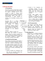
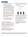
USER MANUAL POWERCOM® RF1 WRS7000DSI Copyright 2013 Copyright 2013 Dynamic Services International Inc. PowerCom Division. All rights reserved. Licensed software products are owned by PowerCom and are protected by United States copyright laws and international treaty provisions. Fleetwood Group, Inc. manufactures PowerCom RF1 for Dynamic Services International Inc. on OEM base. The relevant products are covered by U.S. and foreign patents, issued and pending. Information in this publication supersedes that in all previously published material. Specifications and pricing are subject to change without notice. Printed in the U.S.A. Dynamic Services International Inc. www.powercomars.com www.dsii.net Tel:212 997 2000 Email: [email protected] PowerCom RF1 is a registered trademark of Dynamic Services International Inc. Other trademarks contained herein are the property of their respective holders. Control Version 2.0 Date Oct 20,2011 Description Revision 2.x Original Table of Contents 1.0 PowerCom RF1 ...................................................................................................... 1 1.1 Introduction............................................................................................................... 1 1.2 Applications/Advantages ............................................................................................. 1 1.3 RF Communication ..................................................................................................... 1 1.4 About PowerCom® .................................................................................................... 1 1.5 Other PowerCom® Products….………………………………………………………………………………..2 2.0 Principles of Operation .......................................................................................... 2 3.0 System Description and Setup .............................................................................. 3 3.1 Room Layou .............................................................................................................. 3 3.2 Placement of the PowerCom RF1 System ..................................................................... 3 4.0 Button Descriptions ............................................................................................... 3 4.1 CLR key ..................................................................................................................... 3 4.2 Send Key ................................................................................................................... 3 4.3 !/10 Key .................................................................................................................... 3 4.4 Symbol Key (*SYM) .................................................................................................... 4 4.5 Number Keys ............................................................................................................. 4 5.0 System Operating Modes ...................................................................................... 4 6.0 Static Mode Keypad ............................................................................................... 4 7.0 Keypad Settings Retrieval ..................................................................................... 4 7.1 Keypad Locally ........................................................................................................... 4 7.2 Changing Keypad Number and Channel Number…….……………………….………………………. 5 8.0 Keypad Operation .................................................................................................. 5 8.1 Available Question Types ............................................................................................ 5 8.1.1 Single-Digit ........................................................................................................ 5 8.1.2 Multi-Alphanumeric ............................................................................................ 5 8.1.3 Range Display .................................................................................................... 5 8.1.4 Priority .............................................................................................................. 6 8.1.5 Sequence ........................................................................................................... 6 8.2 Changing Answer Types ............................................................................................ 6 8.3 Low Battery Warning ................................................................................................. 6 8.4 RF Performance ........................................................................................................ 6 9.0 Keypad Battery Replacement ............................................................................... 7 10.0 WRS97x Data Format and Command Lists ........................................................ 8 11.0 PowerCom® HID Base Station………………………………………………………………………..8 12.0 Software ............................................................................................................... 8 13.0 Accessories .......................................................................................................... 8 14.0 Limited Product Warranty................................................................................... 8 15.0 FCC, IC, and EU Compliance Information .......................................................... 9 15.1 Standards and Guidelines ......................................................................................... 9 15.2 FCC/IC Compliance................................................................................................. 10 15.3 EU Compliance ....................................................................................................... 10 16.0 Technical Specifications ...................................................................................... 2 17.0 Troubleshooting Procedures ............................................................................. 13 18.0 Index.…………….……………………………………………………………………………………………… 13 1.0 PowerCom RF1 1.1 Introduction This product consists of wireless (RF) handheld 14-key numeric keypads and a Base Station. The system is generally used to record answer/s to single or multiple choice question/s as part of a classroom presentation, decision-making session, focus group, or videoconference. It offers methods for collecting and immediately reporting group response. PowerCom RF1 is a wireless handheld response system that provides numeric data interaction for meeting or learning environments. Keypad responses are transmitted to the Base Station, which processes and delivers the information to the attached computer. Application software operates the Base Station and controls its associated Keypads. While the system’s hardware may offer powerful features, application software is the essential ingredient in applying the technology to generate useful results. 1.2 Applications/Advantages Many meeting and learning venues require a mechanism for audience interaction. Moreover, many seek a method of automating surveys and grading activities. PowerCom RF1 meets the need for such an interactive tool, bringing everyone together and instantly allowing measurement of interest, understanding, and involvement. Audience members can participate from their seat and personally indicate their opinions, ideas, and knowledge. Results of the interaction are immediately available, and their display offers presenters a valuable insight into the opinion and comprehension level of audience members. System setup typically involves handing a Keypad to every participant and connecting the Base Station to a computer. No Keypad wires or cabling need be installed prior to use. This allows fast, reliable, safe, and attractive installation. 1.3 RF Communication The Keypads communicate with the Base Station using wireless Radio Frequency (RF) technologies. The patented proprietary design has been rigorously tested and optimized for reliability and collection speed. 1.4 About PowerCom PowerCom® is an Audience Response Software division of Dynamic Services International, Inc. (DSI). DSI was founded in 1988 with a mission to help businesses of all sizes to build stronger communications with their customers, employees and business partners. With a focus on building strong autonomous communication channels, DSI is able to help companies collect and exchange valuable business information. Our technology solutions focus around generating fewer errors, fewer returned documents, and fewer lost documents, as well as a much faster response time. As a premier provider of Information Technology and Business Processes, DSI © 2013 Dynamic Services International Inc. PowerCom Division. All Rights Reserved. ǀ 1-212-997-2000ǀ www.PowerComARS.com Page 1 is a trusted technology partner for many commercial and government clients. 1.5 Other PowerCom® Products PowerCom® has developed its software in 9 major languages and offices around the world; we are committed to bringing the highest level of products and customer service to users in every country! We provide Audience Response System distribution, rental service, and full support to PowerCom® customers all over the world! With Interactive PowerPoint Presentation software in nine languages, PowerCom® provides the highest quality audience response systems for international businesses. Recognized by Microsoft as a Partner, PowerCom® is the most respected Interactive Presentation Software developer in the business. We guarantee that we provide the lowest priced ARS packages and rental service in the world! For more information on these products or our customization capability, please visit our website at http://www.powercomars.com. 2.0 Principles of Operation PowerCom RF1 uses the latest in 2.4 GHz frequency hopping spread spectrum (FHSS) transceivers. FHSS offers excellent range, immunity to interference, and signal security. This wireless technology can turn any meeting into a dynamic interactive experience for each participant without having to deal with a nightmare of cables and connectors. needs of users. So whether the need is for the simplest possible system or an impressive system that involves impressing top clients, PowerCom® has it. Figure 1. System Diagram The WRS970DSI or WRS971DSI Base Station is the control center for the system and operates according to commands issued PowerCom software. The Base Station can be set to any of the 75 available Base IDs through the DLL module. Each Base Station can process responses from up to 500 keypads. A radio frequency packet is continuously sent out by the Base Station when the unit is powered on. Each Base Station’s packet can only be received by keypads that have been set to the same Base ID. All of PowerCom's hardware is provided by close partner, Fleetwood Industries. Because of this, every keypad represents the pinnacle of audience response system development. Each is designed for the © 2013 Dynamic Services International Inc. PowerCom Division. All Rights Reserved. ǀ 1-212-997-2000ǀ www.PowerComARS.com Page 2 4.0 Button Descriptions 3.0 System Description and Setup Figure 3. RF1 keypad 3.1 Room Layout Figure 2. Typical Room Layout 4.1 CLR key 3.2 Placement of the PowerCom RF1 System The Base Station can be located anywhere in the area where the keypads are to be used. PowerCom RF1 keypads can operate in a room up to 650’ x 650’ (WRS970-DSI) in size with the base station being placed in the center of the venue. The total range of the system is determined by the base and keypad, whichever is shorter. Despite a robust communication system, walls and some other 2.4 GHz devices can moderately to severely limit the system’s performance. If coverage of a larger area is necessary, elevation of the Base Station or centering in room can usually improve the reception of the keypad signals. NOTE: Due to the properties of signals operating at 2.4 GHz, we do not recommend placing any walls between the base station and the keypads. The material in a wall tends to absorb the RF signal and some reduced performance might be observed. The CLR key is used when connecting to a system while the keypad in configured for operation. The CLR key can also be used to cancel actions. In Static mode operation, the CLR key can cancel a vote rather than wait for the timeout period. 4.2 Send Key The Send key is used to complete multi-digit entries. Single-digit voting does not use the send key. The Send key is also used to begin connecting to a base. 4.3 !/10 Key This serves as an alert key which can send a special packet to the Base Station to alert the presenter like raise hand, in case the participant has a question or clarification. The participant can press this key during the slide show or out of slide show. There will be a pop up screen for raise hand. This key is applicable for Likert Scale type (0 to 10) of question. If there will be 10 answer choices for this type of question, !/10 key is used to choose option 10. © 2013 Dynamic Services International Inc. PowerCom Division. All Rights Reserved. ǀ 1-212-997-2000ǀ www.PowerComARS.com Page 3 6.0 Static Mode Keypad 4.4 Symbol Key (*SYM) This key is mainly used to separate answers for multiple answer questions. Please allow a second or two to pass before entering any numbers after using the symbol key to ensure that the number appears after the symbol and doesn’t override the symbol. 4.5 Number Keys A keypad in Static mode is configured to a specific Base ID and address. Each keypad on a system must be set to the same Base ID of the Base Station to be used. The address of each keypad in a system must be a unique number between 1 and 500. To obtain best system performance, start at address 1 and continue up to the number of keypads to be used. Once the system is configured, the settings are maintained indefinitely. The keypad can only be used on the Base ID it is programmed. If more flexibility is desired (moving a keypad from base to base or room to room, for example) use Dynamic mode operation. Note: PowerCom RF1 only supports Static address mode, no Dynamic mode operation. 7.0 Keypad Settings Retrieval The number keys are used for voting and changing settings. Some question types will require these keys to be used for voting. If the question type is alpha, then the display will show the letter and participants will key in the number that corresponds to the letter of their answer/s. 5.0 System Operating Modes PowerCom RF1 only supports Static address mode, not the Dynamic mode operation. Both the base and the keypads must be configured to the Static mode, as they are not interoperable. Note: The Base Station has both dynamic and static mode options, so do not change to dynamic mode, otherwise, you can never connect a dynamic mode base to static mode keypad 7.1 Keypad Locally To verify keypad settings, hold the 1 and CLR key simultaneously for 3 seconds. The LED will begin flashing to indicate the Base ID and address. Green flashes represent numbers, and red flashes are used to separate the green flashes. The format is as follows: Tens Digit of Base ID Red Flash Ones Digit of Base ID Red Flash Small pause Hundreds digit of keypad Address Red flash Tens digit of keypad Address Red flash Ones digit of keypad Address Red flash © 2013 Dynamic Services International Inc. PowerCom Division. All Rights Reserved. ǀ 1-212-997-2000ǀ www.PowerComARS.com Page 4 7.2 Changing Keypad Number and Channel Number Make sure base station is detected properly. Choose “Change Keypad Channel and Address” from the drop down menu of the Device group in Powercom Tab. Follow the instructions to continue. 8.0 Keypad Operation 8.1 Available Question Types All answer to question types is determined by the PowerCom software. The software must be connected to the base for data to be sent from the keypad. An attempt to send data before then may either blink the green LED to alert the keypad is being polled or the keypad’s green LED will remain lit if no base is polling. In either case, when the keypad timeout expires, the red LED lights. The keypad supports the question types described below: 8.1.1 Single-Digit This question type allows for up to 10 programmable answer choices (1-10, 0 is used to represent 10) and only one choice is allowed as an answer. The keypad user only needs to press the key corresponding to the desired answer; the “Send” key is not needed. The LED lights green when a key is pressed. It turns off once the vote has successfully been sent or it will light red if the vote could not be sent. If the key is locked out by the software, the light changes from green to red and remains red until a valid key is entered or the keypad times out after 9 seconds. Another key can be entered at any time to change a vote value. By default, PowerCom software accepts the last key pressed as the final vote. 8.1.2 Multi-Alphanumeric This question type allows for up to 30 programmable answer choices (1-30). For multiple answers each choice must be separated by use of the “*SYM” key. The “Send” key must be pressed when finished with inputs. The keypad allows up to 12 digits for an entry of the answer. If the answer is more than 12 digits, please enter the answer by two entries or more. Please press asterisk in the front of the next entry to make sure that both entries will be recognized as one answer. The green LED lights to full brightness briefly and then dims. The dim light means the keypad is waiting for another digit. Either enter another digit or press the Send key to complete the vote. Each valid key press extends the 9 second timeout period for entering more data. The vote is successful when the green light goes out after pressing the send key. If it changes to red and then turns off, the vote did not complete (either before or after the send key is pressed). Most software packages only save the last received vote so if a mistake was made, either wait the timeout period or press Send and enter the vote again. The asterisk key can be used in this mode if allowed through software. 8.1.3 Range Display In this question type, you set a list of numeric ranges. Keypad users answer the question presented by inputting a multi- digit and pressing the “Send” key © 2013 Dynamic Services International Inc. PowerCom Division. All Rights Reserved. ǀ 1-212-997-2000ǀ www.PowerComARS.com Page 5 when done. Answers are tallied based on which range answers fall in. 8.1.4 Priority This question type allows for up to 30 programmable answer choices (1-30). Keypad users are asked to input the choices in order according to the question’s given criteria. Each choice must be separated by use of the “*SYM” key. The “Send” key must be pressed when finished with inputs. The Result displays the first priority as the default, presenter uses Ctrl + numeric key to change display of other priority. 8.1.5 Sequence This question type allows users to put the answers into correct sequence. Only correct sequence will get the point, and the final point will be published in Polling Detail. When putting in the answers, each answer should be separated by”*”. 8.2 Changing Answer Types 8.3 Low Battery Warning The keypad contains a feature to alert when the battery is low and should be replaced. After a vote, the keypad will blink the red LED four times before turning off. This occurs on each vote until the battery is replaced. The battery should be replaced at earliest convenience to ensure operation continues. The keypad battery level is also sent to the software on each vote regardless of the level. This can be useful to find full, partial and low batteries if the software contains this feature. 8.4 RF Performance The WRS97x system is frequency hopping to avoid interferences from other products. However, a heavily used wireless internet access point can make certain frequencies more difficult to transmit on. The keypad blinks the green LED when sending the vote data if it has trouble transmitting to the base. This may be caused by other interference or a keypad that is near the range limit of keypad to base. Table 1. Wifi Channel Avoidance Settings Since only PowerCom software determines what the answer type is going to be, no configuration of the keypad is necessary. There is a scenario where the keypad may be in the process of sending vote data when a new question gets asked. The previous data transmission may be cancelled. The keypad will light the red LED to alert that the transmission may not have completed successfully. This can also happen if a multi-digit answer is partially entered on the keypad and another question is asked. The keypad will light the red LED and the previously entered data is cleared. © 2013 Dynamic Services International Inc. PowerCom Division. All Rights Reserved. ǀ 1-212-997-2000ǀ www.PowerComARS.com Page 6 There are three commonly used channels for wireless internet access points: Channel 1, 6 and 11. The base station can be set up to avoid 1 to 2 of these channels if needed. The available settings are displayed in Table 1. See your network administrator for help in determining the optimum setting. 9.0 Keypad Battery Replacement For areas that don’t have wireless internet issues but are using multiple PowerCom systems in nearby rooms, it is recommended to lower the power level setting to avoid system interference. INSTRUCTIONS: Set the power to what is necessary to reliably cover the room or area in which the system is operating. The power level options are displayed in Table 2 for the PowerCom RF1 keypad. Table 2. Power Level Setting Power Level Low Mid High Europe Max Each keypad is powered from a single CR2032 Lithium Coin cell battery. One fresh CR2032 battery can last for 2 years or up to 20,000 votes in Static mode, whichever comes first. 1. Remove screw from case back. 2. Separate case parts at screw location. 3. Using a non-metallic object, carefully push the battery out of the retainer from the back side. 4. Pull the rest of the way out. 5. Slide in new battery with positive side away from circuit board. Figure 5. Keypad Battery Replacement Power (mW) 0.01 mW 0.1 mW 0.3 mW 1 mW (default for all systems) Figure 4. Wi-Fi Frequency Avoidance © 2013 Dynamic Services International Inc. PowerCom Division. All Rights Reserved. ǀ 1-212-997-2000ǀ www.PowerComARS.com Page 7 10.0 WRS97x Data Format and Command Lists The Base Station data format, command lists, and associated microcode are proprietary to PowerCom. People who wish to develop their own applications may purchase the PowerCom RF1 WRS970 API. This is a software developer’s toolkit that includes the necessary communication drivers for the base station. 11.0 PowerCom® HID Base Station Model Number: WRS970-DSIH, WRS971-DSIH PowerCom® offers HID compliant base stations. With these new PowerCom base stations, no need to load a USB driver anymore, you just have to connect the base to your computer and start using the software. Both has 2.4 GHz frequency hopping spread spectrum (FHSS) transceivers. Frequency Synthesized. One PowerCom RF1 Base Station per 500 keypads of the same channel identity in a room. 31 RF Base Station identifiers allows up to 15,500 pads per room. 12.0 Software PowerCom is PowerPoint Add-in software available for RF1 keypad and it can be installed for Office 2007, Office 2010 and Office 2013. Please contact [email protected] or visit our website www.powercomars.com for more information about PowerCom software. 13.0 Accessories Call PowerCom for information on available storage/shipping cases, extra cables or power supply kits for PowerCom RF1 system. 14.0 Limited Product Warranty Limited Product Warranty PowerCom warrants its serial components for a period of 24 months from the date of manufacture for any material or workmanship defect in the product. This warranty does not extend to batteries or any product component, which has been subjected to misuse, neglect, accidental breakage, improper installation, use outside of present guidelines, or alteration outside of our factory. PowerCom Base Stations and Keypads use internal antennas built directly on the printed circuit board. Modifying the antennas in any way will result in reduced range and will void the warranty. There are no user serviceable parts inside PowerCom Base Stations or Keypads. PowerCom agrees to remedy, at the factory, any product defect, or at its discretion, replace any component or part of the product provided the owner complies with the following procedures: 1. The owner is to determine that the problem is not the battery or a faulty or improper connection with the personal computer or power source. 2. The owner will contact PowerCom during standard hours Monday through Friday 9:00 AM to 6:00 PM Eastern Standard Time at: 212-997-2000 or [email protected] to obtain a Return Material Authorization (RMA) number prior to shipping the product back to the factory. © 2013 Dynamic Services International Inc. PowerCom Division. All Rights Reserved. ǀ 1-212-997-2000ǀ www.PowerComARS.com Page 8 3. The owner will send the defective component via prepaid freight to: Fleetwood Group, Inc. Electronics Division Product Service Coordinator RMA#: 11832 James Street Holland, MI 49424 4. If the factory determines the defect is due to negligence or oversight on the part of the owner, the owner will be invoiced for the cost of the repair. 15.0 FCC, IC, and EU Compliance Information WRS7000DSI contains N240D RF Module Responsible Party Pertaining to the Declaration of Conformity Fleetwood Group, Inc. 11832 James Street Holland, MI 49424 Attn: Product Service Coordinator Phone: 888-467-3759 15.1 Standards and Guidelines This device complies European Directives Regulations: with the following and USA/Canada Directive 1999/5/EC on radio equipment and telecommunication terminal equipment and the mutual recognition of their conformity Directive 2006/95/EC on the harmonization of laws of member states related to electrical equipment designed for use within certain voltage limits. The USA Federal Commission (FCC) Regulations. Communications Rules and Industry Canada Rules and Regulations This device complies with the following national and international standards: EN 301 489-1 V1.6.1: 2005: EMR; EMC standard for radio equipment and services. Part 1: Common technical requirements. EN 301 489-17 V1.2.1: 2002: EMR; EMC standard for radio equipment and services. Part 17: Specific conditions for 2.4 GHz wideband transmission systems and 5 GHz high performance RLAN equipment. EN 300 328 V1.7.1: Electromagnetic compatibility and Radio spectrum Matters (ERM);Wideband transmission systems; Data transmission equipment operating in the 2,4 GHz ISM band and using wide band modulation techniques. EN 60950-1: 2001 + A11: 2004: Information technology equipment – Safety. Part 1: General requirements FCC Part 15B, 15.247: 10-01-2006: Radio Frequency devices: Operation within the bands 902-928 MHz, 2400-2483.5 MHz, and 5725-5850 MHz. IC RSS-210 Issue 7: 2007: Low power license-except radio-communications devices (all frequency bands): Category 1 equipment. © 2013 Dynamic Services International Inc. PowerCom Division. All Rights Reserved. ǀ 1-212-997-2000ǀ www.PowerComARS.com Page 9 15.2 FCC/IC Compliance This device complies with Part 15 of the FCC Rules and RSS-210 of the Industry Canada Rules. Operation is subject to the following two conditions: (1) this device may not cause interference and (2) this device must accept any interference, including interference that may cause undesired operation of the device. The user is cautioned that changes or modifications to the device that are not approved by the manufacturer could void the user’s authority to operate the device. 15.3 EU Compliance This device is a 2.4 GHz low power response system controller intended for residential and commercial use in all EU and EFTA member states. Notice The base and keypad units may be susceptible to Electrostatic Discharge (ESD) and other similar fast transient events causing system interruption. Should system interruption occur, reboot computer, reset base unit by disconnecting and reconnecting USB cable and push any key on keypads which have powered down. © 2013 Dynamic Services International Inc. PowerCom Division. All Rights Reserved. ǀ 1-212-997-2000ǀ www.PowerComARS.com Page 10 16.0 Technical Specifications © 2013 Dynamic Services International Inc. PowerCom Division. All Rights Reserved. ǀ 1-212-997-2000ǀ www.PowerComARS.com Page 11 17.0 Troubleshooting Procedures ISSUE Keypad does not turn on Poor RF Performance Short range with keypads Keypad vote not sending POSSIBLE CAUSE SOLUTION Battery may be inserted backwards. Check that the positive side of the battery is touching the coin cell retainer. Battery is dead. Replace the battery. Base not in open area. Do not place the base inside cabinets. Base located too close to other electronic equipment Place the base away from other electronic devices, such as TV’s, DVD/VCR players and similar. More than one base unit on the same Base ID Check that the bases covering an area are not on the same Base ID. Other Interference Always physically separate other radio devices by at least 10’ (3 m). This includes WiFi, Bluetooth, ZigBee and other similar devices. Multiple Base Stations are too close Keep base stations separated and do not stack units. Keypad battery dead. Replace the coin cell battery. Keypad operating too far from base station. Move closer to the base station to see if voting improves. Power level setting too low. Check that the power level setting of the system is appropriate for the range trying to be achieved (Some countries have restrictions as to the power level setting allowed. See Section 15.0). Interference See “Poor RF Performance”. Keypad Base ID setting and base setting are not matched. Change either the base or keypads so they match. Note: We cannot possible list all troubleshooting issues here. We only list the common hardware issues. Please search www.powercomars.com web site to locate the issue and possible solution. © 2013 Dynamic Services International Inc. PowerCom Division. All Rights Reserved. ǀ 1-212-997-2000ǀ www.PowerComARS.com Page 12 18.0 Index A R Accessories, 8 Address Settings, 4 Answer Types, 5-6 Return Parts, 8 RF Communication, 1 RF Performance, 6 B S Batteries, 7 Service, 8 Software, 7 I Interface, 7 T O Technical Specifications, 10 Troubleshooting, 11 Operating Modes, 4 Static, 4 V P Patent information, 1 PowerCom Products, 2 Voting, 5 W Warranty, 8 © 2013 Dynamic Services International Inc. PowerCom Division. All Rights Reserved. ǀ 1-212-997-2000ǀ www.PowerComARS.com Page 13