1
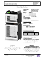
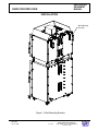
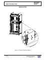
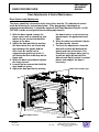
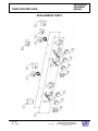
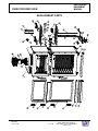
AHPO-6/18 GOLD
Proofer Oven
Installation and Service guide
For Service and Installation Personnel Only
For information or technical assistance, call
011-314-231-1130
PN 512116M
RESTAURANT
EQUIPMENT
MANUAL
DUKE PROOFER OVEN
TABLE OF CONTENTS
GENERAL SPECIFICATIONS ................................................................................................ 3
INSTALLATION ................................................................................................................... 4-7
DOOR ADJUSTMENTS & GASKET MAINTENANCE ........................................................... 8
REVERSING OVEN DOOR SWING DIRECTION................................................................... 8
PROOFER DRIP CHANNEL REVERSAL .............................................................................. 9
DOOR GASKET LEAK ADJUSTMENTS ............................................................................. 10
GASKET REPLACEMENT ................................................................................................... 11
ELECTRICAL SCHEMATICS ............................................................................................... 12
REPLACEMENT PARTS ................................................................................................. 13-15
NOTE:
This manual intended to be used by qualified service personnel only.
WARNING:
A disconnection means having a contact spacing of at least 3 mm in all poles shall be
incorporated in the fixed wiring. Appliance power switches do not provide sufficient
spacing to be used as a disconnection means.
REVISED:
June 9, 2004
2 of 16
DUKE PROOFER OVEN
DUKE MANUFACTURING CO.
TOLL FREE 1-800-735-DUKE(3853)
1-314-231-1130
RESTAURANT
EQUIPMENT
MANUAL
DUKE PROOFER OVEN
General Specifications
Duke Manufacturing Co.
2305 North Broadway
St. Louis, MO 63102
Model #:
AHPO-6/18
Serial #:
__________________
Date Received: __________________
Date Installed: __________________
Toll Free Telephone: 1-800-735-3853
Fax:
1-314-231-5074
Service Referral #:
__________________
Local Service Name: __________________
_____________________________________
Local Service #:
__________________
Supplier Name:
Address:
General Specifications
Model #:
AHPO-6/18
Overall Dimensions
Height: 77 3/4 in./197.5cm
Width: 37 1/4 in./94.6cm
Depth: 27 1/4 in./69.2cm
ELECTRICAL SPECIFICATIONS
Phase
1
3N
Volts
230
230/400
Shipping Weight:
AMPS
26.5
16.0
WATTS
6100
6100
550lbs / 250kg
Installation Requirements
Power Connection: Unit is to be permanently
attached to fixed wiring using conduit or
cable only. To be installed by qualified
service personnel only.
NO ALUMINUM WIRING ALLOWED
WARNING:
A disconnection means having a
contact spacing of at least 3 mm in all
poles shall be incorporated in the fixed
wiring. Appliance power switches do
not provide sufficient spacing to be
used as a disconnection means.
WARNING:
Risk of Injury.
Unit must be permanently attached to
wall using wall-mounting brackets. See
Figure 1.1 on page 4
REVISED:
June 9, 2004
3 of 16
DUKE PROOFER OVEN
DUKE MANUFACTURING CO.
TOLL FREE 1-800-735-DUKE(3853)
1-314-231-1130
RESTAURANT
EQUIPMENT
MANUAL
DUKE PROOFER OVEN
INSTALLATION
INSPECTION
•
Damage - Inspect the exterior of the shipping container carefully and note any damage on the delivery
receipt. Remove the shipping container and check for damage to the oven. If there is any damage file a
freight claim with the carrier and call Duke at 800-735-3853.
•
Voltage - Compare the voltage and phase from the oven specification label to the power supply for the oven
and call Duke if there is a difference. If the phase is wrong, a qualified service technician can change the
wire connections inside the oven to correct the problem.
•
Doors - Check the swing of the door. The hinge side can be changed by following the instructions on page
7. The door swing direction can be changed in the field after you have a new drip channel for the proofer
door. Call Duke to get the new drip channel for the proofer door.
•
Seals - Check the door seal and make sure both doors close completely. If they do not close and seal
properly, call Duke for assistance. See instructions on page 9.
SETUP
•
Wall Brackets – To prevent tipping, securely attach oven to wall using brackets shown in figure 1.1 on page
4.
•
Lights - Remove the light bulbs from the shipping container and install them in the oven and proofer before
the oven is connected to the power supply. The light bulb covers can be removed by turning them counter clockwise. Make sure the gasket is in place when replacing the covers. If you replace the light bulbs, make
sure they are the correct voltage and a maximum rating of 40 watts. Contact Duke Manufacturing Service
for long life replacement bulbs.
•
Racks – Locate oven and proofer racks and removing all packing materials. Install three (3) racks onto the
slides in the oven cavity and the remainder into the slots in the proofer cavity.
•
Water Tray – Locate water drip tray on the front of the proofer. Ensure tray is slid all the way to the hinge
side of the proofer door. This will ensure water from the proofer door drips into the tray and not onto the
floor.
•
Electrical Connections – Connect oven to supply lines as shown in figure 1.2 on page 5.
•
Thermal Cutout Reset Button – Ensure Thermal Cutout is set by pressing reset pushbutton on right side
of the oven. See figure 1.3 on page 6 for location.
•
Testing
1.
2.
3.
4.
5.
6.
7.
Turn the oven and proofer power switches to the ON position.
Set the oven thermostat at 177° C, the proofer thermostat at 40° C, and the proofer humidity at 3.
Ensure all of the indicator lights are on.
Ensure that the oven and proofer fans are turning and the lights are on.
Check that the oven fan stops rotating when the oven door is open. Close the door to continue.
Set both timers to 20 minutes and check to make sure they time down and the buzzers work.
Allow the oven and proofer to pre-heat for at least 30 minutes. Ensure the Heat Indicator Lamps
periodically turn off.
If there are any problems, call the service department at Duke Manufacturing Company for assistance before
you call a service agency. If the problem is an operator or procedural error you will be liable for the service
charges.
Your Duke AHPO Gold Proofer Oven is now ready to operate.
REVISED:
June 9, 2004
4 of 16
DUKE PROOFER OVEN
DUKE MANUFACTURING CO.
TOLL FREE 1-800-735-DUKE(3853)
1-314-231-1130
RESTAURANT
EQUIPMENT
MANUAL
DUKE PROOFER OVEN
INSTALLATION
Wall Mounting
Brackets
Figure 1.1 Wall Mounting Brackets
REVISED:
June 9, 2004
5 of 16
DUKE PROOFER OVEN
DUKE MANUFACTURING CO.
TOLL FREE 1-800-735-DUKE(3853)
1-314-231-1130
RESTAURANT
EQUIPMENT
MANUAL
DUKE PROOFER OVEN
INSTALLATION
Terminal Block Location
Three Phase Terminal Block
Single Phase Terminal Block
Figure 1.2 Electrical Connections
REVISED:
June 9, 2004
6 of 16
DUKE PROOFER OVEN
DUKE MANUFACTURING CO.
TOLL FREE 1-800-735-DUKE(3853)
1-314-231-1130
RESTAURANT
EQUIPMENT
MANUAL
DUKE PROOFER OVEN
INSTALLATION
Figure 1.3 Thermal Cutout Reset Button
REVISED:
June 9, 2004
7 of 16
DUKE PROOFER OVEN
DUKE MANUFACTURING CO.
TOLL FREE 1-800-735-DUKE(3853)
1-314-231-1130
RESTAURANT
EQUIPMENT
MANUAL
DUKE PROOFER OVEN
Door Adjustments & Gasket Maintenance
Reversing Oven Door Swing Direction
NOTE
If you reverse the Proofer door you must have the reverse drip channel for the bottom
of the door. Call Duke at 800-735-3853 to order the drip channel before you
reverse the door swing.
1. Remove cover from hinges to
expose the screws that hold the
hinge to the front of the oven.
2. Remove the hinge screws and door
from the oven.
3. Remove the door handle screws and
flip the door handle over and replace
it on the door.
4. Remove the six screws on the front
of the oven to expose the hinge
screw holes for the other swing
direction.
5. Use the six screws to fill the unused
hinge screw holes on the front of the
oven.
6. Remove the latch strike plate from
the front of the oven and move it to
the other side. Use the screws from
the other side to fill the screw holes
that are no longer used.
7. Position the door on the front of the
oven and tighten the hinge screws.
Make sure the door is level with the
oven body before the screws are
tightened permanently.
Door Handle Screws
Hinge Cover and Screws
REVISED:
June 9, 2004
8 of 16
DUKE PROOFER OVEN
DUKE MANUFACTURING CO.
TOLL FREE 1-800-735-DUKE(3853)
1-314-231-1130
RESTAURANT
EQUIPMENT
MANUAL
DUKE PROOFER OVEN
Door Adjustments & Gasket Maintenance
Proofer Drip Channel Reversal
The proofer door has a sloped drip channel on the bottom that directs any water that
drips down the door in to the water pan below the door. When the door swing is
reversed this drip channel must be replaced with a new channel that has the slope in
the proper direction. Contact Duke Manufacturing Service for a new drip channel
before changing door swing direction.
1. Follow the directions for removing
the door on the last page. When the
door is off you can then replace the
drip channel.
3. Locate the new drip channel on the
other end of the door. Make sure that
the slope is directed to the hinge
side of the door.
2. Remove the screws that hold the
drip channel on and remove the drip
channel. Use the same screws to fill
the empty holes after the drip
channel is off.
4. Fasten the drip channel to the door
with the self tapping screws
provided with the new drip channel.
5. Follow the directions for mounting
the door on the last page.
Right Hinge Drip Channel
Left Hinge Drip Channel
REVISED:
June 9, 2004
9 of 16
DUKE PROOFER OVEN
DUKE MANUFACTURING CO.
TOLL FREE 1-800-735-DUKE(3853)
1-314-231-1130
RESTAURANT
EQUIPMENT
MANUAL
DUKE PROOFER OVEN
Door Adjustments & Gasket Maintenance
Door Gasket Leak Adjustments
The doors should be checked for leaks every three months. The adjustment can be
made by following the instructions below. If the door gasket is damaged, or
compressed permanently, it should be replaced. Call Duke Manufacturing Co. at 800735-3853 to order a new gasket before making adjustments.
1. With the door closed, remove the
hinge covers with a screwdriver and
loosen the six screws that hold the
hinges to the door.
2. Adjust the door position by moving
the door frame in or out to seal any
gaps between the gasket and the
oven front. Be careful not to
compress the gasket too much, it
will cause the door to bind up on the
hinge side.
3. When the door is positioned, tighten
the hinge screws.
4. Loosen the two screws that hold the
door handle in place.
5. Adjust the door position by moving
the door frame in or out to seal any
gaps between the gasket and oven
front.
6. When the door is positioned, tighten
the door handle screws.
7. To check the adjustment, close the
door with a dollar bill between the
gasket and front of the oven. You
should feel resistance when you try
to pull the dollar bill out with the
door closed. Do this check in several
places and readjust the door if
necessary.
Move Door to adjust gap
Door Hinge Screws
Door Handle Screws
REVISED:
June 9, 2004
10 of 16
DUKE PROOFER OVEN
DUKE MANUFACTURING CO.
TOLL FREE 1-800-735-DUKE(3853)
1-314-231-1130
RESTAURANT
EQUIPMENT
MANUAL
DUKE PROOFER OVEN
Door Adjustments & Gasket Maintenance
NOTE
If the door gasket is damaged or overly compressed, it should be replaced.
Call Duke Manufacturing Co. for a new gasket.
Gasket Replacement
1. Remove the old gasket by pulling it
out of the groove in the door frame.
2. Clean the groove with a screwdriver
or other flat-bladed tool to remove
any dirt or gasket pieces.
3. Press the new gasket into the
groove. Make sure it is fully seated
in the groove and flat against the
door frame.
4. Check the door adjustment to make
sure there are not any leaks or the
new gasket is compressed too
much, making the door hard to
close.
Gasket Groove
Door Gasket
REVISED:
June 9, 2004
11 of 16
DUKE PROOFER OVEN
DUKE MANUFACTURING CO.
TOLL FREE 1-800-735-DUKE(3853)
1-314-231-1130
RESTAURANT
EQUIPMENT
MANUAL
DUKE PROOFER OVEN
ELECTRICAL SCHEMATICS
REVISED:
June 9, 2004
12 of 16
DUKE PROOFER OVEN
DUKE MANUFACTURING CO.
TOLL FREE 1-800-735-DUKE(3853)
1-314-231-1130
RESTAURANT
EQUIPMENT
MANUAL
DUKE PROOFER OVEN
REPLACEMENT PARTS
REVISED:
June 9, 2004
13 of 16
DUKE PROOFER OVEN
DUKE MANUFACTURING CO.
TOLL FREE 1-800-735-DUKE(3853)
1-314-231-1130
RESTAURANT
EQUIPMENT
MANUAL
DUKE PROOFER OVEN
REPLACEMENT PARTS
REVISED:
June 9, 2004
14 of 16
DUKE PROOFER OVEN
DUKE MANUFACTURING CO.
TOLL FREE 1-800-735-DUKE(3853)
1-314-231-1130
RESTAURANT
EQUIPMENT
MANUAL
DUKE PROOFER OVEN
REPLACEMENT PARTS
Item #
Part #
Description
1
2
3
4
5
6
7
10
11
12
13
14
15
16
17
18
19
21
22
23
24
25
26
27
28
29
30
31
32
33
33
34
35
35
36
37
38
39
40
41
42
43
43
44
45
46
47
48
49
512852
502800
512972
512850
512949
512068
502190
502805
153142
154470
154039
502177
512888
512843
512821
154375
154547
156041
502341
502342
512955
512956
512849
600103
512872
154019
512836
512835
512935
155977
155979
155981
155976
155978
512817
512905
512909
512910
512914
512913
502180
512840
512941
502195
156350
512833
502744
502475
502338
Thermostat , Oven
Buzzer
Timer , 60 minute , 50 Hz
Thermostat , proofer
Thermostat , humidity
Light , indicator
Mylar , control panel
Switch , power
Knob
Motor Oven – 230V
Blower Wheel , Oven
Thermostat , high limit
Mylar , Subway
Compression spring , door switch assembly
Plunger rod , door switch
Element , 2.5 KW , oven
Wire rack
Gasket , lens
Bulb , light, 230V, 40 Watt
Fixture , Light Assembly
Cooling fan
Fan guard
Element , 250 watt, proofer
Element , 450 watt, humidity proofer, ( 1 Kit )
Motor , proofer – 208/240 volt
Blower , forward curve , proofer
Castor , swivel
Castor , locking w/brake
Drip pan
Housing , drip edge – left hinged door
Housing , drip edge – right hinged door
Gutter , drip edge
Channel , drip edge – left hinged door
Channel , drip edge – right hinged door
Hinge , door
Handle & latch assembly
Proofer door assembly
Oven door assembly
Gasket , proofer door
Gasket , oven door
Cover, Motor
Terminal Block, 3 Pole (230 V single phase)
Terminal Block, 4 Pole (230/400V 3 Phase)
Cover Access
Capacitor, RFI Filter
Contactor, 30 A
Guard, Oven Light
Guard, Proofer Light
Fan, Motor
REVISED:
June 9, 2004
15 of 16
DUKE PROOFER OVEN
DUKE MANUFACTURING CO.
TOLL FREE 1-800-735-DUKE(3853)
1-314-231-1130