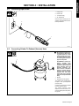
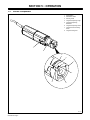
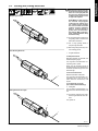
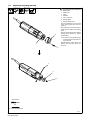
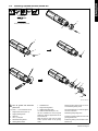
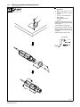
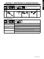
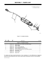
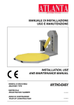
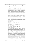
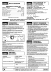
1
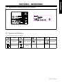
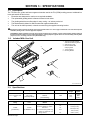
2010−05
TIG (GTAW) Welding
FRANÇAIS
ENGLISH
OM-230 915D
ESPAÑOL
Description
Tungsten Grinder
Triad Tungsten Grinder
TTG Plus
Owner’s Manual
Manuel de L’utilisateur
Manual del Operador
File: TIG (GTAW)
TABLE OF CONTENTS
SECTION 1 − SAFETY PRECAUTIONS - READ BEFORE USING . . . . . . . . . . . . . . . . . . . . . . . . . . . . . . . . . . . 1
1-1. Symbol Usage . . . . . . . . . . . . . . . . . . . . . . . . . . . . . . . . . . . . . . . . . . . . . . . . . . . . . . . . . . . . . . . . . . . . . . . . 1
1-2. Tungsten Grinding Hazards . . . . . . . . . . . . . . . . . . . . . . . . . . . . . . . . . . . . . . . . . . . . . . . . . . . . . . . . . . . . . 1
1-3. California Proposition 65 Warnings . . . . . . . . . . . . . . . . . . . . . . . . . . . . . . . . . . . . . . . . . . . . . . . . . . . . . . . 2
1-4. Principal Safety Standards . . . . . . . . . . . . . . . . . . . . . . . . . . . . . . . . . . . . . . . . . . . . . . . . . . . . . . . . . . . . . 2
SECTION 2 − DEFINITIONS . . . . . . . . . . . . . . . . . . . . . . . . . . . . . . . . . . . . . . . . . . . . . . . . . . . . . . . . . . . . . . . . . . . 3
2-1. Manufacturer’s Rating Label For CE Products . . . . . . . . . . . . . . . . . . . . . . . . . . . . . . . . . . . . . . . . . . . . . 3
2-2. Symbols And Definitions . . . . . . . . . . . . . . . . . . . . . . . . . . . . . . . . . . . . . . . . . . . . . . . . . . . . . . . . . . . . . . . 3
SECTION 3 − SPECIFICATIONS . . . . . . . . . . . . . . . . . . . . . . . . . . . . . . . . . . . . . . . . . . . . . . . . . . . . . . . . . . . . . . . . 4
3-1. Description . . . . . . . . . . . . . . . . . . . . . . . . . . . . . . . . . . . . . . . . . . . . . . . . . . . . . . . . . . . . . . . . . . . . . . . . . . 4
3-2. Included With Your Unit . . . . . . . . . . . . . . . . . . . . . . . . . . . . . . . . . . . . . . . . . . . . . . . . . . . . . . . . . . . . . . . . 4
3-3. Specifications . . . . . . . . . . . . . . . . . . . . . . . . . . . . . . . . . . . . . . . . . . . . . . . . . . . . . . . . . . . . . . . . . . . . . . . . 4
SECTION 4 − INSTALLATION . . . . . . . . . . . . . . . . . . . . . . . . . . . . . . . . . . . . . . . . . . . . . . . . . . . . . . . . . . . . . . . . . . 5
4-1. Connecting Input Power . . . . . . . . . . . . . . . . . . . . . . . . . . . . . . . . . . . . . . . . . . . . . . . . . . . . . . . . . . . . . . . . 5
4-2. Connecting Grinder To Exhaust (Vacuum) Hose . . . . . . . . . . . . . . . . . . . . . . . . . . . . . . . . . . . . . . . . . . . . 5
SECTION 5 − OPERATION . . . . . . . . . . . . . . . . . . . . . . . . . . . . . . . . . . . . . . . . . . . . . . . . . . . . . . . . . . . . . . . . . . . . 6
5-1. Grinder Components . . . . . . . . . . . . . . . . . . . . . . . . . . . . . . . . . . . . . . . . . . . . . . . . . . . . . . . . . . . . . . . . . . 6
5-2. Grinding And Cutting Electrodes . . . . . . . . . . . . . . . . . . . . . . . . . . . . . . . . . . . . . . . . . . . . . . . . . . . . . . . . . 7
5-3. Replacing Grinding Wheels . . . . . . . . . . . . . . . . . . . . . . . . . . . . . . . . . . . . . . . . . . . . . . . . . . . . . . . . . . . . . 8
5-4. Installing Optional Double-Decker Kit . . . . . . . . . . . . . . . . . . . . . . . . . . . . . . . . . . . . . . . . . . . . . . . . . . . . . 9
5-5. Installing Grinder Mounting Bracket . . . . . . . . . . . . . . . . . . . . . . . . . . . . . . . . . . . . . . . . . . . . . . . . . . . . . . 10
SECTION 6 − MAINTENANCE & TROUBLESHOOTING . . . . . . . . . . . . . . . . . . . . . . . . . . . . . . . . . . . . . . . . . . . 11
6-1. Routine Maintenance . . . . . . . . . . . . . . . . . . . . . . . . . . . . . . . . . . . . . . . . . . . . . . . . . . . . . . . . . . . . . . . . . . 11
6-2. Troubleshooting . . . . . . . . . . . . . . . . . . . . . . . . . . . . . . . . . . . . . . . . . . . . . . . . . . . . . . . . . . . . . . . . . . . . . . 11
SECTION 7 − PARTS LIST . . . . . . . . . . . . . . . . . . . . . . . . . . . . . . . . . . . . . . . . . . . . . . . . . . . . . . . . . . . . . . . . . . . . . 12
SECTION 1 − SAFETY PRECAUTIONS - READ BEFORE USING
Tung_Grind 2010−05
Protect yourself and others from injury — read and follow these precautions.
1-1. Symbol Usage
DANGER! − Indicates a hazardous situation which, if
not avoided, will result in death or serious injury. The
possible hazards are shown in the adjoining symbols
or explained in the text.
Indicates a hazardous situation which, if not avoided,
could result in death or serious injury. The possible
hazards are shown in the adjoining symbols or explained in the text.
NOTICE − Indicates statements not related to personal injury.
Indicates special instructions.
This group of symbols means Warning! Watch Out! ELECTRIC
SHOCK, MOVING PARTS, and HOT PARTS hazards. Consult symbols and related instructions below for necessary actions to avoid the
hazards.
1-2. Tungsten Grinding Hazards
The symbols shown below are used throughout this manual
to call attention to and identify possible hazards. When you
see the symbol, watch out, and follow the related instructions
to avoid the hazard. The safety information given below is
only a summary of the more complete safety information
found in the Safety Standards listed in Section 1-4. Read and
follow all Safety Standards.
Only qualified persons should install, operate, maintain, and
repair this unit.
During operation, keep everybody, especially children, away.
ELECTRIC SHOCK can kill.
Touching live electrical parts can cause fatal shocks
or severe burns. The input power circuit and
machine internal circuits are also live when power is
on. Incorrectly installed or improperly grounded
equipment is a hazard.
Do not touch live electrical parts.
Wear dry, hole-free insulating gloves and body protection.
Disconnect input power before installing or servicing this
equipment.
Properly install this equipment according to its Owner’s Manual
and national, state, and local codes.
Frequently inspect input power cord for damage or bare wiring −
replace cord immediately if damaged − bare wiring can kill.
GRINDING can cause FIRE OR EXPLOSION.
Do not grind where flying sparks can strike
flammable material.
Protect yourself and others from flying sparks
and hot metal.
Be alert that sparks and hot materials from grinding can easily go
through small cracks and openings to adjacent areas.
Watch for fire, and keep a fire extinguisher nearby.
FLYING SPARKS can injure.
Wear a face shield to protect eyes and face.
Shape tungsten electrode only on grinder with
proper guards in a safe location wearing proper
face, hand, and body protection.
Sparks can cause fires — keep flammables away.
HOT PARTS can burn.
Do not touch hot parts bare handed.
Allow cooling period before working on equipment.
To handle hot parts, use proper tools and/or
wear heavy, insulated welding gloves and
clothing to prevent burns.
Turn off all equipment when not in use.
Use only well-maintained equipment. Repair or replace damaged
parts at once. Maintain unit according to manual.
Keep all panels and covers securely in place.
GRINDING DUST can be hazardous.
OVERUSE can cause OVERHEATING
Allow cooling period; follow rated duty cycle.
Keep air holes free of dust; clean if necessary.
Grinding produces dust. Breathing this dust can be
hazardous to your health.
READ INSTRUCTIONS.
Do not breathe the dust.
Use local exhaust (forced ventilation) to remove dust or wear an
approved respirator.
Grinding dust from thoriated electrodes contains low-level radioactive material. Consider using tungsten containing ceria,
lanthana, or yttria instead of thoria.
Properly dispose of grinder dust in an environmentally safe way.
Read and understand the Material Safety Data Sheets (MSDSs)
and the manufacturer’s instructions for metals and consumables.
Read and follow all labels and the Owner’s
Manual carefully before installing, operating, or
servicing unit. Read the safety information at
the beginning of the manual and in each
section.
Use only genuine replacement parts from the manufacturer.
Perform maintenance and service according to the Owner’s
Manuals, industry standards, and national, state, and local
codes.
OM-230 915 Page 1
MOVING PARTS can injure.
Keep away from moving parts.
Keep all doors, panels, covers, and guards
closed and securely in place.
Have only qualified persons remove doors, panels, covers, or
guards for maintenance and troubleshooting as necessary.
Reinstall doors, panels, covers, or guards when maintenance is
finished and before reconnecting input power.
1-3. California Proposition 65 Warnings
Welding or cutting equipment produces fumes or gases
which contain chemicals known to the State of California to
cause birth defects and, in some cases, cancer. (California
Health & Safety Code Section 25249.5 et seq.)
This product contains or produces a chemical known to the
State of California to cause cancer or birth defects (or other
reproductive harm). (California Health & Safety Code Section
25249.5 et seq.)
This product contains chemicals, including lead, known to
the state of California to cause cancer, birth defects, or other
reproductive harm. Wash hands after use.
1-4. Principal Safety Standards
Safe Practice For Occupational And Educational Eye And Face Protection, ANSI Standard Z87.1, from American National Standards Institute,
25 West 43rd Street, New York, NY 10036 (phone: 212-642-4900, website: www.ansi.org).
Safety in Welding, Cutting, and Allied Processes, ANSI Standard Z49.1,
from Global Engineering Documents (phone: 1-877-413-5184, website:
www.global.ihs.com).
Safe Practices for the Preparation of Containers and Piping for Welding
and Cutting, American Welding Society Standard AWS F4.1, from Global Engineering Documents (phone: 1-877-413-5184, website:
www.global.ihs.com).
National Electrical Code, NFPA Standard 70, from National Fire Protection Association, Quincy, MA 02269 (phone: 1-800-344-3555, website:
www.nfpa.org and www. sparky.org).
Safe Handling of Compressed Gases in Cylinders, CGA Pamphlet P-1,
from Compressed Gas Association, 4221 Walney Road, 5th Floor,
Chantilly, VA 20151 (phone: 703-788-2700, website:www.cganet.com).
Safety in Welding, Cutting, and Allied Processes, CSA Standard
W117.2, from Canadian Standards Association, Standards Sales, 5060
Spectrum Way, Suite 100, Ontario, Canada L4W 5NS (phone:
800-463-6727, website: www.csa-international.org).
OM-230 915 Page 2
Safe Practice For Occupational And Educational Eye And Face Protection, ANSI Standard Z87.1, from American National Standards Institute,
25 West 43rd Street, New York, NY 10036 (phone: 212-642-4900, website: www.ansi.org).
Standard for Fire Prevention During Welding, Cutting, and Other Hot
Work, NFPA Standard 51B, from National Fire Protection Association,
Quincy, MA 02269 (phone: 1-800-344-3555, website: www.nfpa.org.
OSHA, Occupational Safety and Health Standards for General Industry, Title 29, Code of Federal Regulations (CFR), Part 1910, Subpart Q,
and Part 1926, Subpart J, from U.S. Government Printing Office, Superintendent of Documents, P.O. Box 371954, Pittsburgh, PA 15250-7954
(phone: 1-866-512-1800) (there are 10 OSHA Regional Offices—
phone for Region 5, Chicago, is 312-353-2220, website:
www.osha.gov).
About Implanted Medical Devices:
Implanted Medical Device wearers should consult their doctor and the
device manufacturer before performing or going near arc welding, spot
welding, gouging, plasma arc cutting, or induction heating operations.
If cleared by your doctor, then following the above procedures is recommended.
ENGLISH
SECTION 2 − DEFINITIONS
2-1. Manufacturer’s Rating Label For CE Products
2-2. Symbols And Definitions
Some symbols are found only on CE products.
Output
Alternating Current
Single Phase
Line Connection
Double Insulated
Recycle
A
Hz
Amperes
Hertz
V
Volts
Read Instructions
OM-230 915 Page 3
SECTION 3 − SPECIFICATIONS
3-1. Description
The TTG Plus cuts, grinds, and faces tungsten electrodes used in the TIG (GTAW) welding process. Additional features and benefits of this unit are:
•
•
•
•
•
Electrodes are sharpened to conform to recognized standards.
The replaceable grinding wheel is diamond-coated on both sides.
The grinding wheel has an offset edge for easy cutting − an industry exclusive!
The head assembly allows for different electrode angles and diameters.
The unit can be hand operated, or bench-mounted using the supplied mounting bracket.
Grinding the tungsten electrode produces dust and flying sparks which can cause injury and start fires. Use local exhaust (forced
ventilation) at the grinder or wear an approved respirator.
Read MSDS for safety information. Consider using tungsten containing ceria, lanthana, or yttria instead of thoria. Grinding dust from
thoriated electrodes contains low-level radioactive material. Properly dispose of grinder dust in an environmentally safe way. Wear
proper face, hand, and body protection. Keep flammables away.
3-2. Included With Your Unit
1
2
2
3
3
4
5
TTG Plus Tungsten Grinder
With Diamond Grinding Wheel
Steel Carrying Case
Electrode Holder With
Clamping Collet
Torx Screwdriver
Mounting Bracket
4
5
1
804 716 / Ref 804 762
3-3. Specifications
Dimensions
Weight
2.6 x 13.8 in.(65 x 250
mm)
3 lb (1.4 kg)
(w/Grinding Wheel)
Input Power
Power-On Time
Cord
Length
Rotary
Speed
100%
9.8 ft
(3 m)
30,000
RPM
(U/min)
110 V AC
50/60 Hz
(500 watt Rating)
Noise
Rating
Vibration
Level
Electrode
Material
83 dBa
2.5 m/s2
Tungsten electrodes alloyed with
zirconium, lanthanum, yttrium,
and cerium
(per EN23741)
(per EN28662, Part 1)
OM-230 915 Page 4
Consult country-specific
regulations for electrodes containing Thorium.
Electrode Angles
15°
18°
22.5°
30°
Electrode Diameters
0.04 in.(1 mm)
1/16 in.(1.6 mm)
3/32 in.(2.4 mm)
1/8 in.(3.2 mm)
5/32 in. (4 mm)
ENGLISH
SECTION 4 − INSTALLATION
Operation
4-1. Connecting Input Power
4
1
Rating Label
2
Power Cord
3
110 Volt AC Plug
4
AC Receptacle
Connect plug to matching AC receptacle. See rating label for electrical specifications.
3
2
1
804 717
4-2. Connecting Grinder To Exhaust (Vacuum) Hose
!
2
1
Grinding the tungsten electrode produces dust and flying sparks which can cause
injury and start fires. Use local exhaust (forced ventilation) at the grinder or wear an
approved respirator.
Read MSDS for safety information. Consider using
tungsten containing ceria,
lanthana, or yttria instead of
thoria. Grinding dust from
thoriated electrodes contains low-level radioactive
material. Properly dispose
of grinder dust in an environmentally safe way. Wear
proper face, hand, and body
protection. Keep flammables
away.
1
2
Grinder
Exhaust (Vacuum) System
The grinding head is designed to
accept a 1−1/4 in. (32 mm) exhaust
(vacuum) hose.
Connect the grinder to the exhaust
(vacuum) hose as shown.
The optional protective cover/
adapter can also be used to connect the exhaust (vacuum) hose to
the grinder.
804 811
OM-230 915 Page 5
SECTION 5 − OPERATION
Operation
5-1. Grinder Components
1
2
3
4
5
6
7
8
On/Off Switch
Identification Label
Grinding Head
Tungsten Sharpening Angle
Tungsten Sharpening
Diameters
Tungsten Sharpening Holes
Tungsten Surface Grinding
Holes
Tungsten Cutting Slot
1
2
6
5
3
4
8
7
804 718
OM-230 915 Page 6
!
Sharpening Electrode
Grinding the tungsten electrode
produces dust and flying sparks
which can cause injury and start
fires. Use local exhaust (forced
ventilation) at the grinder or wear
an approved respirator.
Read MSDS for safety information. Consider using tungsten
containing ceria, lanthana, or yttria instead of thoria. Grinding
dust from thoriated electrodes
contains low-level radioactive
material. Properly dispose of
grinder dust in an environmentally safe way. Wear proper face,
hand, and body protection. Keep
flammables away.
Do not exert excessive pressure on
the grinding wheel or the life of the
wheel will be shortened.
Use
1
a rough grinding wheel to
sharpen large electrodes.
Wait until grinding wheel stops before restarting grinder.
Face Grinding Electrode
1
Tungsten Electrode
To Sharpen Electrode:
Determine diameter of electrode and
desired sharpening angle.
Turn on grinder. Insert electrode in corresponding hole in grinder.
Slowly turn the electrode until tip is
sharpened evenly. If the electrode is not
turned the tip will be flat ground to the
selected angle.
To Face Grind Electrode:
1
Determine diameter of electrode.
Turn on grinder. Insert electrode in corresponding hole at front of grinding
head. Grind the electrode tip until
square.
To Cut Electrode To Length:
(For Orbital Or Manual Welding):
2
Cutting Slot
Turn on grinder. Insert electrode in cutting slot and turn electrode slowly until
cut.
Cutting Electrode To Length
An optional
cutting device is available for larger electrodes. See Section 7.
Turn grinder off.
2
1
804 719
OM-230 915 Page 7
ENGLISH
5-2. Grinding And Cutting Electrodes
5-3. Replacing Grinding Wheels
!
Turn off grinder and disconnect
power cord.
1
2
3
4
5
6
Head Screw
Head
Head Nut
1/8 in. (3 mm) rod
Grinding Wheel
Grinding Wheel Screw
Use Torx screwdriver to remove head
screw. Remove head. Do not remove
head nut.
Slide rod through cross hole and motor
shaft to prevent rotation of the grinding
wheel.
Remove grinding wheel screw. Remove
grinding wheel. Reverse or replace
grinding wheel.
2
To ensure correct installation, align
grinding wheel pilot hole with locator pin on shaft.
Reinstall grinding wheel screw and
washer, head, and head screw. Remove rod.
3
1
4
5
6
Tools Needed:
Torx
1/8 in.(3 mm) Diameter Rod
804 720
OM-230 915 Page 8
ENGLISH
5-4. Installing Optional Double-Decker Kit
Tools Needed:
Torx
2
1/8 in.(3 mm) Diameter Rod
3
1
4
5
7
6
2
8
6
9
10
804 720 / 804 721
!
Turn off grinder and disconnect
power cord.
Items 7 − 10 are included in the kit.
1
2
3
4
5
6
Original Head Screw (M4 x 15)
Original Grinding Head
Head Nut
1/8 in. (3 mm) Rod
Standard Grinding Wheel
Grinding Wheel Screw
7
8
Shaft Extension
Rough Grinding Wheel
Remove grinding wheel screw. Do not remove standard grinding wheel.
9 Additional Grinding Head
10 Additional Head Screw (M4 x 34)
Screw shaft extension in shaft and tighten
with Torx screwdriver.
Use Torx screwdriver to remove original
head screw. Remove original head. Do not
remove head nut.
Reinstall original grinding head.
Slide rod through cross hole and motor
shaft to prevent rotation of the grinding
wheel.
Install rough grinding wheel and secure with
grinding wheel screw.
Install new grinding head and head screw.
Remove rod.
OM-230 915 Page 9
5-5. Installing Grinder Mounting Bracket
!
Turn off grinder and disconnect
power cord.
Bracket
and grinder can be
mounted horizontally or vertically.
1
2
2
3
1
Bracket
1/4−20 x 1−/2 Mounting Screw
(Not Supplied)
Grinder Mounting Screws
(w/Collar)
Use bracket as a template to mark hole
location on mounting surface. Drill hole
where marked.
Loosen grinder mounting screws.
Align mounting screws with grooves in
bracket opening. Insert grinder in
bracket and rotate until switch is easily
accessible.
Tighten grinder mounting screws.
Tools Needed:
1/4 in.
Torx
3
804 762
OM-230 915 Page 10
6-1. Routine Maintenance
!
= Check
Disconnect power before maintaining.
= Clean
Reference
Every
8
Hours
Section 5-1
Grinder Head Is Secure
Power Cord For Damage Grinder Head Holes
Inside Of Housing
6-2. Troubleshooting
Trouble
Motor does not run.
Remedy
Have Factory Authorized Service Agent check power cable, and replace if necessary.
Have Factory Authorized Service Agent check motor, and replace if necessary.
Grinder head is loose.
Tighten head screw.
Grinding wheel does not turn.
Tighten grinding wheel screw.
Have Factory Authorized Service Agent check motor, and replace if necessary.
Grinding wheel wobbles.
Tighten grinding wheel screw.
Replace grinding wheel.
OM-230 915 Page 11
ENGLISH
SECTION 6 − MAINTENANCE & TROUBLESHOOTING
SECTION 7 − PARTS LIST
Hardware is common and
not available unless listed.
1
2
3
4
5
6
804 722
Figure 7-1. Complete Assembly
Item
No.
Dia.
Mkgs.
Part
No.
Description
Quantity
Figure 7-1. Complete Assembly
. . . 1 . . . . . . . . . WC232 143 . .
... 2 .......................
. . . . . . . . . . . . . . . WC232 144 . .
. . . 3 . . . . . . . . . WC232 145 . .
. . . 4 . . . . . . . . . WC232 146 . .
. . . 5 . . . . . . . . . WC232 147 . .
. . . 6 . . . . . . . . . WC232 148 . .
. . . . . . . . . . . . . . . WC232 159 . .
. . . . . . . . . . . . . . . WC232 160 . .
. . . . . . . . . . . . . . . WC232 161 . .
. . . . . . . . . . . . . . . WC232 162 . .
Motor, Electric 120 V, 50/60 Hz (Includes Flange) . . . . . . . . . . . . . . . . . . . . .
Label, Warning . . . . . . . . . . . . . . . . . . . . . . . . . . . . . . . . . . . . . . . . . . . . . . . . . . .
Brush, Carbon . . . . . . . . . . . . . . . . . . . . . . . . . . . . . . . . . . . . . . . . . . . . . . . . . . . .
Wheel, Grinding (Standard) . . . . . . . . . . . . . . . . . . . . . . . . . . . . . . . . . . . . . . . . .
Screw, Grinding Wheel M4 x 6 . . . . . . . . . . . . . . . . . . . . . . . . . . . . . . . . . . . . . .
Head, Grinding 15°, 18°, 225° and 30° . . . . . . . . . . . . . . . . . . . . . . . . . . . . . . .
Screw. Head w/Collar M4 x 15 (Includes Head Nut) . . . . . . . . . . . . . . . . . . . .
Label, Motor Flange . . . . . . . . . . . . . . . . . . . . . . . . . . . . . . . . . . . . . . . . . . . . . . .
Label, Rating . . . . . . . . . . . . . . . . . . . . . . . . . . . . . . . . . . . . . . . . . . . . . . . . . . . . .
Label, Product . . . . . . . . . . . . . . . . . . . . . . . . . . . . . . . . . . . . . . . . . . . . . . . . . . . .
Label, Case . . . . . . . . . . . . . . . . . . . . . . . . . . . . . . . . . . . . . . . . . . . . . . . . . . . . . .
1
1
2
1
1
1
2
1
1
1
1
To maintain the factory original performance of your equipment, use only Manufacturer’s Suggested
Replacement Parts. Model and serial number required when ordering parts from your local distributor.
OM-230 915 Page 12
ENGLISH
1
3
2
4
5
6
11
10
8
9
7
8
804 996-A
Figure 7-2. Accessories
Item
No.
Dia.
Mkgs.
Part
No.
Description
Quantity
Accessories
. . . 1 . . . . . . . . . WC232 168 . . . Gage, cutting, Fixed Length . . . . . . . . . . . . . . . . . . . . . . . . . . . . . . . . . . . . 1
...
...
...
...
...
2
3
4
5
6
.........
.........
.........
.........
.........
WC232 153
WC232 166
WC232 164
WC232 165
WC232 167
. . Protective Cover (Protects Grinder Head) (Includes) . . . . . . . . . . . . . . . . 1
..
..
..
..
...
...
...
...
...
7
8
9
10
11
.........
.........
.........
.........
.........
WC232 154
WC232 155
WC232 147
WC232 149
WC232 156
. . Double-Decker Kit (Includes)
. . . Screw, Head w/Collar M4 x 34 . . . . . . . . . . . . . . . . . . . . . . . . . . . . . . . . . . . .
. . . Head, Grinding 15°, 18°, 225° and 30° . . . . . . . . . . . . . . . . . . . . . . . . . . . . .
. . . Wheel, Grinding (Rough) . . . . . . . . . . . . . . . . . . . . . . . . . . . . . . . . . . . . . . . . .
. . . Extension, Shaft . . . . . . . . . . . . . . . . . . . . . . . . . . . . . . . . . . . . . . . . . . . . . . . .
1
1
1
1
. . . . . . . . . . . . . . . WC232 157 . . Case, Steel Carrying . . . . . . . . . . . . . . . . . . . . . . . . . . . . . . . . . . . . . . . . . . . . . 1
. . . . . . . . . . . . . WC232 158 . . Screwdriver, Torx . . . . . . . . . . . . . . . . . . . . . . . . . . . . . . . . . . . . . . . . . . . . . . . . 1
. . . 10 . . . . . . . . . WC232 174 . . Wheel, Grinding Medium . . . . . . . . . . . . . . . . . . . . . . . . . . . . . . . . . . . . . . . . . 1
. . . 10 . . . . . . . . . WC232 149 . . Wheel, Grinding Rough . . . . . . . . . . . . . . . . . . . . . . . . . . . . . . . . . . . . . . . . . . 1
. . . . . . . . . . . . . . . WC232 173 . . Electrode Holder (With Clamping Collets) . . . . . . . . . . . . . . . . . . . . . . . . . 1
. . . . . . . . . . . . . . . WC232 152 . . Wall/Table/Vice Mounting Plate (Includes Two Head Screws) . . . . . . . . 1
. . . . . . . . . . . . . . . WC232 175 . . Grinding Head 15°, 30°, 45° and 60°
To maintain the factory original performance of your equipment, use only Manufacturer’s Suggested
Replacement Parts. Model and serial number required when ordering parts from your local distributor.
OM-230 915 Page 13
Owner’s Record
Please complete and retain with your personal records.
Model Name
Purchase Date
(Date which equipment was delivered to original customer.)
Distributor
Address
City
State
Zip
For Service
Contact a DISTRIBUTOR or SERVICE AGENCY near you.
Always provide Model Number.
Contact your Distributor for:
Welding Supplies and Consumables
Weldcraft
Options and Accessories
An Illinois Tool Works Company
2741 N. Roemer Rd
Appleton, WI 54911 USA
Personal Safety Equipment
Service and Repair
1-800-752-7620 Toll Free
1-920-882-6800 Phone
1-920-882-6844 FAX
Replacement Parts
www.Weldcraft.com
Welding Process Handbooks
To locate a Distributor or Service Agency call 1-800-752-7620 or 920-882-6800
Contact the Delivering Carrier to:
File a claim for loss or damage during
shipment.
For assistance in filing or settling claims, contact
your distributor and/or equipment manufacturer’s
Transportation Department.
ORIGINAL INSTRUCTIONS − PRINTED IN USA
© 2010 Weldcraft Products Inc.
5/10