1
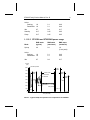
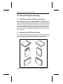
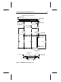
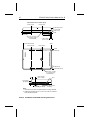
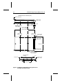
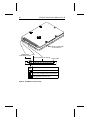
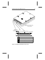
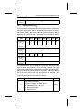
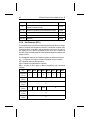
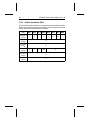
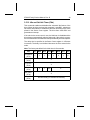
..................................... ST9235 Family: ..................................... ST9080A, ST9145A, ST9145AG ..................................... ST9235A, ST9235AG ..................................... AT Interface Drives ..................................... Product Manual ..................................... ST9235 Family Product Manual ST9080A, ST9145A,ST9145AG ST9235A, ST9235AG AT Interface Drives 36206-001, Rev. B 19 April 1993 1993 Seagate Technology, Inc. All rights reserved Publication Number: 36206-001, Rev. B Seagate®, Seagate Technology®, and the Seagate logo are registered trademarks of Seagate Technology, Inc. Other product names are registered trademarks or trademarks of their owners. Seagate reserves the right to change, without notice, product offerings or specifications. No part of this publication may be reproduced in any form without written permission of Seagate Technology, Inc. ST9235 Family Product Manual, Rev. B iii Contents 1.0 Drive specifications . . . . . . . . . . . . . . . . . . . . . . 1 1.1 Formatted capacity . . . . . . . . . . . . . . . . . . . . . 1 1.2 Physical organization . . . . . . . . . . . . . . . . . . . . 1 1.3 Logical organization . . . . . . . . . . . . . . . . . . . . . 1 1.4 Default logical geometry . . . . . . . . . . . . . . . . . . . 2 1.5 Functional specifications . . . . . . . . . . . . . . . . . . 2 1.6 Physical dimensions . . . . . . . . . . . . . . . . . . . . 3 1.7 Seek time . . . . . . . . . . . . . . . . . . . . . . . . . . 3 1.8 Spinup times (typical) . . . . . . . . . . . . . . . . . . . . 4 1.9 Reliability . . . . . . . . . . . . . . . . . . . . . . . . . . 4 1.10 Environment . . . . . . . . . . . . . . . . . . . . . . . . 4 1.10.1 Acoustics . . . . . . . . . . . . . . . . . . . . . . . 4 1.10.2 Ambient temperature . . . . . . . . . . . . . . . . . 4 1.10.3 Temperature gradient . . . . . . . . . . . . . . . . . 4 1.10.4 Relative humidity . . . . . . . . . . . . . . . . . . . 5 1.10.5 Altitude . . . . . . . . . . . . . . . . . . . . . . . . 5 1.10.6 Shock . . . . . . . . . . . . . . . . . . . . . . . . . 5 1.10.7 Vibration . . . . . . . . . . . . . . . . . . . . . . . . 6 1.11 Power specifications . . . . . . . . . . . . . . . . . . . . 6 1.11.1 Power management modes . . . . . . . . . . . . . . 6 1.11.2 Power usage . . . . . . . . . . . . . . . . . . . . . 8 1.11.3 Input power noise . . . . . . . . . . . . . . . . . . . 11 1.12 UL/CSA listing . . . . . . . . . . . . . . . . . . . . . . . 11 1.13 FCC verification . . . . . . . . . . . . . . . . . . . . . . 11 2.0 Drive handling and mounting . . . . . . . . . . . . . . . . 13 2.1 Handling and static-discharge precautions . . . . . . . . . 13 2.2 Mounting the ST9235 family drives . . . . . . . . . . . . . 13 iv ST9235 Family Product Manual, Rev. B 3.0 ATA interface . . . . . . . . . . . . . . . . . . . . . . . . 19 3.1 Drive configuration . . . . . . . . . . . . . . . . . . . . . 19 3.1.1 Master/slave selection . . . . . . . . . . . . . . . . 19 3.1.2 Remote LED . . . . . . . . . . . . . . . . . . . . . 19 3.1.3 Onboard drive diagnostics . . . . . . . . . . . . . . 23 3.2 ATA bus signal levels . . . . . . . . . . . . . . . . . . . 23 3.3 ATA interface cable . . . . . . . . . . . . . . . . . . . . 23 3.4 ATA interface connector . . . . . . . . . . . . . . . . . . 23 3.4.1 ATA interface connector pin assignments . . . . . . 25 3.5 ATA interface command description . . . . . . . . . . . . 26 3.5.1 Standby Immediate (E0H / 94H) . . . . . . . . . . . . 27 3.5.2 Idle Immediate (E1H / 95H / F8H) . . . . . . . . . . . 28 3.5.3 Standby (E2H / 96H ) . . . . . . . . . . . . . . . . . 29 3.5.4 Idle (E3H / 97H ) . . . . . . . . . . . . . . . . . . . 31 3.5.5 Check Power Mode (E5H / 98H ) . . . . . . . . . . . 32 3.5.6 Set Sleep Mode (E6H / 99H) . . . . . . . . . . . . . 33 3.5.7 Identify Drive (ECH) . . . . . . . . . . . . . . . . . . 34 3.5.8 Set Features (EFH) . . . . . . . . . . . . . . . . . . 36 3.5.9 Active Immediate (F9H) . . . . . . . . . . . . . . . . 37 3.5.10 Idle and Set Idle Timer (FAH) . . . . . . . . . . . . 38 3.5.11 Active and Set Idle Timer (FBH) . . . . . . . . . . . 39 3.5.12 Check Idle Mode (FDH) . . . . . . . . . . . . . . . 40 ST9235 Family Product Manual, Rev. B v Figures Figure 1. Typical startup and operation current profile for the ST9080A . . . . . . . . . . . . . . . . . . . . . . . 9 Figure 2. Typical startup and operation current profile for the ST9145A and the ST9145AG . . . . . . . . . . . . 10 Figure 3. Typical startup and operation current profile for the ST9235A and the ST9235AG . . . . . . . . . . . . 10 Figure 4. Acceptable mounting orientations for the ST9235 family drives . . . . . . . . . . . . . . . . . . . . . . . . . . . 13 Figure 5. ST9080A mounting dimensions . . . . . . . . . . . . . . 15 Figure 6. ST9145A and ST9145AG mounting dimensions . . . . . 16 Figure 7. ST9235A and ST9235AG mounting dimensions (MCC mounting version) . . . . . . . . . . . . . . . . . 17 Figure 8. ST9235A and ST9235AG mounting dimensions (non-MCC mounting version) . . . . . . . . . . . . . . . 18 Figure 9. ST9080A connector setup . . . . . . . . . . . . . . . . 20 Figure 10. ST9145A and ST9145AG connector setup . . . . . . . 21 Figure 11. ST9235A and ST9235AG connector setup . . . . . . . 22 Figure 12. ATA interface connector diagram . . . . . . . . . . . . 24 Figure 13. ATA interface signal summary . . . . . . . . . . . . . 25 ST9235 Family Product Manual, Rev. B 1 1.0 Drive specifications 1.1 Formatted capacity ST9080A ST9145A ST9145AG ST9235A ST9235AG Guaranteed Mbytes 64.0 127.9 209.7 Guaranteed sectors 125,096 249,900 409,760 Bytes per sector 512 512 512 ST9080A ST9145A ST9145AG ST9235A ST9235AG Read/Write heads 2 4 6 Discs 1 2 3 1.2 Physical organization 1.3 Logical organization The ST9235 family drives support all head, cylinder, and sector geometries, subject to the maximums specified below, and to the following condition: (sectors) × (heads) × (cylinders) ≤ total sectors per drive Sectors per track (max) 63 Read/Write heads (max) 15 Cylinders (max) Unrestricted 2 ST9235 Family Product Manual, Rev. B 1.4 Default logical geometry ST9080A ST9145A ST9145AG ST9235A ST9235AG Sectors per track 38 17 32 Read/Write heads 4 15 13 Cylinders 823 980 985 ST9080A ST9145A ST9145AG ST9235A ST9235AG Interface ATA ATA ATA Recording method RLL (2,7) RLL (2,7) RLL (2,7) Recording density (BPI) 45,500 45,600 45,500 Flux density (FCI) 30,300 30,400 30,300 Track density (TPI) 2,650 2,650 2,750 Spindle speed (RPM ± 0.5%) 3,449 3,449 3,449 Internal data transfer rate (Mbits per sec max—ZBR) 16 16 16 I/O data transfer rate (Mbits per sec max—ZBR) 4 4 4 Interleave 1:1 1:1 1:1 Cache buffer (Kbytes) 32 64 64 1.5 Functional specifications ST9235 Family Product Manual, Rev. B 3 1.6 Physical dimensions ST9080A ST9145A ST9145AG ST9235A ST9235AG Height (max) inches (mm) 0.49 (12.50) 0.75 (19.05) 0.75 (19.05) Width (max) inches (mm) 2.76 (70.10) 2.76 (70.10) 2.76 (70.10) Depth (max) inches (mm) 4.01 (101.85) 4.01 (101.85) 4.01 (101.85) Weight (max) ounces (kg) 4.80 (0.136) 6.50 (0.185) 7.25 (0.210) 1.7 Seek time Seek time is a true statistical average (at least 5,000 measurements) of seek time, less controller overhead. All measurements are made with nominal power at sea level and 25°C ambient temperature. Track-totrack seek time is an average of all possible single-track seeks in both directions. Average seek time is measured by executing seek commands between random sector addresses. Full-stroke seek time is one-half the time needed to seek from the first data sector to the maximum data sector and back to the first sector. Host overhead varies between systems and cannot be specified. Seek times for the ST9235 family drives are: Track-to-track typical (msec) maximum (msec) 5 8 Average typical (msec) maximum (msec) 16 19 Full-stroke typical (msec) maximum (msec) 27 30 Average latency (msec) 8.7 4 ST9235 Family Product Manual, Rev. B 1.8 Spinup times (typical) Power-on to Ready (sec) 4 Standby to Ready (sec) 2 1.9 Reliability Nonrecoverable read errors 1 per 1013 bits read Mean time between failures 150,000 power-on hours (nominal power, at sea level, 25°C ambient temperature) Preventative maintenance Not required Mean time to repair 10 minutes Service life 5 years 1.10 Environment 1.10.1 Acoustics ST9080A, ST9145A and ST9145AG: 30 dBA maximum (sound pressure) in Idle mode at 1 meter. ST9235A and ST9235AG: 33 dBA maximum (sound pressure) in Idle mode at 1 meter. 1.10.2 Ambient temperature Operating 5° to 55°C (41° to 131°F) Nonoperating –40° to 70°C (–40° to 158°F) 1.10.3 Temperature gradient Operating 30°C / hr (54°F / hr) max, without condensation Nonoperating 30°C / hr (54°F / hr) max, without condensation ST9235 Family Product Manual, Rev. B 5 1.10.4 Relative humidity Operating 8% to 80% noncondensing Nonoperating 8% to 90% noncondensing Transit (as packaged from factory) 5% to 95% noncondensing Maximum wet bulb temperature 26°C (78.8°F) 1.10.5 Altitude Operating –1,000 ft to 10,000 ft (–304.8 m to 3,048 m) Nonoperating –1,000 ft to 40,000 ft (–304.8 m to 12,192 m) 1.10.6 Shock All shock specifications assume that the drive is mounted in an approved orientation with the input levels at the drive mounting screws. Operating shock specifications vary between the “A” and “AG” drives, as described below. The nonoperating specifications assume that the read/write heads are positioned in the shipping zone. Note. At power-down, the read/write heads automatically move to the shipping zone. The head and slider assembly park inside of the maximum data cylinder. When power is applied, the heads recalibrate to Track 0. 1.10.6.1 Operating shock The maximum shock the ST9080A, ST9145A and ST9235A can experience during operation without incurring nonrecoverable data errors is 2 Gs; the maximum operating shock they can experience without damage to the drive is 10 Gs (based on half sine-wave shock pulses of 11 msec). The ST9145AG and ST9235AG, with their SafeRite components, can experience a maximum operating shock of 100 Gs without nonrecoverable data errors (based on half-sine shock pulses of 2 through 11 msec). 1.10.6.2 Nonoperating shock The maximum nonoperating shock that ST9235 family drives can experience without incurring physical damage or degradation in performance when the drive is subsequently put into operation is 150 Gs (based on half-sine shock pulses of 11 msec). 6 ST9235 Family Product Manual, Rev. B 1.10.7 Vibration All vibration specifications assume that the drive is mounted in an approved orientation with the input levels at the drive mounting screws. The nonoperating specifications assume that the read/write heads are positioned in the shipping zone. 1.10.7.1 Operating vibration The following table lists maximum vibration levels that ST9235 family drives may experience without incurring physical damage or degraded performance. 5–22 Hz 0.020-inch displacement (double amplitude) 22–400* Hz 0.5 Gs acceleration (peak) 400*–22 Hz 0.5 Gs acceleration (peak) 22–5 Hz 0.020-inch displacement (double amplitude) *500 Hz typical 1.10.7.2 Nonoperating vibration The maximum nonoperating vibration that the ST9235 family drives can experience without incurring physical damage or degradation in performance when the drive is subsequently put into operation: 5–22 Hz 0.162-inch displacement (double amplitude) 22–500 Hz 4 Gs acceleration (peak) 500–22 Hz 4 Gs acceleration (peak) 22–5 Hz 0.162-inch displacement (double amplitude) 1.11 Power specifications ST9235 family drives receive DC power (+5V) through pin 41 and pin 42 of the ATA interface connector; pin 43 is the ground. ST9235 Family Product Manual, Rev. B 7 1.11.1 Power management modes Power management is required for low-power portable systems. In most systems, you can control power management through the system setup program. The ST9235 family drives feature several power management modes, which are described briefly in the following paragraphs: Active mode. The drive is in Active mode during the read/write and seek operations. Idle-Ready mode. In Idle-Ready mode, the spindle is up to speed and the heads are on track at the last track accessed. The drive accepts all commands, and returns to Active mode when disc access is necessary. Idle mode. At power-on, the drive sets the idle timer to enter Idle mode after 5 seconds of inactivity (default setting). In Idle mode, the spindle remains up to speed. The heads are parked away from the data zones for maximum data safety. The buffer remains enabled, and the drive accepts all commands and returns to Active mode any time disc access is necessary. Standby mode. The drive enters Standby mode when the host sends a Standby Immediate command. If the standby timer has been set by the host system, the drive can also enter Standby mode automatically after the drive has been in Idle mode for a specifiable length of time. The standby timer delay is system dependent, and is usually established using the system setup utility. In Standby mode, the buffer remains enabled, the heads are parked and the spindle is at rest. The drive accepts all commands, and returns to Active mode any time disc access is necessary. Sleep mode. The drive enters Sleep mode when a Sleep Immediate command has been received from the host. The heads are parked and the spindle is at rest. The drive leaves Sleep mode when a Soft Reset or Hard Reset command is sent from the host. After a soft reset has been received, the drive exits Sleep mode and enters Standby mode with all current emulation and translation parameters intact. Following a hard reset, the drive returns to Active mode. Idle and Standby Timers. The drive sets the default time delay for the idle timer at power-on. In most systems, you can set this delay using the system setup utility. Each time the drive performs an Active function (read, write or seek), the idle timer is reinitialized, and begins the countdown from the specified delay time to zero. If the idle timer reaches zero before any drive activity is required, the drive makes a transition to Idle mode. The drive then begins the standby timer countdown, if the host has set the standby timer. If the host has not set the standby timer, the 8 ST9235 Family Product Manual, Rev. B drive remains in Idle mode. If the standby timer reaches zero before any drive activity is required, the drive makes a transition to Standby mode. In both Idle and Standby mode, the drive accepts all commands, and returns to Active mode when disc access is necessary. 1.11.2 Power usage Power requirements for the ST9235 family drives are listed below. Typical power measurements are taken at 5V and zero ripple on a 10 MHz AT system. Typical Active mode current and power specifications assume nominal voltages applied, 25°C ambient temperature at sea level, with the spindle rotating (two spindle rotations between each operation) and the drive in default logical geometry. Specification power maximums are measured at 5.25V. Maximum seek currents and power usage are measured on repetitive one-third-stroke buffered seeks with one-half spindle rotation between each seek. Maximum read/write currents and power are measured with one-half spindle rotation between each operation. Transient state changes may cause current peaks above the maximum levels. 1.11.2.1 ST9080A power usage Mode RMS watts (typical) RMS watts (maximum) RMS amps (maximum) Spinup 3.2 5.0 0.9 (2 sec peak) Active Seeking Read/Write 1.8 1.8 2.1 2.1 0.40 0.40 Idle 0.7 0.9 0.17 Standby 0.17 0.25 0.05 Sleep 0.17 0.25 0.05 1.11.2.2 ST9145A and ST9145AG power usage Mode RMS watts (typical) RMS watts (maximum) RMS amps (maximum) Spinup 3.9 5.6 1.0 (2 sec peak) ST9235 Family Product Manual, Rev. B 9 Active Seeking Read/Write 1.8 1.8 2.1 2.1 0.40 0.40 Idle 0.7 0.9 0.17 Standby 0.17 0.25 0.05 Sleep 0.17 0.25 0.05 1.11.2.3 ST9235A and ST9235AG power usage Mode RMS watts (typical) RMS watts (maximum) RMS amps (maximum) Spinup 4.6 5.6 1.0 (2 sec peak) Active Seeking Read/Write 1.8 1.8 2.1 2.1 0.40 0.40 Idle 0.7 0.9 0.17 Current (mA) Start spindle 800 Idle mode 700 Active mode Upload code 600 Spindle brake First command auto calibrate 500 Standby mode 400 300 200 Ready Auto park 100 Spinup 0 0 1 2 3 4 5 6 7 8 Time (seconds) 9 10 11 12 13 14 15 Figure 1. Typical startup and operation current profile for the ST9080A 10 ST9235 Family Product Manual, Rev. B Current (mA) Ready Start spindle Idle mode Standby mode Spinup Active mode 800 Upload code Spindle brake 600 400 200 0 0 1 2 3 4 5 6 7 8 9 10 11 12 Time (seconds) Figure 2. Typical startup and operation current profile for the ST9145A and the ST9145AG Current (mA) Start spindle 1200 Idle mode Spinup 1000 Active mode Upload code Spindle brake 800 Standby mode 600 400 Ready 200 0 0 1 2 3 4 5 6 7 8 Time (seconds) 9 10 11 12 13 14 15 Figure 3. Typical startup and operation current profile for the ST9235A and the ST9235AG ST9235 Family Product Manual, Rev. B 11 Standby 0.17 0.25 0.05 Sleep 0.17 0.25 0.05 1.11.2.4 Current profiles Current profiles for the ST9235 family drives are shown in Figures 1, 2 and 3 on pages 9 and 10. 1.11.3 Input power noise Voltage tolerance (including ripple): + 5%, – 10% Maximum permitted input noise ripple: 150 mV (peak-to-peak) Maximum permitted input noise: 10 MHz 1.12 UL/CSA listing The ST9235 family drives are listed in accordance with UL 1950 and CSA C22.2 (950-M89), and meet all applicable sections of IEC 380, IEC 435, IEC 950, VDE 0806/08.81 and EN 60950 as tested by TUV-Rheinland, North America. 1.13 FCC verification The ST9235 family drives are intended to be contained solely within a personal computer or similar enclosure (not attached to an external device). As such, the drive is considered to be a subassembly even when it is individually marketed to the customer. As a subassembly, no Federal Communications Commission verification or certification of the device is required. Seagate Technology, Inc. has tested this device in enclosures as described above to ensure that the total assembly (enclosure, disc drive, motherboard, power supply, etc.) does comply with the limits for a Class B computing device, pursuant to Subpart J, Part 15 of the FCC rules. Operation with noncertified assemblies is likely to result in interference to radio and television reception. Radio and Television Interference. This equipment generates and uses radio frequency energy and if not installed and used in strict accordance with the manufacturer’s instructions, may cause interference to radio and television reception. 12 ST9235 Family Product Manual, Rev. B This equipment is designed to provide reasonable protection against such interference in a residential installation. However, there is no guarantee that interference will not occur in a particular installation. If this equipment does cause interference to radio or television, which can be determined by turning the equipment on and off, you are encouraged to try one or more of the following corrective measures: • Reorient the receiving antenna. • Move the device to one side or the other of the radio or TV. • Move the device farther away from the radio or TV. • Plug the computer into a different outlet so that the receiver and computer are on different branch outlets. If necessary you should consult your dealer or an experienced radio/television technician for additional suggestions. You may find helpful the following booklet prepared by the Federal Communications Commission: How to Identify and Resolve Radio-Television Interference Problems. This booklet is available from the Superintendent of Documents, U.S. Government Printing Office, Washington, DC 20402. Refer to publication number 004-000-00345-4. ST9235 Family Product Manual, Rev. B 13 2.0 Drive handling and mounting 2.1 Handling and static-discharge precautions After unpacking, and prior to system integration, the drive may be exposed to potential handling and ESD hazards. It is mandatory that you observe standard static-discharge precautions. A grounded wrist-strap is preferred. Handle the drive only by the sides of the head/disc assembly. Avoid contact with the printed circuit board, all electronic components and the interface connector. Do not apply pressure to the top cover. Always rest the drive on a padded antistatic surface until you mount it in the host system. 2.2 Mounting the ST9235 family drives You can mount ST9235 family drives in any of the approved orientations shown in Figure 4. Allow a minimum clearance of 0.030 inches (0.762 mm) around the entire perimeter of the drive for cooling airflow. Figure 4. Acceptable mounting orientations for the ST9235 family drives 14 ST9235 Family Product Manual, Rev. B Figures 5 through 8 on pages 15 through 18 provide mounting dimensions for the ST9235 family drives. Some ST9235A and ST9235AG drives and all ST9145A and ST9145AG drives are designed in accordance with the industry-standard MCC direct-mounting specifications. These drives have slightly different mounting dimensions from non-MCC drives, and require the use of MCC-compatible connectors in fixed mounting applications. Caution. To avoid damaging the drive: • Use M3X0.5 metric mounting screws only. • Do not insert mounting screws more than 0.150 inches (3.81 mm) into the mounting holes. • Do not overtighten the screws (maximum torque: 3 inch-lb). ST9235 Family Product Manual, Rev. B 15 Dimensions are in inches (mm) 0.492 ± 0.005 (12.50 ± 0.13) 0.066 ± 0.020 (1.68 ± 0.51) 0.000 0.100 ± 0.010 (2.54 ± 0.25) 0.152 ± 0.005 (3.86 ± 0.13) 4X 3 mm × 0.5 mm 0.15 in (3.81 mm) min full thread 1.227 ± 0.025 (31.17 ± 0.64) 4.010 (101.85) max 1.500 ± 0.010 (38.10 ± 0.25) 0.000 1.375 ± 0.015 (34.93 ± 0.38) 0.155 ± 0.025 (3.94 ± 0.64) 0.000 0.275 ± 0.025 (6.99 ± 0.64) 2.760 (70.10) max 2.430 ± 0.020 (61.72 ± 0.51) 4X 3 mm × 0.5 mm 0.15 in (3.81 mm) min full thread Pin 20 removed for keying Pin 1 0.166 ± 0.015 (4.22 ± 0.38) 0.079 (2.00) 0.079 (2.00) 1.654 (42.00) Figure 5. ST9080A mounting dimensions 16 ST9235 Family Product Manual, Rev. B Dimensions are in inches (mm) 2.875 (73.03) 1.375 (34.93) 0.750 max (19.05) 0.157 ± 0.020 (3.99 ± 0.51) 0.000 0.118 (3.00) 4X 3 mm × 0.5 mm, 0.15 in (3.81 mm) min full thread 1.227 ± 0.025 (31.17 ± 0.64) 0.152 ± 0.005 (3.86 ± 0.13) 4.010 max (101.85) 2.875 (73.03) 0.000 1.375 (34.93) 0.000 0.160 (4.06) 2.590 (65.79) 2.760 max (70.10) 4X 3 mm × 0.5 mm, 0.15 in (3.81 mm) min full thread 0.394 ± 0.025 (10.01 ± 0.64) Pin 1 0.079 (2.00) pin spacing 0.079 (2.00) pin spacing Pin 20 removed for keying Notes: 1. The ST9145A form-factor complies with MCC mounting standards. 2. All dimensional tolerances are ± 0.010 inch (± 0.25 mm) maximum unless otherwise specified. Figure 6. ST9145A and ST9145AG mounting dimensions ST9235 Family Product Manual, Rev. B 17 Dimensions are in inches (mm) 0.750 (19.05) max 0.118 ± 0.010 (3.00 ± 0.25) 0.000 4X 3 mm × 0.5 mm 0.15 in. (3.81 mm) min full thread 0.152 ± 0.005 (3.86 ± 0.13) 1.227 ± 0.025 (31.17 ± 0.64) 4.010 (101.85) max 1.500 ± 0.010 (38.10 ± 0.25) 0.000 1.375 ± 0.015 (34.93 ± 0.38) 0.155 ± 0.025 (3.94 ± 0.64) 0.000 0.239 ± 0.025 (6.07 ± 0.64) 2.760 (70.10) max 2.430 ± 0.020 (61.72 ± 0.51) 4X 3 mm × 0.5 mm 0.15 in (3.81 mm) min full thread Pin 20 removed for keying Pin 1 0.157 ± 0.009 (3.99 ± 0.23) 0.079 (2.00) 0.079 (2.00) 1.654 (42.00) Figure 7. ST9235A and ST9235AG mounting dimensions (MCC mounting version) 18 ST9235 Family Product Manual, Rev. B Dimensions are in inches (mm) 0.750 (19.05) max 0.230 ± 0.010 (5.84 ± 0.25) 0.000 0.152 ± 0.005 (3.86 ± 0.13) 4X 3 mm × 0.5 mm 0.15 in. (3.81 mm) min full thread 1.227 ± 0.025 (31.17 ± 0.64) 4.010 (101.85) max 1.500 ± 0.010 (38.10 ± 0.25) 0.000 1.375 ± 0.015 (34.93 ± 0.38) 0.155 ± 0.025 (3.94 ± 0.64) 0.000 0.275 ± 0.025 (6.99 ± 0.64) 2.760 (70.10) max 2.430 ± 0.020 (61.72 ± 0.51) 4X 3 mm × 0.5 mm 0.15 in (3.81 mm) min full thread Pin 20 removed for keying Pin 1 0.166 ± 0.015 (4.22 ± 0.38) 0.079 (2.00) 0.079 (2.00) 1.654 (42.00) Figure 8. ST9235A and ST9235AG mounting dimensions (non-MCC mounting version) ST9235 Family Product Manual, Rev. B 19 3.0 ATA interface The ST9235 family drives use the industry-standard ATA task file interface. The drives support both 8-bit and 16-bit data transfers and have no DMA capability. All data transfers are done through programmed I/O. Refer to the Seagate ATA Interface Specification, publication number 36111-001. Up to two drives can be daisy-chained (assigning master and slave drives) on the same host bus. 3.1 Drive configuration 3.1.1 Master/slave selection A master/slave relationship must be established between drives on the AT bus using the drive jumpers. Drive 1 is configured as the master and Drive 2 is configured as the slave. Refer to the table below and Figures 9 through 11 on pages 20 through 22 for user-configuration jumper settings to configure a drive as a master or a slave. Jumper for pins A and B Jumper for pins C and D Configuration Removed Removed Drive is master; no slave drive present Removed Installed Drive is master; Seagate slave drive present Installed Removed Drive is slave; Seagate master drive present Installed Installed Reserved position—do not use 3.1.2 Remote LED The drive indicates activity to the host through the DASP– line (pin 39) on the ATA interface. This line may be connected to a drive status indicator driving an LED at 5V. The line has a 30 mA nominal current limit. 20 ST9235 Family Product Manual, Rev. B Note. Drive is shown with circuit board up. Master/slave Pin 1 configuration jumpers Pin 20 removed for keying Circuit board B A D C Drive is master; no slave present Drive is master; Seagate slave drive present Drive is slave; Seagate master drive present Reserved positions (do not use) Figure 9. ST9080A connector setup ST9235 Family Product Manual, Rev. B 21 Note. Drive is shown with circuit board up. Master/slave Pin 1 configuration jumpers Pin 20 removed for keying Circuit board B A D C Drive is master; no slave present Drive is master; Seagate slave drive present Drive is slave; Seagate master drive present Reserved positions (do not use) Figure 10. ST9145A and ST9145AG connector setup 22 ST9235 Family Product Manual, Rev. B Note. Drive is shown with circuit board up. Master/slave Pin 1 configuration jumpers Pin 20 removed for keying Circuit board B A D C Drive is master; no slave present Drive is master; Seagate slave drive present Drive is slave; Seagate master drive present Reserved positions (do not use) Figure 11. ST9235A and ST9235AG connector setup ST9235 Family Product Manual, Rev. B 3.1.3 23 Onboard drive diagnostics At power-on, the drive executes a series of diagnostic tests. A series of LED flashes on the system panel indicates a failure. Error codes (LED flashes) Drive error condition 1 Microprocessor error 2 ROM checksum error 3 ATA interface chip failure 5 External RAM error 6 Buffer RAM error 3.2 ATA bus signal levels Signals driven by the drive have the following output characteristics at the drive connector: Logic Low 0.0V to 0.4V Logic High 2.5V to 5.25V Signals received by the drive must have the following input characteristics, measured at the drive connector: Logic Low 0.0V to 0.8V Logic High 2.0V to 5.25V 3.3 ATA interface cable Maximum cable length is 18 inches (457 mm). It is recommended that the connectors be keyed by inserting a plug into the pin-20 location of the female interface connector. 3.4 ATA interface connector The drive connector is a 44-conductor connector with 2 rows of 22 male pins on 0.079-inch (2 mm) centers (see Figure 12 on page 24). The mating cable connector is a 44-conductor, nonshielded connector with 2 rows of 22 female contacts on 0.079-inch (2 mm) centers. It is recommended that the connectors be keyed by inserting a plug into the pin 20 location of each interface connector. Strain relief is recommended. 24 ST9235 Family Product Manual, Rev. B Some ST9235A and ST9235AG drives and all ST9145A and ST9145AG drives are designed to support the industry-standard MCC direct-mounting specifications. When installing MCC-compatible drives in fixed mounting applications, be sure to use MCC-compatible connectors, such as Molex part number 87368-442x. For applications involving flexible cables or printed circuit cables (PCCs), use Molex part number 872594413 or equivalent to connect the drive to the system. Select a connector that provides adequate clearance for the master/slave configuration jumpers if the application requires the use of such jumpers. 0.079 ± 0.003 0.020 ± 0.002 sq. typ. drive circuit board Do not scale 0.079 ± 0.003 44 signal/power pins (22 rows) 1.654 Configuration jumpers (2 rows) 0.158 ± 0.003 0.152 ± 0.005 Figure 12. ATA interface connector diagram Note. Tolerances are noncumulative over entire range ST9235 Family Product Manual, Rev. B 3.4.1 25 ATA interface connector pin assignments Figure 13 shows the pin assignments for the standard ATA interface connector and summarizes the ATA interface signals used by the drive. For an explanation of these signals, see the Seagate ATA Interface Specification, publication number 36111-001. Drive pin # 1 2 3 4 5 6 7 8 9 10 11 12 13 14 15 16 17 18 19 20 21 22 23 24 25 26 27 28 29 30 31 32 33 34 35 36 37 38 39 40 41 42 43 44 Signal name Host pin # and signal description Reset– Ground DD7 DD8 DD6 DD9 DD5 DD10 DD4 DD11 DD3 DD12 DD2 DD13 DD1 DD14 DD0 DD15 Ground (removed) Reserved Ground DIOW– Ground DIOR– Ground Reserved Reserved Reserved Ground INTRQ IOCS16– DA1 PDIAG– DA0 DA2 CS1FX– CS3FX– DASP– Ground Power Power Ground Reserved Figure 13. ATA interface signal summary 1 2 3 4 5 6 7 8 9 10 11 12 13 14 15 16 17 18 19 20 21 22 23 24 25 26 27 28 29 30 31 32 33 34 35 36 37 38 39 40 41 42 43 44 Host Reset Ground Host Data Bus Bit 7 Host Data Bus Bit 8 Host Data Bus Bit 6 Host Data Bus Bit 9 Host Data Bus Bit 5 Host Data Bus Bit 10 Host Data Bus Bit 4 Host Data Bus Bit 11 Host Data Bus Bit 3 Host Data Bus Bit 12 Host Data Bus Bit 2 Host Data Bus Bit 13 Host Data Bus Bit 1 Host Data Bus Bit 14 Host Data Bus Bit 0 Host Data Bus Bit 15 Ground (No Pin) Reserved Ground Host I/O Write Ground Host I/O Read Ground Reserved Reserved Reserved Ground Host Interrupt Request Host 16 Bit I/O Host Address Bus Bit 1 Passed Diagnostics Host Address Bus Bit 0 Host Address Bus Bit 2 Host Chip Select 0 Host Chip Select 1 Drive Active / Slave Present Ground +5V (logic) +5V (motor) Ground for power pins Reserved 26 ST9235 Family Product Manual, Rev. B 3.5 ATA interface command description The commands listed on the following pages are specific to the ST9235 family drives. For a description of any ATA interface commands not found in this manual and Seagate’s implementation of the ATA interface, refer to the ATA Interface Specification, Seagate publication number 36111001. In some cases, there may be two opcodes for a single command. In such instances, both opcodes perform in an equivalent manner and are treated identically by the drive. In all of the following tables, D/S designates the drive select bit and an “X” designates that the register is not used for the particular command. Notations for special register functions are listed in the command table and explained in the command descriptions. ST9235 Family Product Manual, Rev. B 3.5.1 27 Standby Immediate (E0H / 94H) When the drive receives this command, it enters Standby mode immediately. The drive sets BSY, initiates a shutdown sequence, enters Standby mode, clears BSY, and generates an interrupt. If the drive is already in Standby mode when this command is received, it sets BSY, clears BSY and generates an interrupt. E0H Bit 7 Bit 6 Bit 5 Bit 4 Bit 3 Bit 2 Bit 1 Bit 0 Command (1F7H) 1 1 1 0 0 0 0 0 Cyl. High (1F5H) X Cyl. Low (1F4H) X Drv. Head (1F6H) 1 0 1 D/S X Sec. Num. (1F3H) X Sec. Cnt. (1F2H) X 94H Bit 7 Bit 6 Bit 5 Bit 4 Bit 3 Bit 2 Bit 1 Bit 0 Command (1F7H) 1 0 0 1 0 1 0 0 Cyl. High (1F5H) X Cyl. Low (1F4H) X Drv. Head (1F6H) 1 0 1 D/S X Sec. Num. (1F3H) X Sec. Cnt. (1F2H) X 28 ST9235 Family Product Manual, Rev. B 3.5.2 Idle Immediate (E1H / 95H / F8H) When the drive receives this command, it sets BSY and enters Idle mode. If the drive is in Standby mode, the spinup routine is executed. If the drive is in either Active or Idle mode, the spindle is already up to speed, and the spinup routine is skipped. Next, the drive clears BSY and generates an interrupt. E1H Bit 7 Bit 6 Bit 5 Bit 4 Bit 3 Bit 2 Bit 1 Bit 0 Command (1F7H) 1 1 1 0 0 0 0 1 Cyl. High (1F5H) X Cyl. Low (1F4H) X Drv. Head (1F6H) 1 0 1 D/S X Sec. Num. (1F3H) X Sec. Cnt. (1F2H) X 95H Bit 7 Bit 6 Bit 5 Bit 4 Bit 3 Bit 2 Bit 1 Bit 0 Command (1F7H) 1 0 0 1 0 1 0 1 Cyl. High (1F5H) X Cyl. Low (1F4H) X Drv. Head (1F6H) 1 0 1 D/S X Sec. Num. (1F3H) X Sec. Cnt. (1F2H) X ST9235 Family Product Manual, Rev. B 29 F8H Bit 7 Bit 6 Bit 5 Bit 4 Bit 3 Bit 2 Bit 1 Bit 0 Command (1F7H) 1 1 1 1 1 0 0 0 Cyl. High (1F5H) X Cyl. Low (1F4H) X Drv. Head (1F6H) 1 0 1 D/S X Sec. Num. (1F3H) X Sec. Cnt. (1F2H) X 3.5.3 Standby (E2H / 96H ) When the drive receives this command, it sets BSY and makes a transition to Standby mode. Depending on the value placed in the Sector Count register, the drive either enables or disables the standby timer. The drive then clears BSY and generates an interrupt. Placing a zero value in the Sector Count register disables the standby timer. Placing a nonzero value in the Sector Count register enables the standby timer to count down in 5-second increments. A value of 12 sets the standby timer for sixty seconds before the standby routine is initiated. A value of 13 sets the timer for sixty-five seconds. The minimum amount of time allowed for the standby timer is sixty seconds. Consequently, all values from 1−11 have an equivalent effect to a value of 12 for the standby timer. The delay timer is reinitialized by the drive whenever the drive enters Active mode. If the drive is already in Standby mode, this command has no effect. The default power-on condition for this drive is that the standby timer is disabled. 30 ST9235 Family Product Manual, Rev. B E2H Bit 7 Bit 6 Bit 5 Bit 4 Bit 3 Bit 2 Bit 1 Bit 0 Command (1F7H) 1 1 1 0 0 0 1 0 Cyl. High (1F5H) X Cyl. Low (1F4H) X Drv. Head (1F6H) 1 0 1 D/S X Sec. Num. (1F3H) X Sec. Cnt. (1F2H) standby timer delay (in 5-second increments) 96H Bit 7 Bit 6 Bit 5 Bit 4 Bit 3 Bit 2 Bit 1 Bit 0 Command (1F7H) 1 0 0 1 0 1 1 0 Cyl. High (1F5H) X Cyl. Low (1F4H) X Drv. Head (1F6H) 1 0 1 D/S X Sec. Num. (1F3H) X Sec. Cnt. (1F2H) standby timer delay (in 5-second increments) ST9235 Family Product Manual, Rev. B 3.5.4 31 Idle (E3H / 97H ) When the drive receives this command, it sets BSY, makes a transition to Idle mode, sets the standby timer if necessary, clears BSY and generates an interrupt. The minimum amount of time allowed for the standby timer is sixty seconds. Consequently, all values from 1−11 have an equivalent effect to a value of 12 for the standby timer. E3H Bit 7 Bit 6 Bit 5 Bit 4 Bit 3 Bit 2 Bit 1 Bit 0 Command (1F7H) 1 1 1 0 0 0 1 1 Cyl. High (1F5H) X Cyl. Low (1F4H) X Drv. Head (1F6H) 1 0 1 D/S X Sec. Num. (1F3H) X Sec. Cnt. (1F2H) standby timer delay (in 5-second increments) 97H Bit 7 Bit 6 Bit 5 Bit 4 Bit 3 Bit 2 Bit 1 Bit 0 Command (1F7H) 1 0 0 1 0 1 1 1 Cyl. High (1F5H) X Cyl. Low (1F4H) X Drv. Head (1F6H) 1 0 1 D/S X Sec. Num. (1F3H) X Sec. Cnt. (1F2H) idle timer delay (in 5-second increments) 32 ST9235 Family Product Manual, Rev. B 3.5.5 Check Power Mode (E5H / 98H ) This command returns a code for the power mode the drive is currently in or making a transition to. When the drive receives this command, it sets BSY, returns a value representing the current mode through the Sector Count register, clears BSY and generates an interrupt. The return values are as follows: 00H = The drive is in, or entering, Standby mode. FFH = The drive is in, or entering, either Idle or Active mode. E5H Bit 7 Bit 6 Bit 5 Bit 4 Bit 3 Bit 2 Bit 1 Bit 0 Command (1F7H) 1 1 1 0 0 1 0 1 Cyl. High (1F5H) X Cyl. Low (1F4H) X Drv. Head (1F6H) 1 0 1 D/S X Sec. Num. (1F3H) X Sec. Cnt. (1F2H) X 98H Bit 7 Bit 6 Bit 5 Bit 4 Bit 3 Bit 2 Bit 1 Bit 0 Command (1F7H) 1 0 0 1 1 0 0 0 Cyl. High (1F5H) X Cyl. Low (1F4H) X Drv. Head (1F6H) 1 0 1 D/S X Sec. Num. (1F3H) X Sec. Cnt. (1F2H) X ST9235 Family Product Manual, Rev. B 3.5.6 33 Set Sleep Mode (E6H / 99H) This command tells the drive to enter Sleep mode immediately. When the drive receives this command, it sets BSY, enters Sleep mode, clears BSY and generates an interrupt. When a soft reset is sent from the host, the drive leaves Sleep mode and makes a transition to Standby mode. After a soft reset has been received, the drive exits Sleep mode and makes a transition to Standby mode with all emulation and translation parameters intact. After a hard reset has been received, the drive returns to Active mode. E6H Bit 7 Bit 6 Bit 5 Bit 4 Bit 3 Bit 2 Bit 1 Bit 0 Command (1F7H) 1 1 1 0 0 1 1 0 Cyl. High (1F5H) X Cyl. Low (1F4H) X Drv. Head (1F6H) 1 0 1 D/S X Sec. Num. (1F3H) X Sec. Cnt. (1F2H) X 99H Bit 7 Bit 6 Bit 5 Bit 4 Bit 3 Bit 2 Bit 1 Bit 0 Command (1F7H) 1 0 0 1 1 0 0 1 Cyl. High (1F5H) X Cyl. Low (1F4H) X Drv. Head (1F6H) Sec. Num. (1F3H) 1 0 1 D/S X X 34 ST9235 Family Product Manual, Rev. B Sec. Cnt. (1F2H) 3.5.7 X Identify Drive (ECH) This command is accepted by ROM during system startup. ROM clears the BUSY status within 100 nsec from power-on, but does not indicate the DRIVE READY status until after the upload of external RAM is complete. This command can be executed before the DRIVE READY status has been asserted. ECH Bit 7 Bit 6 Bit 5 Bit 4 Bit 3 Bit 2 Bit 1 Bit 0 Command (1F7H) 1 1 1 0 1 1 0 0 Cyl. High (1F5H) X Cyl. Low (1F4H) X Drv. Head (1F6H) 1 0 1 D/S X Sec. Num. (1F3H) X Sec. Cnt. (1F2H) X The implementation of this command is compatible with the Seagate ATA Interface specifications. This command causes 512 bytes (256 words) of information to be returned to the host (see table below). When the command is received, the drive sets BSY, stores the information in the sector buffer, sets DRQ, and generates an interrupt. In the following table, an x indicates a drive-specific value; most default values for the ST9235 family drives are listed in Section 1. Word 0 Description Configuration Information: Bit 10: Disc Transfer ≤ 10 Mbits per sec Bit 6: Fixed Drive Bit 4: Head switch time > 15 µsec Bit 3: Not MFM encoded Bit 1: Hard Sectored Value 045AH ST9235 Family Product Manual, Rev. B Word Description 35 Value 1 Number fixed cylinders: (default logical emulation) xxxxH 2 Reserved 0000H 3 Number of heads: (default) 00xxH 4 Number of unformatted bytes per track xxxxH 5 Number of unformatted bytes per sector: 566 xxxxH 6 Number of sectors per track: (default logical emulation) 00xxH Reserved 0000H Serial number: (20 ASCII characters, 0000H = none) ASCII 20 Controller type = Dual-ported multisector buffer with caching 0003H 21 Buffer size 00xxH 22 Number of ECC bytes 000BH 23–26 Firmware revision (8 ASCII character string): xx = ROM ver., ss = RAM ver., tt = RAM ver. xx.ss.tt 27–46 Drive model number: (40 ASCII characters, padded to end of string) 7–9 10–19 ST9xxxx 47 Read Multiple command supported 0010H 48 Cannot perform double word I/O 0000H 49 Capabilities: DMA not supported 0000H 50 Reserved 0000H 51 Minimum PIO data transfer cycle time (410 nsec) 019AH 52 Minimum DMA transfer cycle time (not supported) 0000H 53 The fields in translation mode may be valid 0000H 54 Number of cylinders (current emulation mode) xxxxH 55 Number of heads (current emulation mode) xxxxH 36 ST9235 Family Product Manual, Rev. B Word Description 56 57–58 Value Number of sectors per track (current emulation mode) xxxxH Number of cylinders (current emulation mode) xxxxH 59–127 Reserved 0000H 128–159 Vendor unique 0000H 160–255 Reserved 0000H 3.5.8 Set Features (EFH) This command sets values for the features supported by the drive. When the drive receives this command, it sets BSY, checks the contents of the Features register, clears BSY, and generates an interrupt. If the value in the register is not a feature supported by the drive, the command is aborted. Power-on default has the read look-ahead feature enabled, and 4 bytes of ECC. The acceptable values in the Features register are defined as follows: 44H = 11 bytes of ECC apply on Read Long/Write Long commands. 55H = Disable read look-ahead feature. AAH = Enable look-ahead feature (default). BBH = 4 bytes of ECC apply on Read Long/Write Long commands (default). EFH Bit 7 Bit 6 Bit 5 Bit 4 Bit 3 Bit 2 Bit 1 Bit 0 Command (1F7H) 1 1 1 0 1 1 1 1 Cyl. High (1F5H) X Cyl. Low (1F4H) X Drv. Head (1F6H) 1 0 1 D/S X Sec. Num. (1F3H) X Sec. Cnt. (1F2H) X ST9235 Family Product Manual, Rev. B Features (1F1H) Set Features parameter 37 38 ST9235 Family Product Manual, Rev. B 3.5.9 Active Immediate (F9H) This command causes the drive to enter Active mode immediately. When the drive receives this command, it sets BSY, makes a transition to Active mode, clears BSY and generates an interrupt. F9H Bit 7 Bit 6 Bit 5 Bit 4 Bit 3 Bit 2 Bit 1 Bit 0 Command (1F7H) 1 1 1 1 1 0 0 1 Cyl. High (1F5H) X Cyl. Low (1F4H) X Drv. Head (1F6H) 1 0 1 D/S X Sec. Num. (1F3H) X Sec. Cnt. (1F2H) X ST9235 Family Product Manual, Rev. B 39 3.5.10 Idle and Set Idle Timer (FAH) This command enables and disables the automatic idle feature of the drive. When the drive receives this command, it sets BSY, switches to Idle mode, and enables or disables the idle timer according to the value placed in the Sector Count register. The drive then clears BSY and generates an interrupt. If the value in the sector count is zero, the idle timer is disabled and the drive does not automatically switch to Idle mode. If the value is not zero, the drive switches to Idle mode after the specified delay time has elapsed. The delay time is specified in the Sector Count register in 100-msec increments. The delay is reinitialized whenever the drive enters Active mode. Note. The factory-set default for the idle timer is five seconds. FAH Bit 7 Bit 6 Bit 5 Bit 4 Bit 3 Bit 2 Bit 1 Bit 0 Command (1F7H) 1 1 1 1 1 0 1 0 Cyl. High (1F5H) X Cyl. Low (1F4H) X Drv. Head (1F6H) 1 0 1 D/S X Sec. Num. (1F3H) X Sec. Cnt. (1F2H) idle timer delay (in 100-msec increments) 40 ST9235 Family Product Manual, Rev. B 3.5.11 Active and Set Idle Timer (FBH) This command enables and disables the automatic idle feature of the drive. When the drive receives this command, it sets BSY, switches to Active mode, and enables or disables the idle timer according to the value placed in the Sector Count register. The drive then clears BSY and generates an interrupt. If the value in the Sector Count register is zero, the idle timer is disabled and the drive does not automatically switch to Idle mode. If the value is not zero, the drive switches to Idle mode after the specified delay time has elapsed. The delay time is specified in the Sector Count register in 100-msec increments. The delay is reinitialized whenever the drive enters Active mode. Note. The factory-set default for the idle timer is five seconds. FBH Bit 7 Bit 6 Bit 5 Bit 4 Bit 3 Bit 2 Bit 1 Bit 0 Command (1F7H) 1 1 1 1 1 0 1 1 Cyl. High (1F5H) X Cyl. Low (1F4H) X Drv. Head (1F6H) 1 0 1 D/S X Sec. Num. (1F3H) X Sec. Cnt. (1F2H) idle timer delay (in 100-msec increments) ST9235 Family Product Manual, Rev. B 41 3.5.12 Check Idle Mode (FDH) This command reports whether the drive is currently in or making a transition to Idle mode or Active mode. When the drive receives this command, it sets BSY, loads the appropriate code information into the Sector Count register, clears BSY and generates an interrupt. The default time delay before the drive enters Idle mode is five seconds. Depending on what state the drive is in or making a transition to, one of the following values is sent: 00H = The drive is in, or entering, Idle mode. FFH = The drive is in, or entering, Active or Standby mode. FDH Bit 7 Bit 6 Bit 5 Bit 4 Bit 3 Bit 2 Bit 1 Bit 0 Command (1F7H) 1 1 1 1 1 1 0 1 Cyl. High (1F5H) X Cyl. Low (1F4H) X Drv. Head (1F6H) 1 0 1 D/S X Sec. Num. (1F3H) X Sec. Cnt. (1F2H) X Seagate Technology, Inc. 920 Disc Drive, Scotts Valley, California 95066, USA Publication Number: 36206-001, Rev. B, Printed in USA