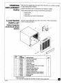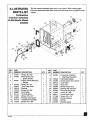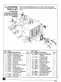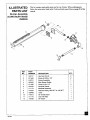
1
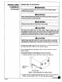
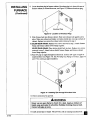
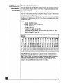
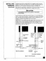
WINDOW WALL FURNACE
DIRECT VENT NATURAL GAS HEATER
OWNER'S OPERATION AND INSTALLATION MANUAL
25,000 and 40,000 Btu/Hr Furnaces
Model Numbers 2503532 and 4003532
WARNING:
If the information
in this manual is not followed exactly, a fire or
explosion may result causing property damage, personal injury, or oss of life.
Do not store or use gasoline or other flammable
vapors and liquids in the
vicinity of this or any other appliance.
WHAT TO DO IF YOU SMELL GAS
•
•
•
•
Do not try to light any appliance.
Do not touch any electrical switch; do not use any phone in your building.
Extinguish any open flame.
Immediately
call your gas supplier from a neighbor's phone. Follow the gas
supplier's
instructions.
• If you cannot reach your gas supplier, call the fire department.
Installation
and service must be performed
by a qualified installer, service
agency, or the gas supplier.
WARNING:
Improper
installation,
adjustment,
alteration,
service, or maintenance can cause injury or property damage. Refer to this manual for correct
installation and operational
procedures. For assistance or additional information
consult a qualified installer, service agency, or the gas supplier.
CONTENTS
SECTION
PAGE 1
S_etyInforma_on................................................................................................
3
Local Codes ..........................................................................................................
4
Unpacking....................................................................
5
Product_
...............................................................
5
.......................................................................................................
5
Installing Furnace .................................................................................................
6
Specifications
C-_k aas Xype.............................................................................................
6
Installation Items ............................................................................................
6
I.,ocating Furnace ............................................................................................
6
Creating
8
Wall Opening and Mounting Furnace .............................................
Installing Thermostat
Connecting
Checking
.....................................................................................
9
to Gas Supply ...........................................................................
13
Gas Connections
Connecting
..........................................................................
18
to Electrical Supply ..................................................................
Attaching Cabinet
Front Cover ....................................................................
19
19
OperatingFurnace...........................................
20
For Your Safety Read Before Lighting
........................................................
Operating Instructions ..................................................................................
To Tun_ OffGas to Furnace .........................................................................
21
22
Thermostat
22
Inspecting
Control Operation
Cleaning
Sequence ...............................................................................
and Maintenance
Troubleshooting
Wiring Diagrams
Service
.....................................................................
Burner Flame ....................................................................................
Normal Operating
.................................................................................
22
23
24
..................................................................................................
25
................................................................................................
28
Hints ......................................................................................................
Technical Service
...............................................................................................
Ordering Replacement
Parts ...............................................................................
Illuswated Parts List .......................................................................................
Warranty Information ..........................................................................
[]
20
28
28
29
29-36
Back Cover
SAFETY
INFORMATION
WARNINGS
IMPORTANT:
Read this owner's
manual carefully
and completely
before
trying to assemble, operate, or service this furnace. Improper use of this
furnace can cause serious injury or death from burns, fire, explosion,
electrical shock, and carbon monoxide poisoning.
DANGER
Carbon
monoxide
poisoning
Carbon Monoxide
Poisoning:
Early
resemble the flu, with headaches, dizziness,
the furnace may not be working properly.
may lead to death!
signs of carbon monoxide poisoning
and/or nausea. If you have these signs,
Get fresh air at once! Have furnace
serviced. Some people are more affected by carbon monoxide than others. These
include pregnant women, people with heart or lung disease or anemia, those under the
influence of alcohol, and those at high altitudes.
Natural Gas: Natural gas is odorless. An odor-making
The odor helps you detect a natural gas leak. However,
can fade. Natural gas may be present
agent is added to natural gas.
the odor added to natural gas
even though no odor exists.
Make certain you read and understand all Warnings. Keep this manual for reference.
It is your guide to safe and proper operation of this furnace.
1. A qualified
service person must install furnace.
2. Use only natural gas. Do not convert
furnace
to use different
fuel type.
3. If you smell gas
• Shut off gas supply.
• Do not try to light any appliance.
• Do not touch any electrical switch; do not use any phone
in your building.
• Immediately call your gas supplier from a neighbor's
phone. Follow the gas
supplier's instructions.
• If you cannot reach your gas supplier, call the fire department.
4. Do not block the flow of combustion
to the furnace.
air (outside
air)_or heated air (room air)
5. This furnace must have fresh air f°r pr°per °perati°n" If n°t' P°°r fuel c°mbusti°n
and improper venting of flue gases will result. Carbon monoxide poisoning from
backed-up flue gases could occur. The State of California lists carbon monoxide
as a reproductive toxin under Proposition 65.
6. Never install the furnace
• in a recreational vehicle
• on an inside wall
• in high traffic areas
• behind a door or where an open
door would block normal air flow
.
• in an alcove
• as a fireplace insert
• in windy or drafty areas
Provide the following minimum furnace clearances
from furnace
to combustibles
(as viewed from the front of furnace):
Below Front Cover: 6 inches
front cover
Adjoining Wall: 12 inches
Above Front Cover: 12 inches
Front: 8 feet
I!
201842
SAFETY
INFORMATION
Continued
LOCAL CODES
AWARNINGS
Continued
8. Provide the following minimum furnace clearances from furnace cabinet (portion of cabinet extending into outside air, as viewed from the rear of furnace):
Cabinet Back: 36 inches
Cabinet Sides: 6 inches
Cabinet Bottom: Must behigh enough off the groundto prevent snow, water,
leaves, or any other objects from blocking cabinet vents.
9. Always follow lighting instructions. Never attempt to light burnerwith a match
or butane torch.
10. Do not run furnace
• where flammable liquids or vapors are used or stored
• under dusty conditions
11. Never place clothing or any flammable objects on the furnace or venting system.
12. Furnace and venting system surfaces are very hot during operation. Keep
children and adults away from hot surfaces to avoid burns or clothing ignition.
Carefully supervise young children when they are in the same room as furnace.
Furnace will remain hot for a time after shutdown. Let surface cool before
touching.
13. Do not use furnace as a cooking device.
14. Do not alter furnace or its controls. Any change may create a safety hazard.
15. TtLrnOfffurnace and unplug and let cool before servicing. Unless you need gas
supply for testing, shut off manual shutoff valve before servicing. Only a
qualified service person should service and repair furnace and venting system.
16. Replace any safety screen or guard removed for servicing before running
furnace.
17. DO not use furnaceif any parthas been under water. Immediately call a qualified
service person to inspect the furnace and to replace any partof the control system
and any gas control which has been under water.
Install and use furnace
with care. Follow all local codes. In the absence
codes, use the latest edition
• National Fuel Gas
• National Electrical
• National Standard
*Available
from:
of local
of the following:
Code ANSI 7-..223.1, also known as NFPA 54 *
Code ANSI/NFPA 70 *
of Canada CAN/CGA-B149.2-M91
**
American National Standards Institute, Inc.
1430 Broadway
New York, N'Y"10018
National Fire Protection Association, Inc.
Batterymarch Park
Quincy, MA 02269
**Available
from:
Standards Council of Canada
350 Sparks Street
Ottawa. Ontario
KIR 7S8
This furnace must be grounded when installed. Follow all local codes. In the
absence of localcodes, refer to the National Electrical Code ANSI/NFPA No. 70
(U.S.A.)
or CSA C22.1 Canadian
Electrical Code, Part I (Canada).
!1
201_
LOCAL CODES
Continued
When installing furnace in a manufactured home (mobile home), follow the Manufactured Home Construction and Safety Standard, Title 24CFR, Part 3280 (formerly the Federal Standard for Mobile Home Construction and Safety, Title 24,
part 280; 1975). When such a standard is not applicable, follow the Standard for
Manufactured Home Installations, 1982 (Manufactured Home Sites, Communities
and Set-Ups),
ANSI A225.1/NFPA
501A.
In Canada, install furnace in accordance with Standard
Equipped Recreational Vehicles
codes and regulations.
UNPACKING
and Mobile Housing
I. Remove
furnace from carton.
2. Remove
all protective packaging
3. Remove
the following
CSA Z240.4
and any applicable local
applied to furnace
for shipment.
items from carton:
• Hardware package containing
mostat mounting plate
• Hardware package (thermostat
• Manual shutoff valve
If any of these items are missing,
furnace.
four large screws,
two small screws, and ther-
and two screws)
promptly
inform dealer where you bought
4. Check furnace for any shipping damage. If furnace
inform dealer where you bought furnace.
PRODUCT
FEATURES
Hot Surface Ignitor
This furnace has an electronic
batteries
- Gas
is damaged,
ignitor. There is no standing
promptly
pilot. No matches or
are required.
Thermostatic
The thermostat
Heat Control
is temperature
off. This results in the greatest
bills.
sensitive.
It automatically
heating comfort.
turns the furnace
on and
This can also result in lower gas
Limit Switch
The limit switch shuts off the gas to the main burner if the furnace becomes too hot
to operate safely.
SPECIFICATIONS
25,000
Model
Rated Heating Input (Btu/Hr)
25,000
Type Gas
Natural
Ignition
Hot Surface
Operating
Amps
Volts/Cycles
Main Burner
Pressure
Regulator
Setting
40,000
Model
Btu/Hr
40,000
Only
Natural
Ignitor
Only
Hot Surface Ignitor
1.5
2
120/60
1
120/60
2
3.5" W.C.
3.5" W.C.
Inlet Gas Pressure (in. of water)*
Maximum
7"
Minimum
5"
7"
5"
Dimensions, Inches (H x W x D)
Furnace
15 3/_2x 16 1/6x 23 5/8
15 V3_x 21 V4 x 23 V8
Weight
(pounds)
Furnace
53
71
Shipping
65
98
¢ For purposes of input adjustment.
_1_2
Btu/Hr
INSTALLING
FURNACE
Mounting hardware needed to mount furnace into wall is included with the famece.
No venting material is needed. You must famish tools and all gas piping from the
gas source to the furnace inlet.
AWARNING
A qualified service person must install furnace. Have service person
inspect furnace before use and at least annually. Follow all local codes.
NOTICE
This furnace must be electrically grounded. Follow all local codes.
In the absence of local codes, follow the National Electric Code,
ANSIINFPA
(Canada).
CHECK
70 (U.S.) or Canadian
Electrical
Code Part I-CSA C22.1
GAS TYPE
Use only natural gas. If your gas supply is not natural gas, do not install famace.
Call dealer where you bought furnace for proper type furnace.
INSTALLATION
ITEMS
Before instalfing furnace, make sure you have all items below.
• electric drill
• drill bits
• test gauge connection (see Figure 15,
page 17)
• piping (check local codes)
• Phillips screwdriver
• hammer
• pipe wrench
• stud locator or small finishing nails
• manual shutoff valve (supplied)
LOCATING
•
•
•
•
sealant (resistant to propane
ground joint union
sediment trap
tee joint
gas)
FURNACE
This furnace is designed to be mounted in a wall that is 4 to 18 inches thick. You
can also mount furnace in a window.
AWARNING
DO not install furnace
in Interior
wall of building.
You must install
furnace in exterior wall of building. Rear of furnace
into open, outside air. This lets poisonous exhaust
to the outdoors.
must extend
gases ventilate
WARNING
Turn off electrical
circuits that pass through
the wall where
you
ere going to Install the furnace.
WARNING
Malntaln the mlnlmum clearances shown In Flgure I, page 7. If
you can, provlde greater clearances from floor, celllng, and
m
Joining wall.
2O1842
INSTALLING
FURNACE
(Continued)
AWARNING
Never install the furnace
• in an inside wall
• in a recreation vehicle
• in a window recessed
• in an alcove
•
•
•
•
•
in a thick wall (creating
an alcove)
behind a door or where an open door would block normal air flow
as a fireplace insert
in high traffic areas
near furniture or draperies
in windy or drafty areas
If you install the furnace
I moving
vehicle
For convenience
will not
in a home garage,
ACAUTION
hit it,
and efficiency,
locate furnace
install furnace
• where there is easy access for operation, inspection,
• in a central location, near an electrical outlet
• where there is adequate
where
clearance
around
and service
vents outside
Before installing furnace, inspect the wall, floor, and outside areas. Make sure there
are no pipes, wiring, or anything else that would interfere with furnace installation.
If you are installing thermostat in wall, make sure there are no pipes or wiring in
the hollow wall above the furnace. The thermostat wires will pass through this wall
from the attic.
Minimum
Clearances
Provide the following minimum clearances from furnace front cover to combustibles (as viewed from the front of furnace, see Figure l):
Below Front Cover: 6 inches
Above Front Cover: 12 inches
Front: 8 feet
Adjoining Wall: 12 inches
Ceiling
T
12" Minimum
*--12"--_
_inimuml
Adjacent
Side
Well
6"Minimum
J
FinishedRoor,
Car_t,
Tile, etc.
Figure I - Mounting Clearances as Wewed from Front of Furnace
The clearance
between the cabinet and the wall it passes through
is 0 inches.
Provide the following minimum clearances from furnace cabinet (portion of cabinet
extending into outside air, as viewed from the rear of furnace) to obstructions:
Cabinet Back: 36 inches
Cabinet Sides: 6 inches
Cabinet Bottom: Must be high enough off the ground to prevent snow,
water, leaves, or any other objects from blocking vents.
201842
_l_
INSTALLING
FURNACE
(Continued)
CREATING
WALL
OPENING
Remove furnace front cover. Remove
cover. Lift front cover away.
Installing
AND MOUNTING
FURNACE
the two screws at the lower edges of front
in Normal Frame Wall
The 25,000 Btu/Hr model is designed to fit between two wall studs set at 16 inch
on center. The 40,000 Btu/Hr model will not fit between wall studs. Follow the
steps below to install.
1. Turn off electrical circuits that pass through mounting
no pipes or electrical wires in area you intend to cut.
wall. Make sure there are
2. Use stud locator or small finishing nail to find wall studs. When you locate
studs, drive a small finishing nail into each stud. This provides a visual reference for stud locations.
3. 25,000 Btu/Hr Model: Cut an opening in wall between the two studs. Make
opening 14 t/4" wide by 13 5Is" high (see Figure 2). iMPORTANT: You must
install furnace horizontally. Do not install furnace vertically.
40,000 Btu/Hr Model: Cut a 20 5h6" wide by 14 3Is" high opening
in wall (see
Figure 2). Start your cut right next to stud you are going to anchor cabinet to.
Cut across wall and through the next stud. Stop cut at proper width. IMPORTANT: You must install furnace horizontally. Do not install furnace vertically.
4. 25,000 Btu/Hr Model: Mark screw locations on wall (see Figure 2). Make sure
screws will anchor into studs. Make sure screw locations match screw holes on
cabinet flange.
40,000 Btu/Hr Model: Mark screw locations on wall (see Figure 2). Make sure
screws on one side will anchor into studs. Screws on other side will only anchor
in wall material. Make sure screw locations match screw holes on cabinet
flange.
5. 25,000 Btu/Hr Model: Use a proper-sized
into studs at marked locations.
40,000
Btu/Hr Model: Use a proper-sized
drill bit, Drill holes through
drill bit. On wal! stud side of opening,
drill holes through wail and into studs at marked locations.
holes through wall material.
On other side, drill
6. Insert furnace into opening. Do this from inside the room. Secure
wall with four large screws provided.
7. On outside of wall, caulk opening
wal! and
between
the cabinet
furnace
to
and the rough edges of
opening.
Wall Studs
Wall Studs
I
14 1/4"
Screw
Locations
20 5/16"
_
Wall
Opening
_
Screw
Well Opening
_"
!
25,000 Btu/Hr Model
=z
40,000 Btu/Hr Model
Figure 2 - Wall Openings and Screw Locations
201842
INSTALLING
FURNACE
(Continued)
Installing
in Masonry
Wall
You can mount both models in a masonry wall. Follow the steps below to install.
1. Cut opening in wall. Make opening 14 1/4" wide by 13 5Is" high for 25,000
Btu/Hr models. Make opening 20 5h6" wide by 14 3/8" high for 40,000 Btu/Hr
models. IMPORTANT'. You must install furnace horizontally.
Do not install
furnace vertically.
2. Secure furnace to wall with toggle bolts or hook bolts set in mortar.
3. Insert furnace into opening. Do this from inside the room. Secure furnace
with toggle bolts or hook bolts.
4. On outside of wall, caulk opening between the cabinet
opening. You can also use mortar to seal opening.
INSTALLING
to wall
and the rough edges of
THERMOSTAT
WARNING
Unplug furnace
before installing
thermostat.
Mount the thermostat directly on the furnace or on a wall in another part of the
room. If you have solid or masonry walls, mount the thermostat on the furnace.
Mounting
Thermostat
1. Unplug
furnace.
to Furnace
2. Locate red and white thermostat
wires are labeled "Thermostat."
3. Cut thermostat
4.
wires to desired
wires coming
out of side of furnace. These
length.
Route thermostat wires through slot/hole in side of thermostat mounting plate.
Then route wires through 5/8" diameter hole in center of plate (see Figure 4,
page 10).
5. Connect
thermostat
Figure 3). Connect
terminal.
White Wire
/_
wires to the two terminal
red wire to "R" terminal.
screws on back of thermostat
Connect
(see
white wire to "W"
ir
j.
Figure 3 - Connecting Thermostat Wires to Thermostat
Continued
201842
B
INSTALLING
FURNACE
l
6. Attach thermostat to thermostat mounting plate with screws provided (see
Figure 4). IMPORTANT." Note mounting plate position in Figure 4. Correctly
position mounting plate for your model furnace.
I
J
(Continued)
/
40,000 Btu/Hr Models
/
/
_
25,000 Bt_u_'lr Models
Figure 4 - Attaching Thermostat to Thermostat Mounting Plate
7. Insert thermostat mounting plate between wall and cabinet flange. Line up top
notch on mounting plate with top screw on flange (see Figure 5).
IMPORTANT" Thermostat for 25,000 Btu/Hr model mounts on right side of
furnace (see Figure 5). Thermostat
of furnace (see Figure 5).
40,000 Btu/Hr Models
for 40,000 Btu/Hr model mounts on left side
25,000 Btu/Hr Models
Figure 5 - Inserting Thermostat Mounting Plate
Between Wall and Cabinet Flange
8. Insert screw in cabinet flange and thermostat mounting
IMPORTANT."
plate and tighten firmly.
Make sure thermostat wires do not touch combustion
chamber.
I
2018_2
INSTALLING
FURNACE
(Continued)
Locating
Thermostat
on Wall
I. Locate thermostat 4 Ih to 5 feet above the floor on an inside wall away from
any heat sources. The thermostat needs to sense average room temperature.
Avoid the following:
COLD SPOTS
HOT SPOTS
Concealed
Fireplaces
pipes or ducts
Concealed pipes or ducts
Stairwells (drafts) or doors (drafts)
Unheated rooms on other side of wall
Registers
TV sets and radios
DEAD SPOTS
Behind doors
Lamps or direct sunlight
Kitchen
2. Before
installing
Comers
thermostat,
inspect
and alcoves
the wall, floor, and attic areas. Make sure
there are no pipes, wiring, or anything else that would interfere with installing
thermostat. Do not mount thermostat to stud. If there are any obstructions, choose
a new location.
3. Provide two 18-gauge insulated stranded wires for the thermostat
wire. Also
provide two wire nuts, and two wall anchors. There is a red and a white thermostat
wire coming from the furnace. The extra thermostat wires you furnish attach to
these wires. Make sure you furnish a red and a white wire. This will insure correct
hookup. Purchase enough thermostat wire to go from the furnace to the thermostat
location. Do not cut and splice this wire. The thermostat wire must be unbroken.
Routino Thermostat
Cable
All wiring must meet local codes. The following instructions cover routing the wire
through the attic. You can run wiring from a basement or crawl space.
1. Unplug
2.
furnace.
Before drilling hole in wall, drive a small finishing nail through ceiling directly
above thermostat location. Pull nail out and push a small stiff wire through hole.
This helps you locate thermostat mounting location when in attic.
3. In attic, locate stiff wire. Drill liT' hole in center of ceiling wall plate next to stiff
wire. Remove wire.
4.
Probe through drilled hole in wall plate with a stiff wire to make sure there are no
pipes, wiring, or anything else blocking the way for thermostat wires, If you find
blockage, choose new location for thermostat.
5. Drill a liT' hole through
6.
the wall at thermostat
From attic, feed thermostat
thermostat location.
wires through
mounting
hole in ceiling
location.
plate until wires reach
7. Make a small hook with a piece of stiff wire. Run wire hook through liT' hole in
wall. Hook thermostat wires. Pull wires through hole in wall. Make sure 6" of wires
stick out.
8. Drive a small finishing nail in ceiling above furnace.
25,000 Btu/Hr Model - Drive nail above right side of furnace.
40,000 Btu/Hr Model - Drive nail above left side of furnace.
Pull nail out and push a small stiff wire through
wire routing location when in attic.
9. Repeat
hole. This helps you locate
steps 3 and 4 above.
10. Feed thermostat wires from attic to furnace through 1/2" hole in ceiling wall plate.
11 .Connect thermostat wires from attic to thermostat wires on furnace. Connect red
wires together, then connect white wires together. Use wire nuts to make connections. IMPORTANT:
Make sure thermostat
wires do not touch combustion
chamber.
201842
Continued
_
INSTALLING
FURNACE
(Continued)
Mountina the Thermostat to Wall
1. Connect thermostat wLmsto the two terminal screws on back of thermostat (see
Figure 6). Connect
nal.
red wire to "R" terminal. Connect
white wire to "W" termi-
2. Push any excess wire back through hole in wall and plug hole with insulation
prevent drafts. Drafts affect the thermostat operation.
3. Use thermostat
base to mark mounting
screw locations.
4. Drill proper-sized
holes for wall anchors.
5. Attach thermostat
to wall using screws provided
White Wire
to
(see Figure 7).
\
Figure 6 - Connecting Thermostat Wires to Thermostat
Figure 7- Mounting Thermostat to Wall
[]
201842
INSTALLING
FURNACE
(Continued)
CONNECTING TO GAS SUPPLY
l
A qualified service person must connect
AWARNING
Follow all local codes.
furnace
to gas supply.
AWARNING
Never connect furnace to private (non-utility)
commonly known as well-head gas.
Unplug
furnace
before
gas wells.
This gas is
connecting
to gas supply.
WARNING
t
CAUTION
Use only
acceptable
new, black iron or steel pipe. Copper tubing
may be
in certain areas. Check local codes. Use pipe large enough
in diameter to allow proper gas volume to furnace. If pipe is too small,
undue loss of pressure will occur. Refer to chart on page 16.
CAUTION
Lightly apply pipe joint sealant to male threads before connecting.
Use pipe joint sealant that is resistant to liquid petroleum (LP) gas.
All piping must comply with local codes and ordinances or with the National
Gas Code (ANSI Z223.1 NFPA No. 54), whichever applies.
Yon can connect furnace
furnace (outside).
Connecting
Furnace
to gas supply at front of furnace
to Gas Supply
(inside)
Fuel
or at rear of
at Front of Furnace
1. Locate gas inlet pipe on lower, right front of furnace
(see Figure 8).
3/8" Pipe
Nipple
Gas Inlet Pipe
Figure 8 - Connecting Gas from Inside of Room
2. Connect 3/8" pipe or nipple to gas inlet pipe (see Figure 8). See Providing Gas
Piping to Furnace, pages 16 and 17 for correct gas pipe installation.
Continued
[]
201842
INSTALLING
FURNACE
Connecting
Fumace
to Gas Supply
at Rear of Furnace
1. Remove the two screws in back of furnace cabinet located by the exhaust
vent(s) (see Figures 9 and 10).
(Continued)
Figure 9 - Locations of Screws in
Back of Furnace Cabinet
(25,000 Btu/Hr Model)
2.
Figure 10 - Locations of Screws in
Back of Furnace Cabinet
(40,000 Btu/Hr Model)
Remove two screws on front lower flange that attach furnace flange to furnace
cabinet flange (see Figure 11). Note: 40,000 Btu/Hr model has a bottom shield
(see parts list, page 31, for location).
shield.
Removing
two screws will detach bottom
Furnace
=a
Cabinet Flange-
Flange
Figure 11 - Removing Screws on Lower Flange (40,000 Btu/Hr Model Shown)
3. Slide furnace out of furnace
cabinet.
4. Locate gas inlet pipe on lower, right front of furnace.
5. 40,000 Stu/Hr Model Only: Remove screw holding
furnace.
6.
Disconnect gas inlet pipe from 3/8" manifold
clockwise to disconnect (see Figure 12).
gas inlet pipe clamp to
elbow. Turn gas inlet pipe counter
Remove Screw, __"
40,000 Btu/I-Ir
Model Only
Gas Inlet
Pipe
Aanifold Elbow
Rgure 12 - Disconnecting
m
7. Rotate the 318" manifold
Figure 12).
Gas Inlet Pipe (40,000 Btu/Hr Model Shown)
elbow 90 ° so the opening is pointing
downward
(see
INSTALLING
FURNACE
8. Locate knockout plug in furnace cabinet. Knockout plug is in lower left rear of
furnace cabinet (as viewed from rear, see Figure 13). Remove knockout plug.
(Continued)
J
Knockout Plug
J
Figure 13 - Location of Knockout Plug
9. Slide furnace
back into furnace
place. Make sure exhaust
cabinet.
10.25,000
Replace
tube gaskets are in
and intake vent tubes extend into vent caps on back of
two screws by exhaust
Btu/Hr Model:
flange and furnace
cabinet. Make sure exhaust
Replace
vent(s) removed
two screws removed
in step 1.
in step 2. Attach furnace
cabinet lower flange together.
40,000 BttdHr Model: Place bottom shield back in place. Replace two screws
removed in step 2. Attach bottom shield, furnace
lower flange together.
flange, and furnace
cabinet
11.Run 3/8" pipe or nipple through knockout hole. Connect 3/8" pipe or nipple to
manifold elbow (see Figure 14). See Providing Gas Piping to Furnace, pages 16
and 17 for correct gas pipe installation.
Figure 14 - Inserting Pipe through Knockout Hole
12. Cheek connections for gas leak.
AWARNING
Never use an open flame to check for a leak. Apply a mixture of
liquid soap and water to all joints. Bubbles forming show a leak.
Correct all leeks at once.
13. Caulk around pipe or nipple. This prevents cold air entering
201842
knockout
hole.
INSTALLING
FURNACE
(Continued)
Providing
Gas Piping to Fumace
You must provide gas piping from gas source to furnace. The gas piping must be in
a vertical position where it connects to the furnace. This prevents interference with
front cover installation.
Consult your local gas company for proper routing of the gas lines.
Pipe size is determined by the length of pipe from the gas source to the fumaee and
the total Btu load on the gas source.
Add the total Btus required for all appliances connected
to the gas source including
this furnace. Divide this number by 1030. This will give you the approximate cubic
feet per hour needed.
Example:
40,000
+ _
55,000
Btu/Hr for furnace
Btu/Hr for other gas appliances
Btu/Hr total
55,000 + 1030 = 53.4
Locate 53.4 or higher on chart below.
According to the chart below, you should use 50 feet or less of liT' pipe,
200 feet or less of 3/4" pipe, etc...
MINIMUM
IRON PIPE
SIZE
10
3/8"
72
I/2"
132
3/4"
278
1"
1 V4"
1 _h"
2"
2 lh"
3"
4"
520
1050
1600
3050
4800
20
49
92
190
350
730
1100
2100
3300
30
40
73
152
40
34
63
130
50i
30
56
115
LENGTH OF
60
70
27
25
50
46
105
96
PIPE (FEET)
80
gO 100
23
221 21
43
401 38
90
84
79
125
18
34
72
150
17
31
64
175
15
28
59
200
14
26
55
285 245 215 195 180 170 160 150 130 120 110
590 500 440 400 370 350 320i 305 275 250 225
890 760 670 610 560 530 490 460 410 380 350
1650 1450 1270 1150 1050 990 930 870 780 710 650
2700 2300 2000 1850 1700 160011500 1400 1250 1130 1050
100
210
320
610
980
8500 5900 4700 4100 !3600 3250 3000 2800 2600 2500 2200 2000 1850 1700
17500 12000 9700 8300 ?400 6800 6200 5800 5400 5100 4500 4100 3800 3500
IMPORTANT: Check gas line pressure at gas meter before connecting furnace to
gas line. Gas line pressure must be no less than 5 inches of water and no greater
than 7 inches of water. Gas pressures and input to the burners must not exceed the
rated input and pressure shown on the rating plate. For natural gas, manifold
pressure should be 3.5 inches of water. For elevations above 2000 feet, reduce
rating 4% for each 1000 feet above sea level (U.S.A. only).
m
201842
INSTALLING
FURNACE
(Continued)
Installation must include a manual shutoff valve (supplied), ground joint union,
plugged I/8" NPT tap, and a sediment trap. Locate NPT tap within reach for test
gauge hook up. NPT tap must be upstream from furnace (see Figure 15).
Apply pipe joint sealant lightly to male threads. Prevent excess sealant from going
into pipe. Excess sealant in pipe could result in clogged furnace valves.
CAUTION
Use pipe joint sealant
leum (LP) gas.
that is resistant
to liquid petro-
Install sediment trap in supply line as shown in Figure 15. Locate sediment trap
where it is within reach for cleaning. A sediment trap traps moisture and contaminants. This keeps them from going into furnace controls. If sediment trap is not
installed
or is installed
IMPORTANT."
wrong, furnace
Locate sediment
may not run properly.
trap where trapped
matter
will not freeze. Install
sediment trap in a vertical run of pipe. If gas piping enters furnace from rear
(outside), you must locate sediment trap in crawl space (see Figure 15). If you
install furnace in structure with slab foundation, you must install gas piping to
front of furnace (inside) (see Figure 15).
3" Min.
Manual Shutoff
Valve
Gas Piping
Entering
Furnace
Front
Gas Piping
Entering
Furnace
Rear
Test Gauge
(Inside)
(Inside)
To Gas Supply
,, \ _.
Shutoff
Valve
Manual
Trap
To Gas
Slab Floor Installation
Test Gauge
Connection
Sediment
Trap
Crawl Space Installation
Figure 15 - Gas Connection
m
201842
INSTALLING
CHECKING
FURNACE
(Continued)
1
GAS CONNEC_ONS
AWARNING
Test all gas piping and connections
servicing. Correct aU leaks at once.
for leaks after Installation
or
,WARNING
Never use an open flame to check for a leak. Apply a mixture
liquid soap and water to all joints.
Correct all leaks at once.
Pressure
Testing
Bubbles
forming
of
show a leak.
Gas Supply Piping System
Test Pressures In Excess Of 1/2 PSIG
1. Disconnect furnace and its individual manual shutoff valve from gas supply
piping system.
2. Cap off open end of gas pipe where manual shutoff valve was connected.
3. Pressurize supply piping system by either using compressed air or
opening main gas valve located on or near gas meter.
4. Check all joints of gas supply piping system. Apply mixture of liquid soap and
water to gas joints. Bubbles forming show a leak.
5. Correct all leaks at once.
Test Pressures Equal To or Less Than 1/2 PSIG
1. Close manual shutoff valve (see Figure 16).
2. Pressurize supply piping system by either using compressed
gas valve located on or near gas meter.
air or opening
3. Check all joints from gas meter to manual shutoff valve. Apply mixture
soap and water to gas joints. Bubbles forming show a leak.
4. Correct all leaks at once.
Pressure
1.
2.
3.
4.
Open
Open
Make
Check
Testing
Furnace
of liquid
Gas Connections
manual shutuff valve (see Figure 16).
main gas valve located on or near gas meter.
sure control knob of furnace is in the OFF position.
all joints from manual shutoff valve to gas inlet pipe. Apply
liquid soap and water to gas joints.
5. Correct all leaks at once.
6, Turn on furnace (see Operating
main
Bubbles forming
Furnace,
joints for leaks.
7. Turn off furnace (see To Turn OffGas
mixture of
show a leak.
page 20). Check the rest of the internal
to Furnace,
page 22).
On Position
Off Position
!
Figure 16 - Manual Shutoff Valve
20f8A2
INSTALLING
FURNACE
(Continued)
CONNECTING
TO ELECTRICAL
SUPPLY
IMPORTANT." Follow all local codes when connecting electricity to furnace. In
the absence of local codes, refer to the latest edition of the National Electrical Code
ANSI/NFPA No. 70. If you are not familiar with wiring codes, have a qualified
electrician do the wiring.
It is best to plug furnace
1. Supply
into a separate
a 120-volt, 60-cycle,
grounded
2. The furnace has a three-pronged
prong outlet.
and permanent
electrical
outlet at furnace
(grounded)
line circuit.
location.
plug. Use only a grounded,
three-
IMPORTANT."
Some local codes require rigid or semi-rigid conduit or metallic
sheathe cable. When using a metallic sheathe cable, the installer must terminate the
supply wire in the terminal
Performance
box opening.
Check
Plug furnace into three-pronged
ignition or if the valve chatters,
1. Unplug
outlet. If ignitor remains on after main burner
you may have reversed polarity.
furnace.
2. Turn off electricity to outlet.
3. Reverse 120-volt connections
4, Turn on electricity
inside outlet.
to outlet.
5. Plug in furnace. Ignitor should turn off after main burner ignites. If ignitor does
not turn off, or if valve continues to chatter, turn off furnace and unplug. Call a
qualified service person.
A'n'ACHING
CABINET
FRONT
COVER
ACAUTION
Do not operate furnace with front cover removed or mounted
wrong. If front cover is mounted wrong, you cannot secure it to
cabinet with screws.
1. Hook top of front cover over top cabinet
flange.
2. Secure the sides of front cover to lower sides of furnace
provided
(see Figure
IMPORTANT:
cabinet
with two screws
17).
You may have removed
furnace
from furnace
cabinet
during
installation. You must correctly install furnace within cabinet. If not, front cover
will not properly attach to cabinet. Make sure gaskets for intake and exhaust tubes
are in place. Make sure intake and exhaust tubes extend into vent caps on cabinet
back and are secured with screws. Make sure you secured flange on bottom of
furnace to flange on bottom front of cabinet.
Figure
201842
17 - Attaching
Front
Cover
to Cabinet
[]
OPERATING
FURNACE
AWARNING
Furnace
burner, combustion
chamber,
and exhaust
port are very
hot during operation. Keep children and adults away from hot
surfaces to avoid burns and clothing ignition. Carefully supervise
young children when they are in the same room as furnace. Furnace
will remain hot for a time after shutdown. Let surface cool before
touching.
AWARNING
Do not operate
could result.
furnace
with front cover removed.
Unsafe
operation
CAUTION
Do not block circulating
air openings
cover. This is necessary
for furnace
in the louver of the front
to operate
properly.
NOTICE
If operating
furnace
for the first time, a slight odor will occur. This
odor will go away after a few hours of operation.
FOR
YOUR
SAFETY
READ
BEFORE
LIGHTING
WARNING
If you do not follow these instructions
may result causing property damage,
A.
This appliance
does not have a pilot. It is equipped
which automatically
B.
exactly,
personal
a fire or explosion
injury, or loss of life.
with an ignition device
lights the burner. Do not try to light the burner by hand.
BEFORE OPERATING smell all around the appliance area for gas. Be sure to
smell next to the floor because some gas is heavier than air and will settle on
the floor.
WHAT
TO DO IF YOU SMELL GAS
• Do not try to light any appliance.
• Do not touch any electric switch; do not use any phone
• Immediately call your gas supplier
gas supplier's instructions.
from a neighbor's
• If you cannot reach your gas supplier,
in your building.
phone. Follow the
call the fire department.
C.
Use only your hand to mm the handle on the manual shutoff valve. Never use
tools. If the handle will not turn by hand, don't try to repair it. Call a qualified
service technician. Force or attempted repair may result in a fire or explosion.
D.
Do not use this appliance if any part has been under water. Immediately call a
qualified service technician to inspect the appliance and to replace any part of
the control system and any gas control which has been under water.
m
201842
OPERATING
OPERATING
INSTRUCTIONS
FURNACE
(Continued)
Always follow lighting Instructions.
with a match or butane torch.
Never attempt
AWARNING
1.
STOP! Read the safety information on page 20.
2.
Set the thermostat
3.
Turn off all electric power to the furnace.
4.
Turn manual shutoff valve clockwise
to light burner
t
to lowest setting.
to OFF position (see Figure 18).
_
On Position
Off Position
Figure 18 - Manual Shutoff Valve
5.
Wait five (5) minutes to clear out any gas. Then smell for gas, including near
the floor. If you smell gas, STOP! Follow "B" in the safety information
on page
20. If you don't smell gas, go to next step.
6.
Turn manual shutoff valve counterclockwise
18).
_
to ON position (see Figure
7.
This furnace is equipped with an ignition device which automatically
lights the
burner. Do not try to light the burner by hand.
8.
Plug in furnace.
9.
Set thermostat to desired setting. If thermostat
the blower will come on.
is set above room temperature,
10. Allow approximately 45 seconds for ignition to occur. When ignition occurs,
the glo-bar will stay on for a short period of time. The flame sensing probe will
sense the burner flame and shut off glo-bar.
If ignition does not occur within 22 seconds,
the ignition control will attempt to
light burner three times. This will take about two minutes. If ignition does not
occur, the ignition control will lock out the glo-bar and valve circuit. Air in the
gas line or a short gas interruption will prevent furnace from igniting. If this
happens, turn thermostat off and wait 5 minutes. Turn the thermostat
The furnace will try to ignite again.
11. If the furnace still does not ignite, follow
Furnace,
furnace.
page 22. Call as qualified
instructions
service person.
back on.
To Turn OffGas
Do not attempt
to
to restart
Co_n_d
I
201842
OPERATING
FURNACE
(Continued)
_
TO TURN OFF GAS TO FURNACE
1.
Set thermostat
to lowest setting
2.
Turn manual gas valve clockwise
_
to OFF position.
Do not force
manual gas valve.
3.
Unplug
furnace if service is to be performed.
To Shut Down
1.
Furnace
for an Extended
Tum manual gas valve clockwise _
Period of Time
to OFF position. Do not force
manual gas valve.
2.
Set thermostat
on OFF.
CAUTION
Do not try to adjust
valve.
heating
levels by using the manual
THERMOSTAT
The thermostat responds
CONTROL
to the room temperature.
shutoff
OPERATION
When the room temperature
drops below the thermostat setting, the thermostat turns the furnace burner and
blower on. When the room temperature goes above the thermostat setting, the
thermostat turns the furnace burner off. The blower will continue to blow about two
to three minutes after the burner goes out. The thermostat
constant
INSPECTING
BURNER
FLAME
keeps the room at a
temperature.
To observe
burner flame, remove
furnace
front cover. Remove
the two screws at
the lower edges of front cover. Lift front cover away. Locate viewing window
front of combustion chamber. You can see burner flame through this window.
Correct
Incorrect
Burner Flame: Blue flame with well-defined
burner ports.
Burner Flame: Yellow or lazy flame without well-defined
If burner flame is incorrect, shut off furnace
0
0
Correct Rame Pattern
and contact
on
a qualified
0
burner ports.
service person.
0
Incorrect Flame Pattern
Figure 19. Burner Flame Patterns
m
201842
NORMAL
OPERATING
SEQUENCE
1.
When the room temperature drops below the thermostat setting, the thermostat
calls for heat. A 24-volt circuit is completed through the time delay relay coil.
After three to five seconds, the contacts in the relay close. The blowers come on.
2.
One motor drives both the combustion
air blower and the circulating
room air
blower. The combustion air blower draws air from outside through the intake
air vent. This air discharges into the combustion chamber. The combustion air
blower then forces the combustion
products out of the exhaust tube(s). The
Combustion air blower is sealed so that air does not pass between
circulating room air blower.
3.
it and the
When the blower motor reaches 75% of normal r.p.m. (three to five seconds),
air from the blower turns on the microswitch. When the microswiteh activates,
the electrical circuit is completed
through
the limit switch to the control
module. The glo bar begins to glow. In about 15 seconds,
the glo bar becomes
hot enough to ignite the burner.
4.
Another 24-volt circuit is completed
through
the module
to the main gas valve.
The valve opens. Gas passes through the valve to the main burner. The gas is
ignited by the glo bar.
5.
After the main burner ignites, the flame detector senses the presence of flame.
This opens the circuit to the glo bar. The glo bar shuts down.
6.
The circulating room air blower pulls return air in from the living area. This air
is heated as it flows past the combustion
out into the room.
7.
When the room temperature
chamber. The heated air is then blown
rises above the thermostat
setting, the circuit to
the valve opens and the burner shuts off.
8.
The blower continues
to run about two to three minutes
relay coil cools. When the coil cools, the circuit
blower shuts off.
until the time delay
to the motor opens. The
Limit Switch
I
Oo not operate
furnace
"'°°
without
a properly-working
I
limit switch.
The limit switch will turn off the gas to the main burner if the furnace
hot. when this happens, the main burner will go out and the blower
run for two to three minutes. This usually happens when circulating
or completely blocked.
becomes
too
will continue to
air is partially
Occasional cycling of the limit switch is not bad. This indicates safe operation.
Limit switch cycling will most likely occur on warm days. If this happens too often
or for a long period of time, the circulating air system should be thoroughly cleaned
by a qualified service person.
If the circulating air system is cleaned and the limit switch continues to shut down
the furnace, the limit switch is defective. A defective limit switch cannot be repaired. It must be replaced.
limit switch.
For safety reasons,
never operate
the furnace
without a
II
201842
CLEANING
AND
MAINTENANCE
AWARNING
Turn off and unplug furnace and let cool before cleaning.
Turn
manual shutoff valve to OFF position. Only a qualified service
person should service and repair furnace.
AWARNING
Keep furnace clear and free from combustible
and other flammable vapors and liquids.
materials,
gasoline,
A CAUTION
You must keep control areas, burner, and circulating air passageways of furnace clean. Inspect these areas of furnace before each
use. Have furnace inspected yearly by a qualified service person.
Furnace may need more frequent
from carpeting, bedding material,
cleaning
etc.
due to excessive
lint
CABINET
Air Passageways
• Use a vacuum cleaner or pressurized
air to clean.
Exterior
• Use a soft cloth dampened
and front cover to remove
• Use a vacuum cleaner
EXHAUST
AND
with a mild soap and water mixture.
dust.
to remove
INTAKE
Wipe cabinet
dust from front cover louvers.
VENTS
Make sure the exhaust and intake vents are not blocked.
The intake combustion
and the exhaust gases must be expelled to the outside. Have a qualified
person clean dirt and loose debris from vents annually.
air
service
GASKETS
Inspect all gaskets_ If any gaskets show signs of leakage or damage,
Safe operation of furnace depends on all gaskets being tight.
FRONT
replace
them.
COVER
Remove anything that may be blocking the air to the louvers of the front cover.
COMBUSTION
CHAMBER
AND MAIN BURNER
Check flame pattern of main burner often (see Inspecting Burner Flame, page 22).
Have combustion chamber and main burner cleaned if you have run the furnace
with a high yellow flame. Incomplete combustion from lack of air causes the
yellow flame. This deposits soot inside the combustion chamber and on the burner.
Contact a qualified service person to clean combustion chamber and main burner.
OUTSIDE
VENT
CAPS
Inspect outside vent caps for obstructions or soot. If soot is found, do not use
furnace. Contact a qualified service person to clean furnace.
I
m
201842
TROUBLESHOOTING
AWARNING
Turn off and unplug furnace and let cool before servicing. Unless
you need gas supply for testing, shut off manual shutoff valve
before servicing. Only a qualified service person should service
and repair furnace.
COMPLAINT--NO
1. Thermostat
HEAT
Off
Check to be sure thermostat
terminal.
is calling for heat. Wire to thermostat
could be off
2. Gas Supply
Be sure manual gas valve is in the open position (level or parallel to gas line).
3. Electrical
Connections
Be sure all electrical
and Power
connections
are secure.
4. Motor
Motor must be operating at top speed before burner will come on. If blower is not
operating at top speed, check voltage supply (minimum 100 volts A.C.). If voltage
supply is okay, check for defective motor.
5. Malfunctioning
Microswitch
Be sure the microswitch
is sailing in far enough to open the solenoid
valve and to
energize the ignition control. If the switch is not sailing in, clean any dust or dirt from
the actuator pin. Other reasons for the switch not sailing in are:
A. Insufficient blower speed - Slow motor due to faulty motor or lint and dust
accumulation on the blower wheels or restriction of return air to the furnace.
B. Faulty microswitch
- Replace switch ifcircuit to ignition control is not completed
when switch is manually engaged. Switch should also be replaced if blower
motor running at top speed fails to engage switch within six or seven seconds.
Note: To service switch, combustion chamber must be pulled out. Follow steps
1, 2, 3, 9 and 10on pages 14 and 15 to remove combustion chamber.
6. Gas Valve
Within 20 seconds after motor reaches 75% of its r.p.m, and microswitch
check the following:
A. Voltage at valve - If current
connections.
B. If wire connections
is present
but valve is not opening,
engages,
check
wire
okay - Replace valve.
C. No voltage at valve - Check circuit completion through microswitch and limil
switch as well as wiring and wire connections. If no defects are found, see ste
9 under Igm'tion Failures, page 26.
7. Blower
Not Operating
A. Check power supply to furnace.
B. Check electrical
connections
at furnace.
C. With thermostat points closed, check for circuit completion at motor. If voltag_
is present, replace motor. If no voltage is present at motor, check for:
• 24 volts on secondary coil or transformer.
If no voltage, replace transformer
• If 24 volt transformer okay, check for circuit completion across contacts or
time delay relay. Allow three to five seconds for contact to close.
Continued
201842
[]
TROUBLE-
SHOOTING
(Continued)
• If circuit across contacts okay, check continuity of wiring in motor circuit
8. Short Cycling
(motor goes on and off)
A. Check thermostat. Contacts should remain closed. If contacts are breaking:
• Check thermostat
• If anticipator
anticipator
setting. It should be between
.75 and 1.0.
setting okay, check amp draw across thermostat.
If amp draw
exceeds .65, check amp draw across coil of valve and time delay relay. Note:
On initial operation ofglo bar, there is a momentary surge of approximately 4.0
amps.
• If amp draw is within limits, check for shorts in thermostat
wiring.
• If wiring is okay, replace thermostat.
9. Ignition
Failures
WARNINGS:
• Never connect
unit or ignition
circuit to 230 volts.
• Never operate unit with glo bar touching
Damage to ignition control will occur.
burner or any other ground.
• Besure sensor probe never touches glo bar.This
control.
• If the ignition control
repairable.
is defective,
will damageignition
it must be replaced,
CAUTION: Do not attempt to repair the ignition
it and cause it to operate incorrectly.
it is not field-
control. This may alter
The electronic system is made up of two parts: the ignition control and the glo bar.
The ignition control is the brain of the electronic system. It has several functions:
1. When the blower reaches full r.p.m., a 24-volt circuit is completed
to the ignition
control. (Check across yellow and orange wires.)
2. The red and blue wires at the ignition control are the 120-volt input for the globar circuit. When the 24-volt circuit is completed, the ignition control will
complete the 120-volt circuit to the glo bar and it begins to glow. (Check this
circuit across the two white wires at the ignition control.)
3. After approximately 20 seconds, a 24-volt circuit is completed through the igmtion
control to the gas valve, (This circuit is checked from brown wire at ignition control
to a neutral ground.) This circuit opens the valve, gas flows to the burner and is
ignited by the heat from the glo bar. Note: Glo bar remains on.
4. When the burner flame is established, the sensing probe will sense the presence
of burner flame and open the glo-bar circuit. The glo bar will then stop glowing.
It is important to determine
the type of problem
being experienced.
checkout procedure can be made. The following is a list of problems,
in which area the problem is located, and how to correct it.
1. GIo bar will not glow - With blower running and mieroswitch
following:
Then the proper
how to identify
engaged, check the
A. Check for 24 volts A.C. across yellow and orange wires at ignition control.
If no voltage, check microswitch and limit switch for circuit completion as
well as wiring and wiring connections.
B. Voltage present across yellow and orange wires, check for 120-volt input to
ignition control across red and blue wires. If no voltage, check wiring all the
way back to power supply.
C. 120 volts present across red and blue wires, check for 120 volts across the tw(
white wires at ignition control. If no voltage, replace ignition control.
20184
TROUBLESHOOTING
(Continued)
D. Voltage present across the two white wires, check wiring and wire connections to glo bar.
E. If wiring and wire connections
2.
okay, replace glo bar. (Glo bar broken).
Glo bar glows but burner will not come on.
A. Check for voltage (24 volts A.C.) at valve 40 seconds after glo bar begins to
glow. If voltage present but valve not opening, replace valve.
B. If no voltage at valve, check brown wire at ignition control for continuity
good connection.
C. If wire and wire connections
3.
Glo bar operating
and
okay, replace ignition control.
and gas valve opening
but burner will not light.
A. Check gas flow through burner. If no gas is coming through burner, check for
obstruction in gas line, main burner orifice, or main burner.
B. If thermostat
okay, check for 24 volt A.C. circuit completion
across yellow
and orange wires at ignition control. If no voltage, check for circuit completion through limit switch and microswitch.
C. If voltage is present at ignition control across yellow and orange wires yet
burner continues to go off, replace ignition control.
4.
If the ignitor remains on after main burner ignition or the valve chatters, reverse
the 120-volt A.C. connections
at the wall receptacle.
A. If polarity is okay yet burner continues to go off, check thermostat to be sure
it is still completing the valve circuit. If not, check for excessive amp draw
in valve circuit.
B. If thermostat
okay, check for 24 volt A.C. circuit completion
across yellow
and orange wires at ignition control. If no voltage, check for circuit completion through limit switch and microswitch.
C. Voltage present at ignition control across yellow and orange wires yet bumer
continues to go off, replace ignition control.
5.
Burner cycles off and glo bar comes on immediately,
check the following:
A. Check flame sensing probe. Be sure probe is positioned in the burner flame
and glowing cherry red. Check wire and wire connections at probe and
ignition control.
B. Ifwire and wire connections okay, check for voltage across brown and orange
wires at ignition control. If no voltage, replace ignition control.
C. If voltage present, check wiring and wire connections
D. If wire and wire connections
COMPLAINT_XCESSIVE
1. Blower
Replace
2. Motor
Replace
at valve.
okay, replace valve.
NOISE
Out of Balance
blower.
Hums
motor.
COMPLAINT--MAIN
BURNER
WILL
NOT
CYCLE
OFF
1. Check thermostat.
2. Gas Valve Stuck Open
Check gas valve. If stuck open, replace. Do not attempt
COMPLAINTDFURNACE
Check
201842
WILL
NOT
all wiring to assure proper connection
to repair valve!
OPERATE
or detect possible shorts.
_1_
WIRING
DIAGRAMS
SJl S_ch
Juncdon
Probe
Whilo
NOTE: If _u must replace any wire, replace
w#h type 105°C or equivalent.
• White wire in cord set or "dbbed"wire in cord set,
# TGS 150" C Iotack
Figure 20 - Wiring Diagram (25,000 Btu/Hr ModeO
WNte
Probe
NOTE: If you must replace any wire, replace
with type 105°C or equivalent.
• Whif.ewire in cond set or "ribbed"wire in cord set`
$ TGS 150_ C blad_
Figure 21 - Wiring Diagram (40,000 Btu/Hr Model)
SERVICE
HINTS
When gas pressure is too low
• glo-bar glows, but burner will not ignite
When gas quality is bad
• burner will not stay lit
• burner will produce flames and soot
You may feel your gas pressure is too low or gas quality is bad. If so, contact your
local gas supplier.
TECHNICAL
SERVICE
_m
You may have further questions about installation, operation, or troubleshooting.
If so, contact your installer, a qualified service person or Williams Technical Help
Line at 1-800-266-0993.
2O1842
ORDERING
REPLACEMENT
PARTS
Note: Use only original replacement
for parts replaced under warranty.
All parts listed herein may be ordered
parts. This will protect your warranty covera I
from your equipment
When ordering repair parts, always give the following
supplier.
information:
• Model number
• Type of gas
• Replacement
ILLUSTRATED
PARTS LIST
part number and description
This list contains replaceable pa_s used in your furnace.
follow the instructions above.
When ordering
parts,
Cabinet Assembly
25,000 Btu/Hr Model
2503532
KEY
NO.
1
2
3
4
5
6
7
8
A
A
A
A
A
PART
NUMBER
DESCRIPTION
030643
121520
191240
160912
100892
070509
121224
062242
070542
070508
191244
191246
531010
191293
Front Cover Assembly
Screw, #8 x 3/8"
Front Cover Trim*
Thermostat
Cabinet Assembly
Cabinet Insulation (right and left sides)
Screw, #10 x 3/4"
Thermostat Mounting Plate
Cabinet Insulation (back)
Cabinet Insulation (top)
Operating Instructions Decal (English)
Operating Instructions Decal (French)
Warning Decal
Nameplate
QTY.
1
2
1
1
1
1
4
1
1
1
1
1
1
1
Parts not shown.
• You must order nameplate and operating instructions decal separately.
201842
_,,
ILLUSTRATED
PARTS LIST
This list contains replaceable parts used in your furnace. When ordering parts,
follow the instructions listed under Ordering Replacement Parts on page 29 of this
manual.
Cabinet Assembly
40,000 Btu/Hr Model
4003532
7
KEY
NO.
1
2
3
4
5
6
7
8
9
10
A
A
PART
NUMBER
280498
121520
191241
030642
100896
070511
120158
160912
121224
O62242
070541
070510
191245
191247
531010
191293
DESCRIPTION
QTY.
Bottom Shield
Screw, #8 x 3/8"
Front Cover Tdm*
1
2
1
Front Cover Assembly
Cabinet Assembly
Cabinet Insulation (right and left sides)
Screw, #8 x 3/8"
Thermostat (includes 2 screws)
Screw, #10 x 3/4"
Thermostat Mounting Plate
Cabinet Insulation (back)
Cabinet Insulation (top)
Operating Instructions Decal (English)
Operating Instructions Decal (French)
Warning Decal
Nameplate
1
1
1
2
1
4
1
1
1
1
1
1
1
A Parts not shown.
* You must order nameplate and operating instructions decal separately,
m
ILLUSTRATED
PARTS LIST
This list contains replaceable parts used in your furnace. When ordering parts,
follow the instructions listed under Ordering Replacement Parts on page 29 of this
manual.
Combustion
Chamber Assembly
25,000 Btu/Hr Model
2503532
7
10
14
\
19
24
21
KEY
NO.
1
2
PART
NUMBER
DESCRIPTION
121357
231955
Screw, #6 x 5/8"
Wire Harness and
3
062461
4
121372
230625
230218
120158
230825
231144
121224
070537
231143
121252
5
6
7
8
9
10
11
12
13
2O1842
Ignition Control
Ignition Control Mounting
Bracket
Screw, #6 x 1/2"
Time Delay Relay
Bushing
Screw, #8 x 3/8"
Limit Switch
Terminal Block
Screw, #10 x 3/4"
Exhaust Tube Gasket
Transformer Assembly
Screw, #10 x 3/8"
QTY
4
1
2
1
1
4
1
1
2
1
1
6
KEY
NO.
14
15
16
17
18
19
20
21
22
23
24
25
26
27
PART
NUMBER
DESCRIPTION
020983
Combustion Chamber/
070606
070398
290120
310026
030893
230844
231950
121502
090211
121388
063018
231844
070909
Heat Shield Assembly
Heat Shield Gasket
Burner Access Door Gasket
Cover Plate
Glass Disc
Burner Access Door
Bushing with Terminals
Flame Sensing Probe
Screw, #6 x 3/8"
Junction Box Cover
Screw, #10 x 1/2"
GIo-Bar Retainer
GIo-Bar
GIo-Bar Gasket
QTY.
1
1
1
1
1
1
1
1
2
1
4
1
1
1
ILLUSTRATED
PARTS LIST
This list contains replaceable pans used in your furnace. When ordering pa_s,
follow the instructions listed under Ordering Replacement Parts on page 29 of this
manual.
Combustion
Chamber Assembly
21_,_
40,000 Btu/Hr Model
4003532
22-__,_
19
_',,_
22
KEY
NO.
PART
NUMBER
1
2
3
4
5
6
7
8
9
10
11
12
13
14
121502
231950
063018
120158
030891
121388
310026
290120
070398
231844
070909
230844
070607
020982
15
16
17
061663
121252
230560
20_.
DESCRIPTION
Screw, #6 x 3/8"
Flame Sensing Probe
GIo-Bar Retainer
Screw, #8 x 3/8"
Burner Access Door
Screw, #10 x 1/2"
Glass Disc
Cover Plate
Burner Access Door Gasket
GIo-Bar
GIo-Bar Gasket
Bushing with Terminals
Heat Shield Gasket
Combustion Chamber/Heat
Shield Assembly
Wire Clamp
Screw, #10 x 3/8"
Limit Switch
QTY.
KEY
NO.
PART
NUMBERI
2
1
18
1
6
1
4
1
1
1
1
1
1
1
19
231954
20
21
22
23
24
25
26
27
121357
121224
070537
121372
231144
230625
231164
062837
28
29
30
31
062694
230555
090211
121577
1
2
12
1
062563
DESCRIPTION
QTY.
Ignition Control Mounting
Bracket
Wire Harness and
1
Ignition Control
Screw, #6 x 5/8"
Screw, #10 x 3/4"
Exhaust Tube Gasket
Screw, #6 x 1/2"
Terminal Block
1
4
4
2
2
1
Time Delay Relay
Transformer Assembly
Transformer and Relay
Mounting Bracket
Wire Clamp, 5/8" Diameter
Strain Relief Bushing
Junction Box Cover
Screw, #10 x 1/4"
1
1
1
5
2
1
2
,I
i
201842
ILLUSTRATED
PARTS LIST
This list contains replaceable parts used in your furnace. When ordering parts,
follow the instructions listed under Ordering Replacement
Parts on page 29 of this
manual.
Burner Assembly
25,000 Btu/Hr Model
2503532
4
7
3
9
8
10
12
KEY
NO.
201842
PART
NUMBER
DESCRIPTION
1
2
3
120717
Hex Nut, #10-24
121459
Screw, #10-24 x 112"
010701
4
5
6
180220
Burner Assembly
Main Burner Orifice
121388
070408
7
8
171174
9
10
11
12
16O968
170545
170012
171170
170082
Screw, #10 x 1/2"
Manifold Gasket
Manifold Assembly
Reducer Fitting, 3/8" NPT to 1/8" NPT
Valve
90 ° Street Elbow
Gas Inlet Pipe
90 ° Elbow
QTY.
2
2
1
1
4
1
1
1
1
1
1
1
ILLUSTRATED
PARTS LIST
This list contains replaceable parts used in your furnace. When ordering parts,
follow the instructions listed under Ordering Replacement Parts on page 29 of this
manual.
Burner Assembly
40,000 Btu/Hr Model
4003532
13
KEY
NO.
1
PART
NUMBER
2
3
120717
010621
010623
4
5
6
070591
171167
180189
7
8
9
10
11
121388
160968
170012
171170
12
13
121388
062180
170082
DESCRIPTION
QTY.
Hex Nut, #10-24
4
Left Burner Assembly
Right Burner Assembly
Manifold Gasket
1
1
Manifold Assembly
Main Bumer Orifice
1
1
2
Screw, #10 x 1/2"
Valve
90 ° Street Elbow
6
1
1
Gas Inlet Pipe
Screw, #10 x 1/2"
1
1
1
Gas Inlet Pipe Clamp
90 ° Elbow
1
=1
201842
ILLUSTRATED
PARTS LIST
_is list contains replaceable parts used in your furnace. When ordering parts,
follow the instructions listed under Ordering Replacement
Parts on page 29 of this
manual.
Blower Assembly
25,000 Btu/Hr Model
2503532
KEY
NO.
1
2
PART
NUMBER
DESCRIPTION
350086
121252
Room Air Wheel
Screw, #10 x 3/8"
3
4
121247
230510
5
6
7
070537
121661
390260
8
9
10
121421
050751
121388
11
12
13
14
15
070385
121227
070362
070563
39O296
2_
--/_
QTY.
KEY
NO,
PART
NUMBER
1
5
16
070386
Screw, #2-56 x 5/8"
2
17
Microswitch Assembly
Intake Tube Gasket
Tinnerman Nut
1
1
2
Blower Housing (room air)
Hex Lock Nut, #10-24
Crossover Tube
Screw, #10 x 1/2"
Crossover Tube Gasket
1
3
1
4
2
Screw, #10-24 x 1/2"
2
Universal Bushing
Motor Bushing
Combustion Air and Motor
1
2
Cover Assy. Housing
DESCRIPTION
"_
QTY.
Combustion Air Housing
Gasket
1
231389
Motor
1
18
19
062307
120717
Motor Support Bracket
1
20
21
121712
350117
Hex Nut, #10-24 (keps)
Tinnerman
Combustion Air Wheel
2
1
1
22
390424
23
24
25
26
120615
231036
062633
231231
Combustion Air Housing
(outside)
Screw, #8 x 1/2"
1
10
Capacitor
Capacitor Clamp
Capacitor Boot
Manual Shutoff Valve
1
1
1
1
161093
1
,_ Part not shown.
|
201842
ILLUSTRATE D
P* A r_,,Pe,_
1"/4, M/0
sa e_,,r
I,,,I O/
_is list contains replaceable parts used in your furnace. When ordering pm-ts,
follow the instructions listed under Ordering Replacement Parts on page 29 of this
manual.
2
Blower Assembly
40,000 Btu/Hr Model
4003532
6
V__ _
_--_.
20
126
21 ^F/
7
_/
_'z
23
'<._"_x/
_
"_',_
"_'_"-'_'J
--
"29
x._
I
'°
" 12
KEY!
NO.
PART
NUMBER
DESCRIPTION
070570
Combustion Air Cover
2
121252
1
8
3
350088
Gasket
Screw, #10 x 3/8"
Room Air Wheel
(CW Rotation)
1
4
390328
PART
NUMBER
DESCRIPTION
15
121227
Screw, #10-24 x 1/2"
2
16
17
070362
070406
Universal Bushing
1
1
18
120158
Screw, #8 x 318"
Room Air Blower Housing
(left side)
1
19
20
061663
231036
Wire Clamp
Capacitor
1
1
QTY.
KEY
NO.
Combustion Air Housing
Gasket
QTY.
1
10
5
6
120717
121661
Hex Nut, #10-24 (keps)
Tinnerman Nut
5
2
21
22
062691
231231
Capacitor Clamp
Capacitor Boot
1
1
7
8
9
230681
121247
070537
23
24
25
26
070563
231136
062307
070165
2
1
120615
390205
121388
070420
1
2
1
1
Motor Bushing
Motor
10
11
12
13
Microswitch Assembly
Screw, #2-56 x 5/8"
Intake Tube Gasket
Screw, #8 x 1/2"
Combustion Air Cover Assy.
Screw, #10 x 1/2"
Combustion Air Crossover
1
3
27
28
350085
390201
Motor Support Bracket
Motor Gasket
Combustion Air Wheel
1
1
1
1
Gasket
Combustion Air and Motor
1
29
350087
Room Air Blower Housing
(right side)
Room Air Wheel
1
A
161093
(CCW Rotation)
Manual Shutoff Valve
1
1
14
390318
Cover Assembly
A Part not shown.
2O1842
|
,I
|
201842
WARRANTY INFORMATION
KEEP THIS WARRANTY
Model
Serial No.
Date Purchased
Always specify model and serial numbers when communicating with the factory.
We reserve the right to amend these specifications at any time without notice, The only warranty applicable is our
standard written warranty. We make no other warranty, expressed or implied.
LIMITED WARRANTY
WILLIAMS
GAS WALL
FURNACE
Williams Furnace Company warrants this product to be free from defects in materials and components for one (1)
year from the date of first purchase, provided that the product has been properly installed, operated and maintained
in accordance with all applicable instructions. To make a claim under this warranty the Bill of Sale or cancelled check
must bepresented.
This warranty is extended only to the original retail purchaser. This warranty covers only the cost of part(s) required
to restore this furnace to proper operating condition. Warranty part(s) MUST be obtained through authorized dealers
of this product who will provide original factory replacement parts. Failure to use original factory replacement parts
voids this warranty. The furnace MUST be installed by a qualified installer in accordance with all local codes and
instructions furnished with the unit.
This warranty does not apply to parts that are not in original condition because of normal wear and tear, or parts that
fail or become damaged as a result of misuse, accidents, lack of proper maintenance or defects caused by improper
installation.
Travel, diagnostic cost, labor, transportation
and any and all such other costs related to repairing a
defective furnace will be the responsibility
of the owner.
TO THE FULL EXTENT
ALLOWED
BY THE LAW OF THE JURISDICTION
THAT GOVERNS
THE SALE
OF THE PRODUCT;
THIS EXPRESS
WARRANTY
EXCLUDES
ANY AND ALL OTHER EXPRESSED
WARRANTIES
AND LIMITS THE DURATION OF ANY AND ALL IMPLIED WARRANTIES,
INCLUDING
WARRANTIES
OF MERCHANTABILITY
AND FITNESS FOR A PARTICULAR
PURPOSE TO ONE (1)
YEAR FROM THE DATE OF FIRST PURCHASE; AND WILLIAMS
FURNACE COMPANY'S
LIABILITY
IS HEREBY L 13.VI
ITED TO THE PURCHASE
PRICE OF THE PRODUCT AND SHALL NOT BE LIABLE FOR
ANY OTHER DAMAGES
WHATSOEVER
INCLUDING INDIRECT, INCIDENTAL
OR CONSEQUENTIAL
DAMAGES.
Some states do not allow a limitation
or consequential
damages,
not apply to you.
This warranty
For information
on how long an implied warranty
so the above limitation
gives you specific
lasts or an exclusion
on implied warranties,
or exclusion
or limitation
or limitation
of incidental
on damages
may
legal rights, and you may also have other rights that vary from state to state.
about this warranty
write:
225 Acacia Street
Colton, CA 92324
U.S.A.
201842
REV.A
4/96
J_