1
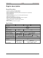
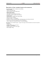
UL39Oi UL39OiS UL39Oisa Installation Manual MI 390A01 Revision No: 3 Date: 2014-09-15 Installation Manual MI 390A01 Revision No: 3 ULPOWER Date: 2014-09-15 UL390i UL390iS 390iSA Page: 3 of 69 Installation Manual ULPOWER UL390i UL390iS 390iSA Preface Thank you for deciding to use a ULPower engine. Before starting with the engine installation, read this Installation Manual carefully. The Manual will provide you with basic information on correct engine installation, a requirement for safe engine operation. If any passages of the Manual are not completely understood or in case of questions, please contact the manufacturer or an authorised dealer. We hope you will have much pleasure and satisfaction flying your aircraft powered by a ULPower engine. Remarks The figures in this Installation Manual show the typical construction. They may not represent in full detail or the exact shape of the parts which have the same or similar function. Specifications are given in the SI metric system with the USA equivalent in parenthesis. Where precise accuracy is not required, some conversions are rounded off for easier use. In addition to this Installation Manual, please refer to the following: Operating manual Maintenance Manual Illustrated Parts Catalogue Modifications The information and components/system descriptions contained in this Installation Manual are correct at the time of publication. ULPower, however, maintains a policy of continuous improvement of its products without imposing upon itself any obligation to install them on its products previously manufactured. ULPower reserves the right at any time to discontinue or change specifications, designs, features, models or equipment without incurring obligation. Please contact your dealer or check the manufacturers website (http://www.ulpower.com) for any updates or changes concerning the engine and its manuals. Engine serial number On all enquiries or spare parts orders, always indicate the engine serial number, as the manufacturer makes modifications to the engine for further development. The engine serial number is located on the top of the crankcase. MI 390A01 Revision No: 3 Date: 2014-09-15 Page: 4 of 69 ULPOWER Installation Manual UL390i UL390iS 390iSA Repeating symbols This manual uses the following symbols to emphasize particular information. These indications are important and must be respected. WARNING : Identifies an instruction which, if not followed, may cause serious injury including the possibility of death. Attention : Denotes an instruction which, if not followed, may severely damage the engine or other components. Note : Indicates supplementary information which may be needed to fully complete or understand an instruction. MI 390A01 Revision No: 3 Date: 2014-09-15 Page: 5 of 69 ULPOWER Installation Manual UL390i UL390iS 390iSA Safety Information The engine should only be installed and placed into operation by persons familiar with the use of the engine and informed with regard to possible hazards. This non-certified engine is designed for possible application on aircraft used in VFR conditions which have the capabilities of controlled gliding without engine power. It should be clear that the choice, selection and use of this particular engine on any aircraft is at the sole discretion and responsibility of the aircraft manufacturer, assembler and ULPower makes no warranty or representation on the suitability of its engine's particular aircraft. Furthermore, ULPower makes no warranty or representation of suitability with any other part, component or system which may be selected by manufacturer, assembler or user for aircraft application. owner/user. use on any this engine's the aircraft Use the appropriate tooling when installing the engine. Engine is delivered in "dry" condition (without oil). Before putting engine in operation it must be filled with oil according to specifications in the operating handbook. Never (test)run the engine without a propeller or flywheel as this will inevitably cause engine damage and present a hazard of explosion. Propeller/flywheel and its attachment with a moment of inertia in excess of the specified value must not be used and releases engine manufacturer from any liability. Improper engine installation and use of unsuitable piping for fuel-, cooling- and lubrication system releases engine manufacturer from any liability. Unauthorized modifications of engine or aircraft will automatically exclude any liability of the manufacturer for sequential damage. Do not use a protective device (e.g. a fuse) essential for the engine, to protect any other circuit Do not install unnecessary protective devices for the alternator and the regulator rectifier Install protective caps to protect switches essential to flight safety such as ECU switch, master switch, … MI 390A01 Revision No: 3 Date: 2014-09-15 Page: 6 of 69 Installation Manual ULPOWER UL390i UL390iS 390iSA Table of contents Preface ..................................................................................................................4 Remarks ............................................................................................................... 4 Modifications ......................................................................................................... 4 Engine serial number ............................................................................................... 4 Repeating symbols .................................................................................................. 5 Safety Information ....................................................................................................6 Table of contents .....................................................................................................7 Engine description ....................................................................................................9 General Description ................................................................................................ 9 Specifications ........................................................................................................ 9 Description of basic standard engine and accessories ...................................................... 10 Engine views ....................................................................................................... 11 Technical data ....................................................................................................... 15 Dimensions of basic standard engine ( With standard propeller flange L = 55 ) ...................... 15 Weight of basic standard engine and accessories ........................................................... 15 Centre of gravity of basic standard engine ................................................................... 15 Preparations for engine installation ............................................................................ 16 Transport ........................................................................................................... 16 State of delivery .................................................................................................. 16 Engine preservation .............................................................................................. 16 Engine suspension and position ................................................................................. 17 Mounting Position ................................................................................................. 18 Fuel injection system .............................................................................................. 20 Air intake system ................................................................................................... 28 Air filter ............................................................................................................ 28 Idle speed adjustment ........................................................................................... 28 Connecting the air filter ......................................................................................... 29 Throttle cable ....................................................................................................... 30 Exhaust system ...................................................................................................... 31 Dimensions of the exhaust system: ............................................................................ 31 Exhaust installation : ............................................................................................. 32 Cabin Heating: ..................................................................................................... 33 Cooling system....................................................................................................... 34 Cylinder head cooling: ........................................................................................... 34 Cylinder head temperature: .................................................................................... 34 Oil cooling: ......................................................................................................... 34 Oil temperature ................................................................................................... 34 Testing & evaluation ............................................................................................. 35 Lubrication system ................................................................................................. 36 Oil Cooler ........................................................................................................... 36 Oil/Air Separator & Breather (UL390i; UL390iS; UL390iSA) ............................................... 38 Oil/Air Separator & Breather (UL390iSA) ..................................................................... 40 Electrical system .................................................................................................... 41 1. Single ECU & Ignition .......................................................................................... 41 2. Double ECU & Ignition ........................................................................................ 48 Alternator & Regulator/Rectifier .............................................................................. 58 Recommended diagram .......................................................................................... 59 Starter motor ...................................................................................................... 60 Battery .............................................................................................................. 60 MI 390A01 Revision No: 3 Date: 2014-09-15 Page: 7 of 69 Installation Manual ULPOWER UL390i UL390iS 390iSA Additional wiring .................................................................................................. 60 Instruments .......................................................................................................... 61 Recommended Sensors ........................................................................................... 61 Propeller drive ...................................................................................................... 65 Propeller selection ................................................................................................ 68 Annex A ............................................................................................................... 69 Fuel header tank .................................................................................................. 69 MI 390A01 Revision No: 3 Date: 2014-09-15 Page: 8 of 69 ULPOWER Installation Manual UL390i UL390iS 390iSA Engine description General Description 4 stroke, 6 cylinder, horizontally opposed Electronic spark ignition (variable timing) Electronic multipoint fuel injection (pressure and temperature compensated) Electronic RPM limiter Direct propeller drive 7 bearing crankshaft with large thrust bearing (ball bearing type) Single central camshaft Push rods, Tappets and Over head valves Wet sump forced lubrication with integrated pressure regulator Ram air cooled cylinders and cylinder heads Integrated AC generator, external rectifier-regulator Electric starter Electric fuel pump and pressure regulator Specifications UL390i UL390iS Displacement: 3888cc Bore: 105.6 mm Stroke: Compression Ratio: 74 mm 8,16 : 1 Firing order: Direction of Rotation: Torque (ISA conditions): Power rating (ISA conditions): Basic standard engine weight: 9,1:1 1–4–5–2–3–6 Clockwise – Pilot's view – Tractor configuration 320Nm @ 2800rpm 140 hp @ 3300 rpm (130 hp @ 2800 rpm) 370Nm @ 2800 rpm 160hp @ 3300 rpm 160hp @ 3200 rpm (145Hp @ 2800 rpm) (145 hp @ 2800 rpm) 100kg (including starter motor and alternator) DC output: MI 390A01 Revision No: 3 100 kg 50 Amp Oil capacity: Fuel (unleaded): UL390iSA 4L MOGAS with min. 95 octane rating or AVGAS ( 95 octa = 87 mon = 97 AKI ) Date: 2014-09-15 MOGAS with min. 98 octane rating or AVGAS ( 98 Oct = 90MON = 94AKI ) Page: 9 of 69 Installation Manual ULPOWER UL390i UL390iS 390iSA Description of basic standard engine and accessories The basic standard engine consists of the following: Engine assembly Injectors and spark plugs Intake manifold, throttle and air filter Electric starter motor Integrated AC generator CPU, ignition coils and electrical wiring Fuel pump, pressure regulator and fuel lines Exhaust system Cooling ducts for cylinders and cylinder heads External rectifier-regulator Propeller flange L = 55 (Standard) In addition to the basic standard engine, following items are necessary accessories: Oil cooler and connections (depend on type of installation) Tacho, temperature and pressure sensors, wiring (and gauges) Only valid for the UL 390 iSA engine : engines of this type are delivered with an inverted oil system, containing : Gravity valve, Gravity oil pickup tube in the sump Gravity oil – air separator Breather adaptor on top of the engine Extra weight: 3,8 kg MI 390A01 Revision No: 3 Date: 2014-09-15 Page: 10 of 69 Installation Manual ULPOWER UL390i UL390iS 390iSA Engine views Figure 1 * dimensions for standard prop flange l = 55, different prop flanges are available (see page 64) MI 390A01 Revision No: 3 Date: 2014-09-15 Page: 11 of 69 Installation Manual ULPOWER UL390i UL390iS 390iSA Figure 2 MI 390A01 Revision No: 3 Date: 2014-09-15 Page: 12 of 69 Installation Manual ULPOWER UL390i UL390iS 390iSA Figure 3 MI 390A01 Revision No: 3 Date: 2014-09-15 Page: 13 of 69 Installation Manual ULPOWER UL390i UL390iS 390iSA Figure 4 MI 390A01 Revision No: 3 Date: 2014-09-15 Page: 14 of 69 ULPOWER Installation Manual UL390i UL390iS 390iSA Technical data Dimensions of basic standard engine ( With standard propeller flange L = 55 ) pos. (+) neg. (-) total max. dimension in x-axis 92.5 mm (3,641 inch) 630 mm (24,803 inch) 722.5 mm (28,444 inch) max. dimension in y-axis 327 mm (14,488 inch) 327 mm (14,488 inch) 654 mm (28,976 inch) max. dimension in z-axis 182 mm (7,165 inch) 290 mm (11,417 inch) 472 mm (18,582 inch) Weight of basic standard engine and accessories Dry weight of the basic standard engine from serial production: ........................... 85.3 kg (188 lb) The total operational weight depends on the accessories installed. Typical accessories provided by ULPower have the following weight: Ignition Coils & leads: ..............................................................................3,0 kg (6,6 lb) ECU & wiring loom: .................................................................................1,6 kg (3,5 lb) Exhaust, bolts, springs & seals: ..................................................................... 3,6 kg (8 lb) Electric fuel pump: .................................................................................0,7 kg (1,6 lb) Fuel filters (pre-filter & fine filter): .............................................................0.2 kg (0,4 lb) Oil/Air Separator & hoses: .........................................................................0,7 kg (1,5 lb) Rectifier Regulator: .................................................................................0.1 kg (0.2 lb) Rubber engine mounts: .............................................................................0.3 kg (0,7 lb) Optional Oil Cooler: ................................................................................... 1 kg (2,2 lb) 4 L engine lubricating oil:..........................................................................3.5 kg (7,7 lb) Possible fully operational engine weight: ..................................................... 100 kg (220.4 lb) Gravity valve, oil air separator and hoses: ................................................... 3.8 kg (8,37 lb) Possible fully operational engine weight for the UL390 ISA: ..............................103.8kg (228.8 lb) Centre of gravity of basic standard engine centre of gravity in x-axis -245.0 mm (-9,645” inch) centre of gravity in y-axis 0 mm (-0,0” inch) centre of gravity in z-axis -21 mm (-0.826” inch) . MI 390A01 Revision No: 3 Date: 2014-09-15 Page: 15 of 69 Installation Manual ULPOWER UL390i UL390iS 390iSA Preparations for engine installation Transport The engine is to be lifted by putting straps under the base of the cylinder heads on both sides of the engine (see pictures below). WARNING : Don’t lift the engine by the aluminium oil return tubes under the cylinders. State of delivery the engine will be delivered/shipped in a plywood crate with galvanised steel profiles and wooden runners. Engine preservation The engine is preserved at ULPower, thus warranting proper protection against corrosion for at least 12 months after date of delivery from ULPower. This warranty is subject to the following conditions: the engine must be stored in the packaging as supplied by ULPower. the coverings on various openings must not be removed. the engine has to be stored in a suitable (dry) place. If the engine is stored for longer than 12 months, the following tasks have to be performed every three months: crank the engine by hand on attachment screw of flywheel two complete turns anticlockwise (viewed alternator side). See figure 3. inspect for corrosion (e.g. prop shaft). At detection of corrosion, send the engine to the overhauler without delay. repack engine into original packaging and seal properly. WARNING : The engine must not be put into service during preservation. WARNING : The maximum storage period is limited to 24 months! Preservation for periods longer than 24 months is only possible after a written permission of ULPower. Should the situation arise, send the engine for inspection to ULPower. MI 390A01 Revision No: 3 Date: 2014-09-15 Page: 16 of 69 Installation Manual ULPOWER UL390i UL390iS 390iSA Engine suspension and position The UL390 engine has 4 mounting points situated at the back of the engine. 8 Rubber Mounts are provided with the engine; to be assembled on both sides of the 4 holes. (2) (1) The design of the engine mount must take into account the structural loadings, while ending with 4 pins to accommodate the rubber mounts. These should be tightened together with a M8x70 cap screw (8.8 Steel / Din 912) and lock nut between two flanges with the correct pretension (45mm distance)(Torque to 25Nm). We suggest the steel Engine Mount Pin (1) and aluminium Engine Mount Washer (2) to be dimensioned as below. This two parts are available as an option from ULPower if needed. MI 390A01 Revision No: 3 Date: 2014-09-15 Page: 17 of 69 Installation Manual ULPOWER UL390i UL390iS 390iSA Mounting Position Figure 5: Mounting points Y-axis MI 390A01 Revision No: 3 Z-axis attachment point 1 -125 mm 95 mm attachment point 2 125 mm attachment point 3 -125 mm 165 mm attachment point 4 125 mm 165 mm Date: 2014-09-15 95 mm Page: 18 of 69 Installation Manual ULPOWER UL390i UL390iS 390iSA As an option we can also provide a front engine mount plate. WARNING : The engine installation must be ground run tested before first flight. Prefabricated parts to weld to your frame are available as an option from ULPower if needed. MI 390A01 Revision No: 3 Date: 2014-09-15 Page: 19 of 69 ULPOWER Installation Manual UL390i UL390iS 390iSA Fuel injection system Accessories such as an electric fuel pump together with a pre-filter and fine fuel filter are provided in the basic package and the fuel pressure regulator is integrated in the engine assembly. A complete fuel connection kit can optionally be obtained from ULPower. We would like to draw your attention to a few points before installing/connecting the fuel system: Use appropriate fuel lines and connections as the fuel injection system requires a constant 3bar fuel pressure. A fuel injection system requires a return line of adequate dimensions. Large quantities (120 litres/hour = 31 USgal/h) of fresh fuel circulate through the fuel system of which only little is used and the remainder needs to return to the fuel tank. We strongly encourage the use of a fuel pressure sensor and gauge to verify fuel system is working correctly. Too much/little fuel pressure can influence the fuel mixture, possibly causing sudden stoppage or damage to the engine as a result. Overview The fuel is drawn from the fuel tank, through a pre-filter (100 micron), to the suction side of the fuel pump. From the pressure side, the fuel flows through a fine filter (15 micron), on to the injectors which inject the right amount of fuel into the inlet manifold. The remaining fuel passes through the pressure regulator, and returns to the fuel tank. If the aircraft is equipped with more than one fuel tank, which are not connected together, the return line must connect to the same fuel tank of which fuel is drawn from. There are 2 possibilities: install a 3 way duplex fuel selector valve which allows for 2 fuel lines to be switched simultaneously and has the provision to return the fuel to the same tank from which it is drawn. However never switch the selection to the “lock” position! install a small separate (± 2.5 lt / 0.7 USgal) header tank from which the fuel is drawn and also returned, while it is gravity fed from the separate fuel tanks. For ULP header tank, sea annex A For ease of explanation we presume the fuel system is connected to a single tank. Attention: In any case, do NEVER shut of the return line from the engine to the tank! This return line must always stay open. Installing Pre-filter and Fuel Pump The fuel pump (1) should be placed as close as possible to the fuel tank (3) as it is much more powerful on the pressure side than on the suction side. The pre-filter (2) is placed between fuel tank and pump to protect the fuel pump from being damaged by any foreign particles. MI 390A01 Revision No: 3 Date: 2014-09-15 Page: 20 of 69 Installation Manual ULPOWER UL390i UL390iS 390iSA Pump and pre-filter have the same size ending. A fuel hose with 12mm inner diameter should be used to connect fuel tank with pre-filter and pump to facilitate suction. Simple hose clamps may be used to tighten the hose as there shouldn't be any pressure build-up in this part or the fuel system. Verify that the inner diameter of the tube coming out of the fuel tank is not less than 8mm to ensure sufficient fuel flow to the pump. Also make sure that the position of the suction point in the fuel tank allows fuel to be sucked out of the tank in every conceivable flight situation or engine will stop running. Verify that the inner diameter from the return line is not less than 6 mm. A bracket to fix pre-filter and fuel pump and a bracket to fix the fine filter are included in the “fuel connection kit”. IN : M14 x1.5 OUT : M12 x 1.5 The + and - for the electrical connection is clearly marked. Use the appropriate wiring (2,5 mm²) together with a 15Amp fuse. A switch can be installed on the dashboard to provide electrical power to the pump allowing the pilot to manually switch the pump on/off. Alternately a relay switch (see picture on the right - obtainable from ULPower as an option) can be placed between the pump and Engine Control Unit (ECU), allowing the ECU to determine when the pump should start and stop. This feature has been added for ease of use and extra safety. Once power is supplied to the ECU it will automatically start the pump to build up pressure for about 1.5 seconds, after which it will shut down the pump (also saving on battery power) until the pilot engages the starter engine. Once the ECU detects the engine is turning, it automatically switches on the pump to provide fuel and leaves it on until it detects that the engine has been stopped. In the event of a crash landing and as a consequence an abrupt engine shutdown, the ECU will automatically shut off fuel pump to reduce the risk of fire. Electrical Wiring Diagram MI 390A01 Revision No: 3 Date: 2014-09-15 Page: 21 of 69 ULPOWER Installation Manual UL390i UL390iS 390iSA Optionally a second fuel pump can be installed as a backup. Ideally fuel should be drawn from tank through a second output on the tank, otherwise a T-Joint ø12x12x12 is placed between the tank and each pre-filter and is connected with the same hose and clamps. A non return valve is integrated in the pump/thread extension to prevent pressure loss. Important ! Provision should be made for a separate switch on the dashboard to interrupt power supply to the second (backup) pump. Experience has shown that leaving both pumps running simultaneously can cause one of the pumps to overheat due to insufficient fuel flow through the pump. This can result in a pump failure, eliminating backup if/when it is needed. Install an “or-or” switch to be sure that both pumps never can run together. Before take-off , make a test to be sure both pumps are working. A double fuel filter and bracket are included in the “extra fuel pump kit”. Attention: Be sure that all fuel lines and tank are very clean before start. No pump shall be replaced for claimed defects, where dirt is found into the pump, due to lack of fuel tank cleaning or pump filter replacement. Connecting fuel lines All fuel lines after the pump (except the return line) are under a constant 3bar pressure. Using the correct type and dimensions of fuel lines and connections is mandatory. We strongly advise against the use of simple hose clamps to connect these fuel lines. Our optional fuel connection kit provides the correct type of hoses and fittings. You have the choice between “press-on” or “reusable” type hoses and fittings The following overview shows how and in what order to connect all the fuel lines. It assumes the use of parts as provided in the fuel connection kit. In all cases (press-on or reusable) the engine is delivered with prepared an fitted connections as shown on picture 1. Picture 2 shows how to connect the rest of the fuel lines in case of single pump. Picture 3 shows how to connect in case of double fuel pump. MI 390A01 Revision No: 3 Date: 2014-09-15 Page: 22 of 69 Installation Manual ULPOWER Return line Connect to anti-return valve (E065001) UL390i UL390iS 390iSA Pressure side Connect line coming from “fuel fine filter” Picture 1 MI 390A01 Revision No: 3 Date: 2014-09-15 Page: 23 of 69 ULPOWER Installation Manual A) UL390i UL390iS 390iSA Press-on kit Picture 2 Picture 3 1 fuel from tank 2 fuel return to tank 3 1/8 NPT to connect “fuel pressure sensor” – see below 4 Connect to pressure side (Picture 1) 5 Connect to return line (Picture 1) Each fuel line connecting two parts is made as follows: Apply tape around the fuel hose at the point you wish to cut it to length. This way the galvanised steel braid will stay in position and doesn't unravel; a cleaner cut is obtained. Cut hose with a metal saw or grinding disc in such a manner that a straight end is obtained. Use compressed air to blow all particles of rubber and metal out of the inside of the hose. Remove the tape and slide a collet over each end of the hose including the steel braid. Fit the appropriate size banjo on each end all the way into the hose. Eventually use a little lubricating grease/saliva to ease assembly. Collet press tool Before pressing the collet over the hose, verify that hose and banjo are all the way in (there is a small hole in the collet to check). Turn/twist the banjo eye(s) in the desired direction depending on the installation. Use the collet press tool that is provided with the fuel connection kit to clamp the collet over the hose and banjo, by pressing the two halves together with a bench vice. MI 390A01 Revision No: 3 Date: 2014-09-15 Page: 24 of 69 Installation Manual ULPOWER UL390i UL390iS 390iSA Clean the fuel hoses extremely thoroughly to ensure no metal, rubber or other particles are inside before connecting all the lines. This is especially important as some of these tubes are down stream of both filters which means that the fuel injectors could be blocked by foreign particles which have not been removed properly. Use a copper sealing ring on both sides of a banjo and tighten with banjo bolt or hex cap nut. Do not over-torque (max. 25Nm) the bolts as this could cause damage to the aluminium thread in the connecting parts. A M12x1.5 banjo bolt with a 1/8"NPT thread in the head is used on the exit side of the fine fuel filter to connect a fuel pressure sensor. This bolt is also provided in the fuel connection kit. MI 390A01 Revision No: 3 Date: 2014-09-15 Page: 25 of 69 ULPOWER Installation Manual B) UL390i UL390iS 390iSA Reusable kit Picture 2 Picture 3 1 fuel from tank 2 fuel return to tank 3 1/8 NPT to connect “fuel pressure sensor” – see below 4 Connect to pressure side (Picture 1) 5 Connect to return line (Picture 1) Follow the instructions below to fix hoses and fittings: MI 390A01 Revision No: 3 Date: 2014-09-15 Page: 26 of 69 Installation Manual ULPOWER UL390i UL390iS 390iSA Use a copper sealing ring on both sides of a banjo and tighten with banjo bolt or hex cap nut. Do not over-torque (max. 25Nm) the bolts as this could cause damage to the aluminium thread in the connecting parts. An M12x1.5 banjo bolt with a 1/8"NPT thread in the head is used on the exit side of the fine fuel filter to connect a fuel pressure sensor. This bolt is also provided in the fuel connection kit. Remark The fuel pressure regulator is integrated in the right fuel block (between cylinders 3 and 5). It is connected to the inlet manifold with a cloth braided rubber tube and a small banjo (in front of starter motor) in order to regulate fuel pressure ±3 bar above inlet manifold pressure. Regularly check for wear (particularly on the parts where it might rub against the casing or inlet tubes) of this tube because if it has worn through, not only can the fuel pressure regulator not do its intended work, (regulating the fuel pressure to 3bar above the manifold pressure) but also the fuel mixture may become (too) lean and the idle speed may also increase because air could enter the manifold through another route instead of only through the throttle plate. Because of the extremely critical nature of the fuel system and fuel lines to the safe operation of the engine and aircraft, the inspection of all lines and its connections are mandatory before each flight. MI 390A01 Revision No: 3 Date: 2014-09-15 Page: 27 of 69 ULPOWER Installation Manual UL390i UL390iS 390iSA Air intake system The air intake system is specific designed for this engine. This system reduces the noise to an acceptable level on the intake side. Unless otherwise agreed this air intake system will be delivered as a standard part of the engine. Air filter Only ULPower approved air filters may be used. These air filters can be purchased by ULPower. Idle speed adjustment The throttle lever stop (1) is factory set to a position that should correspond to a warm engine idle speed of approx. 800 rpm. Attention: The idle speed of the engine should not be less than 700 rpm as rough turning could cause damage to the engine. We recommend a minimum of at least 800 rpm. With a cold engine, user should apply a little throttle so idle speed is at least 1000 rpm during warm-up. Only when engine is at operating temperature, minimum idle speed can be tested/set. WARNING: Adjusting idle speed should always be done while engine and master switch are switched off. WARNING: Take great care when adjusting throttle lever stop as the engine will be hot. If the warm idle speed of the engine is unsatisfactory, adjust as follows: If idle speed is too low: while engine is running apply throttle to the desired engine rpm. Set friction to keep throttle in position and turn off engine. Loosen throttle lever stop screws (3) with a 2.5mm Allan Key and move throttle lever stop (1) towards the left until it touches the throttle lever (2). Tighten throttle lever stop screws (3) to maximum 3 Nm (2.25 ft lbs). If idle speed is too high, firstly verify if throttle lever (2) is completely against the throttle lever stop (1). If not, stops of aircraft throttle system are not set correctly. Adjust according to aircraft manual or manufacturer. Otherwise loosen throttle lever stop screws (3) with a 2.5mm Allan Key and move throttle lever stop (1) a few mm towards the right. Tighten throttle lever screws (3) and test engine idle. Idle rpm will probably be too low; readjust as described above. A spring brings the lever back to “wide open”. This is for safety reason, in case of a broken cable. Note: Position : Throttle closed Do not leave throttle lever stop screws (3) loose while engine is running to test idle speed MI 390A01 Revision No: 3 Date: 2014-09-15 Page: 28 of 69 ULPOWER Installation Manual UL390i UL390iS 390iSA Connecting the air filter Separate, 3 parts shown in picture below are delivered with the engine. (Air filter, tube, flexible hose) Connect this parts as shown in picture below Because of the flexible hose, you can bend it the way you want. Fix the filter to the fuselage. Attention: Do not bend the hose more than 45°, otherwise you create obstructions for the airflow inside. Fix the filter on a place where fresh air can easy been suck-on. MI 390A01 Revision No: 3 Date: 2014-09-15 Page: 29 of 69 Installation Manual ULPOWER UL390i UL390iS 390iSA Throttle cable GOOD NOT GOOD Reason Because the engine moves against the firewall (because of rubber mounts) while running, the throttle position keeps on changing in case of “straight” throttle cable. This may lead to bad running and even engine stop ! MI 390A01 Revision No: 3 Date: 2014-09-15 Page: 30 of 69 Installation Manual ULPOWER UL390i UL390iS 390iSA Exhaust system Unless otherwise agreed, the motor will be delivered with the UL power exhaust system. The system is designed to reduce the noise to an acceptable level without loosing power. Dimensions of the exhaust system: 1 ) With muffler 2 ) With 3 in 1 collector MI 390A01 Revision No: 3 Date: 2014-09-15 Page: 31 of 69 Installation Manual ULPOWER UL390i UL390iS 390iSA Exhaust installation : The 6 exhaust tubes are fitted to the cylinder heads with 4 screws. Between the cylinder head and the flange is an exhaust gasket. (See Parts catalogue “Exhaust system“) Because ULP have to tighten the exhaust pipes during the final test run of your engine, the gaskets are deformed and have to be replaced. (6 spare parts are in the box) Procedure : Unscrew the 4 “M6” screws from each exhaust pipe. Replace the gasket by a new one. Refit the exhaust tube, but DO NOT TIGHTEN the screws! After the engine is installed in the plane, install the muffler. (Glide the exhaust tube in the muffler) Fix the muffler with the brackets to the engine and install the springs. Tighten the screws (24x) to fix the exhaust tubes to the cylinder heads. Installation muffler brackets : MI 390A01 Revision No: 3 Date: 2014-09-15 Page: 32 of 69 Installation Manual ULPOWER UL390i UL390iS 390iSA Cabin Heating: As an option we can also provide a cabin heating unit. For more information, see website accessories/parts, illustrated parts catalogue or contact ULPower. MI 390A01 Revision No: 3 Date: 2014-09-15 Page: 33 of 69 Installation Manual ULPOWER UL390i UL390iS 390iSA Cooling system Cylinder head cooling: Ram air ducts/chamber should guide the incoming air equally over the cylinders and cylinder heads. Sufficient amount of fresh air keeps the temperatures within the limits of operation. Describe ram air ducts and amount of air that should pass over the cylinders and cylinder heads. Cylinder head temperature: Max. : 180°C (356°F) Max. continuous: 160°C (320°F) Min.: 50°C (125°F) Oil cooling: Depending on the aircraft installation and climatic conditions it can be necessary to use an oil cooler. The oil cooler should be placed in fresh airflow. For further information we refer to the lubrication system description. Oil temperature Max.: Min.: Normal: 120°C (248°F) 50°C (122°F) 80-100°C (175-212°F) MI 390A01 Revision No: 3 Date: 2014-09-15 Page: 34 of 69 Installation Manual ULPOWER UL390i UL390iS 390iSA Testing & evaluation For new installations the pressure drop across both Ram air ducts must be checked. The following is a guide to evaluating an engine installation to see if it meets minimum cooling requirements. The easiest way to measure the air pressure drop across the engine and oil cooler is using a U tube manometer. It is basically a piece of clear tube with a inner diameter of 6 mm bent into a “U” and half filled with water. For Cylinder head air pressure, connect one side of the tube to a static port inside the ram air duct, and the other side of the tube inside the cowl near the outlet. For the pressure drop across the oil cooler plumb one side of the tube against the front of the cooler and fix the other side of the tube inside the cowl near the outlet. For the cylinder head cooling and oil cooling there have to be a pressure fall of at least 20 mm. at 120 km/h TAS. pressure fall Note: The tubes must be fitted in the same place each time to ensure you get consistent measurements. The change in air temperature is nearly the same as the change in CHT. If you do this test at 10°C but sometimes you want to fly at 30°C your CHT will be 20°C higher. MI 390A01 Revision No: 3 Date: 2014-09-15 Page: 35 of 69 ULPOWER Installation Manual UL390i UL390iS 390iSA Lubrication system Oil Cooler Depending on the aircraft and climatic conditions, an optional oil cooler will be necessary. A complete oil cooler kit is available from ULPower. The oil cooler can be connected on the interfaces of the sandwich plate with integrated thermostat which is situated at the front left side of the engine. Unscrew oil filter (1) and oil filter screw (2). Put the oil filter in a clean place so it can be reused - new oil filter is not provided with the oil cooler kit. The image below shows the items of the oil cooler kit and in what order they should be connected. (2) (1) The integrated thermostat shut of the oil flow to the oil cooler until the oil temperature reach ± 80° C (176 F). This is necessary to warm up the engine quickly in winter time. Connecting oil filter sandwich plate Insert the male adaptor bits (3) together with a copper sealing ring (4) into the oil filter sandwich plate with integrated thermostat (5) and gently tighten. A torque of max. 25Nm should be sufficient to ensure proper sealing. Place the sandwich plate where you unscrewed the filter; with the rubber seal facing towards the engine casing. Insert the oil filter adaptor screw (6) in engine casing through the sandwich plate. Rotate sandwich plate to desired position and tighten screw with spanner (again a torque of max. 25Nm should be sufficient). Lubricate the oil seal of the filter a little and screw filter onto the sandwich plate. The filter should only be tightened by hand. MI 390A01 Revision No: 3 Date: 2014-09-15 Page: 36 of 69 Installation Manual ULPOWER UL390i UL390iS 390iSA Positioning oil cooler The standard oil cooler provided with the oil cooler kit has a matrix width of 235mm and is 13 rows high. If necessary, other sizes are available from ULPower upon request. Install the oil cooler in a place where cold outside air is forced through the cooler. For the best results be sure to guide the air to the cooler and that all air can only go through the cooler and not escape around it! The oil cooler can be placed in any direction (horizontal, vertical, upside down, …), whatever suits best to obtain a good and neat looking installation. Depending on where the cooler will be installed, you will need to make some brackets to attach the cooler to engine or aircraft. We strongly advise to use rubber dampers so that it is less subject to vibrations, which otherwise could cause cracks and leakage. 3 brackets and 4 silent blocks are included in the “oil cooler kit” to fix the cooler in front of the engine (see picture below) Of course it’s allowed to fix the cooler on any other place, but be sure that there is enough air flow over the cooler (see “testing & evaluation page 29) Attention: It’s customer responsibility to install an oil cooler efficient enough to cool the engine. Assembling oil lines When sandwich plate and oil cooler are in place, the aluminium hose fittings can be screwed on to measure the correct length of oil line needed. Take into account that he minimum bend radius of the hose is 90mm (3.5inch). You have the choice to use “reusable” or “push-on” oil lines and fittings (see website: “accessories/kits section). In any case: one straight, one 45°, one 90° and one 150° fitting are provided with the oil cooler kit. If necessary (for ease of installation) different angles can be obtained from ULPower upon request. Available angles: MI 390A01 Revision No: 3 Date: 2014-09-15 Page: 37 of 69 ULPOWER Installation Manual 0° 45° 90° UL390i UL390iS 390iSA 120° 150° 180° Instruction to fix the reusable hoses and fittings: see page 23 Instruction to fix the push-on hoses and fittings: see page 24 Connecting oil lines Connect oil lines to the sandwich plate and the oil cooler. There is no particular in/out direction on the cooler so you are free to connect them in the most suitable way. Gently tighten with a spanner to ensure proper sealing. There is no need to pull as hard as you can and as a result possibly damaging thread or connections. End note When engine is completely installed and is started up for the very first time, check for leaks in the oil cooler assembly. Tighten where necessary. Oil/Air Separator & Breather (UL390i; UL390iS; UL390iSA) A breather tube is provided on the engine (picture 1). Connect this tube with provided hose to the oil /air separator. An “oil return tube” is also provided on the engine (picture 2). Connect this tube with the provided hose to the “return” side of the oil/air separator. The breather on an engine is necessary to prevent any pressure build-up inside the engine casing due to normal leakage of blowby gases through the piston ring gaps. It lets the air or over-pressure escape from the engine through a tube into the free air (outside the aircraft). In most circumstances the breather not only pushes out air, but is also very likely to blow out some oil that is scattered around inside the engine. To prevent too much oil (or any at all) being lost and blown out into the free air, an oil/air separator is connected to the breather. The oil/air separator is provided with the engine and "filters" out oil and lets it return to the engine before the air leaves the aircraft. Picture 1 MI 390A01 Revision No: 3 Picture 2 Date: 2014-09-15 Page: 38 of 69 ULPOWER Installation Manual UL390i UL390iS 390iSA The oil/air separator bottle is connected as follows: Connect to tube leaving aircraft Connect to tube coming from engine Connect to tube returning to oil sump The oil/air separator bottle can be mounted onto the firewall and must stay in its upward position as shown above. It should be positioned as high up as possible, at least above the centre of the crankshaft. Both hoses can be cut to length as required to have a clean installation. Make sure the hose coming from the engine (emerging on the top of the engine, coming from between the cylinders) goes straight into the oil/air separator and the hose returning to the oil sump follows a nice line going downwards to the sump. There should be no "bucket" bend in the hoses enabling oil to stay in the hose. Be sure to keep the return line to the oil sump away from the exhaust; eventually use some shielding. If for any reason or after a time period specified in the maintenance manual the hose must be replaced, be sure to use the correct type. It must be fit for oil and must be able to withstand a temperature of at least 120°C (250°F). If not, oil line might melt and all oil will leak from engine! MI 390A01 Revision No: 3 Date: 2014-09-15 Page: 39 of 69 Installation Manual ULPOWER UL390i UL390iS 390iSA Oil/Air Separator & Breather (UL390iSA) For the installation of the oil/air separator on the UL390iSA (aerobatic), with the gravity valve and all oil lines, follow the instructions below. It is important that the gravity valve and the oil/air separator are mounted exactly vertically ! MI 390A01 Revision No: 3 Date: 2014-09-15 Page: 40 of 69 ULPOWER Installation Manual UL390i UL390iS 390iSA Electrical system The engine is delivered with the “ECU Wiring loom engine” installed. Wires and connecters which have to be connected during the installation are explained below The ECU and the “ECU wiring loom cockpit” are delivered separate. 1. Single ECU & Ignition 1 2 3 4 5 6 7 ECU Wiring loom engine 1. 2. 3. 4. 5. 6. 7. Connect to ECU Ground for cable shielding PC Connector (UL check or aux box) Connect to coil 1 Ground Connect to coil 2 Ground ! The standard length of the wiring loom is 500 mm. This means that, if you want to install the ECU on the firewall, the maximum distance between back plate engine and firewall is 400 mm. Optionally a longer wiring loom is available. MI 390A01 Revision No: 3 Date: 2014-09-15 Page: 41 of 69 ULPOWER Installation Manual UL390i UL390iS 390iSA ECU Wiring loom cockpit 1. Blue shrink sleeve : Battery - / Put all 5 wires together 2. Red shrink sleeve : Battery + / Put all 6 wires together to a switch, install a fuse 20A and use a wire from minimum 2.5mm² (14AWG) 3. Green shrink sleeve : “+” and “-“ to optional fuel pump relay 4. Brown shrink sleeve : Ignition switches : white/blue and white/white to ignition switch coil 1 white/blue and white/red to ignition switch coil 2 Attention: Open contact = coil ON ! Closed contact = coil OFF ! 5. Grey shrink sleeve : 3 wires : white/white : RPM signal (2 pulses/ rev. 0 – 12V) white/blue : Fuel consumption (Injector puls). Output is a duty cycle. 100% is equal to 72l/Hr white/red : fuel consumption (pulses/litre) 72l/Hr = 170Hz (170 pulses/sec) 6. Yellow shrink sleeve : 4 wires : white/green : Common (-) white/red : warning signal in case of ECU over temperature (not used) white/blue : warning signal in case of battery low (<12.5V) white/white : check light : When the engine run correctly, the led doesn’t light up. When there is a problem with one of the following sensors, the led light up. a) Oil temperature sensor b) Inlet air temperature sensor c) Throttle position sensor d) Altitude sensor (Integrated in ECU) 7. Ground for cable shielding 8. PC Connector for data transmission 9. Connect to the ECU MI 390A01 Revision No: 3 Date: 2014-09-15 Page: 42 of 69 ULPOWER Installation Manual UL390i UL390iS 390iSA ECU Electrical Wiring Diagram for single ECU MI 390A01 Revision No: 3 Date: 2014-09-15 Page: 43 of 69 Installation Manual ULPOWER UL390i UL390iS 390iSA Aircraft wiring UL Power propose to install the aircraft wiring as explained below. The 2 switches for the fuel pump must be connected to each other that way that it is not possible to run both pumps together. UL Power offer this pre-wired display. (See pictures) MI 390A01 Revision No: 3 Date: 2014-09-15 Page: 44 of 69 Installation Manual ULPOWER UL390i UL390iS 390iSA Pre-wired display (E081550). For more info, contact UL Power MI 390A01 Revision No: 3 Date: 2014-09-15 Page: 45 of 69 Installation Manual ULPOWER UL390i UL390iS 390iSA Detailed diagram, for maintenance only MI 390A01 Revision No: 3 Date: 2014-09-15 Page: 46 of 69 ULPOWER Installation Manual UL390i UL390iS 390iSA Connection “ECU wiring loom cockpit”, for maintenance only Pos AWG Signal Pin Remark 1 20 Switch off ignition 1 A White/white 2 20 Switch off ignition 2 T White/red 3 20 Switch off common U White/Blue 4 20 RPM f White/White 5 20 Consumption pulse/litre j White/red 6 20 Consumption inj. pulse g White/blue 7 20 Common - W White/green 8 20 Sensor fail Y White/white 9 20 ECU over temperature Z White/red 10 20 Battery low G White/blue 11 20 Fuel pump relay - J White/blue 12 20 Fuel pump relay + e White/white 13 20 Health h White/red 14 20 Engine data TX232 B White/blue 15 20 Engine data common C White/white 16 20 12 V Battery injectors c 17 20 12 V Battery injectors N 18 20 12 V Battery + P 19 20 12 V Battery + R 20 20 12 V Battery + S 21 20 12 V Battery + d 22 20 12 V Battery - K 23 20 12 V Battery - L 24 20 12 V Battery - M 25 20 12 V Battery - a 26 20 12 V Battery - b Common V Common X Proc RST cntr H Engine data out A D Engine data out B E Engine data out common F MI 390A01 Revision No: 3 Date: 2014-09-15 future Page: 47 of 69 Installation Manual ULPOWER UL390i UL390iS 390iSA 2. Double ECU & Ignition For safety reason we offer a completely redundant, dual channel ECU combination. In this case the engine is equipped with double oil temp sensors, double air intake temp sensors, double throttle pos sensors, double hall sensors, double wiring loom and double ECU. The engine is delivered with 2 x “ECU wiring loom – engine” installed (Picture 1). Wires and connections which have to be connected during installation are explained below. 2 ECU – boxes and 2 x “ECU wiring loom – cockpit” are delivered separate. ECU Wiring loom engine 1. 2. 3. 4. 5. Connect to ECU Ground for cable shielding PC Connector (UL check or aux box) Connect to coil Ground MI 390A01 Revision No: 3 Date: 2014-09-15 Page: 48 of 69 ULPOWER Installation Manual 1. Blue shrink sleeve : Battery - / Put all wires together UL390i UL390iS 390iSA ECU Wiring loom engine cockpit 2. Red shrink sleeve + ECU : Battery + / Put all 4 wires together 3. Red shrink sleeve + injection : Battery + / Put the 2 wires together Attention: Do not connect 2 en 3 together to the same +12V ! Use separate switches! 4. Green shrink sleeve : “+” and “-“ to optional fuel pump relay 5. Grey shrink sleeve : 3 wires : white/white : RPM signal (2 pulses/ rev. 0 – 12V) white/blue : Fuel consumption (Injector pulse). Output is a duty cycle. 100% is equal to 72l/Hr white/red : fuel consumption (pulses/litre) 70l/Hr = 170Hz (170 pulses/sec) 6. Yellow shrink sleeve : 4 wires : white/green : Common (-) white/red : warning signal in case of ECU over temperature (not used) white/blue : warning signal in case of battery low (<12.5V) white/white : check light : When the engine run correctly, the led doesn’t light up. When there is a problem with one of the following sensors, the led light up. a) Oil temperature sensor b) Inlet air temperature sensor c) Throttle position sensor d) Altitude sensor (Integrated in ECU) 7. Ground for cable shielding 8. PC Connector for data transmission 9. Connect to ECU MI 390A01 Revision No: 3 Date: 2014-09-15 Page: 49 of 69 Installation Manual ULPOWER UL390i UL390iS 390iSA ECU Electrical Wiring Diagram for double ECU MI 390A01 Revision No: 3 Date: 2014-09-15 Page: 50 of 69 Installation Manual ULPOWER UL390i UL390iS 390iSA Aircraft wiring UL Power propose to install the aircraft wiring as explained below. The 2 switches for the fuel pump must be connected to each other that way that it is not possible to run both pumps together. UL Power offer this pre-wired display. (See pictures) MI 390A01 Revision No: 3 Date: 2014-09-15 Page: 51 of 69 Installation Manual ULPOWER UL390i UL390iS 390iSA Pre-wired display (E081565). For more info, contact UL Power MI 390A01 Revision No: 3 Date: 2014-09-15 Page: 52 of 69 Installation Manual ULPOWER UL390i UL390iS 390iSA Detailed diagram, for maintenance only MI 390A01 Revision No: 3 Date: 2014-09-15 Page: 53 of 69 ULPOWER Installation Manual UL390i UL390iS 390iSA Connection “ECU wiring loom cockpit”, for maintenance only Pos AWG Signal Pin Remark 1 2 3 4 20 RPM f White/White 5 20 Consumption pulse/litre j White/red 6 20 Consumption inj. pulse g White/blue 7 20 Common - W White/green 8 20 Sensor fail Y White/white 9 20 ECU over temperature Z White/red 10 20 Battery low G White/blue 11 20 Fuel pump relay - J White/blue 12 20 Fuel pump relay + e White/white 13 20 Health h White/red 14 20 Engine data TX232 B White/blue 15 20 Engine data common C White/white 16 20 12 V Battery injectors c 17 20 12 V Battery injectors N 18 20 12 V Battery + P 19 20 12 V Battery + R 20 20 12 V Battery + S 21 20 12 V Battery + d 22 20 12 V Battery - K 23 20 12 V Battery - L 24 20 12 V Battery - M 25 20 12 V Battery - a 26 20 12 V Battery - b Common V Common X Proc RST cntr H Engine data out A D Engine data out B E Engine data out common F MI 390A01 Revision No: 3 Date: 2014-09-15 future Page: 54 of 69 Installation Manual ULPOWER UL390i UL390iS 390iSA ULPower advise to use “positive lock” connectors for all electrical connections to ensure that connection not become loose because of vibrations. Make sure ECU and Ignition switches are of adequate quality and are designed for at least 20 Amp DC current. The reason for this is that DC current tends to create a spark each time you switch, which deteriorates the contact points and can cause cheap/low quality switches to fail in time. Mount the ECU unit in a place where temperatures do not reach over 65°C (preferably on the cabin side of the firewall). Take great care when putting the wiring loom through the firewall not to damage the wiring. Use rubber around the hole and the wiring loom to protect it when installed. Mount the Ignition coils on the firewall or the engine mount (on a flat surface). We advise not to mount them right beside the ECU to avoid any possible electrical disturbance. Also don’t mount them on a place where vibrations are generated, this leads to loose contacts inside the coil. The distance between ignition coils and ECU must be at least 100 mm. Also the distance between each of the eight cables and the ECU must be at least 100 mm. MI 390A01 Revision No: 3 Date: 2014-09-15 Page: 55 of 69 Installation Manual ULPOWER UL390i UL390iS 390iSA Connect connectors on wiring loom as shown below to any of the two coils. Make up the ignition leads according to the length needed. The necessary parts (covers, clamps and lead) are provided with the engine. MI 390A01 Revision No: 3 Date: 2014-09-15 Page: 56 of 69 Installation Manual ULPOWER UL390i UL390iS 390iSA The provided copper clamps are used on one end of each lead and screw into the ignition coil cover. Strip only a few millimetres of the outer plastic of the ignition lead to unveil the inner core. It is advisable to solder the copper clamp onto the lead for good contact. The ignition lead is held and guided behind the point of soldering so no bending and as a result cracking should occur on the soldering. Push in the lead with the clamp all the way into the ignition coil cover and then screw on the cover with a couple of turns. Make sure the lead is fixed tightly and it cannot be pulled out by a small force. The ignition coil cover clicks onto the ignition coil. Make sure you get the correct leads going to the correct spark plugs. The other side of the lead is screwed in the spark plug cover. Cut the lead to the requested length. Do not strip the plastic, but screw the spark plug cover into it. Do not forget to first slide the rubber sealing over the lead before attaching it to the spark plug cover. When attached pull back the rubber to cover the joint and make it moisture proof. Slide the bottom rubber over the spark plug cap and click the cap onto the corresponding spark plug. Each cylinder head has 2 spark plugs; each going to a different coil for redundancy. Cylinder numbering is done from the propeller backwards. See numbering below. MI 390A01 Revision No: 3 Date: 2014-09-15 Page: 57 of 69 ULPOWER Installation Manual UL390i UL390iS 390iSA Attention: First start after installation / maintenance. Start the engine with only coil 1 (and ECU 1 in case of redundancy ) When the engine run very well, stop the engine and start again with only coil 2 (and ECU 2 in case of redundancy ) When the engine run very well, you can run with both coils together. (ECU1 and ECU2 in case of redundancy If you have made a mistake and connect an ignition cable to the wrong spark, you can damage the engine. That’s why you have to test both coils separate. Alternator & Regulator/Rectifier Attention ! Because the ULP engine needs continue power to the ECU to run, it’s very important that current is available at any moment. We strongly advise to use a good battery and to measure the voltage. Also install a warning system to warn the pilot if the voltage drops below 12,5 VDC. When the alternator fails, you are able to fly another 40-45 minutes with a good and full charged battery. Note: while starting the engine in cold weather, the voltage can drop temporal under 12V and generate a warning signal. When the alternator work properly, the warning signal must disappear after 10-20 sec while running at 1500 Rpm or higher. Do not install unnecessary protective devices for the alternator and the regulator rectifier. The UL390 has a permanent magnet 3-phase alternator (1) integrated at the back of the engine. It provides current to all connected electrical consumers and/or charges the battery. The AC output from the alternator is converted and regulated into approximately 14.8V DC by an external regulator/rectifier that is provided with the engine. The regulator must be installed on the firewall with 2 bolts M 6. Take care that the regulator can not overheat. We recommend to place him on a place where fresh air can flow over the cooling fins. Plug the connector (2), coming from the alternator in the regulator (3) and lock it. A cable to connect the regulator with the battery is separate delivered. Plug this cable in the regulator(4). If you need an extension for the wires regulator – battery, use wires with a cross section of at least 6 mm² (10 AWG) MI 390A01 Revision No: 3 Date: 2014-09-15 Page: 58 of 69 Installation Manual ULPOWER UL390i UL390iS 390iSA Recommended diagram We advise to install a capacitor 68.000 µF (ULP n° E053010) parallel on the battery to ensure power to the +12V bus in case of open contact in the battery. Optional switch can be placed on showed position if customer want to disconnect the alternator from the system. MI 390A01 Revision No: 3 Date: 2014-09-15 Page: 59 of 69 ULPOWER Installation Manual UL390i UL390iS 390iSA Starter motor The electric starter engine (1) is mounted on the top of the engine and drives the ring gear (2) at the back of the engine. The motor is activated by engaging the starter button (the master switch has to be on) which trips the integrated solenoid (3), hence current flows from the battery to the motor. STARTER MOTOR (3 ) 1,2kW STARTER BUTTON 12V DC BUSBAR (1 ) (2 ) START SOLENOID FUSE 30A MASTER SWITCH + - BATTERY Connect the plus terminal coming from the battery to the solenoid (see image below left) with a cable of at least 25mm² (3AWG). Use an M8 lock nut. Wiring for the starter button should be at least 1.5mm² (14AWG or smaller). Make sure to insulate both connections to prevent short circuit by touching with a metal object and making contact with the engine/ground! Ignition Button (+) Battery (+) Ground to starter motor and solenoid is provided via engine block. Ground cable is attached to engine mount plate with an M6 bolt (see image above right). Cable thickness should be at least 16mm² (5AWG or smaller). Battery In a standard installation there has to be one battery of 12V/18Ah. Additional wiring The ECU (Engine Control Unit) used for the UL390 engine has been specially developed, and thoroughly tested. Every possible "over voltage" or short-circuit has been simulated to be sure that the ECU goes on working in every condition. However, for extreme safety, we offer a completely redundant, dual channel ECU combination. (See page 45) MI 390A01 Revision No: 3 Date: 2014-09-15 Page: 60 of 69 Installation Manual ULPOWER UL390i UL390iS 390iSA Instruments Recommended Sensors In order to operate the engine within the specified limits of the operating handbook, operator should at least monitor following parameters: RPM Oil Pressure Oil Temperature Fuel Pressure CHT EGT (optionally) Manifold Pressure (optionally) Battery Voltage Amp (optionally) UL Power offers different sensors. You will find more information on the parts and accessories list. RPM The ECU unit has a pulsed output which gives two (2) pulses per revolution. Any instrument that can use a 12V pulse can be connected to the ECU for RPM reading. Oil Pressure & Oil Temperature Oil pressure and temperature are both important figures to monitor and should be kept within operating limits at all times. Therefore an oil pressure sensor and oil temperature sensor should be installed on the engine and (analogue or digital) gauges installed on the aircraft's dashboard. Make sure sensors and gauges are compatible and properly calibrated. Recommended specifications for oil pressure sensor: range: 0-10 bar (0-150 psi) thread : 1/8"NPT Recommended specifications for oil temperature sensor: range: up to at least 130°C (266°F) thread: 5/8"-18 UNF or M10 ; M10x1 ; M12x1.5 ; 1/8 NPT if adaptor plug (option) is used The oil and fuel pressure sensors shown are passive analogue sensors of the resistive type. Active 12V solid state sensors are more expensive but are much less sensitive to vibration and therefore more reliable. However only certain instruments will accept active pressure sensors. MI 390A01 Revision No: 3 Date: 2014-09-15 Page: 61 of 69 Installation Manual ULPOWER UL390i UL390iS 390iSA Oil Pressure The oil pressure sensor should not be directly screwed into the engine block, and is therefore connected by means of a flexible pressure line in order to avoid sensor failure due to engine vibrations. The sensor can be attached to the engine mount frame or the firewall. Oil pressure is measured in the main oil gallery at the left side of the engine casing, where M10x1 thread is foreseen. Interface for oil pressure sensor (Cockpit) An oil pressure sender line kit consisting of 1m Stainless Braided PFE Hose, Oil Pressure Sensor Adaptor (2), Banjo (3) with Banjo Bolt (4) and Copper Sealing Rings (5) comes with the engine. The length of the line will depend on where you would like to install the sensor. Determine the length and assemble the line as follows: Apply tape around the hose at the point you wish to cut it to length. This way the stainless steel braid will stay in position and doesn't unravel; a cleaner cut is obtained. Cut hose with a metal saw or grinding disc in such a manner that a nice straight end is obtained. Unscrew the socket screw (4) of the oil (6) pressure sensor fitting (6). Be careful not to (5) (4) loose the brass cone (5) that sits inside. Before removing the tape, slide the socket screw over the hose including the stainless steel braid. Remove the tape. Open the stainless steel braid towards the outside to free the end of the inner plastic tube. As shown on the image above. Do not unravel the braid too much. Slide/push the brass cone (5) over the plastic tube all the way to the end. Push the oil pressure sensor adaptor fitting (6) into the tube. Pull back the socket screw towards the fitting and screw onto the fitting as far as possible. Make sure the steel braid does not go in between the thread. Use two spanners - one to hold fitting, the other to tighten the lock screw. Repeat on other side with the banjo fitting. Clean the oil pressure line thoroughly to ensure no metal, rubber or other particles are inside before connecting the line. Once oil line is assembled, connect it to the engine. Tighten banjo bolt and washers to ensure proper sealing. However, be careful not to damage thread in casing by over tightening the banjo bolt (max. 25Nm torque). MI 390A01 Revision No: 3 Date: 2014-09-15 Page: 62 of 69 Installation Manual ULPOWER UL390i UL390iS 390iSA Oil Temperature The oil temperature is measured on the left side of the crankcase. (See picture) A temperature sensor with 5/8"-18 UNF thread combined with a sealing ring can be screwed into the front. This sensor will indicate the oil temperature in the cockpit. Sensors with M10; M10x1; M12x1,5 or 1/8 NPT thread can also be used with an adaptor plug. These adaptor plugs are available from ULPower if needed. (See accessories/parts) Interface for oil temperature sensor (cockpit) Make sure nuts/sensors are properly sealed, making sure that the oil can’t leak of the engine! Fuel Pressure Recommended specifications for fuel pressure sensor: range: 0-5 bar (0-80 psi) thread: 1/8"NPT (4) CHT Ideally all 4 CHTs should be measured. Alternately at least 2 CHTs (the hottest one on each side of the engine; most probably CYL3 and CYL4 in a tractor configuration) should be monitored and kept within limits. CHT Bayonet style probes by ULPower are recommended. See accessories/kits. Bayonet adaptor (3/8"UNF) is integrated. Each cylinder head has a pre-drilled hole close to the exhaust port to monitor CHT. Alternately 14mm gasket ring type CHT-probes can be used under sparkplugs, but cooling air flow over the cylinder heads can give different readings when compared to CHT probes which are sunk into the cylinder head material. MI 390A01 Revision No: 3 Date: 2014-09-15 Page: 63 of 69 Installation Manual ULPOWER UL390i UL390iS 390iSA Attention : It is recommended to measure all cylinder heads as temperatures can fluctuate according to the airflow over the cooling fins. Checking the individual temperatures can also give an indication of arising problems so precautionary measures can be taken. EGT Although one cannot do much (apart from changing the throttle) on the ULPower engine to influence the EGT, monitoring all EGTs will provide the pilot with an immediate indication that things might not be normal. If one EGT reading becomes substantially higher or lower, this is an indication that something is wrong. A higher than normal EGT could mean less fuel (leaner and hotter mixture) is being supplied - which could be caused by a partially blocked fuel injector. Perhaps there is a leak in the induction manifold and extra air is being drawn into this cylinder making its mixture leaner and hotter. Lower than normal EGTs are indicative of richer than normal fuel mixtures. This could be caused by a fuel injector which does not close completely in between cycles, or a blockage in the inlet manifold causing less air to be drawn into the cylinder. Measuring one EGT can only tell you that that specific cylinder is running properly or not. It might be wrong to conclude that what you measure is representative for all cylinders. No holes are predrilled in the exhaust so you are free to choose the type you prefer (probes with clamps or thread), however we recommend to use the ULPower EGT probes. See accessories/kits. Usually temperatures are measured roughly 7cm ( 3in ) from the beginning of the exhaust piping. Manifold Pressure A MAP sensor can optionally be installed to give you an indication of how much power you are actually using. The power produced is a function of the MAP and engine rpm. A suitable flexible hose connected to a MAP sensor can be attached to the manifold with a double banjo to the inlet collector, (option) instead of the single one supplied for the fuel pressure regulator. Battery Voltage Battery voltage will indicate if the alternator is working properly. If it is charging, the voltage should be above 14V. If you are consuming more that what the alternator can deliver or in the rare event the alternator or regulator/rectifier has failed, the battery voltage will drop. If voltage goes below 12V be warned and land as soon as possible. Engine will stop once battery voltage goes below 10V! Electrical Current An amp meter can also be installed to precisely measure the amount of electrical current the alternator is delivering. MI 390A01 Revision No: 3 Date: 2014-09-15 Page: 64 of 69 Installation Manual ULPOWER UL390i UL390iS 390iSA Propeller drive The UL520 is a direct drive engine. The propeller is mounted on the propeller flange which is directly connected to the crankshaft; no gearbox or belt reduction is used. The propeller flange is fixed to crankshaft with a splined connection to take the torque loads and is held in position by a single central bolt. The bolt is locked with a special locking washer. A large ball bearing is used as thrust bearing which is held in position by two disc springs and a spacer ring. This assembly allows engine to be used in either tractor or pusher configuration. Engine turns clockwise when seen from cockpit in tractor configuration. The propeller must be carefully selected to match the airframe and the engine characteristics. The hub of the propeller must be drilled with holes to match the flange. 6 propeller drive lugs are provided with the engine. These are made to have a tight fit in the propeller flange holes. ULPower offers different types of propeller flanges. 1. Standard Flange MI 390A01 Revision No: 3 Date: 2014-09-15 Page: 65 of 69 Installation Manual ULPOWER UL390i UL390iS 390iSA 2. SAE I - F – Flange : E022550 L055 / E022550 L090 / E022550 L110 = assembly 3. SAE VI - B – Flange : E022551 L055 / E022551 L090 / E022551 L110 = assembly MI 390A01 Revision No: 3 Date: 2014-09-15 Page: 66 of 69 Installation Manual ULPOWER UL390i UL390iS 390iSA 4. SAE VI - C – Flange : E022552 L055 / E022552 L090 / E022552 L110 = assembly 5. SAE VI - D – Flange : E022553 L055 / E022553 L090 / E022553 L110 / E022553 L035 = assembly MI 390A01 Revision No: 3 Date: 2014-09-15 Page: 67 of 69 ULPOWER Installation Manual UL390i UL390iS 390iSA Propeller selection Propeller with Rotational Moment of Inertia of up to 0.6kgm² has been used with no known problems up to date. An all wooden propeller is recommended to absorb engine vibrations. However a few composite propellers have been used with no known problems up to date. WARNING : Never use the engine without a propeller. Damage will occur in this state. In case of using a ‘constant speed propeller”, only an electrically commanded propeller can be used. ULPower can optionally deliver a bracket to mount the electrical contacts. Part n° E022007 Install the bracket as show in the picture. Starting from these you have to build up another bracket according to your propeller and the electrical contacts. MI 390A01 Revision No: 3 Date: 2014-09-15 Page: 68 of 69 Installation Manual ULPOWER UL390i UL390iS 390iSA Annex A Fuel header tank MI 390A01 Revision No: 3 Date: 2014-09-15 Page: 69 of 69