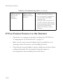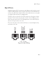
1
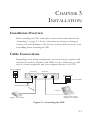
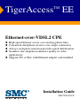
TigerAccess™ EE
Ethernet-over-VDSL2 CPE
◆
◆
◆
◆
High-speed Internet access over existing phone lines
Concurrent data/phone services over single connection
Always-on digital connection provides quick initialization
Seamless rate adaptation enhances quality in video
applications
◆ Supports PC or Mac with Ethernet adapter card installed
Installation Guide
SMC7800A/VCP
TigerAccess-EE CPE
Installation Guide
From SMC’s Tiger line of feature-rich workgroup LAN solutions
20 Mason,
Irvine, CA 92618
Phone: (949) 679-8000
February 2007
Pub. # 150200004100H
Information furnished by SMC Networks, Inc. (SMC) is believed to be accurate and reliable. However, no
responsibility is assumed by SMC for its use, nor for any infringements of patents or other rights of third
parties which may result from its use. No license is granted by implication or otherwise under any patent or
patent rights of SMC. SMC reserves the right to change specifications at any time without notice.
Copyright © 2007 by
SMC Networks, Inc.
20 Mason
Irvine, CA 92618
All rights reserved. Printed in Taiwan
Trademarks:
SMC is a registered trademark; and EZ Switch, TigerAccess, TigerStack and TigerSwitch are trademarks of
SMC Networks, Inc. Other product and company names are trademarks or registered trademarks of their
respective holders.
LIMITED WARRANTY
Limited Warranty Statement: SMC Networks, Inc. (“SMC”) warrants its products to be
free from defects in workmanship and materials, under normal use and service, for the
applicable warranty term. All SMC products carry a standard 90-day limited warranty from
the date of purchase from SMC or its Authorized Reseller. SMC may, at its own discretion,
repair or replace any product not operating as warranted with a similar or functionally
equivalent product, during the applicable warranty term. SMC will endeavor to repair or
replace any product returned under warranty within 30 days of receipt of the product.
The standard limited warranty can be upgraded to a Limited Lifetime* warranty by registering
new products within 30 days of purchase from SMC or its Authorized Reseller. Registration
can be accomplished via the enclosed product registration card or online via the SMC Web
site. Failure to register will not affect the standard limited warranty. The Limited Lifetime
warranty covers a product during the Life of that Product, which is defined as the period of
time during which the product is an “Active” SMC product. A product is considered to be
“Active” while it is listed on the current SMC price list. As new technologies emerge, older
technologies become obsolete and SMC will, at its discretion, replace an older product in its
product line with one that incorporates these newer technologies. At that point, the obsolete
product is discontinued and is no longer an “Active” SMC product. A list of discontinued
products with their respective dates of discontinuance can be found at:
http://www.smc.com/index.cfm?action=customer_service_warranty.
All products that are replaced become the property of SMC. Replacement products may be
either new or reconditioned. Any replaced or repaired product carries either a 30-day limited
warranty or the remainder of the initial warranty, whichever is longer. SMC is not responsible
for any custom software or firmware, configuration information, or memory data of
Customer contained in, stored on, or integrated with any products returned to SMC pursuant
to any warranty. Products returned to SMC should have any customer-installed accessory or
add-on components, such as expansion modules, removed prior to returning the product for
replacement. SMC is not responsible for these items if they are returned with the product.
Customers must contact SMC for a Return Material Authorization number prior to returning
any product to SMC. Proof of purchase may be required. Any product returned to SMC
without a valid Return Material Authorization (RMA) number clearly marked on the outside
of the package will be returned to customer at customer’s expense. For warranty claims within
North America, please call our toll-free customer support number at (800) 762-4968.
Customers are responsible for all shipping charges from their facility to SMC. SMC is
responsible for return shipping charges from SMC to customer.
i
WARRANTIES EXCLUSIVE: IF AN SMC PRODUCT DOES NOT OPERATE AS
WARRANTED ABOVE, CUSTOMER’S SOLE REMEDY SHALL BE REPAIR OR
REPLACEMENT OF THE PRODUCT IN QUESTION, AT SMC’S OPTION. THE
FOREGOING WARRANTIES AND REMEDIES ARE EXCLUSIVE AND ARE IN
LIEU OF ALL OTHER WARRANTIES OR CONDITIONS, EXPRESS OR IMPLIED,
EITHER IN FACT OR BY OPERATION OF LAW, STATUTORY OR OTHERWISE,
INCLUDING WARRANTIES OR CONDITIONS OF MERCHANTABILITY AND
FITNESS FOR A PARTICULAR PURPOSE. SMC NEITHER ASSUMES NOR
AUTHORIZES ANY OTHER PERSON TO ASSUME FOR IT ANY OTHER
LIABILITY IN CONNECTION WITH THE SALE, INSTALLATION,
MAINTENANCE OR USE OF ITS PRODUCTS. SMC SHALL NOT BE LIABLE
UNDER THIS WARRANTY IF ITS TESTING AND EXAMINATION DISCLOSE THE
ALLEGED DEFECT IN THE PRODUCT DOES NOT EXIST OR WAS CAUSED BY
CUSTOMER’S OR ANY THIRD PERSON’S MISUSE, NEGLECT, IMPROPER
INSTALLATION OR TESTING, UNAUTHORIZED ATTEMPTS TO REPAIR, OR
ANY OTHER CAUSE BEYOND THE RANGE OF THE INTENDED USE, OR BY
ACCIDENT, FIRE, LIGHTNING, OR OTHER HAZARD.
LIMITATION OF LIABILITY: IN NO EVENT, WHETHER BASED IN CONTRACT
OR TORT (INCLUDING NEGLIGENCE), SHALL SMC BE LIABLE FOR
INCIDENTAL, CONSEQUENTIAL, INDIRECT, SPECIAL, OR PUNITIVE
DAMAGES OF ANY KIND, OR FOR LOSS OF REVENUE, LOSS OF BUSINESS, OR
OTHER FINANCIAL LOSS ARISING OUT OF OR IN CONNECTION WITH THE
SALE, INSTALLATION, MAINTENANCE, USE, PERFORMANCE, FAILURE, OR
INTERRUPTION OF ITS PRODUCTS, EVEN IF SMC OR ITS AUTHORIZED
RESELLER HAS BEEN ADVISED OF THE POSSIBILITY OF SUCH DAMAGES.
SOME STATES DO NOT ALLOW THE EXCLUSION OF IMPLIED WARRANTIES
OR THE LIMITATION OF INCIDENTAL OR CONSEQUENTIAL DAMAGES FOR
CONSUMER PRODUCTS, SO THE ABOVE LIMITATIONS AND EXCLUSIONS
MAY NOT APPLY TO YOU. THIS WARRANTY GIVES YOU SPECIFIC LEGAL
RIGHTS, WHICH MAY VARY FROM STATE TO STATE. NOTHING IN THIS
WARRANTY SHALL BE TAKEN TO AFFECT YOUR STATUTORY RIGHTS.
* SMC will provide warranty service for one year following discontinuance from the active
SMC price list. Under the limited lifetime warranty, internal and external power supplies, fans,
and cables are covered by a standard one-year warranty from date of purchase.
SMC Networks, Inc.
20 Mason
Irvine, CA 92618
ii
COMPLIANCES
FCC - Class B
This device complies with Part 15 of the FCC Rules. Operation is subject to the following
two conditions: (1) This device may not cause harmful interference, and (2) this device must
accept any interference received, including interference that may cause undesired operation.
This equipment has been tested and found to comply with the limits for a Class B digital
device, pursuant to Part 15 of the FCC Rules. These limits are designed to provide reasonable
protection against harmful interference in a residential installation. This equipment generates,
uses and can radiate radio frequency energy and, if not installed and used in accordance with
instructions, may cause harmful interference to radio communications. However, there is no
guarantee that the interference will not occur in a particular installation. If this equipment
does cause harmful interference to radio or television reception, which can be determined by
turning the equipment off and on, the user is encouraged to try to correct the interference by
one or more of the following measures:
• Reorient the receiving antenna
• Increase the separation between the equipment and receiver
• Connect the equipment into an outlet on a circuit different from that to which the receiver
is connected
• Consult the dealer or an experienced radio/TV technician for help
FCC Caution: Any changes or modifications not expressly approved by the party
responsible for compliance could void the user's authority to operate this equipment.
Note: In order to maintain compliance with the limits of a Class B digital device, you are
required to use a quality interface cable when connecting to this device. You may use
unshielded twisted-pair (UTP) for RJ-45 connections - Category 3 or better for 10 Mbps
connections, Category 5 or better for 100 Mbps connections.
FCC - Part 68
This equipment complies with Part 68 of the FCC rules and the requirements adopted by the
ACTA. On the bottom of this equipment is a label that contains, among other information, a
product identifier in the format US: 1KRDL09BSMC7800A. If requested, this number must
be provided to the telephone company.
This equipment uses the following USOC jacks: RJ-11.
The REN is useful to determine the quantity of devices you may connect to your telephone
line and still have those entire devices ring when your telephone number is called. In most,
but not all areas, the sum of the REN of all devices connected to one line should not exceed
five (5.0). To be certain of the number of devices you may connect to you line, as determined
by the REN, you should contact your local telephone company to determine the maximum
REN for your calling area.
iii
COMPLIANCES
If your equipment causes harm to the telephone network, the telephone company may
discontinue your service temporarily. If possible, they will notify you in advance. But if
advance notice is not practical, you will be notified as soon as possible. You will be informed
of your right to file a complaint with the FCC. Your telephone company may make changes in
its facilities, equipment, operations or procedures that could affect the proper functioning of
your equipment. If they do, you will be notified in advance to give you an opportunity to
maintain uninterrupted telephone service.
If you experience trouble with this telephone equipment, please contact please contact our
company at the numbers shown on back of this manual for information on obtaining service
or repairs. The telephone company may ask that you disconnect this equipment from the
network until the problem has been corrected or until you are sure that the equipment is not
malfunctioning.
This equipment may not be used on coin service provided by the telephone company.
Connection to party lines is subject to state tariffs.
Industry Canada - Class B
This digital apparatus does not exceed the Class B limits for radio noise emissions from
digital apparatus as set out in the interference-causing equipment standard entitled “Digital
Apparatus,” ICES-003 of Industry Canada.
Cet appareil numérique respecte les limites de bruits radioélectriques applicables aux appareils
numériques de Classe B prescrites dans la norme sur le matérial brouilleur: “Appareils
Numériques,” NMB-003 édictée par l’Industrie.
CE Mark Declaration of Conformance for EMI and
Safety (EEC)
SMC contact for these products in Europe is:
SMC Networks Europe,
Edificio Conata II,
Calle Fructuós Gelabert 6-8, 2o, 4a,
08970 - Sant Joan Despí, Barcelona, Spain.
This information technology equipment complies with the requirements of the Council
Directive 89/336/EEC on the Approximation of the laws of the Member States relating to
Electromagnetic Compatibility and 73/23/EEC for electrical equipment used within certain
voltage limits and the Amendment Directive 93/68/EEC. For the evaluation of the
compliance with these Directives, the following standards were applied:
iv
COMPLIANCES
RFI Emission:
• Limit class A according to EN 55022:1998
• Limit class B for harmonic current emission according to
EN 61000-3-2/1995
• Limitation of voltage fluctuation and flicker in low-voltage supply
system according to EN 61000-3-3/1995
Immunity:
• Product family standard according to EN 55024:1998
• Electrostatic Discharge according to EN 61000-4-2:1995
(Contact Discharge: ±4 kV, Air Discharge: ±8 kV)
• Radio-frequency electromagnetic field according to EN 61000-4-3:1996
(80 - 1000 MHz with 1 kHz AM 80% Modulation: 3 V/m)
• Electrical fast transient/burst according to EN 61000-4-4:1995 (AC/
DC power supply: ±1 kV, Data/Signal lines: ±0.5 kV)
• Surge immunity test according to EN 61000-4-5:1995
(AC/DC Line to Line: ±1 kV, AC/DC Line to Earth: ±2 kV)
• Immunity to conducted disturbances, Induced by radio-frequency
fields: EN 61000-4-6:1996 (0.15 - 80 MHz with
1 kHz AM 80% Modulation: 3 V/m)
• Power frequency magnetic field immunity test according to
EN 61000-4-8:1993 (1 A/m at frequency 50 Hz)
• Voltage dips, short interruptions and voltage variations immunity test
according to EN 61000-4-11:1994 (>95% Reduction @10 ms, 30%
Reduction @500 ms, >95% Reduction @5000 ms)
LVD:
• EN 60950-1:2001
Warning: Do not plug a phone jack connector in the RJ-45 port. This may damage this device.
Attention: Les raccordeurs ne sont pas utilisés pour le système téléphonique!
v
COMPLIANCES
Warnings and Cautionary Messages
Warning:
This product does not contain any serviceable user parts.
Warning:
Installation and removal of the unit must be carried out by qualified personnel
only.
Warning:
When connecting this device to a power outlet, connect the field ground lead
on the tri-pole power plug to a valid earth ground line to prevent electrical
hazards.
Caution:
Wear an anti-static wrist strap or take other suitable measures to prevent
electrostatic discharge when handling this equipment.
Caution:
Do not plug a phone jack connector in the RJ-45 port. This may damage this
device. Les raccordeurs ne sont pas utilisé pour le système téléphonique!
Caution:
Use only twisted-pair cables with RJ-45 connectors that conform to FCC
standards.
Warnings (in German)
Achtung:
Dieses Produkt enthält keine Teile, die eine Wartung vom Benutzer benötigen.
Achtung:
Installation und Deinstallation des Gerätes müssen von qualifiziertem
Servicepersonal durchgeführt werden.
Achtung:
Wenn das Gerät an eine Steckdose angeschlossen wird, muß der Masseanschluß
am dreipoligen Netzstecker mit Schutzerde verbunden werden, um elektrische
Gefahren zu vermeiden.
Achtung:
Dieses Gerät nutzt Laser zur Signalübertragung über Glasfasern. Die Laser
entsprechen den Anforderungen an eine Lasereinrichtung der Klasse 1 und sind
durch ihre Bauart im normalen Betrieb sicher für die Augen. Trotzdem sollte
niemals direkt in den einen Übertragungskanal geblickt werden, wenn er
eingeschaltet ist.
Environmental Statement
The manufacturer of this product endeavours to sustain an environmentally-friendly policy
throughout the entire production process. This is achieved though the following means:
•
•
•
•
•
•
Adherence to national legislation and regulations on environmental production standards.
Conservation of operational resources.
Waste reduction and safe disposal of all harmful un-recyclable by-products.
Recycling of all reusable waste content.
Design of products to maximize recyclables at the end of the product’s life span.
Continual monitoring of safety standards.
End of Product Life Span
This product is manufactured in such a way as to allow for the recovery and disposal of all
included electrical components once the product has reached the end of its life.
vi
COMPLIANCES
Manufacturing Materials
There are no hazardous nor ozone-depleting materials in this product.
Documentation
All printed documentation for this product uses biodegradable paper that originates from
sustained and managed forests. The inks used in the printing process are non-toxic.
Purpose
This guide details the hardware features of the switches, including Its physical and
performance-related characteristics, and how to install each switch.
Audience
This guide is for system administrators with a working knowledge of network management.
You should be familiar with switching and networking concepts.
Zielgruppe Dieser Anleitung ist fuer Systemadministratoren mit Erfahrung im
Netzwerkmangement. Sie sollten mit Switch- und Netzwerkkonzepten vertraut sein.
vii
COMPLIANCES
viii
TABLE OF CONTENTS
1
About the TigerAccess-EE CPE . . . . . . . . . . . . . . . . . 1-1
Overview . . . . . . . . . . . . . . . . . . . . . . . . . . . . . . . . . . . . . . . . . . . . . . . . .
VDSL Technology . . . . . . . . . . . . . . . . . . . . . . . . . . . . . . . . . . . . . . . . . .
Features and Benefits . . . . . . . . . . . . . . . . . . . . . . . . . . . . . . . . . . . . . . . .
System Requirements . . . . . . . . . . . . . . . . . . . . . . . . . . . . . . . . . . . . . . . .
2
1-1
1-3
1-4
1-5
Hardware Description . . . . . . . . . . . . . . . . . . . . . . . . . 2-1
Unpacking . . . . . . . . . . . . . . . . . . . . . . . . . . . . . . . . . . . . . . . . . . . . . . . . . 2-1
Front and Rear Panel . . . . . . . . . . . . . . . . . . . . . . . . . . . . . . . . . . . . . . . . 2-2
System and Port Status LEDs . . . . . . . . . . . . . . . . . . . . . . . . . . . . . . . . . 2-3
3
Installation . . . . . . . . . . . . . . . . . . . . . . . . . . . . . . . . . . 3-1
Installation Overview . . . . . . . . . . . . . . . . . . . . . . . . . . . . . . . . . . . . . . . .
Cable Connections . . . . . . . . . . . . . . . . . . . . . . . . . . . . . . . . . . . . . . . . . .
Powering On . . . . . . . . . . . . . . . . . . . . . . . . . . . . . . . . . . . . . . . . . . . . . .
Configuring the TCP/IP Protocols . . . . . . . . . . . . . . . . . . . . . . . . . . . .
A
3-1
3-1
3-2
3-3
Troubleshooting . . . . . . . . . . . . . . . . . . . . . . . . . . . . . . A-1
Diagnosing CPE Indicators . . . . . . . . . . . . . . . . . . . . . . . . . . . . . . . . . . . A-1
If You Cannot Connect to the Internet . . . . . . . . . . . . . . . . . . . . . . . . . A-2
B
Cables . . . . . . . . . . . . . . . . . . . . . . . . . . . . . . . . . . . . . .B-1
Twisted-Pair Cable and Pin Assignments . . . . . . . . . . . . . . . . . . . . . . . . B-1
10BASE-T/100BASE-TX Pin Assignments . . . . . . . . . . . . . . . B-2
Straight-Through Wiring . . . . . . . . . . . . . . . . . . . . . . . . . . . . . . . B-3
Crossover Wiring . . . . . . . . . . . . . . . . . . . . . . . . . . . . . . . . . . . . . B-4
Cable Testing for Existing Category 5 Cable . . . . . . . . . . . . . . . B-4
RJ-11 Ports . . . . . . . . . . . . . . . . . . . . . . . . . . . . . . . . . . . . . . . . . . . . . . . . B-5
C
Specifications . . . . . . . . . . . . . . . . . . . . . . . . . . . . . . . .C-1
VDSL Functional Criteria . . . . . . . . . . . . . . . . . . . . . . . . . . . . . . . . . . . . C-1
Physical Characteristics . . . . . . . . . . . . . . . . . . . . . . . . . . . . . . . . . . . . . . C-1
Standards . . . . . . . . . . . . . . . . . . . . . . . . . . . . . . . . . . . . . . . . . . . . . . . . . C-2
Compliances . . . . . . . . . . . . . . . . . . . . . . . . . . . . . . . . . . . . . . . . . . . . . . . C-3
ix
TABLE OF CONTENTS
Glossary
Index
x
CHAPTER 1
ABOUT THE
TIGERACCESS-EE CPE
Overview
This Ethernet-Over-VDSL2 CPE system consists of an end-user CPE
(Customer Premise Equipment) and a VDSL2 switch that are connected
by standard telephone cable. The VDSL connection delivers an Ethernet
data link rated up to 100 Mbps symmetric (full duplex), while
simultaneously supporting standard telephone services. The system can be
deployed in any multi-dwelling/multi-tenant environment (apartment
blocks, hotels, or office complexes) to provide both high-speed Internet
access and telephone services without any need for re-wiring.
VDSL switches combine both the data and phone signals coming from
your Internet and telephone service providers, and pass these signals
directly over standard telephone wiring to multiple users in the same
building. The CPE is used to separate these signals and pass them on to a
customer’s computer and telephone equipment.
The VDSL2 switch is typically located in a wiring closet or other central
location of a multi-dwelling/multi-tenant unit, campus, or enterprise. An
Internet connection is provided from the ISP to the customer’s building
over fiber optic cable, running Ethernet directly over a 1 to 10 Gbps
connection. This kind of WAN connection is referred to as Fiber To The
Building (FTTB). Data signals entering a site are first passed through an
Ethernet switch that segregates the signals for individual user connections,
and are then fed into the switch. Phone signals are also routed from PBX/
1-1
ABOUT THE TIGERACCESS-EE CPE
MDF distribution equipment into the switch. The data and phone signals
for each user are combined in the switch, and passed over VDSL lines to
individual customers.
The CPE at the customer end of the VDSL line connects to any PC or
Macintosh equipped with a 10BASE-T or 100BASE-TX network interface
card. Your existing telephone, modem, or fax machine simply plugs into
the CPE’s phone port. There is no need for splitters, terminators, or filters.
In fact, there is no need to modify the home wiring at all. And because the
VDSL connection is based on Ethernet, no complex software
configuration is required.
1-2
VDSL TECHNOLOGY
VDSL Technology
VDSL (Very High Bit-Rate Digital Subscriber Line) is at the high-end of all
the DSL technologies, offering the best combination of fiber optics and
copper to provide high-speed broadband Internet access. VDSL’s primary
application is in providing a broadband data service to multi-tenant
residential or commercial buildings. In this implementation, fiber optic
cable carries the data from a telephone company’s central office to the
building; then the installed telephone copper wires take the data and
deliver it to individual units within that building.
Telephone
Rooms/Clients
VDSL CPE
Floor 2
Telephone/Fax
Rooms/Clients
Existing Phone
Lines to Clients
Punch Down
Blocks /
Patch Panels
Floor 1
VDSL CPE
VDSL
Concentrators
VDSL Lines
Local Servers
(Locally Hosted Services,
Video Servers, Billing)
Ethernet
Switch
1
ES3526F
Phone Lines
PBX
Fiber Optic Link to ISP
Ethernet
Links to Switch
Telephone Line from Central Office
ISP
(Internet)
Central Offi
(PSTN)
Multi-dwelling/Multi-tenant Building
Figure 1-1 Providing Broadband Internet Access through VDSL
VDSL provides high-speed Internet access over existing phone lines by
making use of previously unused frequency bandwidth above the voice
band (i.e., up to 30 MHz with VDSL2). By placing VDSL signals above the
frequency of the voice signal, a VDSL service can coexist on the same line
with other telephone services. VDSL can operate symmetrically, providing
the same data rate in both directions, or asymmetrically, providing a higher
1-3
ABOUT THE TIGERACCESS-EE CPE
data rate in the downstream (receive) direction than in the upstream
(transmit) direction.
VDSL delivers high-performance online applications, such as high-quality
video and other switched multimedia services. This Ethernet VDSL2 CPE
system provides robust performance, with a symmetric data rate up to
100 Mbps, and a range up to 200 meters (656 ft).
This system is based on advanced VDSL2 Multi-Carrier Modulation
(MCM) technology with adaptive channel equalization that overcomes
bridge taps and other line distortions. Reed-Solomon Forward Error
Correction and interleaving protects against errors due to impulse noise,
and enables recovery from signal interruptions. Frequency Division
Duplexing (FDD) separates downstream and upstream channels and
allows VDSL signals to coexist with regular telephone services. A power
back-off mechanism is also implemented to reduce noise from crosstalk in
line bundles.
Features and Benefits
VDSL features (CPE side) include:
•
High-speed Internet access over existing phone lines
•
VDSL2 connection provides the following rate/range options:
Table 1-1 Maximum Rates and Distances
1-4
Rate
Mode
Max. Range
100 Mbps
Symmetric
200 m (656 ft)
80/35 Mbps
Asymmetric
300 m (984 ft)
•
Concurrent data and telephone services (voice/ISDN) over a single
connection
•
Always-on digital connection eliminates dial-up delays, providing
transparent reconnection when initiating a network request
SYSTEM REQUIREMENTS
•
Supports ITU-T VDSL/VDSL2 and ANSI T1E1.4 Part 1 VDSL
interface standards, as well as other evolving ETSI, ANSI, and ITU
VDSL standards for the copper local loop
•
Spectral compatibility with VDSL, VDSL2, ADSL, ADSL2+, ISDN
(2B1Q/4B3T), Smartphone digital PBX extensions and narrowband
interference
•
Robust operation on severely distorted lines
•
Supports power back-off algorithm that permits a mixed distance
deployment
•
LEDs indicate VDSL link status, and power
•
Simple plug-and-play installation
Additional VDSL2 features (CPE side) include:
•
Fast startup for quick initialization
•
Trellis coding modulation for higher performance
•
Seamless rate adaption for enhanced quality in video applications
•
Variable tone spacing enables best performance for long and short
reach lines
•
Improved framing, overhead channel, and interleaving
System Requirements
Before you start installing the CPE, make sure you can provide the right
operating environment. See the following installation requirements:
•
A PC or Macintosh with a 10/100 Mbps Ethernet adapter card
installed.
•
For Internet access, the computer must be configured for TCP/IP.
1-5
ABOUT THE TIGERACCESS-EE CPE
1-6
•
Power requirements: 12 VDC via the included AC power adapter.
Make sure that a properly grounded power outlet is within 1.8 m (6 ft)
of the CPE.
•
The CPE should be located in a cool dry place, with at least
5 cm (2 in.) of space on all sides for ventilation.
•
Place the CPE out of direct sunlight, and away from heat sources or
areas with a high amount of electromagnetic interference. The
temperature and humidity should be within the ranges listed in the
specifications.
•
Be sure that the CPE is also accessible for the Ethernet and telephone
cabling.
CHAPTER 2
HARDWARE DESCRIPTION
Unpacking
After unpacking this CPE, check the contents to be that sure you have
received all the components. Then, before beginning the installation, be
sure that you have all other necessary installation equipment.
Please inform your dealer if there are any incorrect, missing, or damaged
parts. If possible, retain the carton, including the original packing materials.
Use them again to repack the product in case there is a need to return it for
repair.
2-1
HARDWARE DESCRIPTION
Front and Rear Panel
This device is an external VDSL2 CPE for high-speed Internet access
applications. The front panel of the CPE provides an array of system and
port status indicators. The rear panel includes ports for the VDSL line, a
10/100 Mbps Ethernet connection to a computer, and an RJ-11 phone
jack for connection to a telephone. The rear panel also includes a DC
power input jack.
The following figure shows the external components of the CPE:
System Indicators
Ethernet Status
Port Link/Activity
TigerAccess - EE CPE
SMC7800A / VCP
DIAG
VDSL Port Phone Port
POWER
DIP Switches
SPEED DUPLEX VDSL
LAN
Ethernet Port
Figure 2-1 Front and Rear Panels
2-2
DC Power Jack
SYSTEM AND PORT STATUS LEDS
System and Port Status LEDs
The CPE includes key system and port indications that simplify installation
and network troubleshooting. The LEDs, which are located on the front
panel for easy viewing, are described in the following table.
Table 2-1 System and Port Status LEDs
LED
Status
Description
System Status Indicators
POWER
DIAG*
On
Power is being supplied to the CPE.
Off
No power is being supplied to the CPE.
On
A failure has been detected during bootup
(including self-test failure or other problem).
Off
CPE successfully passed bootup diagnostics.
Flashing
Diagnostics are in progress.
Port Status Indicators
SPEED
DUPLEX
VDSL*
LAN
On
Ethernet port is operating at 100 Mbps.
Off
Ethernet port is operating at 10 Mbps.
On
Ethernet port is operating at full duplex.
Off
Ethernet port is operating at half duplex.
On
VDSL port has a valid link with a VDSL switch.
Off
VDSL port has no link with a VDSL switch.
Flashing
VDSL port training connection to VDSL switch.
On
Ethernet port has a valid link with attached device.
Off
Ethernet port has no link with other device.
Flashing
CPE is transmitting or receiving data on this port.
* These LEDs also turn on when firmware is being updated.
2-3
HARDWARE DESCRIPTION
2-4
CHAPTER 3
INSTALLATION
Installation Overview
Before installing the CPE, verify that you have all the items listed in the
“Unpacking” on page 2-1. If any of the items are missing or damaged,
contact your local distributor. Also, be sure you have all the necessary tools
and cabling before installing the CPE.
Cable Connections
Depending on the wiring configuration used in your house, separate wall
jacks may be used for telephone and VDSL services. Otherwise, you will
need to connect telephones and your computer directly to the CPE.
VDSL Line Wall Jack
RJ-11 Ports
RJ-45 Port
AC Power Outlet
AC Power Adapte
Standard Telephone Cable
Computer
Telephone, Fax, or Modem
Category 5 UTP cable to
Ethernet port on computer
Figure 3-1 Connecting the CPE
3-1
INSTALLATION
1. Using standard telephone cable, connect the CPE’s RJ-11 LINE port
to the RJ-11 telephone wall jack providing the VDSL service.
2. Connect a telephone or fax machine to the RJ-11 port on the CPE
labeled PHONE.
3. For the Ethernet connection, make sure you have installed a
10BASE-T or 100BASE-TX network adapter card in the computer.
4. Prepare straight-through shielded or unshielded twisted-pair cables
with RJ-45 plugs at both ends. Use 100-Ohm Category 3, 4, or 5 cable
for a 10 Mbps Ethernet connection, or Category 5 cable for a
100 Mbps connection.
5. Connect one end of the cable to the RJ-45 port of the network
interface card, and the other end to the RJ-45 LAN port on the CPE.
When inserting an RJ-45 plug, be sure the tab on the plug clicks into
position to ensure that it is properly seated.
Caution: Do not plug a phone jack connector into any RJ-45 port. Use
only twisted-pair cables with RJ-45 connectors that conform to
FCC standards.
Notes: 1. When connecting to a hub or switch, use crossover cabling.
(Refer to “Crossover Wiring” on page B-4 for a description of
crossover cable.)
2. Make sure the twisted-pair cable connected to the CPE LAN
port does not exceed 100 meters (328 feet).
Powering On
Plug the power adapter cord into the DC 12V power socket on the CPE,
then plug the power adapter directly into a power outlet. Check the LED
marked POWER on the front panel to be sure it is on.
3-2
CONFIGURING THE TCP/IP PROTOCOLS
Configuring the TCP/IP Protocols
To connect the CPE to a computer through its Ethernet port, the
computer must have an Ethernet network adapter card installed, and be
configured for the TCP/IP protocol. Many service providers configure
TCP/IP for client computers automatically using a networking technology
known as Dynamic Host Configuration Protocol (DHCP). Other service
providers may specify an IP configuration (known as a static IP address),
which must be entered manually.
Carry out the following steps to check that the computer’s Ethernet port is
correctly configured for DHCP.
Windows 95/98/NT
1. Click “Start/Settings/Control Panel.”
2. Click the “Network” icon.
3. For Windows NT, click the “Protocols” tab.
4. Select “TCP/IP” from the list of network protocols; this may include
details of adapters installed in your computer.
5. Click “Properties.”
6. Check the option “Obtain an IP Address.”
Windows 2000
1. Click “Start/Settings/Network/Dial-up Connections.”
2. Click “Local Area Connections.”
3. Select “TCP/IP” from the list of network protocols.
4. Click on “Properties.”
5. Select the option “Obtain an IP Address.”
3-3
INSTALLATION
Windows XP
1. Click “Start/Control Panel/Network Connections.”
2. Right-click the “Local Area Connection” icon for the adapter you
want to configure.
3. Highlight “Internet Protocol (TCP/IP).”
4. Click on “Properties.”
5. Select the option “Obtain an IP address automatically” and “Obtain
DNS server address automatically.”
Mac OS
1. Pull down the Apple Menu. Click “Control Panels” and select
“TCP/IP.”
2. In the TCP/IP dialog box, verify that “Ethernet” is selected in the
“Connect Via:” field.
3. If “Using DHCP Server” is already selected in the “Configure” field,
your computer is already configured for DHCP. Otherwise, select
“Using DHCP Server” in the “Configure” field and close the window.
4. Another box will appear asking whether you want to save your
TCP/IP settings. Click “Save.”
5. Your service provider will now be able to automatically assign an IP
address to your computer.
3-4
APPENDIX A
TROUBLESHOOTING
Diagnosing CPE Indicators
CPE operation is easily monitored via the LED indicators to identify
problems. The table below describes common problems you may
encounter and possible solutions. If the solutions in the table fail to resolve
the problem, contact technical support for advice.
Table A-1 Troubleshooting Chart
Symptom
Cause
Solution
POWER
indicator does not
light up after power
on.
Power outlet, power
cord, or external
power adapter may
be defective.
• Check the power outlet by
plugging in another device that is
functioning properly.
• Check the power adapter with
another CPE.
LAN
link indicator does
not light up after
making a
connection.
Network interface
(e.g., a network
adapter card in the
attached computer),
network cable, or
CPE LAN port may
be defective.
• Verify that the CPE and computer
are powered on.
• Be sure the cable is plugged into
both the CPE and the computer.
• Verify that the proper cable type is
used and its length does not exceed
specified limits.
• Check the network adapter in the
computer and cable connections
for possible defects. Replace the
defective adapter or cable if
necessary.
A-1
TROUBLESHOOTING
Table A-1 Troubleshooting Chart (Continued)
VDSL
indicator does not
light up after
making a
connection.
VDSL switch,
cabling, or CPE
LINE port may be
defective.
• Verify that the CPE and attached
VDSL switch are powered on.
• Be sure the cable is plugged into
both the CPE and an RJ-11
telephone jack.
• Check the cable connections on
the CPE, wall jack, punch-down
block/patch panel, and the VDSL
switch for possible defects.
Replace the defective cable if
necessary.
If You Cannot Connect to the Internet
A-2
•
Check that your computer is properly configured for TCP/IP. See
“Configuring the TCP/IP Protocols” on page 3-3.
•
Make sure the correct network adapter driver is installed for your
operating system. If necessary, try reinstalling the driver.
•
Check that the network adapter’s speed or duplex mode has not been
configured manually. We recommend setting the adapter to
auto-negotiation when installing the network driver.
APPENDIX B
CABLES
Twisted-Pair Cable and Pin Assignments
For 10BASE-T and 100BASE-TX connections, the twisted-pair cable must
have two pairs of wires. Each wire pair is identified by two different colors.
For example, one wire might be green and the other, green with white
stripes. Also, an RJ-45 connector must be attached to both ends of the
cable.
Caution: DO NOT plug a phone jack connector into any RJ-45 port.
Use only twisted-pair cables with RJ-45 connectors that
conform with FCC standards.
Caution: Each wire pair must be attached to the RJ-45 connectors in a
specific orientation. (See “10BASE-T/100BASE-TX Pin Assignments”
on page B-2 for an explanation.)
The figure below illustrates how the pins on the RJ-45 connector are
numbered. Be sure to hold the connectors in the same orientation when
attaching the wires to the pins.
8
1
8
1
Figure B-1 RJ-45 Connector Pin Numbers
B-1
CABLES
10BASE-T/100BASE-TX Pin Assignments
Use unshielded twisted-pair (UTP) or shielded twisted-pair (STP) cable for
RJ-45 connections: 100-ohm Category 3, 4 or 5 cable for 10 Mbps
connections, or 100-ohm Category 5 cable for 100 Mbps connections.
Also be sure that the length of any twisted-pair connection does not
exceed 100 meters (328 feet).
The RJ-45 ports on the CPE support automatic MDI/MDI-X operation,
so you can use straight-through cables for all network connections to PCs
or gateways. In straight-through cable, pins 1, 2, 3, and 6, at one end of the
cable, are connected straight through to pins 1, 2, 3, and 6 at the other end
of the cable. When using the RJ-45 port on this CPE, you can use either
straight-through or crossover cable.
Table B-1 10/100BASE-TX MDI and MDI-X Port Pinouts
Pin
MDI Signal Name
MDI-X Signal Name
1
Transmit Data plus (TD+)
Receive Data plus (RD+)
2
Transmit Data minus (TD-) Receive Data minus (RD-)
3
Receive Data plus (RD+)
Transmit Data plus (TD+)
6
Receive Data minus (RD-)
Transmit Data minus (TD-)
4,5,7,8
Not used
Not used
Note: The “+” and “-” signs represent the polarity of the wires that
make up each wire pair.
B-2
TWISTED-PAIR CABLE AND PIN ASSIGNMENTS
Straight-Through Wiring
If twisted-pair cable is to join two ports and only one of the ports has an
internal crossover (MDI-X), the two pairs of wires must be
straight-through. (When auto-negotiation is enabled for the RJ-45 port on
the CPE, you can use either straight-through or crossover cable to connect
to any device type.)
EIA/TIA 568B RJ-45 Wiring Standard
10/100BASE-TX Straight-through Cable
White/Orange Stripe
Orange
End A
1
2
3
4
5
6
7
8
White/Green Stripe
Blue
White/Blue Stripe
Green
White/Brown Stripe
1
2
3
4
5
6
7
8
End B
Brown
Figure B-2 Straight-through Wiring
B-3
CABLES
Crossover Wiring
If the twisted-pair cable is to join two ports and either both ports are
labeled with an “X” (MDI-X) or neither port is labeled with an “X”
(MDI), a crossover must be implemented in the wiring. (When
auto-negotiation is enabled for the RJ-45 port on the CPE, you can use
either straight-through or crossover cable to connect to any device type.)
EIA/TIA 568B RJ-45 Wiring Standard
10/100BASE-TX Crossover Cable
White/Orange Stripe
Orange
End A
1
2
3
4
5
6
7
8
White/Green Stripe
Blue
White/Blue Stripe
Green
White/Brown Stripe
1
2
3
4
5
6
7
8
End B
Brown
Figure B-3 Crossover Wiring
Cable Testing for Existing Category 5 Cable
Installed Category 5 cabling must pass tests for Attenuation, Near-End
Crosstalk (NEXT), and Far-End Crosstalk (FEXT). This cable testing
information is specified in the ANSI/TIA/EIA-TSB-67 standard.
Additionally, cables must also pass test parameters for Return Loss and
Equal-Level Far-End Crosstalk (ELFEXT). These tests are specified in the
ANSI/TIA/EIA-TSB-95 Bulletin, “The Additional Transmission
Performance Guidelines for 100 Ohm 4-Pair Category 5 Cabling.”
Note that when testing your cable installation, be sure to include all patch
cables between switches and end devices.
B-4
RJ-11 PORTS
RJ-11 Ports
Standard telephone RJ-11 connectors and cabling can be found in several
common wiring patterns. These six-pin connectors can accommodate up
to three wire-pairs (three telephone lines), but usually only one or two pairs
of conductor pins and wires are implemented.
The RJ-11 ports on the side of the CPE contain two wire-pairs, an inner
pair (pins 3 and 4) and outer pair (pins 2 and 5). On the LINE port, the
inner wire-pair carries both voice and digital data. On the PHONE port,
the inner wire-pair carries voice only.
Blue/White
White/Blue
White/Orange
Blue/White
White/Blue
Orange/White
Black
Red
Green
Yellow
The outer wire-pair is only connected if there is a second telephone line,
and carries voice only.
R1 T1
T2 R1 T1 R2
T2 R1 T1 R2
123456
123456
123456
6x2 Jack
6x4 Jack
6x4 Jack
T = Tip
R = Ring
Figure B-4 RJ-11 Wiring
B-5
CABLES
Table B-2 RJ-11 Port Pinouts
B-6
Pin
Signal Name
1
Not used
2
Line 2 Tip
Black or White/Orange
3
Line 1 Ring
Red or Blue/White
Wire Color
4
Line 1 Tip
Green or White/Blue
5
Line 2 Ring
Yellow or Orange/White
6
Not used
APPENDIX C
SPECIFICATIONS
VDSL Functional Criteria
Band Plan: Up to 6 bands
Signal Bandwidth: 25 kHz to 30MHz
Optional Band: US0 operating at 4~25 kHz (low end) to 138~276 kHz
(high end)
Multi-Carrier-Modulation (MCM) - DMT modulation
Interleaving: general convolution
Tone Spacing: 8.6 kHz
Upstream Power Back-off (UPBO)
Remote firmware upgrade
Physical Characteristics
Ports
1 RJ-11 VDSL line (to phone jack in the wall)
1 RJ-11 phone line (POTS connection to telephone)
1 RJ-45 10/100BASE-TX (Ethernet connection to PC or gateway)
Ethernet Interface
RJ-45 connector, auto MDI/X pinout detection
10BASE-T: 100-ohm, UTP cable; Category 3 or better
100BASE-TX: 100-ohm, UTP cable; Category 5 or better
* Maximum Cable Length - 100 m (328 ft)
VDSL2 Interface
RJ-11 connector, using standard phone cable (26 AWG)
C-1
SPECIFICATIONS
Power Consumption
7 Watts maximum
Input Power
12 VDC (via AC power adapter), 1 A maximum
Typical 700 mA maximum
Size
15.5 x 12.85 x 2.8 cm (6.1 x 5.06 x 1.1 in.)
Weight
374 g (13.19 oz)
Temperature
Operating: 0 °C to 40 °C (32 °F to 104 °F)
Storage: -40 °C to 70 °C (-40 °F to 158 °F)
Humidity
Operating: 5% to 95% (non-condensing)
LED Indicators
System: POWER, DIAG (diagnostic)
Port: SPEED (Ethernet), DUPLEX, VDSL, LAN
Standards
Ethernet Standards
IEEE 802.3 10BASE-T
IEEE 802.3U 100BASE-T
IEEE 802.3x Flow Control
VDSL Standards
ANSI T1E1.4 Part 1 - VDSL Interface
ITU-T G.993.1 - VDSL
ITU-T G.993.2 - VDSL2
ITU-T G.993.2 Annex C - Band Plan for Japan
ITU-T 997 and 998 Band Plans
Other evolving ETSI, ANSI, ITU standards
C-2
COMPLIANCES
Compliances
CE Mark
Emissions
FCC Class B
FCC Part 68
Industry Canada Class B
EN55022 (CISPR 22) Class B
EN 61000-3-2/3
CNS 13438 Class B
Immunity
EN 61000-4-2/3/4/5/6/8/11
Safety
CSA/CUS (CSA 22.2. NO 60950-1 & UL60950-1)
CB (IEC60950-1)
C-3
SPECIFICATIONS
C-4
GLOSSARY
10BASE-T
IEEE 802.3 specification for 10 Mbps Ethernet over two pairs of
Category 3, 4, or 5 UTP cable.
100BASE-TX
IEEE 802.3u specification for 100 Mbps Fast Ethernet over two pairs of
Category 5 or better UTP cable.
Auto-Negotiation
Signalling method allowing each node to select its optimum operational
mode (e.g., speed and duplex mode) based on the capabilities of the node
to which it is connected.
Bandwidth
The difference between the highest and lowest frequencies available for
network signals. Also synonymous with wire speed, the actual speed of the
data transmission along the cable.
Domain Name Service (DNS)
A system used for translating host names for network nodes into IP
addresses.
Dynamic Host Control Protocol (DHCP)
Provides a framework for passing configuration information to hosts on a
TCP/IP network. DHCP is based on the Bootstrap Protocol (BOOTP),
adding the capability of automatic allocation of reusable network addresses
and additional configuration options.
End Station
A workstation, server, or other device that does not forward traffic.
Glossary-1
GLOSSARY
Ethernet
A network communication system developed and standardized by DEC,
Intel, and Xerox, using baseband transmission, CSMA/CD access, logical
bus topology, and coaxial cable. The successor IEEE 802.3 standard
provides for integration into the OSI model and extends the physical layer
and media with repeaters and implementations that operate on fiber, thin
coax and twisted-pair cable.
Fast Ethernet
A 100 Mbps network communication system based on Ethernet and the
CSMA/CD access method.
Full Duplex
Transmission method that allows two network devices to transmit and
receive concurrently, effectively doubling the bandwidth of that link.
ITU
International Telecommunication Union
ITU-T
Telecommunication Standardization Section of ITU
LAN Segment
Separate LAN or collision domain.
Layer 2
Data Link layer in the ISO 7-Layer Data Communications Protocol. This
is related directly to the hardware interface for network devices and passes
on traffic based on MAC addresses.
LED
Light emitting diode used for monitoring a device or network condition.
Glossary-2
GLOSSARY
Local Area Network (LAN)
A group of interconnected computer and support devices.
Media Access Control (MAC)
A portion of the networking protocol that governs access to the
transmission medium, facilitating the exchange of data between network
nodes.
Management Information Base (MIB)
An acronym for Management Information Base. It is a set of database
objects that contains information about a specific device.
Plain Old Telephone Service (POTS)
One of the services using voice band. Sometimes used as a descriptor for
all voice band services.
Private Branch Exchange (PBX)
A telephone exchange local to a particular organization who use, rather
than provide, telephone services.
RJ-45 Connector
A connector for twisted-pair wiring.
Splitter
A filter to separate VDSL signals from POTS or ISDN signals to prevent
mutual interference. (Note that an external splitter is not required for this
CPE.)
TIA
Telecommunications Industry Association
Glossary-3
GLOSSARY
Transmission Control Protocol/Internet Protocol (TCP/IP)
Protocol suite that includes TCP as the primary transport protocol, and IP
as the network layer protocol.
UTP
Unshielded twisted-pair cable.
User Datagram Protocol (UDP)
UDP provides a datagram mode for packet-switched communications. It
uses IP as the underlying transport mechanism to provide access to IP-like
services. UDP packets are delivered just like IP packets – connection-less
datagrams that may be discarded before reaching their targets. UDP is
useful when TCP would be too complex, too slow, or just unnecessary.
Very high data rate Digital Subscriber Line (VDSL)
A family of digital telecommunications protocols designed to allow high
speed data communication at data rates from below 1 Mbps to 52.8 Mbps
with corresponding maximum reach ranging from 4500 feet to 1000 feet
using 24 gauge twisted pair cable over the existing copper telephone lines
between end-users and service providers.
Very high data rate Digital Subscriber Line 2 (VDSL2)
VDSL2 as defined in ITU-T Recommendation G.993.2 is an enhancement
to the first VDSL standard (G.993.1). It supports transmission at a
bi-directional net data rate (the sum of upstream and downstream rates) of
up to 200 Mbps on twisted pair cables using a bandwidth of up to 30 MHz.
Glossary-4
INDEX
Numerics
P
10BASE-T/100BASE-TX pin
assignments B-2
pin assignments B-1
10BASE-T/100BASE-TX B-2
RJ-11 B-5
port indicators 2-3
powering on 3-2
problems, troubleshooting A-1
C
cable
crossover B-4
straight-through B-3
testing category 5 cable B-4
cable connections 3-1
compliances
emissions C-3
immunity C-3
safety C-3
CPE
description 1-1
features 1-4
crossover Ethernet cable B-4
R
rear panel 2-2
RJ-11 pin assignments B-5
S
hardware, description 2-2
specifications
component C-1
environmental C-2
power C-2
VDSL C-1
standards
IEEE C-2
ITU-T C-2
straight-through Ethernet cable B-3
system
indicators 2-3
requirements 1-5
I
T
installation
connecting cables 3-1
powering on 3-2
TCP/IP, PC configuration 3-3
troubleshooting, CPE indicators A-1
F
front panel 2-2
H
L
LED indicators, problems A-1
LEDs 2-3
V
VDSL
description 1-3
functional specifications C-1
Index-1
INDEX
Index-2
FOR TECHNICAL SUPPORT, CALL:
From U.S.A. and Canada (24 hours a day, 7 days a week)
(800) SMC-4-YOU; (949) 679-8000; Fax: (949) 679-1481
From Europe: Contact details can be found on
www.smc-europe.com or www.smc.com
INTERNET
E-mail addresses:
[email protected]
[email protected]
Driver updates:
http://www.smc.com/index.cfm?action=tech_support_drivers_downloads
World Wide Web:
http://www.smc.com
http://www.smc-europe.com
FOR LITERATURE OR ADVERTISING RESPONSE, CALL:
U.S.A. and Canada:
Spain:
UK:
France:
Italy:
Benelux:
Central Europe:
Nordic:
Eastern Europe:
Sub Saharian Africa:
North West Africa:
CIS:
PRC:
Taiwan:
Asia Pacific:
Korea:
Japan:
Australia:
India:
(800) SMC-4-YOU;
34-91-352-00-40;
44 (0) 1932 866553;
33 (0) 41 38 32 32;
39 (0) 335 5708602;
31 33 455 72 88;
49 (0) 89 92861-0;
46 (0) 868 70700;
34 -93-477-4920;
216-712-36616;
34 93 477 4920;
7 (095) 7893573;
86-10-6235-4958;
886-2-8797-8006;
(65) 6 238 6556;
82-2-553-0860;
81-45-224-2332;
61-2-8875-7887;
91-22-8204437;
Fax (949) 679-1481
Fax 34-93-477-3774
Fax 44 (0) 118 974 8701
Fax 33 (0) 41 38 01 58
Fax 39 02 739 14 17
Fax 31 33 455 73 30
Fax 49 (0) 89 92861-230
Fax 46 (0) 887 62 62
Fax 34 93 477 3774
Fax 216-71751415
Fax 34 93 477 3774
Fax 7 (095) 789 35 73
Fax 86-10-6235-4962
Fax 886-2-8797-6288
Fax (65) 6 238 6466
Fax 82-2-553-7202
Fax 81-45-224-2331
Fax 61-2-8875-7777
Fax 91-22-8204443
If you are looking for further contact information, please visit www.smc.com,
www.smc-europe.com, or www.smc-asia.com.
20 Mason
Irvine, CA 92618
Phone: (949) 679-8000
Model Numbers: SMC7800A/VCP
Pub. Number: 150200004100H E022007/ST-R01